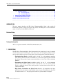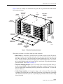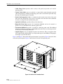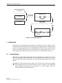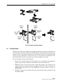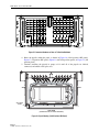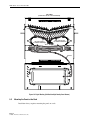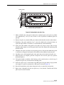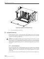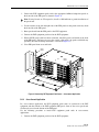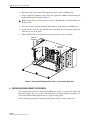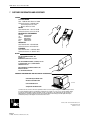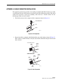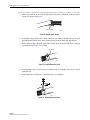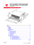
1
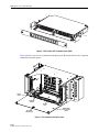
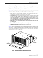
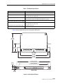
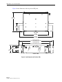
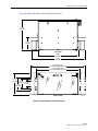
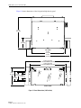
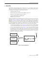
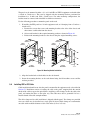
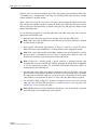
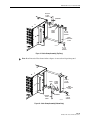
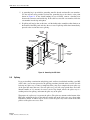
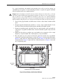
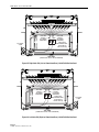
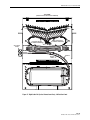
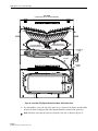
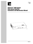
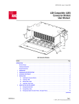
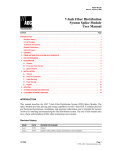
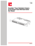
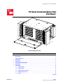
ADCP-90-328 • Issue 2 • November 2005
FPL Series Termination/Splice Panel
User Manual)
2
8
14
20
26
3
32
9
42
15
48
21
54
27
4
60
33
10
66
38
16
72
44
22
50
28
5
56
34
11
62
39
17
68
45
23
51
29
6
57
35
12
63
40
18
69
46
24
52
30
58
36
64
41
70
47
53
59
65
42
71
48
54
60
66
72
17807-A
FPL Termination/Splice Panel
Content
Page
INTRODUCTION . . . . . . . . . . . . . . . . . . . . . . . . . . . . . . . . . . . . . . . . . . . . . . . . . . . . . . . . . . . . . . . . . . . . . . . . . . . . . 2
Revision History . . . . . . . . . . . . . . . . . . . . . . . . . . . . . . . . . . . . . . . . . . . . . . . . . . . . . . . . . . . . . . . . . . . . . . . . 2
Trademark Information . . . . . . . . . . . . . . . . . . . . . . . . . . . . . . . . . . . . . . . . . . . . . . . . . . . . . . . . . . . . . . . . . . . 2
1
DESCRIPTION . . . . . . . . . . . . . . . . . . . . . . . . . . . . . . . . . . . . . . . . . . . . . . . . . . . . . . . . . . . . . . . . . . . . . . . . . . 2
2
ACCESSORIES . . . . . . . . . . . . . . . . . . . . . . . . . . . . . . . . . . . . . . . . . . . . . . . . . . . . . . . . . . . . . . . . . . . . . . . . . 8
3
SPECIFICATIONS AND DIMENSIONS . . . . . . . . . . . . . . . . . . . . . . . . . . . . . . . . . . . . . . . . . . . . . . . . . . . . . . . . . . 8
4
APPLICATION . . . . . . . . . . . . . . . . . . . . . . . . . . . . . . . . . . . . . . . . . . . . . . . . . . . . . . . . . . . . . . . . . . . . . . . . . 13
5
INSTALLATION . . . . . . . . . . . . . . . . . . . . . . . . . . . . . . . . . . . . . . . . . . . . . . . . . . . . . . . . . . . . . . . . . . . . . . . . 14
5.1
Installing Adapters . . . . . . . . . . . . . . . . . . . . . . . . . . . . . . . . . . . . . . . . . . . . . . . . . . . . . . . . . . . . . . . 14
5.2
Installing Pigtails . . . . . . . . . . . . . . . . . . . . . . . . . . . . . . . . . . . . . . . . . . . . . . . . . . . . . . . . . . . . . . . . 15
5.3
Mounting the Panel on the Rack . . . . . . . . . . . . . . . . . . . . . . . . . . . . . . . . . . . . . . . . . . . . . . . . . . . . . . 18
5.4
Installing OSP or IFC Cable. . . . . . . . . . . . . . . . . . . . . . . . . . . . . . . . . . . . . . . . . . . . . . . . . . . . . . . . . . 19
5.5
Splicing . . . . . . . . . . . . . . . . . . . . . . . . . . . . . . . . . . . . . . . . . . . . . . . . . . . . . . . . . . . . . . . . . . . . . . . 22
(continued)
1345101 Rev A
Page 1
© 2005, ADC Telecommunications, Inc.
ADCP-90-328 • Issue 2 • November 2005
Content (continued)
5.6
Page
Installing FOT Patch Cords . . . . . . . . . . . . . . . . . . . . . . . . . . . . . . . . . . . . . . . . . . . . . . . . . . . . . . . . . . 28
5.6.1
Interconnect Application . . . . . . . . . . . . . . . . . . . . . . . . . . . . . . . . . . . . . . . . . . . . . . . . . . . . 28
5.6.2
Cross-Connect Application . . . . . . . . . . . . . . . . . . . . . . . . . . . . . . . . . . . . . . . . . . . . . . . . . . . 29
6
OPERATION (CROSS-CONNECT PATCH CORDS) . . . . . . . . . . . . . . . . . . . . . . . . . . . . . . . . . . . . . . . . . . . . . . . . . 30
7
CUSTOMER INFORMATION AND ASSISTANCE . . . . . . . . . . . . . . . . . . . . . . . . . . . . . . . . . . . . . . . . . . . . . . . . . . . 32
APPENDIX A: SHIELD CONNECTOR INSTALLATION . . . . . . . . . . . . . . . . . . . . . . . . . . . . . . . . . . . . . . . . . . . . . . . . . . . . 33
_________________________________________________________________________________________________________
INTRODUCTION
This user manual describes the FPL Series Termination/Splice Panel, and provides all
information required to install and operate this product. All FPL panels can be mounted on
either a 19-inch or 23-inch WECO or EIA rack.
Revision History
quad cables and patch cord routing
ISSUE
DATE
REASON FOR CHANGE
Issue 1
07/2002
Original.
Issue 2
11/2005
Added 1RU 12/24 position panels.
Trademark Information
ADC is a registered trademark of ADC Telecommunications, Inc.
1
DESCRIPTION
The FPL Series Termination/Splice Panel documented in this manual may be any of a number
of rack-mounted panels built using the same chassis style and incorporating similar features
such as angled adapters and vertical cable guides. Panel configurations include the following:
• Termination Only Panels—Available with 12, 24, 48, 72, or 96 termination positions.
LX.5 and LC connectors may be used with the 12, 24, 48, and 72 position panels to double
the density. These panels require connectorized fibers on both sides of the termination
bulkhead.
• Termination and Splice Panels—Available with 12, 24, 48, 72, or 96 termination
positions. LX.5 and LC connectors may be used with the 12, 24, 48, and 72 position
panels to double the density. These panels provide a transition between bare fibers and
connectorized fibers.
• High Density Termination and Splice Panel—Provides 144 termination and splice
positions in the same chassis, using standard connector types. The bulkhead on this panel
is slanted inward in a “V” design to provide room for a greater number of adapters.
Page 2
© 2005, ADC Telecommunications, Inc.
ADCP-90-328 • Issue 2 • November 2005
Figure 1 shows an example of a termination only panel, the 72 position model. Other models
have analogous features.
ANGLED
ADAPTERS
ADJUSTABLE
MOUNTING
BRACKET
FPL
CHASSIS
ADJUSTABLE
MOUNTING
BRACKET
CABLE CLAMP
ASSEMBLY
VERTICAL
CABLE GUIDE
2
8
14
20
26
3
32
9
42
15
48
21
54
27
4
60
33
10
66
38
16
72
44
22
50
28
5
56
34
11
62
39
17
68
45
23
51
29
6
57
35
12
63
40
18
69
46
24
52
30
58
36
64
41
70
47
53
59
TERMINATION
BULKHEAD
65
42
71
48
54
60
66
72
CABLE
CLAMP
COVER
REMOVABLE
FRONT DOOR
VERTICAL
CABLE GUIDE
OPTIONAL
LOCK MOUNT
17816-A
PATCH CORD
DESIGNATION
CARD
Figure 1. 72 Position Termination Only Panel
The features called out are as follows (from top center clockwise):
• FPL Chassis—is the boxlike, solid metal frame on which the panel is built. The chassis
shown is 8.7 inches (22.1 cm) high, 16.4 inches (41.7 cm) wide, and 12.0 inches (30.5 cm)
deep. This same chassis is also used for the 48 and 96 position panels, as well as for the
48, 72, and 96 position termination and splice panels. Shorter-height chassis are used for
the 12 and 24 position panels and a deeper chassis is used for the 144 position high density
panel. For details, refer to Table 1 on Page 8.
• Adjustable Mounting Bracket—(one on each side) can be oriented to provide either 19inch or 23-inch WECO or EIA rack mounting with either a 4-inch or 5-inch recess. The
panel is shipped with the mounting brackets positioned for installation in a 19-inch rack
with a 5-inch recess.
• Cable Clamp Assembly—is a kit used to clamp a cable to the panel. Two cable clamp
assemblies are provided with every FPL panel. Each clamp can accommodate a maximum
cable diameter of 0.80 inch (2.03 cm). A grounding lug is included with each cable clamp
for use if needed.
Page 3
© 2005, ADC Telecommunications, Inc.
ADCP-90-328 • Issue 2 • November 2005
• Cable Clamp Cover—protects cable at entry to the panel (not present on 12 and 24
position panels).
• Vertical Cable Guide—(one on each side) is a metal cable retainer designed to provide
cable management by confining and directing patch cords to and from the panel and along
the frame on which the panel is installed.
• Patch Cord Designation Card—is a laminated card fastened to the inside of the panel
front door. The designation card is used to record the near-end and far-end termination
locations of each patch cord installed on the panel.
• Optional Lock Mount—provides ability to lock front door.
• Removable Front Door—protects the termination bulkhead and can be removed to
provide access to the bulkhead for connecting patch cords.
• Termination Bulkhead—provides a location for connecting patch cords. The bulkhead
shown has 72 holes for 72 adapters. Other bulkheads for the chassis size shown provide 48
or 96 locations for mounting connectors.
• Angled Adapters—are pass-through receptacles for connectors. They are angled to either
left or right to hold terminated fibers at an angle with respect to the bulkhead. The purpose
of the angle is prevent fiber bend.
Figure 2 and Figure 3 show the 48 and 96 position panels, respectively. Figure 4 shows the three
rack unit 24 position panel. Figure 5 shows the one rack unit 12/24 position panel.
01
07
13
19
02
08
14
25
20
31
03
37
09
43
15
26
21
32
04
38
10
44
16
27
22
33
05
39
11
45
17
28
23
34
06
40
12
46
18
29
24
35
41
47
30
36
42
48
17808-A
Figure 2. 48 Position FPL Termination Panel
Page 4
© 2005, ADC Telecommunications, Inc.
ADCP-90-328 • Issue 2 • November 2005
1
7
13
19
25
31
2
37
8
43
14
20
26
32
3
38
9
49
44
15
55
61
21
67
27
73
33
4
39
10
79
50
45
16
85
56
91
62
22
68
28
74
34
5
40
11
51
46
17
80
86
57
92
63
23
69
29
75
35
6
41
12
81
52
47
18
87
58
93
64
24
70
30
76
36
42
82
53
48
88
59
94
65
71
77
83
54
89
60
95
66
72
78
84
90
96
17815-A
Figure 3. 96 Position FPL Termination Panel
06
12
18
24
02
05
08
30
11
36
03
42
06
48
09
14
12
17
20
23
15
18
21
24
17820-A
Figure 4. 24 Position FPL Termination Panel (3RU)
Page 5
© 2005, ADC Telecommunications, Inc.
ADCP-90-328 • Issue 2 • November 2005
20973-A
Figure 5. 12/24 Position FPL Termination Panel (1RU)
Figure 6 shows a rear view of a termination and splice panel. The panel shown is the 72 position
termination and splice panel.
SPLICE
AREA
INTERNAL
PIGTAIL
17819-A
SPLICE
TRAY
OPTIONAL
LOCK MOUNT
REMOVABLE
REAR ACCESS
DOOR
Figure 6. FPL Termination and Splice Panel
Page 6
© 2005, ADC Telecommunications, Inc.
ADCP-90-328 • Issue 2 • November 2005
The front side of the 72 position termination and splice panel is identical to the termination only
panel shown in Figure 1. In general, the termination components of any FPL termination and
splice panel are identical to the termination components of the panel’s termination and splice
panel counterpart. Only the splice components are different.
Figure 6 on the preceding page shows the typical components unique to the splice function of a
termination and splice panel. They are as follows (from left to right in the figure):
• Splice Area—is a protected chamber within the chassis intended for splice trays. In
termination only panels, this area can be used for cable storage.
• Internal Pigtail—is a factory-installed fiber optic cable with a connector at one end and a
bare fiber on the other end. The connector end of the pigtail is terminated on the rear side
of the termination bulkhead. The bare end of the pigtail is available for splicing to a bare
fiber at the customer site. The cable from which the bare fibers are broken out for splicing
may be either Outside Plant (OSP) or Intra Facility Cable (IFC).
• Splice Tray—is a tray installed in the splice area. Each tray holds one or more splice chips
of a selected type.
• Removable Rear Access Door—provides access to the splice area.
• Optional Lock Mount—provides ability to lock rear access door.
Figure 7 shows the 144 position high density termination and splice panel. Additional features
called out here are the split termination bulkhead, which provides the room required for the
greater number of adapters, and the splice area access door, which opens into a locked
horizontal position to serve as a splice deck.
SPLICE AREA
ACCESS DOOR
SPLIT
TERMINATION
BULKHEAD
17906-A
Figure 7. 144 Position High Density Termination and Splice Panel
Page 7
© 2005, ADC Telecommunications, Inc.
ADCP-90-328 • Issue 2 • November 2005
2
ACCESSORIES
The following accessory items may be ordered separately for FPL panels:
• Single and dual splice trays (for types, see Splice Type in Table 1 below)
• Additional kits for clamping and grounding cables
• Key locks for front and rear doors
• Buildout attenuators (ST and biconic)
• Bulkhead attenuators (ST, SC, D4, FC, and biconic)
3
SPECIFICATIONS AND DIMENSIONS
Table 1 lists specifications for the FPL modules.
Table 1. FPL Modules Specifications
PARAMETER
SPECIFICATION
Common to All Panels
Rack mounting
19-inch (48.26 cm) or 23-inch (58.42 cm)
Hole spacing
EIA or WECO
Recess options
4-inch (10.16 cm) or 5-inch (12.7 cm) recess
Connector types
Multimode SC, SC duplex, ST©, LX.5©, and LC;
Singlemode FC, FC (zirconia adapter), FC (8o polish), SC, SC (zirconia adapter), SC (8o polish), SC duplex, ST©, ST© (zirconia adapter),
E-2000 (8o polish), E-2000 (flat polish), LX.5©, LC
Pigtail type
Stranded or ribbon
Splice type
Bare fusion, heat shrink fusion, mechanical, rotary, FibrLok, Raychem
Universal (R), Nortel, AFL
Pre-termination (optional) cable types
Multimode IFC stranded 62.5/125;
Singlemode IFC stranded, IFC plenum stranded, OSP single armor
stranded, indoor-outdoor, OSP dielectric stranded, IFC Maxi-Strip,
IFC ribbon, OSP single armor ribbon, OSP dielectric ribbon
12/24 Position Panel (1RU)
Dimensions (H x W x D)
1.72 inch x 17.0 in. x 11.48 in.
(4.4 cm x 43.2 cm x 29.2 cm)
Capacity
12 or 24 termination positions
LX.5© and LC connectors double the termination capacity
24 Position Panel (3RU)
Dimensions (H x W x D)
5.0 inch x 16.4 in. x 12.0 in.
(12.7 cm x 41.7 cm x 30.5 cm)
Capacity
24 termination positions
LX.5© and LC connectors double the termination capacity
Page 8
© 2005, ADC Telecommunications, Inc.
ADCP-90-328 • Issue 2 • November 2005
Table 1. FPL Modules Specifications
PARAMETER
SPECIFICATION
48/72/96 Position Panel (5RU)
Dimensions (H x W x D)
8.7.0 inch x 21.9 in. x 12.0 in.
(22.1 cm x 56.7 cm x 30.5 cm)
Capacity
48, 72, or 96 termination positions
LX.5© and LC connectors double the termination capacity
144 Position High Density Panel (5RU)
Dimensions (H x W x D)
Depth with rear door splice deck open
8.7.0 inch x 21.9 in. x 15.0 in.
(22.1 cm x 56.7 cm x 38.1 cm)
23.0 inch (58.42 cm)
Capacity
144 termination positions
Figure 8 shows dimensions for the 12/24 position 1RU panel.
11.48 IN.
(29.2 CM)
4.86 IN.
(12.3 CM)
TOP VIEW
17.0 IN.
(43.2 CM)
20.24 IN.
(51.4 CM)
22.32 IN. (56.7 CM)
23-IN. RACK MOUNT (58.4 CM)
1.72 IN.
(4.4 CM)
1.25 IN.
(3.2 CM)
18.32 IN. (46.5 CM)
19-IN. RACK MOUNT (48.3 CM)
FRONT VIEW
20959-A
Figure 8. 12/24 Position 1RU Panel
Page 9
© 2005, ADC Telecommunications, Inc.
ADCP-90-328 • Issue 2 • November 2005
Figure 9 shows dimensions of the 24 position 3RU panel.
12.0 IN.
(30.5 CM)
5.0 IN.
(12.7 CM)
TOP VIEW
16.4 IN.
(41.7 CM)
21.9 IN.
(55.5 CM)
22.32 IN. (56.7 CM)
23-IN. RACK MOUNT (58.4 CM)
18.32 IN. (46.5 CM)
19-IN. RACK MOUNT (48.3 CM)
4.0 IN.
(10.2 CM) 2.25 IN.
(5.7 CM)
5.0 IN.
(12.7 CM)
FRONT VIEW
Figure 9. Panel Dimensions (24 Position 3RU)
Page 10
© 2005, ADC Telecommunications, Inc.
17822-A
ADCP-90-328 • Issue 2 • November 2005
Figure 10 shows dimensions of the 48/72/96 position panel.
12.0 IN.
(30.5 CM)
5.0 IN.
(12.7 CM)
TOP VIEW
16.4 IN.
(41.7 CM)
21.9 IN.
(55.5 CM)
22.32 IN. (56.7 CM)
23-IN. RACK MOUNT (58.4 CM)
18.32 IN. (46.5 CM)
19-IN. RACK MOUNT (48.3 CM)
8.7 IN.
(22.1 CM)
4.0 IN.
(10.2 CM) 2.25 IN.
(5.7 CM)
5.0 IN.
(12.7 CM)
FRONT VIEW
17821-A
Figure 10. Panel Dimensions (48/72/96 Position)
Page 11
© 2005, ADC Telecommunications, Inc.
ADCP-90-328 • Issue 2 • November 2005
Figure 11 shows dimensions of the 144 position high density panel
15.0 IN.
(38.1 CM)
5.0 IN.
(12.7 CM)
TOP VIEW
16.4 IN.
(41.7 CM)
21.9 IN.
(55.5 CM)
22.32 IN. (56.7 CM)
23-IN. RACK MOUNT (58.4 CM)
18.32 IN. (46.5 CM)
19-IN. RACK MOUNT (48.3 CM)
8.7 IN.
(22.1 CM)
4.0 IN.
(10.2 CM) 2.25 IN.
(5.7 CM)
5.0 IN.
(12.7 CM)
FRONT VIEW
Figure 11. Panel Dimensions (144 Position)
Page 12
© 2005, ADC Telecommunications, Inc.
17824-A
ADCP-90-328 • Issue 2 • November 2005
4
APPLICATION
The FPL Series Termination/Splice Panel is designed for use in central offices, remote offices,
and in local area networks (LANs) that use a fiber optic cable system. The panel provides a
common point for performing any of the following functions:
• Terminating OSP or IFC cables
• Terminating Fiber Optic Terminal (FOT) equipment patch cords
• Storing excess FOT equipment patch cord length
• Connecting FOT equipment with OSP cables
• Mounting and protecting splices
When used with OSP cable, the FPL panel may be used for either interconnect or cross-connect
applications. Figure 12 and Figure 13 provide a pictorial comparison of these two types of
applications. As shown, in both interconnect and cross-connect applications, the OSP cable is
terminated on the rear side of the panel and spliced to the internal pigtails within the panel.
Also, in both applications, the pigtails are connected to the rear side of the adapters on the
termination bulkhead. The applications differ in what occurs on the front side of the panel.
• In an interconnect application, shown in Figure 12, patch cords from the FOT equipment
are connected directly to fibers spliced and terminated on the rear side of the same panel.
• In a cross-connect application, shown in Figure 13, patch cords from the FOT equipment
are terminated on one panel and the fibers are spliced and terminated on a second panel,
with cross-connect patch cords providing links between the two panels. This two-panel
arrangement provides more flexibility in testing and patching optical circuits than is
provided by a single panel arrangement.
OSP
CABLE
FOT EQUIPMENT
OSP CONNECTOR PANEL
FOT EQUIPMENT
FOT EQUIPMENT
PATCH CORDS
BULKHEAD
ADAPTER
PIGTAIL
SPLICE
FOT EQUIPMENT
2762-B
Figure 12. Interconnect Application
Page 13
© 2005, ADC Telecommunications, Inc.
ADCP-90-328 • Issue 2 • November 2005
FOT EQUIPMENT
FOT EQUIPMENT
CONNECTOR PANEL
FOT EQUIPMENT
FOT EQUIPMENT
PATCH CORDS
BULKHEAD
ADAPTER
FOT EQUIPMENT
CROSS-CONNECT
PATCH CORDS
OSP
CABLE
OSP CONNECTOR PANEL
BULKHEAD
ADAPTER
PIGTAIL
SPLICE
2763-B
Figure 13. Cross-Connect Application
5
INSTALLATION
Installation will vary depending on how the panel was outfitted in the factory and how it will be
used. Installation may include any of the following tasks: installing adapters; installing internal
pigtails; mounting the panel on the rack; installing OSP or IFC cable (either connectorized or
bare fiber); installing FOT patch cords; and installing cross-connect patch cords (in a crossconnect application only). For step by step instructions, refer to the following subsections.
5.1
Installing Adapters
FPL panels are usually shipped with adapters already installed; however, in some case, you may
need to install adapters. The exact procedure to be used depends on the adapter type. Figure 14
shows an example. For specific instructions, refer to the installation drawing that came with the
adapters.
Note: To avoid getting dirt into the adapter, leave the dust covers in place on the adapters
when mounting them on the retainers. If dirt does enter the adapter, use the ADC Fiber
Connector/Adapter Cleaning Kit (sold separately) to clean the adapter. Follow the
cleaning instructions provided with the kit.
Page 14
© 2005, ADC Telecommunications, Inc.
ADCP-90-328 • Issue 2 • November 2005
COMPRESS
RELEASE
TABS
COMPRESS
RELEASE
TABS
ROTATE AND
SNAP INTO
SLOT
ROTATE AND
SNAP INTO
SLOT
COMPRESS
RELEASE
TABS
COMPRESS
RELEASE
TABS
1
17846-A
2
Figure 14. Example of Installing Adapters
5.2
Installing Pigtails
Pigtails may be installed in any FPL panel (including termination only panels) to utilize the rear
area of the panel for splicing. Pigtails are installed with the connectorized end connected to the
adapters on the rear side of the termination panel and with the bare fiber ends positioned within
a splice tray (for an illustration, see Figure 6 on Page 6). 3m pigtails are used with the excess
slack coiled within the chassis to provide a service loop for future use if needed.
Use the following procedure to install pigtails:
1. Separate out 12 pigtails. Apply a pair of designation tags to each pigtail for identification.
Attach one tag next to the connector and the other tag near the bare fiber end.
2. Working from the rear side of the panel, connect the pigtails to the interior side of
adapters/receptacles marked with the corresponding numbers. The connector numbers are
silk-screened on the interior side of the bulkhead, as shown in Figure 15 for the 72
position panel.
3. Group the 12 pigtails into a bundle and use the twist-lock fiber retainers provided to hold
the bundle together.
Page 15
© 2005, ADC Telecommunications, Inc.
ADCP-90-328 • Issue 2 • November 2005
17825-A
Figure 15. Connector Numbers on Rear of 72 Position Bulkhead
4. Route the pigtails within the panel as shown in Figure 16 (12/24 position 1RU panel),
Figure 17 (24 position 3RU panel), Figure 18 (48/72/96 position panel), or Figure 19 (144
position panel).
5. Continue installing the pigtails in groups of 12 until all of the pigtails are labeled,
connected, and routed to the splice area.
OSP CABLE
CLAMP
20961-A
TOP VIEW
(SHOWN WITH TOP OF CHASSIS REMOVED)
Figure 16. Pigtail Routing (12/24 Position 1RU Panel)
Page 16
© 2005, ADC Telecommunications, Inc.
ADCP-90-328 • Issue 2 • November 2005
LEFT SIDE
PIGTAILS
(AS VIEWED
FROM REAR)
RIGHT SIDE
PIGTAILS
(AS VIEWED
FROM REAR)
KURLYLOCKS
OR FANNING TREE
(ATTACHED TO
TOP OF CHASSIS)
OSP CABLE
CLAMP
17920-A
TOP VIEW
(SHOWN WITH TOP OF CHASSIS REMOVED)
Figure 17. Pigtail Routing (24 Position 3RU Panel)
LEFT SIDE
PIGTAILS
(AS VIEWED
FROM REAR)
RIGHT SIDE
PIGTAILS
(AS VIEWED
FROM REAR)
KURLYLOCKS
OR FANNING TREE
(ATTACHED TO
TOP OF CHASSIS)
TOP VIEW
OSP CABLE
CLAMP
17919-A
(SHOWN WITH TOP OF CHASSIS REMOVED)
Figure 18. Pigtail Routing (48/72/96 Position Panel)
Page 17
© 2005, ADC Telecommunications, Inc.
ADCP-90-328 • Issue 2 • November 2005
TOP VIEW
(SHOWN WITH TOP OF CHASSIS REMOVED)
LEFT SIDE PIGTAILS
(AS VIEWED FROM REAR)
RIGHT SIDE PIGTAILS
(AS VIEWED FROM REAR)
PIGTAILS
17910-A
Figure 19. Pigtail Routing (144 Position High Density Panel Shown)
5.3
Mounting the Panel on the Rack
Installation always requires mounting the panel on a rack.
Page 18
© 2005, ADC Telecommunications, Inc.
ADCP-90-328 • Issue 2 • November 2005
The panel can be mounted in either a 19- or 23-inch EIA or WECO equipment rack with either
a 4-inch or 5-inch recess. The panel is shipped with the mounting brackets positioned for
installation in a 19-inch rack with a 5-inch recess. For other mounting configurations, the
brackets must be removed and reinstalled in a different orientation.
Use the following procedure to mount the panel on the rack:
1. If installing the FPL panel in a 23-inch equipment rack, or if changing from a 5-inch to a
4-inch recess:
a. Remove the screws that secure each mounting bracket to the sides of the chassis and
then remove each bracket from the chassis.
b. Orient each bracket for the required mounting position as shown in Figure 20.
c. Refasten the mounting brackets to the chassis using the original mounting screws.
5-INCH
RECESS
4-INCH
RECESS
5-INCH
RECESS
4-INCH
RECESS
60
60
66
66
72
72
56
56
62
62
68
68
57
57
63
63
69
69
58
58
64
64
70
70
59
59
65
65
71
71
60
60
66
66
72
72
19-INCH
MOUNTING
23-INCH
MOUNTING
17827-A
Figure 20. Mounting Bracket Installation
2. Align the bracket holes with the holes in the rack channel.
3. Secure the mounting brackets to the rack channel using the #12 machine screws and flat
washers provided.
5.4
Installing OSP or IFC Cable
Cable installation should occur after the panel is mounted in the equipment rack, as described in
Section 5.3. Installation consists of routing the cable to the panel, stripping back the outside
sheath of the cable to expose the optical fibers, installing a cable clamp to secure the cable to the
panel, and routing the fibers to the splice tray. The cable must also be grounded if it has a
metallic sheath or metallic strength member.
The cable clamp used in cable installation is shipped with the panel. Two clamps are provided
since two cables may be installed on a single panel if desired. Each clamp can accommodate
one cable with an outside diameter of 0.4 to 0.8 inches (1.02 to 2.03 cm).
Page 19
© 2005, ADC Telecommunications, Inc.
ADCP-90-328 • Issue 2 • November 2005
Typically, only one cable is installed per panel. The cable clamp can be installed on either side.
A grounding lug is included with each clamp for grounding OSP cables that have metallic
strength members or metallic sheaths.
Allow a fiber service loop of at least 8 feet (2.5 meters) when stripping the sheath off the cable.
This will provide sufficient length for routing the buffer tubes within the FPL panel and for
splicing. After entry, the buffer tubes are routed to the splice tray. The splice tray mounts on the
bottom of the FPL panel.
Use the following procedure to secure the OSP cable at the fiber entry point and to route the
optical fibers into the FPL panel:
1. Route the OSP cable to the selected entry opening at the side of the FPL panel.
Note: Cables may enter the FPL panel from either the top or bottom and may be clamped
to either the left or right side
2. Strip back the cable sheath approximately 96 inches (2.5 meters) to expose the optical
fibers. Follow the cable manufacturer’s recommendations when stripping the sheath.
Note: If the cable is filled with water blocking compound, the cable end must be sealed to
prevent leakage. A blocking kit (accessory item) is required for sealing the cable end.
Install the kit according to the instructions provided with the kit.
Note: If cable has a metallic sheath, a special connector is provided with the cable
grounding kit (accessory item FIP-ACC-GK) for grounding the sheath. Refer to Appendix
A for the installation procedures for ScotchLok 4460 Shield Connectors which are
manufactured by the 3M Company.
3. Determine the correct clamp and grommet combination required to secure the cable to the
panel. A rubber clamp and three grommets of various sizes are provided. Select a grommet
that when placed around the cable, has a gap of nearly zero to 0.30 inches (0.76 cm). If the
cable diameter is greater than 0.70 inches (1.78 cm), only the rubber clamp is required.
4. Use the rubber clamp, clamp cover, grommet (if required), and two screws to secure the
cable end to the side of the FPL panel chassis, as shown in Figure 21 for a top entry cable
and in Figure 22 for a bottom entry cable.
Note: The Rear Protective Plate, identified in the figures, is not used with the 24 position
panel. The plate is not included in the cable clamp kit.
Page 20
© 2005, ADC Telecommunications, Inc.
ADCP-90-328 • Issue 2 • November 2005
OUTSIDE
PLANT
CABLE
GROMMET
60
YOKES
66
72
CABLE
CLAMP
COVER
56
62
68
57
63
#6 - 32 x
1.375-IN.
SCREWS
69
58
64
70
REAR
PROTECTIVE
PLATE
59
65
71
60
66
72
17828-A
#6 - 32 x
0.25-IN.
SCREWS
Figure 21. Cable Clamp Assembly (Top Entry)
Note: Rear Protective Plate shown in these figures is not used on 24 position panel.
60
66
72
56
62
68
57
63
YOKES
69
58
64
#6 - 32 x
0.25-IN.
SCREWS
CABLE
CLAMP
COVER
70
REAR
PROTECTIVE
PLATE
59
65
71
60
66
72
GROMMET
OUTSIDE
PLANT
CABLE
17829-A
#6 - 32 x
1.375-IN.
SCREWS
Figure 22. Cable Clamp Assembly (Bottom Entry)
Page 21
© 2005, ADC Telecommunications, Inc.
ADCP-90-328 • Issue 2 • November 2005
5. A grounding lug is provided for grounding metallic sheaths and metallic core members.
Use the nut and screw provided to fasten the grounding lug to the chassis at the point
shown in Figure 23. If the sheath bonding kit was installed, connect a bonding wire
between the connector stud and the lug. If the cable has a metallic core member, insert the
core member into the lug and tighten.
6. If splicing will not be done at this time, coil the buffer tubes around the radius limiters on
the bottom of the FPL panel and close the rear cover. If splicing will be done immediately,
proceed to the section that covers splicing.
OUTSIDE
PLANT
CABLE
SHEATH BONDING
KIT CONNECTOR
60
66
72
56
62
68
57
63
BONDING
WIRE
69
58
64
70
GROUNDING
LUG
REAR
PROTECTIVE
PLATE
59
65
71
60
66
72
17830-A
Figure 23. Grounding the OSP Cable
5.5
Splicing
If you are installing a termination and splicing panel, and have just finished installing your OSP
or IFC cable, you can now proceed to the splicing procedure provided in this section. You will
be doing one splice tray at a time to completion, then going on to complete the next splice tray
(if the panel has more than one). For each splice tray, you will assign paired fibers and cable
subunits bundles of 12, measure for correct service loop length, remove the splice tray to a
working surface for splicing, and return the splice tray to the panel.
The purpose of a splice tray is to protect the splices. The splice tray mounts on the bottom of the
FPL panel, within the chassis in the mid-size models and on the splice area access door in the
high density model. A rubber strap is used to secure the splice tray to the bottom of the FPL
panel or to the splice area access door.
Page 22
© 2005, ADC Telecommunications, Inc.
ADCP-90-328 • Issue 2 • November 2005
In a typical installation, the methods and procedures that will be used for splicing are
determined by local practice. Use the following procedure to organize the pigtails and buffer
tubes for splicing and to store completed splices:
Danger: Infrared radiation is invisible and can seriously damage the retina of the eye. Do not
look into the optical bulkhead of an operational transmitter or into the receiver end of an active
fiber. A protective cap or hood MUST be immediately placed over any radiating bulkhead
adapter/receptacle or optical fiber connector to avoid potential exposure to dangerous infrared
optical radiation. The protective cover also prevents dirt particles from entering the connector.
1. Uncoil all the pigtail bundles and buffer tubes from the radius limiters within the FPL
panel.
2. Group the pigtails and buffer tubes for fibers 1 - 12 into a single common bundle. Use the
twist-lock retainers provided to hold the pigtail and buffer tube bundle together.
3. Group the remaining pigtails and buffer tubes into similar bundles with one bundle for
each group of 12 pigtails and buffer tubes. Secure the bundles together using twist-lock
retainers.
4. Identify the first splice tray and the one or two bundles to be assigned to it. For a single
height tray, assign one bundle. For a dual height tray, assign two bundles.
5. Place the splice tray in its correct location in the panel and coil the one or two bundles
assigned to it around the radius limiters as shown in Figure 24 (12/24 position 1RU panel),
Figure 25 (right cable exit, 24/48/72/96 position panel), Figure 26 (left cable exit, 48/72/
96 position panel), Figure 27 (right cable exit, 144 position panel), or Figure 28 (left cable
exit, 144 position panel).
OSP CABLE
CLAMP
20961-A
TOP VIEW
(SHOWN WITH TOP OF CHASSIS REMOVED)
Figure 24. Pigtail Routing (12/24 Position 1RU Panel)
Page 23
© 2005, ADC Telecommunications, Inc.
ADCP-90-328 • Issue 2 • November 2005
LEFT SIDE
PIGTAILS
(AS VIEWED
FROM REAR)
RIGHT SIDE
PIGTAILS
(AS VIEWED
FROM REAR)
KURLYLOCKS
OR FANNING TREE
(ATTACHED TO
TOP OF CHASSIS)
OSP CABLE
CLAMP
17920-A
TOP VIEW
(SHOWN WITH TOP OF CHASSIS REMOVED)
Figure 25. Right Cable Exit (Left as Viewed from Rear), 24/48/72/96 Position Panel
LEFT SIDE
PIGTAILS
(AS VIEWED
FROM REAR)
RIGHT SIDE
PIGTAILS
(AS VIEWED
FROM REAR)
KURLYLOCKS
OR FANNING TREE
(ATTACHED TO
TOP OF CHASSIS)
TOP VIEW
OSP CABLE
CLAMP
17919-A
(SHOWN WITH TOP OF CHASSIS REMOVED)
Figure 26. Left Cable Exit (Right as Viewed from Rear), 24/48/72/96 Position Panel
Page 24
© 2005, ADC Telecommunications, Inc.
ADCP-90-328 • Issue 2 • November 2005
TOP VIEW
(SHOWN WITH TOP OF CHASSIS REMOVED)
LEFT SIDE PIGTAILS
(AS VIEWED FROM REAR)
RIGHT SIDE PIGTAILS
(AS VIEWED FROM REAR)
OSP CABLE
CLAMP
PIGTAILS
BUFFER
TUBES
17909-A
Figure 27. Right Cable Exit (Left as Viewed from Rear), 144 Position Panel
Page 25
© 2005, ADC Telecommunications, Inc.
ADCP-90-328 • Issue 2 • November 2005
TOP VIEW
(SHOWN WITH TOP OF CHASSIS REMOVED)
LEFT SIDE PIGTAILS
(AS VIEWED FROM REAR)
RIGHT SIDE PIGTAILS
(AS VIEWED FROM REAR)
OSP CABLE
CLAMP
PIGTAILS
BUFFER
TUBES
17918-A
Figure 28. Left Cable Exit (Right as Viewed from Rear),144 Position Panel
6. Lay the bundle(s) across the top of the splice tray as shown in the figures and determine
the point at which each pigtail and cable subunit should be attached to the splice tray.
Note: All fibers must enter the splice tray from the same side as shown in Figure 29.
Page 26
© 2005, ADC Telecommunications, Inc.
ADCP-90-328 • Issue 2 • November 2005
BUFFER TUBES
SECURE PIGTAILS AND BUFFER TUBES
TO SPLICE TRAY WITH TIE WRAPS
2776-A
Figure 29. Routing Bundles into Splice Tray
7. Mark each buffer tube and pigtail to indicate the attachment point to the splice tray. Make
sure approximately 2 feet (61 cm) of fiber are left beyond the attachment point for
splicing.
8. Remove the splice tray from the FPL panel and uncoil the bundles from the radius limiters.
9. Beginning at the points marked in step 7, remove the buffer tubes and pigtail jackets to
expose the optical fibers. Clean fibers as recommended by cable manufacturer.
10. Secure the cable subunits and pigtails to the splice tray using tie wraps. The tie wraps
should be tight enough to secure the pigtail jackets and cable subunits but should not pinch
the fibers inside.
11. Complete each splice according to local splicing practice. Note that the numbered tag that
is attached to each pigtail corresponds to the number on the bulkhead connector plate.
12. Carefully secure each completed splice to the splice chip on the inside of the splice tray.
13. When all splices are complete, place the clear plastic cover over the splice tray to protect
the finished splices.
14. Coil up the bundles around the radius limiters (in the same direction as coiled in step 5)
and place the splice tray on the bottom of the FPL panel.
15. Secure the splice tray(s) to the bottom of the FPL panel using the rubber strap provided.
An example of a splice tray mounted in a FPL panel is shown in Figure 30.
16. Record all terminations on the front designation cards as required by local practice.
17. Repeat steps 4 through 16 for the next splice tray, if any remains. Continue until all the
splice trays have been installed.
Page 27
© 2005, ADC Telecommunications, Inc.
ADCP-90-328 • Issue 2 • November 2005
17832-A
Figure 30. Splice Tray Mounted in 24 Position FPL Panel
18. Close and latch front and rear covers.
5.6
Installing FOT Patch Cords
In both interconnect and cross-connect applications, FOT equipment patch cords are installed
between the FOT equipment and the FLP panel. The following sections describe the installation
procedure to use based on the application.
Danger: Infrared radiation is invisible and can seriously damage the retina of the eye. Do not
look into the optical bulkhead of an operational transmitter or into the receiver end of an active
fiber. A protective cap or hood MUST be immediately placed over any radiating bulkhead
adapter/receptacle or optical fiber connector to avoid the potential exposure to dangerous
infrared optical radiation. The protective cover also prevents dirt particles from entering the
connector.
5.6.1
Interconnect Application
In an interconnect application, the FOT equipment patch cords are connected to the appropriate
bulkhead adapters/receptacles at the OSP-dedicated FPL panel and then routed to the FOT
equipment. Any excess patch cord slack must be stored at the FOT equipment or in a separate
storage panel.
Use the following procedure to install FOT equipment patch cords in interconnect applications:
Page 28
© 2005, ADC Telecommunications, Inc.
ADCP-90-328 • Issue 2 • November 2005
1. Connect the FOT equipment patch cord to the appropriate bulkhead adapter/receptacle at
the front side of the FPL panel as shown in Figure 31.
Note: If using biconic or ST receptacles, install a 0 dB build-out to permit installation of
the patch cord.
2. Use the retainers at the left and right sides of the FPL panel to route patch cords away from
the front side of the FPL panel.
3. Route patch cord from the FPL panel to the FOT equipment.
4. Connect the FOT equipment patch cord to the FOT equipment.
5. When all FOT patch cords have been connected, install the patch cord shields at the front
of the FPL panel. (For better access to the vertical cable guides, the patch cord shield may
optionally be removed during installation, as shown in Figure 31.)
6. Close FPL panel front cover and latch.
PATCH
CORDS
PATCH
CORDS
2
8
14
20
26
3
32
9
42
15
48
21
54
27
4
60
33
10
66
38
16
72
44
22
50
28
5
56
34
11
62
39
17
68
45
23
51
29
6
57
35
12
63
40
18
69
46
24
PATCH
CORD
SHIELD
52
30
58
36
64
41
70
47
53
59
65
42
71
48
54
60
66
72
PATCH
CORD
SHIELD
17836-A
Figure 31. Connecting FOT Equipment Patch Cords — Interconnect Application
5.6.2
Cross-Connect Application
In a cross-connect application, the FOT equipment patch cords are connected to the FOT
equipment and then routed to the FOT equipment FPL panel. Some of the excess patch cord
slack may be stored on the bottom of the FPL panel.
Use the following procedure to install FOT equipment patch cords in cross-connect
applications:
1. Connect the FOT equipment patch cord to the FOT equipment.
Page 29
© 2005, ADC Telecommunications, Inc.
ADCP-90-328 • Issue 2 • November 2005
2. Route the patch cord from the FOT equipment to the rear side of the FPL panel.
3. Connect the FOT equipment patch cord to the appropriate bulkhead adapter/receptacle
within the FPL panel as shown in Figure 32.
Note: If using biconic or ST receptacles, install a 0 dB build-out to permit installation of
the patch cord.
4. Coil excess patch cord slack around the radius limiters on the bottom of the FPL panel.
5. Use the retainers at the top, left, and right sides of the FPL panel to route patch cords away
from the rear side of the panel.
6. When all FOT patch cords have been connected, close the rear cover and latch.
FROM FOT
EQUIPMENT
FROM FOT
EQUIPMENT
17835-A
Figure 32. Connecting FOT Equipment Patch Cords — Cross-Connect Application
6
OPERATION (CROSS-CONNECT PATCH CORDS)
Cross-connect patch cords are routed between FPL panels by way of vertical cable guides and
horizontal troughs. Any excess patch cord length must be taken up within the guideways or
stored using Interbay Management Panels or a separate storage panel.
Use the following procedure for routing and connecting each cross-connect patch cord:
Page 30
© 2005, ADC Telecommunications, Inc.
ADCP-90-328 • Issue 2 • November 2005
1. Open the front cover of both the FOT equipment and OSP-dedicated FPL panel.
Danger: Infrared radiation is invisible and can seriously damage the retina of the eye. Do not
look into the optical bulkhead of an operational transmitter or into the receiver end of an active
fiber. A protective cap or hood MUST be immediately placed over any radiating bulkhead
adapter/receptacle or optical fiber connector to avoid the potential exposure to dangerous
infrared optical radiation. The protective cover also prevents dirt particles from entering the
connector.
2. Connect the cross-connect jumper to the appropriate bulkhead adapter/receptacle at the
front side of the first FPL panel as shown in Figure 33.
Note: If using biconic or ST receptacles, install a 0 dB build-out to permit installation of
the patch cord.
3. Use the retainers at the left and right sides of the FPL panel to route patch cords away from
the front side of the FPL panel.
4. Route patch cord from the first FPL panel to the second FPL panel.
5. Connect the cross-connect jumper to the appropriate bulkhead adapter/receptacle at the
front side of the second FPL panel as shown in Figure 33.
Note: For better access to the vertical cable guides, the patch cord shield may optionally
be removed during installation, as shown in Figure 33.
6. Close the front covers on both FPL panels and latch.
PATCH
CORDS
PATCH
CORDS
2
8
14
20
26
3
32
9
42
15
48
21
54
27
4
60
33
10
66
38
16
72
44
22
50
28
5
56
34
11
62
39
17
68
45
23
51
29
6
57
35
12
63
40
18
69
46
24
PATCH
CORD
SHIELD
52
30
58
36
64
41
70
47
53
59
65
42
71
48
54
60
66
72
PATCH
CORD
SHIELD
17836-A
Figure 33. Connecting Cross-Connect Patch Cords
Page 31
© 2005, ADC Telecommunications, Inc.
ADCP-90-328 • Issue 2 • November 2005
7
CUSTOMER INFORMATION AND ASSISTANCE
PHONE:
U.S.A. OR CANADA
Sales: 1-800-366-3891 Extension 73000
Technical Assistance: 1-800-366-3891
Connectivity Extension 73475
Wireless Extension 73476
EUROPE
Sales Administration: +32-2-712-65 00
Technical Assistance: +32-2-712-65 42
EUROPEAN TOLL FREE NUMBERS
Germany: 0180 2232923
UK:
0800 960236
Spain:
900 983291
France: 0800 914032
Italy:
0800 782374
ASIA/PACIFIC
Sales Administration: +65-6294-9948
Technical Assistance: +65-6393-0739
ELSEWHERE
Sales Administration: +1-952-938-8080
Technical Assistance: +1-952-917-3475
WRITE:
ADC TELECOMMUNICATIONS, INC
PO BOX 1101,
MINNEAPOLIS, MN 55440-1101, USA
ADC TELECOMMUNICATIONS (S'PORE) PTE. LTD.
100 BEACH ROAD, #18-01, SHAW TOWERS.
SINGAPORE 189702.
ADC EUROPEAN CUSTOMER SERVICE, INC
BELGICASTRAAT 2,
1930 ZAVENTEM, BELGIUM
PRODUCT INFORMATION AND TECHNICAL ASSISTANCE:
[email protected]
[email protected]
[email protected]
13944-RM
[email protected]
Contents herein are current as of the date of publication. ADC reserves the right to change the contents without prior notice.
In no event shall ADC be liable for any damages resulting from loss of data, loss of use, or loss of profits and ADC further
disclaims any and all liability for indirect, incidental, special, consequential or other similar damages. This disclaimer of
liability applies to all products, publications and services during and after the warranty period. This publication may be
verified at any time by contacting ADC's Technical Assistance Center.
© 2005, ADC Telecommunications, Inc.
All Rights Reserved
Printed in U.S.A
Page 32
© 2005, ADC Telecommunications, Inc.
ADCP-90-328 • Issue 2 • November 2005
APPENDIX A: SHIELD CONNECTOR INSTALLATION
This appendix provides the procedures for installing Scotchlok 4460 Shield Connectors, which
are manufactured by the 3M Company and utilized in the Fiber Management Panel. The shield
connector kit provides a means for grounding cables that have a metallic shield. Use the
following procedure to install each kit:
1. The shield connector kit is comprised of the components shown in Figure 34.
2 SECURING NUTS
TOP
BASE
9172-A
Figure 34. Kit Components
2. Prepare the cable by cutting the shield flush with the outer cable sheath as shown in Figure 35.
If the cable has a double sheath, cut only the outer sheath and shield leaving the inner sheath
intact as shown.
SINGLE SHEATH CABLE
CABLE
SHEATH
CORE
WRAP
.75 IN. (19 mm)
DOUBLE SHEATH CABLE
0.13 IN
(3mm)
OUTER
SHEATH
INNER
SHEATH
.75 IN. (19 mm)
CORE
WRAP
9173-A
Figure 35. Cable Preparation
Page 33
© 2005, ADC Telecommunications, Inc.
ADCP-90-328 • Issue 2 • November 2005
Reproduced by permission of 3M Company, from 3M Instruction Bulletin, Issue 1, dated February 1985, Number 43-7018-2209-9.
3. Make a one-inch cut in the cable sheath opposite the point at which the connector will be
attached as shown in Figure 36.
1.0 IN. (25 mm)
9174-A
Figure 36. Cutting Cable Sheath
4. If installing single shield cable, insert connector base between shield and core wrap. If
installing double shield cable, insert connector base between shield and inner sheath.
5. Slide connector into cable until stops contact outer sheath. Tap on shield above connector
at point shown in Figure 37 to set teeth.
TAP HERE
9175-A
Figure 37. Setting Connector Teeth
6. Install bonding wire on stud and place connector top over bonding wire. Do not tap on
connector top.
7. Install both nuts on connector as shown in Figure 38 and tighten.
9176-A
Figure 38. Bonding Wire Installation
Page 34
© 2005, ADC Telecommunications, Inc.