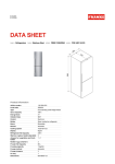
1
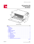
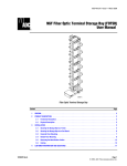
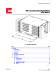
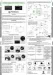
ADCP-90-279 • Issue 3 • May 2005
Next Generation Frame (NGF)
Fiber Combination Block (FCB)
User Manual)
Fiber Combination Block
Content
Page
INTRODUCTION . . . . . . . . . . . . . . . . . . . . . . . . . . . . . . . . . . . . . . . . . . . . . . . . . . . . . . . . . . . . . . . . . . . . . . . . . . . . . 2
Revision History . . . . . . . . . . . . . . . . . . . . . . . . . . . . . . . . . . . . . . . . . . . . . . . . . . . . . . . . . . . . . . . . . . . . . . . . 2
Trademark Information . . . . . . . . . . . . . . . . . . . . . . . . . . . . . . . . . . . . . . . . . . . . . . . . . . . . . . . . . . . . . . . . . . . 2
Related Publications . . . . . . . . . . . . . . . . . . . . . . . . . . . . . . . . . . . . . . . . . . . . . . . . . . . . . . . . . . . . . . . . . . . . . 2
1
PRODUCT DESCRIPTION . . . . . . . . . . . . . . . . . . . . . . . . . . . . . . . . . . . . . . . . . . . . . . . . . . . . . . . . . . . . . . . . . . 3
1.1
General Description. . . . . . . . . . . . . . . . . . . . . . . . . . . . . . . . . . . . . . . . . . . . . . . . . . . . . . . . . . . . . . . . 3
1.2
Main Components and Features . . . . . . . . . . . . . . . . . . . . . . . . . . . . . . . . . . . . . . . . . . . . . . . . . . . . . . . 4
1.3
Round Splice Tray . . . . . . . . . . . . . . . . . . . . . . . . . . . . . . . . . . . . . . . . . . . . . . . . . . . . . . . . . . . . . . . . . 6
2
SPECIFICATIONS. . . . . . . . . . . . . . . . . . . . . . . . . . . . . . . . . . . . . . . . . . . . . . . . . . . . . . . . . . . . . . . . . . . . . . . . 7
3
UNPACKING THE PRODUCT . . . . . . . . . . . . . . . . . . . . . . . . . . . . . . . . . . . . . . . . . . . . . . . . . . . . . . . . . . . . . . . . 7
4
INSTALLATION OVERVIEW . . . . . . . . . . . . . . . . . . . . . . . . . . . . . . . . . . . . . . . . . . . . . . . . . . . . . . . . . . . . . . . . . 7
5
INSTALLING PIGTAILS . . . . . . . . . . . . . . . . . . . . . . . . . . . . . . . . . . . . . . . . . . . . . . . . . . . . . . . . . . . . . . . . . . . . 8
6
MOUNTING THE FCB ON THE RACK . . . . . . . . . . . . . . . . . . . . . . . . . . . . . . . . . . . . . . . . . . . . . . . . . . . . . . . . . . 10
7
INSTALLING CABLES . . . . . . . . . . . . . . . . . . . . . . . . . . . . . . . . . . . . . . . . . . . . . . . . . . . . . . . . . . . . . . . . . . . . 11
(continued)
1325817 Rev A
Page 1
© 2005, ADC Telecommunications, Inc.
ADCP-90-279 • Issue 3 • May 2005
Content (continued)
8
Page
7.1
Breaking Out the Cable . . . . . . . . . . . . . . . . . . . . . . . . . . . . . . . . . . . . . . . . . . . . . . . . . . . . . . . . . . . . 11
7.2
Installing a Blocking Kit . . . . . . . . . . . . . . . . . . . . . . . . . . . . . . . . . . . . . . . . . . . . . . . . . . . . . . . . . . . . 12
7.3
Installing a Cable Clamp . . . . . . . . . . . . . . . . . . . . . . . . . . . . . . . . . . . . . . . . . . . . . . . . . . . . . . . . . . . 12
LOADING THE ROUND SPLICE TRAY . . . . . . . . . . . . . . . . . . . . . . . . . . . . . . . . . . . . . . . . . . . . . . . . . . . . . . . . . 16
8.1
Standard Splice Configuration . . . . . . . . . . . . . . . . . . . . . . . . . . . . . . . . . . . . . . . . . . . . . . . . . . . . . . . 16
8.1.1
8.2
Breaking Out Cable Subunits and Pigtails . . . . . . . . . . . . . . . . . . . . . . . . . . . . . . . . . . . . . . . . . 16
8.1.2
Left-Oriented FCBs (Clockwise Wind). . . . . . . . . . . . . . . . . . . . . . . . . . . . . . . . . . . . . . . . . . . . 18
8.1.3
Right-Oriented FCBs (Counter-Clockwise Wind). . . . . . . . . . . . . . . . . . . . . . . . . . . . . . . . . . . . . 22
24-Fiber Heat-Shrink Configuration (144 FCB With LX.5 Only) . . . . . . . . . . . . . . . . . . . . . . . . . . . . . . . . . . 26
8.2.1
Breaking Out Cable Subunits and Pigtails . . . . . . . . . . . . . . . . . . . . . . . . . . . . . . . . . . . . . . . . . 26
8.2.2
Left-Oriented FCBs (Clockwise Wind). . . . . . . . . . . . . . . . . . . . . . . . . . . . . . . . . . . . . . . . . . . . 28
8.2.3
Right-Oriented FCBs (Counter-Clockwise Wind). . . . . . . . . . . . . . . . . . . . . . . . . . . . . . . . . . . . . 32
9
SPLICING. . . . . . . . . . . . . . . . . . . . . . . . . . . . . . . . . . . . . . . . . . . . . . . . . . . . . . . . . . . . . . . . . . . . . . . . . . . . 36
10
INSTALLING PATCH CORDS . . . . . . . . . . . . . . . . . . . . . . . . . . . . . . . . . . . . . . . . . . . . . . . . . . . . . . . . . . . . . . . 36
11
CUSTOMER INFORMATION AND ASSISTANCE . . . . . . . . . . . . . . . . . . . . . . . . . . . . . . . . . . . . . . . . . . . . . . . . . . . 38
_________________________________________________________________________________________________________
INTRODUCTION
This manual describes the Next Generation Frame (NGF) Fiber Combination Block (FCB), and
provides instructions for installing this product. The FCB may be installed either on an NGF
Slim Rack or on a Fiber Main Distribution Frame (FMDF). It may have been ordered empty or
loaded with pre-terminated pigtails. This guide addresses all installation options, either by
providing instructions or by referring to related publications sent with kits.
Revision History
ISSUE
DATE
Issue 1
06/2001
REASON FOR CHANGE
Original.
Issue 2
07/2001
Technical update to provide more thorough instructions.
Issue 3
05/2005
Figure 6 corrected to show correct breakout point. Cover photo changed. Customer info updated.
Trademark Information
ADC is a registered trademark of ADC Telecommunications, Inc.
Related Publications
Title
Next Generation Frame (NGF) Slim Rack Installation Manual
Fiber Main Distribution Frame (FMDF) Installation Manual
FMDF Patch Cord Cross-Connect and Interconnect Procedures
Page 2
© 2005, ADC Telecommunications, Inc.
ADCP Number
90-272
93-273
90-240
ADCP-90-279 • Issue 3 • May 2005
1
1.1
PRODUCT DESCRIPTION
General Description
The Fiber Combination Block (FCB) is a Next Generation Frame (NGF) equipment panel that
provides a combination of splicing and termination functions. The FCB may be mounted on
either a Fiber Main Distribution Frame (FMDF) or NGF Slim Rack. FCBs are available with
different adapter types in block configurations of 48, 72, 96, or 144 (LX.5 only) positions. FCBs
also have a left or right orientation for mounting on the left or right side of the rack.
Figure 1 provides a functional overview of the FCB. Outside Plant (OSP) or Intrafacility (IFC)
cables are brought in from above or below the FCB (called upward and downward exit,
respectively). The cables are spliced to pigtails in the round splice trays in the bottom area of
the FCB. The pigtails transition to the Fiber Termination Block (FTB), where they are
terminated to adapter/connectors. Patch cords, routed through the NGF rack “Z” trough, are
used to complete optic circuits or for patching and testing.
FIBER
TERMINATION
BLOCK
PIGTAILS
PATCH
CORD
NGF RACK
"Z" TROUGH
16692-A
OSP OR IFC
CABLE
ROUND
SPLICE TRAY
Figure 1. Functional Overview of an FCB (Cable Downward Exit Shown)
Page 3
© 2005, ADC Telecommunications, Inc.
ADCP-90-279 • Issue 3 • May 2005
1.2
Main Components and Features
Figure 2 shows the main components and features of a Fiber Combination Block (in this case,
the 72-position, left-oriented model). The FCB consists of an upper component called the Fiber
Termination Block (FTB) and a lower component called the splice chassis. The FTB by itself is
identical to FTBs sold (without splice chassis) as stand-alone units.
16691-ARM
Figure 2. FCB Features (72-Position Left-Oriented Model)
The splice chassis door provides entrance to the splice chassis. Round splice trays within the
splice chassis hold splice chips and service coils for splices. Splice trays in the left-oriented
version are numbered from left to right (when viewed from the front), with the number 1 tray
adjacent to the splice chassis door, as shown.
Page 4
© 2005, ADC Telecommunications, Inc.
ADCP-90-279 • Issue 3 • May 2005
The FCB is also available in a right-oriented model. Splice trays in the right-oriented model are
also numbered from left to right. This places the splice trays in a reverse sequence with respect
to the module features, with the number 6 splice tray adjacent to the splice chassis door, as
shown in Figure 3.
16690-A
SPLICE
TRAY 1
SPLICE
TRAY 6
Figure 3. Right-Oriented CFB (72-Position Model Shown)
Radius-limiting spools guide pigtails from splice trays to their point of termination in the FTB.
Strain reliefs and cable tie-down locations are used to secure the OSP or IFC cable being routed
to the round splice trays. The FCB is shipped with a cable clamp kit that is installed on the rack
adjacent to the FCB. The kit includes ground fittings for OSP cable.
The upper component, the FTB, has a front and side cover. The side cover provides access to
the area where pigtails are routed into the termination block. The FTB uses sliding adapter
packs to provide termination locations for patch cords.
Page 5
© 2005, ADC Telecommunications, Inc.
ADCP-90-279 • Issue 3 • May 2005
Front edge protectors in the FTB are used to guide patch cords to the NGF rack “Z” trough,
through which they are routed to other FTBs or to fiber optic equipment. Either an interconnect
or cross-connect configuration may be used.
1.3
Round Splice Tray
The round splice tray is the component mounted in the splice chassis to provide a protected
surface and service loop storage for splicing. Figure 4 shows its main features.
TOP COVER
SPLICE CHIPS
(2)
TRANSITION
OPENING
(2 PLACES)
SPLICE TRAY
(TOP SIDE)
TIE-DOWN POINT
(4 PLACES)
BOTTOM COVER
14317-A
Figure 4. Round Splice Tray
As shown, the tray has a removable top cover, a removable bottom cover, and a splice tray.
Cable subunits and pigtails are wound in the same direction around the splice tray and secured
at the four tie-down points. Transition openings in two locations are used to route pigtails from
the top to bottom of the splice tray, or vice versa.
The direction of wind is clockwise for trays mounted in a left-oriented FCB; the direction of
wind is counter-clockwise for the right-oriented FCB. The fibers being spliced are routed
through the transition openings on either side of the tray and spliced on the splice chips. Each
tray accommodates up to 12 splices (stranded or ribbon) using a standard splice configuration or
up to 24 splices (LX.5 only) using a 24-fiber heat shrink configuration.
Page 6
© 2005, ADC Telecommunications, Inc.
ADCP-90-279 • Issue 3 • May 2005
2
SPECIFICATIONS
Table 1 lists specifications for the Fiber Combination Block and round splice tray.
Table 1. Fiber Combination Block and Round Splice Tray Specifications
ITEM
DESCRIPTION
Fiber Combination Block
Dimensions (H × W × D)
21.5 in. (54.6 cm) × 18.6 in. (47.2 cm) × 6.5 in. (16.5 cm)
Weight
36.67 lbs (16.68 kg)
Capacity
Available with 48, 72, 96 termination positions;
or with 144 termination positions using LX.5 connectors
Round Splice Tray
3
12 splices per tray; or 24 splices per tray using LX.5 connectors
UNPACKING THE PRODUCT
Unpack and inspect the Fiber Combination Block as follows:
1. Inspect the exterior of the shipping container for evidence of rough handling that may
have damaged the contents of the container.
2. Unpack the FCB and check for possible damage.
3. If damage is detected or if parts are missing, file a claim with the commercial carrier and
then notify ADC Customer Service. Save damaged carton for inspection by the carrier.
4. Refer to Section 11 for repair, replacement, and warranty information.
5. Save the shipping container for use if equipment requires shipment at a future date.
4
INSTALLATION OVERVIEW
Installation of the Fiber Combination Block involves the following main tasks:
1. Installing Pigtails—If your FCB was shipped without pre-loaded pigtails, this will be
your first task. This involves stripping back the yellow outer wall of the pigtail bundle (in
conformance with the breakout diagram provided) and terminating the connector end of
the pigtails at the Fiber Termination Block. For details, refer to Section 5, below.
2. Mounting the FCB on the Rack—This consists of aligning the FCB correctly and
securing it with the screws provided. For details, refer to Section 6.
3. Installing Outside Plant—This consists of three procedures: breaking out the cable
(subsection 7.1); installing a blocking kit (subsection 7.2); installing a cable clamp
(subsection 7.3).
4. Loading Round Splice Trays—This involves removing the round splice trays one by one
to a work surface, measuring and breaking out the IFC or OSP cable subunits and pigtails,
and routing them into the round splice tray. Details are provided in Section 8.
Page 7
© 2005, ADC Telecommunications, Inc.
ADCP-90-279 • Issue 3 • May 2005
5. Splicing to Pigtails—This procedure is also done using a work area adjacent to the rack.
Guidelines are provided in Section 9.
6. Installing Patch Cords—Patch cords may be used in either a cross-connect or
interconnect configuration. Guidelines are provided in Section 10.
5
INSTALLING PIGTAILS
If the FCB was shipped empty, so pigtails need to be installed, refer to the following
instructions to install the pigtails before mounting the FCB on the rack. If pigtails are already
present, skip to Section 6 to install the FCB on the rack. Install the pigtails as follows:
Warning: Infrared radiation is invisible and can seriously damage the retina of the eye. Do not
look into the optical adapter of an operational transmitter or into the launching (output) end of
an active fiber. A clean, protective cap MUST be immediately placed over any radiating optical
receptacle or optical fiber connector to avoid exposure to potentially dangerous amounts of
radiation. This practice also helps prevent contamination of connectors.
1. Place the FCB on a flat work area immediately in front of the rack.
2. Lay the pigtail bundle on the work surface and strip back the outer wall of the pigtail
bundle corresponding to breakout dimensions provided in Figure 5.
YELLOW
JACKET
33 IN.
(83.8 CM)
16693-A
Figure 5. Pigtail Breakout Dimensions
Page 8
© 2005, ADC Telecommunications, Inc.
ADCP-90-279 • Issue 3 • May 2005
3. Secure the pigtail bundle to the FCB at the breakout point shown in Figure 6.
BREAKOUT
POINT
16416-C
OUT FROM
SPLICE TRAY
Figure 6. Correct Pigtail Routing on the CFB
4. In the Fiber Termination Block, pull out the sliding adapters one row at a time and connect
the terminated end of the pigtails to the bulkhead adapters.
Note: Devise an orderly scheme for dividing the 12 connectors in the pigtail bundle with
the number of adapters in the adapter packs (there may be 6, 8, or 12 adapters per pack).
5. Route the fibers around the edge protectors and spools as shown in Figure 6.
6. Remove the round splice tray from the splice tray compartment and set it beside the FCB.
7. Route the pigtails in the route shown through the splice tray compartment and out to the
round splice tray.
8. Remove splice tray covers.
9. Wind up pigtails within round splice tray. Use a clockwise wind for left-oriented FCB and
a counter-clockwise wind for right-oriented FCB. Do not trim pigtails at this time.
10. Replace splice tray cover and return round splice tray to FCB.
Page 9
© 2005, ADC Telecommunications, Inc.
ADCP-90-279 • Issue 3 • May 2005
6
MOUNTING THE FCB ON THE RACK
Use the following procedure to mount the Fiber Combination Block on a FMDF or Slim Rack:
1. Ensure that the block is upright as shown in Figure 7.
2. Align the guides on the top of the FCB with the top of the rack mounting bracket as shown
in Figure 7.
Figure 7. Aligning the Guides
3. Slide the FCB into position as shown in Figure 8.
Figure 8. Sliding the FTB Into Position
Page 10
© 2005, ADC Telecommunications, Inc.
ADCP-90-279 • Issue 3 • May 2005
4. Secure the FCB to the frame using four #12 screws provided, as shown in Figure 9.
Figure 9. Securing the FCB on the Rack
7
INSTALLING CABLES
The cable being installed may be either Outside Plant (OSP) or Intrafacility Cable (IFC).
7.1
Breaking Out the Cable
Break out the cable corresponding to Figure 10 below.
14 FT. MINIMUM
(4.27 M)
CABLE
CABLE
CLAMP
LOCATION
BLOCKING KIT
LOCATION (OSP ONLY)
16694-A
Figure 10. Cable Breakout
Page 11
© 2005, ADC Telecommunications, Inc.
ADCP-90-279 • Issue 3 • May 2005
7.2
Installing a Blocking Kit
If installing OSP cable, install a blocking kit prior to clamping the cable. The blocking kit must
be ordered separately. Figure 11 shows an example. Follow the instructions in the kit.
CINTAS DE FIBRA
VISTA FINAL
DEL CABLE
CAVIDAD DEL
TUBO DILATADO
AGUJEROS DE ACCESO
PARA OBTURACIÓN
VISTA FINAL DEL
TUBO DILATADO
TAPA DEL
TUBO DILATADO
TUBO
PROTECTOR
2538-C
Figure 11. Blocking Kit Example
7.3
Installing a Cable Clamp
A cable clamp is provided with the FCB. Figure 12 provides an exploded view.
DOWNWARD CABLE
EXIT POSITION
MOUNTING
BRACKET
OSP CABLE
FIBERS
RUBBER
GROMMET
CLAMP
PLATE
SCREW
RUBBER
YOKE
UPWARD CABLE
EXIT POSITION
OSP
CABLE
16725-A
Figure 12. Cable Clamp Kit Exploded View
Page 12
© 2005, ADC Telecommunications, Inc.
ADCP-90-279 • Issue 3 • May 2005
1. Select a cable clamp position on the rack based on whether the cable will exit upward or
downward from the FCB, as shown in Figure 13.
Note: If the FCB occupies the top position on the rack, install the clamp at the vertical
cable guide located midway between the two vertical cable guides called out in Figure 13.
UPWARD
EXIT ROUTE
CLAMP
VERTICAL
CABLE
GUIDE
RACK
OSP
CABLE
DOWNWARD
EXIT ROUTE
CLAMP
16750-A-RM-REV
VERTICAL
CABLE
GUIDE
Figure 13. Selecting Cable Clamp Position on Rack
2. Remove the vertical cable guide at the location where you intend to install the cable
clamp.
3. Install the cable clamp mounting bracket inside the vertical cable guide as shown in
Figure 14.
Page 13
© 2005, ADC Telecommunications, Inc.
ADCP-90-279 • Issue 3 • May 2005
RACK
16751-A
VERTICAL
CABLE GUIDE
CABLE CLAMP
MOUNTING
BRACKET
Figure 14. Installing the Cable Clamp Mounting Bracket
4. Stack the clamp plate and one rubber yoke on the two screws provided. Refer to the
exploded view provided in Figure 12.
5. Install a rubber grommet on the cable. If the cable has been fitted with a blocking kit, the
grommet should be placed just before the blocking kit and cable breakout (refer to
Figure 10). The cable should fit snugly within the grommet.
Page 14
© 2005, ADC Telecommunications, Inc.
ADCP-90-279 • Issue 3 • May 2005
6. Position the cable and grommet within the first rubber yoke (already stacked on the
screws); place another rubber yoke on the screws on the other side of the grommet; and
fasten the screws to the mounting bracket. Refer to Figure 15.
7. If the cable being installed has a metallic strength member, ground the cable using an
alligator connector or split bolt connector (provided in the kit) as shown in Figure 15.
16726-A
WITHOUT
GROUND
WITH ALLIGATOR
CONNECTOR
WITH SPLIT BOLT
CONNECTOR
Figure 15. Cable Clamp Grounding Options (Downward Exit Shown)
8. Loop the cable up over the spools to prevent it from being damaged, and proceed to load
the round splice trays.
Note: If you won’t be loading the round splice trays at this time, route the fibers to the
appropriate round splice tray and wrap them around the splice tray to protect them from
damage. Wrap them in the same direction as the already installed pigtails.
Page 15
© 2005, ADC Telecommunications, Inc.
ADCP-90-279 • Issue 3 • May 2005
8
LOADING THE ROUND SPLICE TRAY
Different procedures are provided within this section for standard and 24-fiber heat-shrink
splice configurations, and for left-oriented and right-oriented FCBs.
Note: The 24-fiber heat shrink configuration may be used in LX.5 applications only.
Select from the procedures based on the following guidelines:
1. Refer to Table 2 below to determine whether you are doing a standard or 24-fiber heatshrink splice configuration.
2. Find the corresponding subsection in the following pages.
3. Break out the cable subunits and pigtails using the first procedure in that subsection.
4. Select either of the remaining subsections depending on whether you are loading a leftoriented or right-oriented FCB.
Table 2. Round Splice Tray Procedures
8.1
SPLICE CONFIGURATION
DESCRIPTION
PROCEDURES
Standard
Use when doing:
12 or fewer splices using heat shrink chip;
three or fewer splices using ribbon mass
fusion;
24 or fewer splices using bare fusion chip
or swiss ant chip.
8.1.1, Breaking Out Cable Subunits and Pigtails
8.1.2, Left-Oriented FCBs
(Clockwise Wind)
8.1.3, Right-Oriented FCBs
(Counter-Clockwise Wind)
24-Fiber Heat Shrink
(LX.5 Only)
Use for 24-fiber heat shrink splice chips
only (LX.5).
8.2.1, Breaking Out Cable Subunits and Pigtails
8.2.2, Left-Oriented FCBs
(Clockwise Wind)
8.2.3, Right-Oriented FCBs
(Counter-Clockwise Wind)
Standard Splice Configuration
If doing a standard splice, first break out the cable subunits and pigtails as described in 8.1.1,
Breaking Out Cable Subunits and Pigtails below, then perform a clockwise or counterclockwise load as described in either 8.1.2, Left-Oriented FCBs (Clockwise Wind) or 8.1.3,
Right-Oriented FCBs (Counter-Clockwise Wind) on the following pages.
8.1.1
Breaking Out Cable Subunits and Pigtails
To be wound correctly into the round splice tray, the cable subunits and pigtails must be the
same length; therefore, they should be measured and broken out side by side.
Page 16
© 2005, ADC Telecommunications, Inc.
ADCP-90-279 • Issue 3 • May 2005
To break out the cable subunits and pigtails, perform the following steps:
1. Unwind the round splice tray to a flat surface in front of the rack.
2. Pull out the cable subunits and pigtails in a straight line directly in front of the rack as
shown in Figure 16 below.
3. Break out the cable subunits and pigtails corresponding to Table 3 below, measuring from
the point where the cable subunits and pigtails exit from the splice chassis.
Note: The cut length for the cable subunits and pigtails must be the same for them to be
wound into the splice tray correctly.
ROUND
SPLICE
TRAY
PIGTAIL BREAKOUT LENGTH
PIGTAIL
OSP OR IFC CABLE
OSP OR IFC
CABLE
CABLE SUBUNIT
BREAKOUT LENGTH
CUT LENGTH
16695-A
Figure 16. Breakout Lengths for Cables and Pigtails
Table 3. Breakout Lengths for Standard Splice
CUT LENGTH*
Pigtail
BREAKOUT LENGTH
68 in. (minimum) to 146 in. (maximum)
48 in.
+1.0 in/–0.0 in.
172.7 cm (minimum) to 370.8 cm (maximum)
121.9 cm
+2.5 cm/–0.0 cm
37 in.
+1.0 in./–0.0 in.
94 cm
+2.5 cm/–0.0 cm
Cable Subunit Same length as above
Note: It is recommended to use the maximum cut length of 146 in. (370.8 cm) to achieve
maximum distance from FCB for splicing.
Note: The cut length for the cable subunits and pigtails must be the same for them to be
wound into the splice tray correctly.
Page 17
© 2005, ADC Telecommunications, Inc.
ADCP-90-279 • Issue 3 • May 2005
8.1.2
Left-Oriented FCBs (Clockwise Wind)
Use this procedure for an FCB that is mounted on the left side of the rack. In this case, you wind
the pigtail in a clockwise direction.
1. Start with the fiber breakout positioned at the transition point from top to bottom, as
shown in Figure 17. Route and tie down the pigtail as shown in Figure 17.
TIE DOWN POINTS
TRANSITION POINT
FROM TOP TO BOTTOM
PIGTAIL
BREAKOUT
POINT
PIGTAIL
BUNDLE
(YELLOW
JACKET)
START
HERE
FROM
FIBER
TERMINATION
BLOCK
ROUTE TO BOTTOM SIDE
16709-A
TOP SIDE
Figure 17. Starting Pigtails
2. Flip the tray over and route the pigtail around the spools and back to the top side of the
splice tray as shown in Figure 18.
Page 18
© 2005, ADC Telecommunications, Inc.
ADCP-90-279 • Issue 3 • May 2005
MAKE SURE TO
ROUTE FIBERS ON
OUTSIDE OF TAB
TRANSITION POINT
PIGTAIL
BREAKOUT
POINT
ROUTE TO
TOP SIDE
PIGTAILS
BOTTOM SIDE
BOTTOM COVER
16710-A
Figure 18. Routing Pigtails on Bottom of Tray
3. Flip the tray over to the top side and route the pigtail to the splice chip area as shown in
Figure 19.
Page 19
© 2005, ADC Telecommunications, Inc.
ADCP-90-279 • Issue 3 • May 2005
TRANSITION POINT
FROM BOTTOM SIDE
TOP SIDE
ROUTE PIGTAILS 1.5 TIMES
AROUND INSIDE OF TRAY
START HERE
(PIGTAILS FROM
BOTTOM SIDE)
16711-A
Figure 19. Completing Pigtail Winding
Page 20
© 2005, ADC Telecommunications, Inc.
ADCP-90-279 • Issue 3 • May 2005
4. Route in the IFC or OSP cable subunits as shown in Figure 20.
FIBER BREAKOUT
POINT
OSP OR IFC
SUBUNIT
PIGTAIL
BUNDLE
ROUTE TO
INSIDE OF TRAY
16712-A
TOP SIDE
TIE DOWN POINTS
Figure 20. Correct Routing for OSP or IFC Subunit
Page 21
© 2005, ADC Telecommunications, Inc.
ADCP-90-279 • Issue 3 • May 2005
8.1.3
Right-Oriented FCBs (Counter-Clockwise Wind)
Use this procedure for an FCB that is mounted on the right side of the rack. In this case, you
wind up the pigtail in a counter-clockwise direction.
1. Start with the fiber breakout positioned at the transition point from top to bottom, as
shown in Figure 21. Route and tie down the pigtail as shown in Figure 21.
TIE DOWN POINTS
TRANSITION POINT
FROM TOP TO BOTTOM
PIGTAIL
BREAKOUT
POINT
PIGTAIL
BUNDLE
(YELLOW
JACKET)
START
HERE
FROM FIBER
TERMINATION
BLOCK
ROUTE TO
BOTTOM SIDE
16713-A
TOP SIDE
Figure 21. Starting Pigtails
2. Flip the tray over and route the pigtail around the spools and back to the top side of the
splice tray as shown in Figure 22.
Page 22
© 2005, ADC Telecommunications, Inc.
ADCP-90-279 • Issue 3 • May 2005
TRANSITION POINT
PIGTAIL
BREAKOUT
POINT
ROUTE TO
TOP SIDE
PIGTAILS
BOTTOM SIDE
BOTTOM COVER
16714-A
Figure 22. Routing Pigtails on Bottom of Tray
3. Flip the tray over to the top side and route the pigtail to the splice tray area as shown in
Figure 23.
Page 23
© 2005, ADC Telecommunications, Inc.
ADCP-90-279 • Issue 3 • May 2005
TRANSITION POINT
FROM BOTTOM SIDE
TOP SIDE
ROUTE PIGTAILS 1.5 TIMES
AROUND INSIDE OF TRAY
TRSTART HERE
(PIGTAILS FROM
BOTTOM SIDE)
16715-A
Figure 23. Completing Pigtail Winding
Page 24
© 2005, ADC Telecommunications, Inc.
ADCP-90-279 • Issue 3 • May 2005
4. Route in the IFC or OSP cable subunits as shown in Figure 24.
FIBER BREAKOUT
POINT
OSP OR IFC
SUBUNIT
PIGTAIL
BUNDLE
ROUTE TO
INSIDE OF TRAY
TIE DOWN POINTS
TOP SIDE
16716-A
Figure 24. Correct Routing for OSP or IFC Subunit
Page 25
© 2005, ADC Telecommunications, Inc.
ADCP-90-279 • Issue 3 • May 2005
8.2
24-Fiber Heat-Shrink Configuration (144 FCB With LX.5 Only)
If doing a 24-fiber heat-shrink splice (LX.5 only), first break out the cable subunits and pigtails
as described in 8.2.1, Breaking Out Cable Subunits and Pigtails below, then perform a
clockwise or a counter-clockwise load as described in either 8.2.2, Left-Oriented FCBs
(Clockwise Wind) or 8.2.3, Right-Oriented FCBs (Counter-Clockwise Wind) on the following
pages.
8.2.1
Breaking Out Cable Subunits and Pigtails
To be wound correctly into the round splice tray, the cable subunits and pigtails must be the
same length; therefore, they should be measured and broken out side by side. To break out the
cable subunits and pigtails, perform the following steps:
1. Unwind the round splice tray to a flat surface in front of the rack.
2. Pull out the cable subunits and pigtails in a straight line directly in front of the rack as
shown in Figure 25.
3. Break out the fibers and pigtails corresponding to Table 4 below the figure.
Note: Typically, two pigtail bundles and two cable subunits are routed to each round splice
tray in this configuration, with the first and second of each having different breakout
dimensions, as indicated in Table 4. If possible, use the maximum cut length of 96 inches
(243.8 cm) for the first cable subunit. Shorter lengths may be necessary for larger cable counts
and larger cable diameters.
Page 26
© 2005, ADC Telecommunications, Inc.
ADCP-90-279 • Issue 3 • May 2005
ROUND
SPLICE
TRAY
PIGTAIL BREAKOUT LENGTH
PIGTAIL
OSP OR IFC CABLE
OSP OR IFC
CABLE
CABLE SUBUNIT
BREAKOUT LENGTH
CUT LENGTH
16695-A
Figure 25. Breakout Parameters for Cables and Pigtails
Table 4. Breakout Lengths for 24-Fiber Heat-Shrink Splice (LX.5 Only)
CUT LENGTH
First Pigtail*
Second Pigtail*
First Cable Subunit
68 in. (minimum) to 96 in. (maximum)
BREAKOUT LENGTH
48 in.
+1.0 in./–0.0 in.
172.7 cm (minimum) to 243.8 cm (maximum) 121.9 cm
+2.5 cm/–0.0 cm
8 in. (20.3 cm) shorter than first pigtail
40 in.
+1.0 in./–0.0 in.
102 cm
+2.5 cm/–0.0 cm
37 in.
+1.0 in./–0.0 in.
94 cm
+2.5 cm/–0.0 cm
29 in.
+1.0 in./–0.0 in.
73.7 cm
+2.5 cm./–0.0 cm
Same length as first pigtail
Second Cable Subunit Same length as second pigtail
*Two pigtails per round splice tray
Page 27
© 2005, ADC Telecommunications, Inc.
ADCP-90-279 • Issue 3 • May 2005
8.2.2
Left-Oriented FCBs (Clockwise Wind)
Use this procedure for an FCB that is mounted on the left side of the rack. In this case, you wind
up the pigtail in a clockwise direction.
1. Start with the fiber breakout positioned at the transition point from top to bottom, as
shown in Figure 26. Route and tie down both the pigtails as shown in Figure 26.
TIE DOWN POINTS
TRANSITION POINT
FROM TOP TO BOTTOM
PIGTAIL BREAKOUT
POINT
BOTH PIGTAIL
BUNDLES
START
HERE
FROM FIBER
TERMINATION
BLOCK
ROUTE TO BOTTOM SIDE
16717-A
TOP SIDE
Figure 26. Starting Pigtails
2. Flip the tray over and route the pigtails around the spools and back to the top side of the
splice tray as shown in Figure 27.
Page 28
© 2005, ADC Telecommunications, Inc.
ADCP-90-279 • Issue 3 • May 2005
TRANSITION POINT
FROM TOP SIDE
BREAKOUT
POINT
(BOTH PIGTAIL
BUNDLES)
PIGTAILS
ROUTE BACK
TO TOP SIDE
BOTTOM SIDE
BOTTOM COVER
16718-A
Figure 27. Routing Pigtails on Bottom of Tray
3. Flip the tray over to the top side and route the pigtails and cable subunits to the splice tray
area as shown in Figure 28 and Figure 29 below.
Page 29
© 2005, ADC Telecommunications, Inc.
ADCP-90-279 • Issue 3 • May 2005
FIRST PIGTAIL
ROUTE 1.5 TIMES
AROUND INSIDE
OF TRAY
START
HERE
END
HERE
TOP SIDE
SECOND PIGTAIL
ROUTE ONE TIME
AROUND INSIDE
OF TRAY
START
HERE
END
HERE
TOP SIDE
16719-A
Figure 28. Completing Pigtail Winding
Page 30
© 2005, ADC Telecommunications, Inc.
ADCP-90-279 • Issue 3 • May 2005
FIRST CABLE
SUBUNIT
ROUTE 2 TIMES
AROUND INSIDE
OF TRAY
FIRST CABLE
SUBUNIT
END
HERE
START
HERE
BREAKOUT
POINT
TIE DOWN POINTS
TOP SIDE
SECOND CABLE
SUBUNIT
ROUTE 1.5 TIMES
AROUND INSIDE
OF TRAY
SECOND CABLE
SUBUNIT
START
HERE
END
HERE
BREAKOUT
POINT
TIE DOWN POINTS
(SAME AS ABOVE)
16720-A
TOP SIDE
Figure 29. Correct Routing for OSP or IFC Subunits
Page 31
© 2005, ADC Telecommunications, Inc.
ADCP-90-279 • Issue 3 • May 2005
8.2.3
Right-Oriented FCBs (Counter-Clockwise Wind)
Use this procedure for an FCB that is mounted on the right side of the rack. In this case, you
wind up the pigtail in a counter-clockwise direction.
1. Start with the fiber breakout positioned at the transition point from top to bottom, as
shown in. Route and tie down both the pigtails as shown in Figure 30.
TIE DOWN POINTS
PIGTAIL
BUNDLE
(YELLOW
JACKET)
TRANSITION POINT
FROM TOP TO BOTTOM
PIGTAIL BREAKOUT
POINT
START
HERE
FROM FIBER
COMBINATION
BLOCK
PIGTAILS
16721-A
TOP SIDE
Figure 30. Starting Pigtails
2. Flip the tray over and route the pigtails around the spools and back to the top side of the
splice tray as shown in Figure 31.
Page 32
© 2005, ADC Telecommunications, Inc.
ADCP-90-279 • Issue 3 • May 2005
TRANSITION POINT
FROM TOP SIDE
PIGTAIL
BREAKOUT
POINT
ROUTE BACK
TO TOP SIDE
PIGTAILS
BOTTOM SIDE
BOTTOM COVER
16722-A
Figure 31. Routing Pigtails on Bottom of Tray
3. Flip the tray over to the top side and route the pigtails and cable subunits to the splice tray
area as shown in Figure 32 and Figure 33 below.
Page 33
© 2005, ADC Telecommunications, Inc.
ADCP-90-279 • Issue 3 • May 2005
FIRST PIGTAIL
ROUTE 1.5 TIMES
AROUND INSIDE
OF TRAY
START
HERE
END
HERE
TOP SIDE
SECOND PIGTAIL
ROUTE ONE TIME
AROUND INSIDE
OF TRAY
START
HERE
END
HERE
TOP SIDE
16723-A
Figure 32. Completing Pigtail Winding
Page 34
© 2005, ADC Telecommunications, Inc.
ADCP-90-279 • Issue 3 • May 2005
FIRST CABLE SUBUNIT
ROUTE 2 TIMES
AROUND INSIDE
OF TRAY
END
HERE
START
HERE
BREAKOUT
POINT
TOP SIDE
TIE DOWN POINTS
SECOND CABLE
SUBUNIT
ROUTE 1.5 TIMES
AROUND INSIDE
OF TRAY
START
HERE
END
HERE
BREAKOUT
POINT
TOP SIDE
TIE DOWN POINTS
16724-A
Figure 33. Correct Routing for OSP or IFC Subunits
Page 35
© 2005, ADC Telecommunications, Inc.
ADCP-90-279 • Issue 3 • May 2005
9
SPLICING
After installing the cable subunits and pigtails in the round splice tray, you can proceed to
perform splices following local procedure. If splices will not be performed at once, return the
round splice trays to the splice chassis.
10 INSTALLING PATCH CORDS
Patch cords are installed on the front of the Fiber Termination Block to complete optic circuits
or for patching or testing. Figure 34 provides a side view of correctly routed patch cords.
Figure 35 gives an oblique view. Install patch cords using the following procedure:
Figure 34. Correctly Routed Patch Cords (Side View)
1. Stand in front of the FCB and open the door to the Fiber Termination Block.
2. Identify the adapter pack at which you want to terminate patch cords and slide out the
adapter pack toward you.
Danger: Never look directly into an uncovered adapter for an active optic circuit. Laser light
can cause serious damage to your eyes.
3. Remove the dust covers from the adapter and clean the adapters per local guidelines.
4. Terminate the patch cord connectors at the appropriate adapters.
Page 36
© 2005, ADC Telecommunications, Inc.
ADCP-90-279 • Issue 3 • May 2005
5. Route the patch cords forward from the adapters and over the front edge protectors. Be
careful not to kink or sharply bend the patch cords.
6. Route the patch cords down into the NGF “Z” trough and through the trough to the back of
the FMDF or Slim Rack. Refer to Figure 34 and Figure 35.
7. Route the patch cords up or down through the rack vertical cable guides to the assigned
termination point.
Note: For a thorough description of patch cord routing on the rack, refer to the patch cord
routing procedures listed under “Related Publications” in the front matter of this manual.
8. Record the use of each patch cord using the designation label on the side of the FTB.
Figure 35. Correctly Routed Patch Cords (Oblique View)
Page 37
© 2005, ADC Telecommunications, Inc.
ADCP-90-279 • Issue 3 • May 2005
11 CUSTOMER INFORMATION AND ASSISTANCE
PHONE:
EUROPE
Sales Administration: +32-2-712-65 00
Technical Assistance: +32-2-712-65 42
EUROPEAN TOLL FREE NUMBERS
Germany: 0180 2232923
UK:
0800 960236
Spain:
900 983291
France: 0800 914032
Italy:
0800 782374
U.S.A. OR CANADA
Sales: 1-800-366-3891 Extension 73000
Technical Assistance: 1-800-366-3891
Connectivity Extension 73475
Wireless Extension 73476
ASIA/PACIFIC
Sales Administration: +65-6294-9948
Technical Assistance: +65-6393-0739
ELSEWHERE
Sales Administration: +1-952-938-8080
Technical Assistance: +1-952-917-3475
WRITE:
ADC TELECOMMUNICATIONS, INC
PO BOX 1101,
MINNEAPOLIS, MN 55440-1101, USA
ADC TELECOMMUNICATIONS (S'PORE) PTE. LTD.
100 BEACH ROAD, #18-01, SHAW TOWERS.
SINGAPORE 189702.
ADC EUROPEAN CUSTOMER SERVICE, INC
BELGICASTRAAT 2,
1930 ZAVENTEM, BELGIUM
PRODUCT INFORMATION AND TECHNICAL ASSISTANCE:
[email protected]
[email protected]
[email protected]
13944-M
[email protected]
Contents herein are current as of the date of publication. ADC reserves the right to change the contents without prior notice.
In no event shall ADC be liable for any damages resulting from loss of data, loss of use, or loss of profits and ADC further
disclaims any and all liability for indirect, incidental, special, consequential or other similar damages. This disclaimer of
liability applies to all products, publications and services during and after the warranty period. This publication may be
verified at any time by contacting ADC's Technical Assistance Center.
© 2005, ADC Telecommunications, Inc.
All Rights Reserved
Printed in U.S.A
Page 38