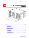
1
ADCP-90-216 Issue 2, January 1998 7-Inch Fiber Distribution System Splice Module User Manual Content Page INTRODUCTION ........................................................................... 1 Revision History ....................................................................... 1 List of Changes ....................................................................... 2 Trademark Information .................................................................. 2 Related Publications ................................................................... 2 Admonishments ....................................................................... 2 1. GENERAL ............................................................................ 3 2. FIBER DISTRIBUTION SYSTEM SPLICE MODULE ............................................. 3 3. FDS ACCESSORIES .................................................................... 3 4. DESCRIPTION......................................................................... 5 A. Chassis .......................................................................... 6 B. Front and Rear Covers .............................................................. 6 C. Splice Drawers ..................................................................... 7 5. INSTALLATION ........................................................................ 7 A. Unpack ........................................................................... 7 B. Chassis Installation ................................................................. 7 C. Cable Routing ..................................................................... 9 D. Fiber Storage ..................................................................... 12 E. Pigtails .......................................................................... 12 6. SPLICING ........................................................................... 13 7. SYSTEM INTEGRATION SERVICES ....................................................... 14 8. CUSTOMER SUPPORT SERVICES ........................................................ 15 INTRODUCTION This manual describes the ADC 7-Inch Fiber Distribution System (FDS) Splice Module. The Splice Module provides splicing and storage capabilities for the 7-Inch FDS. It contains physical and functional descriptions, installation, and operation information, and is intended for persons involved in installing and maintaining the fiber distribution system. The user of this manual must have a basic understanding of fiber optic terminology and concepts. Revision History ISSUE DATE REASON FOR CHANGE Issue 1 02/94 Original Issue 2 01/98 Update to reflect product changes and reformat to current standards. 1017825 Page 1 © 1998, ADC Telecommunications, Inc. ADCP-90-216 Issue 2, January 1998 List of Changes PAGE IDENTIFIER All pages – DESCRIPTION OF CHANGE Reformat to current standards with editorial and technical changes. Trademark Information The following trademarks are documented in this manual: FibrLok is a trademark of 3M Lucent is a registered trademark of Lucent Technologies, Inc. Related Publications Listed below are related manuals and their publication numbers. Copies of these publications can be ordered by contacting the ADC Technical Assistance Center at 1-800-366-3891 (in U.S.A. or Canada) or 612-946-3000, extension 3475 (outside U.S.A. and Canada). Title ADCP Number 7-Inch Fiber Distribution System Application Guide and User Manual 7-Inch Fiber Distribution System Equipment Rack Installation Instructions ADCP-90-198 ADCP-90-193 Admonishments Important safety admonishments are used throughout this manual to warn of possible hazards to persons or equipment. An admonishment identifies a possible hazard and then explains what may happen if the hazard is not avoided. The admonishments — in the form of Dangers, Warnings, and Cautions — must be followed at all times. These warnings are flagged by use of the triangular alert icon (seen below), and are listed in descending order of severity of injury or damage and likelihood of occurrence. Danger: Danger is used to indicate the presence of a hazard that will cause severe personal injury, death, or substantial property damage if the hazard is not avoided. Warning: Warning is used to indicate the presence of a hazard that can cause severe personal injury, death, or substantial property damage if the hazard is not avoided. Caution: Caution is used to indicate the presence of a hazard that will or can cause minor personal injury or property damage if the hazard is not avoided. Page 2 1998, ADC Telecommunications, Inc. ADCP-90-216 Issue 2, January 1998 1. GENERAL The ADC 7-Inch Fiber Distribution System (FDS) (Figure 1) provides the termination, 1.01 splicing, and storage requirements of a large fiber optic cable system. The splice module is compatible with the 7-Inch FDS or it can be used with or as a replacement for the Lucent LGX splice modules. The FDS is modular in design so that additional capacity and functions can be added as 1.02 the system requirements change. A 7-Inch FDS consists of these major components. • FDS Frame • FDS Splice Module • FDS Connector Module (72 terminations) • Accessories including vertical cable guides 2. FIBER DISTRIBUTION SYSTEM SPLICE MODULE The splice module permits splicing outside plant (OSP) or intrafacility fiber cable (IFC) 2.01 fibers to each other or to pigtail assemblies. The module provides a protective enclosure for mounting splices and for coiling the service loop required in the splicing process. The splice module can be used as a direct replacement for the LGX splice module and 2.02 can be installed in the same frame. 3. FDS ACCESSORIES Optional Interbay Management Panels (IMPs) are available for installation between 3.01 frames. The panels provide storage for patch cords between frames. Other accessories such as connector adapters, connector retainers, blank panels, and outside plant and intrafacility fiber cable clamp kits are available to complete the installation. Optional vertical cable guides can be attached at each side of the chassis (see Figure 2), 3.02 unless the splice module is installed in an ADC equipment frame which includes guides. The cable guides form a vertical pathway and provide protection and organization for patch cords. Four vertical cable guide styles are available. Their use is determined by frame spacing and whether they are used with the 7-Inch FDS or LGX frames. Choose one of the vertical cable guides that match what is installed on the other FDS equipment in the rack: • 2-inch/2-finger design - Used with LGX modules only, when no rack spacing is used and a retrofit IMP panel is installed. • 2-inch/2-finger design – Used with 7-Inch FDS modules when no rack spacing is used and a retrofit IMP is installed. • 4-inch/7-finger design – Used with 7-inch FDS modules when no rack spacing is used and an IMP is not installed, or when racks are spaced five inches apart and an IMP is used. • Rear vertical cable guide – Used in a cross-connect application, to organize and route fiber optic terminal (FOT) equipment patch cords to the rear of the module. Page 3 1998, ADC Telecommunications, Inc. ADCP-90-216 Issue 2, January 1998 Splice trays are available in nine configurations which provide splice chips to support 3.03 individual splices. See Table 1 for catalog numbers. OSP CABLE IFC CABLE INTERBAY MANAGEMENT PANEL CABLE GUIDES PIGTAILS CONNECTOR MODULE SPLICE MODULE 4117-A = TERMINATION = SPLICE Figure 1. 7-Inch FDS 2- OR 4-INCH (7-FINGERS) 7 FANNING FINGERS 4-INCH (7 FINGERS) 7 FANNING FINGERS 2-INCH (RETROFIT) 2 FANNING FINGERS REAR VERTICAL CABLE GUIDE 2 FANNING FINGERS 1200-A Figure 2. Optional Vertical Cable Guides Page 4 1998, ADC Telecommunications, Inc. ADCP-90-216 Issue 2, January 1998 4. DESCRIPTION The splice module requires a 7-inch (17.8 cm) mounting space within the frame. Major 4.01 components of the splice module are shown in Figure 3 and are described in the following paragraphs. Specifications for the module are listed in Table 1. PIGTAIL CABLE ACCESS OSP/IFC CABLE ACCESS 7.0 IN. 11.0 IN. 4118-A 17.0 IN. Figure 3. 7-Inch FDS Splice Module Components and Dimensions Page 5 1998, ADC Telecommunications, Inc. ADCP-90-216 Issue 2, January 1998 Table 1. Splice Module Specifications FEATURE SPECIFICATION Dimensions Height 7 in. (17.78 cm) Width 17 in. (43.18 cm) Depth 11 in. (27.94 cm) Mounting 19-inch or 23-inch rack Splice Details Splice Drawers 6 Splice Trays 12 (One or two splice trays per drawer) Catalog Number: Splice Chip Type: FST-F3DF-FT Bare Fusion FST-F3DF-HS Heat Shrink Fusion FST-F3DF-MT Mechanical (Elastomeric) FST-F3DF-RT Rotary FST-F3DF-3M FibrLok FST-F3DF-NT Qpak FST-F3DF-RC Raychem FST-F3DF-HS18 Heat Shrink Fusion (18 splices) FST-F3DF-HSAC Splice Capacity AOFR Clip 144 splices (12 splices per splice tray)* Cable Clamp Kits IFC/OSP Cable Clamp FL2-ACC007 Outside diameter 0.5-0.8 in. (13-20 mm) * Except where otherwise noted. A. Chassis The splice module chassis is constructed of heavy gauge aluminum and has a baked 4.02 powder paint finish. The module is compatible with the 7-inch FDS connector module. Cable access holes at the left and right side of both modules provide IFC or OSP cable fiber access. Fiber access holes in the top and bottom of both modules permit protected routing of pigtails to a connector module mounted either above or below the splice module. B. Front and Rear Covers A transparent front cover, hinged at the bottom, protects the fibers and pigtails from 4.03 normal activity near the module. The circuit designation labels provided are to be attached to the front of each splice drawer. Circuit identification can be written on labels and attached to the designation cards. The front cover can be removed for convenience and protection during installation or other activity. The metal rear cover is hinged at the bottom and is removable. The removable cover provides access to the interior of the chassis for fiber activity. Page 6 1998, ADC Telecommunications, Inc. ADCP-90-216 Issue 2, January 1998 C. Splice Drawers The splice module contains up to six splice drawers. Each splice drawer can handle two 4.04 ADC splice trays. Each ADC splice tray can handle 12 Fusion, heat shrink, mechanical (elastomeric), rotary, FibrLok, Qpak, AOFR clip, or Raychem splices using the appropriate splice chips. The FST-F3DF-HS18 splice tray can handle 18 heat shrink splices. Individual catalog numbers are shown in Table 1. 5. INSTALLATION This section describes how to install the splice module in the 7-Inch FDS or LGX frame. 5.01 The sequence of procedures is as follows: • Unpack and inspect • Chassis installation • Cable routing and termination • Fiber storage and splicing A. Unpack 5.02 Unpack and inspect the various components as follows: 1. Inspect the exterior of the shipping container(s) for evidence of rough handling that may have damaged the components in the container. 2. Unpack each container while carefully checking the contents for damage. 3. If damage is detected or if parts are missing, file a claim with the commercial carrier and notify ADC Customer Service. Save damaged cartons for inspection by the carrier. 4. Refer to the Customer Service section at the back of this instruction sheet for repair, replacement, and warranty information. 5. Save all shipping containers for use if the equipment requires shipment at a future date. B. Chassis Installation This procedure describes how to install the standard 7-inch FDS splice module in either 5.03 an ADC supplied frame or an LGX frame. 1. Release the latch on the front cover and open it about 2 inches (5 cm). 2. Lift the front cover from the hinges and place it where it will not be scratched or damaged. 3. The splice module brackets are installed for a 19-inch equipment rack. If a 23-inch equipment rack is being used, remove the brackets and install them with the short bracket side against the splice module side as shown in Figure 4. Note: If a vertical cable guide is installed on the frame, it must be removed before installing the splice module. Page 7 1998, ADC Telecommunications, Inc. ADCP-90-216 Issue 2, January 1998 4. If applicable, remove the vertical cable guide from each side of the frame position in which the splice module is being installed. 5. Place the splice module in its assigned position in the frame. 6. Insert two #12-24 screws supplied through the mounting bracket at each side of the chassis and in the frame as shown in Figure 4. 7. Install optional vertical cable guides or reinstall the removed guides (see Figure 5). 8. Re-attach the front cover. FRAME #12-24 SCREW (2 PLACES - BOTH SIDES) INTERBAY MANAGEMENT PANEL MOUNTING BRACKET Figure 4. Splice Module Installation in an Equipment Rack Page 8 1998, ADC Telecommunications, Inc. 1216-A ADCP-90-216 Issue 2, January 1998 VERTICAL CABLE GUIDE MOUNTING HOLES VERTICAL CABLE GUIDE INTERBAY MANAGEMENT PANEL VERTICAL CABLE GUIDE MOUNTING HOLES #12-24 SCREW (2 PLACES EACH SIDE) 1217-A Figure 5. Vertical Cable Guide Installation in an Equipment Rack C. Cable Routing Cable installation is performed from the rear side of the splice module. The OSP or IFC 5.04 cables are routed to the back of the module chassis from either above or below the module. The pigtails are routed to the connector module through the fiber access holes in the top and bottom of the chassis. Prior to splicing, all cables (OSP and IFC) are routed to and secured to the side of the splice 5.05 module using a cable clamp kit. A total of eight cable clamp positions are available at both sides of the chassis. To avoid congestion, OSP and IFC cables should be installed on opposite sides of the module. Cables should be clamped as close as possible to the splice module to which the fibers will be routed to reduce the length of cable sheath that needs to be stripped and cleaned. Page 9 1998, ADC Telecommunications, Inc. ADCP-90-216 Issue 2, January 1998 Danger: Infrared radiation is invisible and can seriously damage the retina of the eye. Do not look into the optical bulkhead of an operational transmitter, or into the launching (output) end of an active fiber. A clean, protective cap or hood MUST be immediately placed over any radiating bulkhead receptacle or optical fiber connector to avoid exposure to potentially dangerous amounts of radiation. This practice also helps prevent contamination of connectors and adapters. Strip the outer sheath of the cable to expose the inner fiber bundles. Clean the cable core 5.06 as necessary per local practice. The cable sheath must extend about 0.75 inches (1.9 cm) beyond the cable clamp. The service loop length shown in Figure 6 includes approximately 30 inches (76.2 cm) of fiber within the splice tray for splicing. If buffer tubes or fiber protector sleeves are needed add them at this time. CABLE CLAMP 0.75 IN. (1.9 CM) CABLE SHEATH FIBERS 13 FT. (4.0 M) RECOMMENDED SPLICES 4135-A Figure 6. Sheath Opening for OSP/IFC Cables Page 10 1998, ADC Telecommunications, Inc. ADCP-90-216 Issue 2, January 1998 One cable clamp kit is currently available. The OSP cable clamp kit accommodates 5.07 cables with outside diameters that range from 0.5 to 0.8 inches (13-20 mm). Select a grommet that when placed around the cable, has a gap of nearly 0 to 0.30 inches 5.08 (0 - 8 mm). The grommet is not required if the cable diameter is between 0.7 inch and 0.8 inches (1.78 cm and 2.03 cm). Assemble the cable clamp components as shown in Figure 7 and attach to the side of the 5.09 chassis (see Figure 3). If the cable is routed to the chassis from above, install the cable clamp in the upper part of the chassis. If the cable is routed to the chassis from below, install the cable clamp in the lower part of the chassis. Some outside plant cables are constructed with a metallic strength member or a metallic 5.10 inner sheath. Since OSP cables are exposed to electrical hazards, all metallic member OSP cables must be bonded to ground. Follow local practice using an approved sheath grounding kit connected to the #6 framework ground lead. GAP OF NEARLY ZERO TO 0.30 IN. (7.6 MM) WHEN PLACED AROUND CABLE. IF CABLE DIAMETER IS MORE THAN 0.70-IN. (17.8 MM) USE ONLY RUBBER CLAMP. IFC/OSP CABLE GROMMET CABLE CLAMP PLATE 1194-A Figure 7. Cable Clamp Assembly Page 11 1998, ADC Telecommunications, Inc. ADCP-90-216 Issue 2, January 1998 D. Fiber Storage Open the rear door about 2 inches (5 cm) and lift it from its hinges. Place the cover 5.11 where it will not be scratched or damaged. Route OSP/IFC fibers through a side access opening in the chassis to the assigned 5.12 drawer of the splice module. Service loop should be stored in the assigned drawer per Figure 8. Make sure to route fibers through the retaining ring in the back of the drawer. Passing the fibers through the retaining ring is required for the first pass only. The fiber bundles (service loop) should make three and one-half passes around the radius limiters and then be routed such that the end of the braided sleeve or protective sleeve occurs at a point between the two side radius limiters, noted as position “A” in Figure 8, and just onto the splice tray. Coil the fiber bundles around the four radius limiters, either counter-clockwise if entering the splice drawer from the right, or clockwise if entering the splice drawer from the left. E. Pigtails Individual fibers with a factory installed connector on one end should be bundled together 5.13 in groups (usually 12) and protected by a braided sleeve or loose tubing, and routed from the FDS connector module to the splice module splice drawer through fiber pass-through holes at the top or bottom of the module, depending on the location of the FDS connector module. Because the pigtails and IFC/OSP fiber bundles must form a single service loop to enter the 5.14 splice tray, both bundles must enter the splice module from the same side (either left or right side). OSP CABLE AT LEFT SIDE RETAINER CLIPS RADIUS LIMITER A A FIBERS 4132-A Figure 8. Fiber Routing in Splice Module Page 12 1998, ADC Telecommunications, Inc. ADCP-90-216 Issue 2, January 1998 6. SPLICING The splice module accommodates most splicing methods which should be performed in 6.01 accordance with local practices. The splice tray splice chip should be selected to match the local splice method. 6.02 Open the drawer and remove the splice tray while carefully uncoiling the service loop. Secure the fiber bundles to the splice tray with tie wraps as shown in Figure 9. The tie 6.03 wraps should secure the protective sleeve or jacket but must not pinch the fibers. Route the fibers on the splice tray as shown in Figure 9. The routing in the splice tray is 6.04 dependent on the fiber entry direction (either from the left or the right). 6.05 Splice using local practice. 6.06 When splicing is complete, snap the protective cover on the splice tray. 900 µ FIBERS SPLICE TRAY SPLICE CHIP SPLICE 250 µ FIBERS 3576-B IFC/OSP FIBER PIGTAIL BUNDLE CABLE TIES Figure 9. Fiber Routing in Splice Tray Page 13 1998, ADC Telecommunications, Inc. ADCP-90-216 Issue 2, January 1998 Coil the service loop clockwise (if the fiber entry is from the right) or counter-clockwise 6.07 (if the fiber entry is from the left), around the radius limiters in the splice drawer. Avoid twisting the service loop when coiling around the radius limiters. 6.08 Place the splice tray in the center of the drawer and push the drawer into the chassis. 6.09 Record the cable fiber identification on the designation label attached to the front cover. 6.10 Repeat steps 6.02 through 6.09 for additional splice trays as required. 7. SYSTEM INTEGRATION SERVICES ADC offers the following system integration services. For calls originating in the U.S.A. 7.01 or Canada, dial 1-800-366-3891, extension 3000. For calls originating outside the U.S.A. or Canada, dial 612-946-3000. Technical Assistance Center • • • • • • • • • • • Technical Training • Product Technology • Custom Designed Training Technical Operations • Detail Engineering • End-to-End Installation • Drafting Services Page 14 1998, ADC Telecommunications, Inc. Product Management Project Engineering Project Administration Network Design Broadband Design (RF Design and Strand Mapping) Integration Network Testing Network Monitoring (Upstream or Downstream) Power Monitoring Remote Surveillance System Turn-Up and Test Service/Maintenance Agreements ADCP-90-216 Issue 2, January 1998 8. CUSTOMER SUPPORT SERVICES 8.01 ADC offers the following customer support services. For calls originating in the U.S.A. or Canada, dial 1-800-366-3891, then request the extension listed. For calls originating outside the U.S.A. or Canada, dial 612-946-3475 or 612-946-3000. BCG Technical Assistance Center Extension 3475 E-Mail: [email protected] • • • • • • • • Technical Information System/Network Configuration Product Specification Product Application Training Installation and Operation Assistance Troubleshooting and Repair Field Assistance Sales Administration Extension 3000 • • • • Quotation Proposals Ordering Delivery General Product Information Product Return Department Extension 3000 E-Mail: repair&[email protected] • ADC Return Authorization number and instructions must be obtained before returning products. 8.02 Product information and service can also be obtained by writing ADC Telecommunications, Inc., P.O. Box 1101, Minneapolis, Minnesota 55440-1101, U.S.A. Contents herein are current as of the date of publication. ADC reserves the right to change the contents without prior notice. In no event shall ADC be liable for any damages resulting from loss of data, loss of use, or loss of profits and ADC further disclaims any and all liability for indirect, incidental, special, consequential or other similar damages. This disclaimer of liability applies to all products, publications and services during and after the warranty period. This publication may be verified at any time by contacting ADC’s Technical Assistance Center at 1-800-366-3891, extension 3223 (in U.S.A. or Canada) or 612-946-3223 (outside U.S.A. and Canada), or by writing to ADC Telecommunications, Inc., Attn: Technical Assistance Center, Mail Station #77, P.O. Box 1101, Minneapolis, MN 55440-1101, U.S.A. © 1998, ADC Telecommunications, Inc. All Rights Reserved Printed in U.S.A. Page 15