1
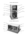
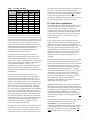
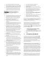
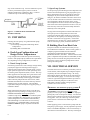
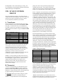
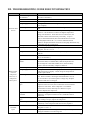
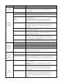
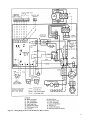
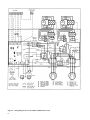
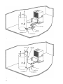
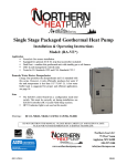
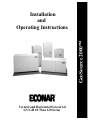
GeoSource 2000 Installation and Operating Instructions Vertical and Horizontal Forced Air GV/GH 18 Thru 120 Series GeoSource 2000 Vertical Unit Air Filter Blower Air Coil Contactor Transformer Expansion Valve Controller Scroll Compressor Reversing Valve Desuperheater (Optional) Air Pad GeoSource 2000 Horizontal Unit Controller Air Coil Reversing Valve Blower Transformer Scroll Compressor Contactor Air Pad TABLE OF CONTENTS Section Title Page I. Introduction to ECONAR Heat Pumps . . . . . . . . . . . . . . . . . . . . . 2 II. Unit Location/Mounting . . . . . . . . . . . . . . . . . . . . . . . . . . . . . . . . . 2 III. Duct System/Blower . . . . . . . . . . . . . . . . . . . . . . . . . . . . . . . . . . . . 2 IV. Earth Loop Water Piping . . . . . . . . . . . . . . . . . . . . . . . . . . . . . . . . 4 A. Closed Loop Applications B. Open Loop Applications 1) Open Loop Freeze Protection Switch 2) Water Coil Maintenance a. Freeze Cleaning b. Chlorine Cleaning c. Miratic Acid Cleaning V. Condensate Drain . . . . . . . . . . . . . . . . . . . . . . . . . . . . . . . . . . . . . . 7 VI. Unit Sizing . . . . . . . . . . . . . . . . . . . . . . . . . . . . . . . . . . . . . . . . . . . . 8 A. Earth Loop Configuration and Design Water Temperatures B. Building Heat Loss/Heat Gain VII. Electrical Service . . . . . . . . . . . . . . . . . . . . . . . . . . . . . . . . . . . . . . . 8 VIII. 24 Volt Control Circuit . . . . . . . . . . . . . . . . . . . . . . . . . . . . . . . . . . 9 A. Transformer B. Thermostat C. Controller 1) Blower Operation 2) Earth Loop Pump Initiation 3) Compressor Operation 4) 4-Way Valve Control 5) Compressor Lockouts 6) Compressor Anti-Short-Cycle 7) System Diagnostics 8) Overflow Detection IX. Startup . . . . . . . . . . . . . . . . . . . . . . . . . . . . . . . . . . . . . . . . . . . . . . . 11 X. Service . . . . . . . . . . . . . . . . . . . . . . . . . . . . . . . . . . . . . . . . . . . . . . . . 11 A. Filter B. Lockout Lights C. Preseason Inspection XI. Thermostat Operation . . . . . . . . . . . . . . . . . . . . . . . . . . . . . . . . . . 12 XII. Troubleshooting Guide For Unit Operation . . . . . . . . . . . . . . . . . 13 XIII. Troubleshooting Guide For Lockout Conditions . . . . . . . . . . . . . 15 XIV. Additional Figures and Tables . . . . . . . . . . . . . . . . . . . . . . . . . . . . 16 XV. Desuperheater (Optional) . . . . . . . . . . . . . . . . . . . . . . . . . . . . . . . . 19 1 I. INTRODUCTION TO ECONAR HEAT PUMPS ECONAR Energy Systems, Corp. has been producing geothermal heat pumps in Minnesota for over fifteen years. The cold winter climate has driven the design of ECONAR Energy System's heating and cooling equipment to what is known as a "Cold Climate" geothermal heat pump . This cold climate technology focuses on maximizing the energy savings available in heating dominated regions without sacrificing comfort. Extremely efficient cooling, dehumidification and optional domestic hot water heating are also provided in one neatly packaged system. Geothermal heat pumps get their name from the transfer of heat to and from the earth. The earth coupled heat exchanger (geothermal loop) supplies the source energy for heating and absorbs the discharged energy from cooling. The system uses a compression cycle, much like your refrigerator, to collect the earth's energy supplied by the sun and uses it to heat your home. Since the process only moves heat and does not create it, the efficiencies are three to four times higher than the most efficient fossil fuel systems. ECONAR produces three types of GeoSource 2000 heat pumps: forced air heat pumps, which transfer heat from water to air; hydronic heat pumps, which transfer heat from water to water; and combination heat pumps, which incorporate the hydronic heating of a water to water unit into a forced air unit. This guide discusses the forced air unit. Safety and comfort are both inherent to, and designed into ECONAR Energy System's geothermal heat pumps. Since the system runs comp letely on electrical energy, your entire home can have the safety of being gas free. The best engineering and quality control is built into every ECONAR heat pump built. Proper application and correct installation will assure excellent performance and customer satisfaction. ECONAR's commitment to quality is written on the side of every heat pump we build. Throughout the building process the technicians that build each unit sign their names to the quality assurance label after completing their inspections. As a final quality test, every unit goes through a full run test where the performance and operation is verified in both the heating and cooling modes. No other manufacturer goes as far as to run a full performance check to assure system quality. ** IMPORTANT** Service of refrigerant based equipment can be hazardous due to system pressure and 230 volt electrical energy. Only trained or qualified service personnel can install, repair or service refrigerant equipment. 2 N Warning - Turn off the main switches before performing service or maintenance to this unit. Electrical shock can cause personal injury. The installer is responsible to see that all local electrical, plumbing, heating and air conditioning codes are followed. II. UNIT LOCATION/ MOUNTING Locate the unit in an indoor area where the ambient temperature will remain above 45o F. Servicing of the heat pump is done primarily from the front. Rear access is desirable and should be provided when possible. A field installed drain pan is required under the entire unit where accidental water discharge could damage surrounding floors, walls or ceilings. I CAUTION –Do not tip units on their side during transportation or installation, or severe internal damage may occur. Units must be mounted on a vibration-absorbing pad slightly larger than the base to provide isolation between the unit and the floor. Water supply pumps should not be hard plumbed directly to the unit with copper pipe; this could transfer vibration from the water pump to the refrigeration circuit, causing a resonating sound. Hard plumbing could also transfer vibration noise from the unit through the piping to the living space. I CAUTION - Before driving screws into the cabinet, check on the inside of the unit to be sure the screw will not hit electrical or refrigeration lines. III. DUCT SYSTEM/BLOWER For the duct system, metal ductwork should be used. Flexible connectors are required for discharge and return air duct connections on a metal duct system. For acceptable duct sizes, see Table 1. If the duct system is installed in an uninsulated space, the metal ductwork should be insulated on the outside to prevent heat loss and to absorb noise. If the unit is connected to existing ductwork, this ductwork must have the capacity to handle the air volume required by the heat pump. Undersized duct work will cause noisy operation and poor operating efficiencies due to lack of airflow. The GeoSource 2000 forced air heat pumps use a 230 Volt three speed blower. For maximum airflow, the blower should be on high speed. Moving the wire on the fan terminal strip can change the fan speed. For blower data and factory settings, see Table 2. F Note: The blower will not operate properly if ductwork is not attached. The ductwork supplies static pressure to give the blower motor a load to work against. Blower motors may overheat if run for an extended period of time without ductwork attached. Table 1 - Duct Sizing Chart CFM 50 75 100 150 200 250 300 350 400 450 500 600 800 1000 1200 1400 1600 1800 2000 2200 Acceptable Branch Duct Sizes Round Rectangular 4" 4x4 5" 4x5, 4x6 6" 4x8, 4x6 7" 4x10, 5x8, 6x6 8" 5x10, 6x8, 4x14, 7x7 9" 6x10, 8x8, 4x16 10" 6x14, 8x10, 7x12 10" 6x20, 6x16, 9x10 12" 6x18, 10x10, 9x12 12" 6x20, 8x14, 9x12, 10x11 Acceptable Main or Trunk Duct Sizes Round Rectangular 10" 10" 10" 12" 12" 14" 16" 16" 18" 20" 20" 22" 4x20, 7x10, 6x12, 8x9 5x20, 6x16, 9x10, 8x12 10x10, 6x18, 8x12, 7x14 6x20, 7x18, 8x16, 10x12 8x18, 9x15, 10x14, 12x12 10x18, 12x14, 8x24 10x20, 12x18, 14x15 10x25, 12x20, 14x18, 15x16 10x30, 15x18, 14x20 10x35, 15x20, 16x19, 12x30, 14x25 10x40, 12x30, 15x25, 18x20 10x45, 15x28, 18x22, 20x20 Tables calculated for 0.05 to 0.10 inches of water friction per 100’ of duct. At these duct design conditions, along with the pressure drop through the filter, the total design external static pressure is 0.20 inches of water. Normal airflow at 0.20 inches of water should then be used for these calculations. Table 2 - Fan Performance Data UNIT SIZE GV/GH/180/181 GV/GH/230/231 GV/GH/290/291 GV/GH/360/361 GV/GH/420/421 GV/GH/520/521 GV/GH/590/591 GV/GH/670/671 GH980 GH1200 FAN SPEED Low Medium High* Low Medium High* Low Medium High* Low Medium* High Low Medium High* Low Medium High* Low Medium High* Low Medium* High Low Medium High* Low Medium High* 0.10 550 610 675 760 860 950 870 980 1090 1005 1140 1210 1005 1140 1210 1325 1505 1685 1500 1700 1900 1900 2220 2410 2510 2840 3040 3020 3220 3530 0.15 520 580 650 710 800 900 825 935 1050 965 1100 1150 965 1100 1150 1275 1450 1625 1450 1645 1850 1850 2185 2370 2390 2720 2920 2940 3140 3430 External 0.20 490 550 625 680 775 870 800 900 1000 935 1065 1110 935 1065 1110 1235 1415 1550 1410 1595 1800 1800 2150 2325 2270 2600 2800 2860 3060 3340 Static Pressure - in WG 0.25 0.30 0.35 460 445 430 530 510 480 600 580 560 650 625 600 750 735 710 855 830 800 775 750 735 870 845 830 965 940 920 890 855 815 1010 965 935 1070 1030 985 890 855 815 1010 965 935 1070 1030 985 1200 1165 1135 1375 1320 1275 1500 1435 1405 1360 1325 1310 1555 1500 1480 1740 1680 1625 1750 1690 1660 2110 2050 2000 2250 2200 2150 2200 2110 2070 2520 2430 2380 2730 2640 2590 2780 2710 2650 2970 2900 2890 3260 3170 3100 0.40 410 460 525 580 650 760 710 800 865 805 915 960 805 915 960 1105 1245 1360 1250 1410 1590 1600 1960 2110 2030 2330 2550 2600 2800 3040 0.50 385 440 480 560 590 720 650 760 840 740 840 895 740 840 895 1055 1185 1305 1210 1380 1510 1560 1880 2030 1980 2280 2480 2550 2710 2960 *Denotes Factory Setting 3 IV. EARTH LOOP WATER PIPING area, soil type, and individual capacity requirements. Contact your local installer or ECONAR’s Customer Support for loop sizing requirements in your area. Since water is the source of energy in the wintertime and the energy sink in the summertime, good water supply is possibly the most important requirement of a geothermal heat pump system installation. There are two common types of water supplies, closed loop systems and open loop systems. Since normal wintertime operating entering water temperatures (EWT) to the heat pump are from 25o F to 32o F, the solution in the earth loop must include antifreeze. GTF and propylene glycol are common antifreeze solutions. GTF is methanol-based antifreeze, which should be mixed 50% with water to achieve freeze protection of 10o F. Propylene glycol antifreeze solution should be mixed 25% with water to obtain a 15o F freeze protection. DO NOT mix more than 25% propylene glycol with water in an attempt to achieve a lower than 15o F freeze protection, since more concentrated mixtures of propylene glycol become too viscous at low temperatures and cannot be pumped through the earth loop. Insufficient amounts of antifreeze may result in a freeze rupture of the unit, and can cause unit shutdown problems during cold weather operation (when the heat pump experiences the longest run time) due to loop temperatures falling below the freeze protection of the loop solution. A. Closed Loop Applications A closed loop system recirculates the same water/antifreeze solution through a closed system of underground high-density polyethylene pipe. As the solution passes through the pipe, it collects heat (in the heating mode) that is being transferred from the relatively warm surrounding soil through the pipe and into the relatively cold solution. The solution is circulated to the heat pump, which pulls heat out of the solution, and then back through the ground to extract more heat from the earth. The GeoSource 2000 is designed to operate on either vertical or horizontal closed loop applications. Vertical loops are typically installed with a well drilling rig up to 200 feet deep or more. Horizontal systems are typically installed with excavating or trenching equipment approximately six to eight feet deep, depending on geographic location and length of pipe used. Earth loops must be sized properly for each particular geographic Figure 1 – Closed Loop Water Plumbing 4 Flow rate requirements for closed loops are higher than open loop systems because water temperatures supplied to the heat pump are generally lower (see Table 3). Between 2.5 to 3.0 gallons per minute (GPM) per ton are required for proper operation of the heat pump and the earth coupled heat exchanger. Table 3 – Loop Side Flow Rates Model Closed Loop Flow dP (gpm) (psi) G(V,H)18 4 0.9 G(V,H)23 6 3.0 G(V,H)29 7 3.9 G(V,H)36 8 5.5 G(V,H)42 10 7.8 G(V,H)52 11 5.2 G(V,H)59 13 6.0 G(V,H)67 14 7.0 G(V,H)98 22 3.8 G(V,H)120 26 4.5 Open Loop Flow dP (gpm) (psi) 2 0.9 3 0.9 4 1.5 4 1.3 5 1.7 6 1.6 9 3.1 10 3.8 12 2.5 16 3.0 Pressure/Temperature (P/T) ports should be installed in the entering and leaving water lines of the heat pump on a closed loop system (see Figure 1). A thermometer can be inserted into the P/T ports to check entering and leaving water temperatures. A pressure gauge can also be inserted into these P/T ports to determine the pressure differential between the entering and leaving water. This pressure differential can then be compared to the specification data on each particular heat pump to determine the flow rate of the system. A PumpPAK that is individually sized for each application can supply pumping requirements for the earth loop fluid. The PumpPAK can also be used to purge the loop system. The PumpPAK is wired directly to the contactor and operates whenever the compressor runs (see Electrical Diagram – Figure 5). If a PumpPAK is not used, a separate pump can be used which is energized with a pump relay (note: electrical code will require a fused disconnect for pumps other than PumpPAKs). Filling and purging a closed loop system are very important steps to assure proper heat pump operation. Each loop must be purged with enough water flow to assure a two feet per second flow rate in each circuit in the loop. This normally requires a 1½ to 3 HP high head pump to circulate fluid through the loop to remove all the air out of the loop and into a purging tank. Allow the pump to run 10 to 15 minutes after the last air bubbles have been removed. Enough antifreeze must be added to give a 10o F to 15o F freeze protection to the earth loop system. This amount should be calculated and added to the loop after purging is complete. After antifreeze has been installed it should be measured with a hydrometer, refractometer or any other device to determine the actual freezing point of the solution. Remember that a low antifreeze level will lock the heat pump out on low pressure during wintertime operation. The purge pump can be used to pressurize the system to an initial static pressure of 30-40 psi. Make sure the system is at this pressure after the loop pipe has had enough time to stretch. In order to achieve the 30 to 40 psi initial pressure, the loop may need to be pressurized to 60 to 65 psi. This static pressure will fluctuate from heating to cooling season, but the pressure should always remain above zero so circulation pumps do not cavitate and air cannot be pulled into the system. ( For information regarding earth loop installations contact your local installer, distributor or factory representative. B. Open Loop Applications An open system gets its name from the open discharge of water after it has been used by the heat pump. A well must be available that can supply all of the water requirements (see Table 3) of the heat pump along with any other water requirements drawing off that same well. The well must be capable of supplying the heat pump’s required flow rate for up to 24 hours per day on the coldest winter day. Figure 2 shows the necessary components for water piping of an open system. First, a bladder type pressure tank with a "draw down" of at least 1½ times the well pump capacity must be installed on the supply side of the heat pump. Shut off valves and boiler drains on the entering and leaving water lines are necessary for future maintenance issues. A screen strainer is placed on the supply line with a mesh size of 40 or 60 and enough surface area to allow for particle buildup between cleanings. Pressure/Temperature (P/T) ports are placed in the supply and discharge lines so that thermometers or pressure gauges can be inserted into the water stream. On the well water discharge side of the heat pump, a flow control valve must be mounted next to the heat pump to regulate the maximum water flow through the unit. A solenoid valve is then installed and wired to the accessory plug on the controller. This valve will open when the unit is running and close when the unit stops. A visual flow meter is then installed to allow visual inspection of the flow requirements. The flow meter is useful in determining when maintenance is required. (If you can't read the flow, cleaning is required.) Schedule 40 PVC piping, copper tubing, polyethylene or rubber hose can be used for supply and discharge water lines. Make sure line sizes are large enough to supply the required flow with a reasonable pressure drop (generally 1" diameter minimum). NOTE: Do not use plastic female fittings with metal male fittings, or fractures may result in the female fittings. Always use plastic male into steel female! Water discharge is generally made to a drain field, stream, pond, surface discharge, tile line, or storm sewer. I CAUTION: Using a drain field requires soil conditions and adequate sizing to assure rapid percolation, or the required flow rates will not be achieved. Consult local codes and ordinances to assure compliance. DO NOT discharge water to a septic system. 5 Figure 2 – Open Loop Water Plumbing The heat pump should never be operated with flow rates less than specified. Low flow rates or no flow may result in freezing water in the water to refrigerant heat exchanger. This will cause the unit to shut down on lowpressure lockout. If the unit locks out, verify that the unit has the required flow and reset the unit by shutting off power to the unit for one minute. I DO NOT continually reset the unit, if the unit locks out more than once call your service professional. ( Continued reset of the unit can freeze water inside the water coil to the point of rupturing the water coil. 1. Open Loop Freeze Protection Switch Heat pump installations on open loop systems, using a non-antifreeze protected water source during the heating mode, require the use of a freeze protection switch. If the water supply to the heat pump is interrupted for any reason, continued operation of the compressor would cause the water remaining in the water-to-refrigerant heat exchanger to freeze and rupture the copper inner tube. The freeze protection switch (ECONAR Part # 75-1028) will shut the unit down before freezing can occur and protect the heat pump against loss of flow. A freeze protection switch must be field installed on open loop GeoSource 2000 heat pumps before the warranty can be registered on the heat pump. The switch mounts on the compressor’s suction line and is wired to terminals on the controller (from X to FP). After the freeze protection switch is installed, the J4 jumper must be removed from the controller to activate the switch. The low pressure switch now locks the unit off at 35 psi pressure in the heating mode. 6 2. Water Coil Maintenance Water quality is a major concern for open systems. Problems can occur from scaling, particle buildup, suspended solids, corrosion, pH levels outside the 7-9 range, or biological growth. If poor water quality is known to exist in your area, a cupro-nickel water coil may be required when ordering the system, or installing a closed loop system may be the best alternative. Water coil cleaning on open loop systems may be necessary on a regular basis. Depending on the specific water quality issue, the water coil can be cleaned by the following methods: a. Freeze Cleaning (Scale deposits, particle buildup) I. Before using the freeze cleaning procedure, verify that it needs to be done. Answer the following questions to determine if servicing is required. 1. Determine and verify that the required water flow rate in GPM is both present and correct. 2. Determine the temperature differential of the water. Under normal conditions, there should be a temperature difference of about 10-15 degrees between the supply side and discharge side. If the temperature difference is 8 degrees or less, consideration should then be given to cleaning the water coil heat exchanger. II. If cleaning of the water coil is indicated, please carefully follow the steps listed below to utilize the freeze cleaning method. 1. 2. 3. Turn off the heat pump and its water supply. Open a plumbing connection on the water supply side, if possible, to break the system vacuum and allow easier drainage of the system and water coil. Drain the water out of the system and water coil via the boiler drains on the entering and leaving water lines, and the drain on the heat exchanger. N WARNING!! N FAILURE TO COMPLETELY DRAIN THE WATER COIL HEAT EXCHANGER COULD POSSIBLY RESULT IN A FREEZE RUPTURE! 4. 5. 6. 7. 8. 4. Set the thermostat to "Heat" to start the heat pump in the heating mode and quickly freeze the coil. 5. Allow the heat pump to run until it automatically shuts off on low pressure and then turn the thermostat to the "Off" position. 6. Recap the water coil drain and tighten any plumbing connections that may have been loosened. 7. If so equipped, open the field installed drain cock on the water discharge side of the heat pump, and install a short piece of rubber hose to allow drainage into a drain or bucket. A drain cock on the discharge side allows the water flow to bypass the solenoid valve, flow valve, flow meter, or any other item that may be clogged by mineral debris. Drainage to a bucket helps prevent the clogging of drains and allows you to visually determine the effectiveness of the procedure. 8. Turn on the water supply to the heat pump in order to start the process of flushing any mineral debris from the unit. 9. Set the thermostat to "Cool" and start the heat pump in the cooling mode to quickly thaw out the water coil. 10. Run the heat pump until the water coil is completely thawed out and any loosened scale, mineral deposits, or other debris buildup is flushed completely from the water coil. Allow at least 5 minutes of operation to ensure that the water coil is thoroughly thawed out. 11. If the water still contains mineral debris, and if the flow through the unit did not improve along with an increase in the temperature difference between the water supply and discharge, repeat the entire procedure listed above. 12. Reset the heat pump for normal operation. 1. 2. 3. b. Chlorine Cleaning (Bacterial Growth) Turn the thermostat to the "Off" position. Connect a submersible circulating pump to the hose bibs on the entering and leaving water sides of the heat exchanger. Submerse the pump in a five-gallon pail of water and chlorine bleach mixture. The chlorine should be strong enough to kill the bacteria. Suggested initial mixture is 1 part chlorine bleach to 4 parts water. 9. Close the shut off valves upstream and downstream of the heat exchanger. Open the hose bibs to allow circulation of the bleach solution. Start the pump and circulate the solution through the heat exchanger for 15 minutes to one hour. The solution should change color to indicate the chlorine is killing the bacteria and removing it from the heat exchanger. Flush the used solution down a drain by adding a fresh water supply to the pail. Flush until the leaving water is clear. Repeat this procedure until the solution runs clear through the chlorine circulation process. Flush the entire heat pump system with water. This procedure can be repeated annually, semiannually, or as often as it takes to keep bacteria out of the heat exchanger, or when bacteria appears in a visual flowmeter to the point the flow cannot be read. Another alternative to bacteria problems is to shock your entire well. Shocking your well may give longer term relief from bacteria problems than cleaning your heat exchanger, but will probably need to be repeated, possibly every three to five years. ( Contact a well driller in your area for more information. 1. 2. V. c. Miratic Acid Cleaning (Difficult Scaling and Particle Buildup Problems) Consult installer due to dangerous nature of acids. Iron out solutions and de-scaling products are also useful. CONDENSATE DRAIN Condensate traps are built into every GeoSource 2000 vertical unit, so an external trap should not be installed. Vertical units must be level to insure proper condensate drainage. Horizontal units require an external condensate trap in order to drain water from the heat pump. Horizontal units must also be mounted level in order for the condensate to drain. The condensate line as it leaves the U bend of the condensate trap must be at least 3” below the base of the heat pump. This requires the U bend to be 6” below the unit to give the upward portion of the U bend a 3” lift. The condensate trap should be vented after the U bend. The condensate line should be pitched away from the unit a minimum of 1/8” per foot. If the unit produces an odor in the cooling mode, the condensate trap or line may be plugged, or the unit may not be pitched correctly. Bleach may be poured down the condensate drain in the heat pump to kill any bacterial growth in the condensate line. Downflow units also require an external condensate trap. A stand is required underneath a downflow unit, since placing the unit on the floor would not allow for the 6” 7 drop of the condensate trap. Vented condensate traps are necessary to break the negative pressure in the air chamber and allow the condensate to flow. Construct condensate traps to the following diagram. 2. Open Loop Systems Figure 3 – Condensate Drain - Horizontal and Downflow Units Only Varying well water temperatures will have little effect on unit capacity in the cooling mode (since the well is connected to the heat pump condenser), but can have large effects on the capacity in the heating mode (since the well is connected to the evaporator). If well water temperatures are to exceed 70o F, special considerations, such as closed loop systems, should be addressed. VI. UNIT SIZING Selecting the unit capacity of a geothermal heat pump requires two things: A) Earth Loop Configuration and Design Water Temperatures. B) Building Heat Loss/Heat Gain. A. Earth Loop Configuration and Design Water Temperatures Loop configurations include the open and closed loop varieties. Heat pump capacity and flow rate requirements vary depending on loop configuration (see Table 3). On an open loop system the design water temperature will be the well water temperature in your geographic region. Many cold climates are in the 50o F range for well water temperature. If your well water temperatures are lower than 50o F, for instance Canadian well water can be as low as 43o F, the flow rate must be increased to avoid leaving water temperatures below the freezing point. If well water temperatures are above 50o F, as in some southern states where well water temperatures are above 70o F, the flow rates may need to be increased to dump heat more efficiently in the cooling mode. B. Building Heat Loss/Heat Gain The space load must be estimated accurately for any successful HVAC installation. There are many guides or computer programs available for load estimation including the ECONAR GeoSource Heat Pump Handbook, Manual J, and others. After the heat loss/heat gain is completed and loop EWT are established, the heat pump can now be selected using the specifications data. Choose the capacity of the heat pump based on both heating and cooling load. 1. Closed Loop Systems Closed loop systems use a heat exchanger of high density polyethylene pipe buried underground to supply a tempered water solution back to the heat pump. Closed loops operate at higher flow rates than open loops since the entering water temperature (EWT) is lower. The loop EWT supplied to the heat pump has a great effect on the capacity of the unit in the heating mode. Earth loops in cold climates are normally sized to supply a wintertime EWT to the heat pump from 32o F down to 25o F, which minimizes the installation cost of the earth loop and still maintains proper system operation. The unit GPM requirements and pressure drops for loop pump sizing is available in Table 3. VII. ELECTRICAL SERVICE When selecting the heat pump, choose a unit that will supply the necessary heating or cooling capacity at the minimum and maximum earth loop temperature conditions respectively. Example; if a residential system requires 45,000 Btu/hr to heat a house on an earth loop system (designed for 32o F minimum wintertime EWT), and 36,000 Btu/hr to cool the house on an earth loop (designed for 77o F summertime EWT), a Gx52x-x-Txxx GeoSource 2000 heat pump is required to handle the loads. I CAUTION: Three-phase units MUST be wired 8 The main electrical service must be protected by a fuse or circuit breaker, and be capable of providing the amperes required by the unit at nameplate voltage. All wiring shall comply with the national electrical code and/or any local codes that may apply. Access to the line voltage contactor is gained through the knockouts provided on either side of the heat pump next to the front corner. Route EMT or flexible conduit with appropriate 3conductor wire to the contactor. N WARNING - The unit must be properly grounded! N properly to insure proper compressor rotation. Improper phasing may result in compressor damage. An electronic phase sequence indicator must be used to check supplywiring phase. Also, the “Wild” leg of the three-phase power must be connected to the middle leg on the contactor. When supplying power to external water pumps with the heat pump’s power supply, use only impedance protected motors. ECONAR PumpPAKs can be wired directly to the contactor in the electrical box. The relay will energize the PumpPAK with a call for heating or cooling. The use of impedance protected pumps eliminates the need for additional fusing on the PumpPAK. VIII. 24 VOLT CONTROL CIRCUIT The wiring diagrams in Figures 5 and 6 shows the low voltage controls of the heat pump. This section will break down the three basic components of the low voltage circuit; transformer, thermostat, and controller. A. Transformer Electrical diagrams are provided in Figures 5 and 6 and on the electrical box cover panel of the GeoSource 2000 heat pump. An internal 24-volt, 55 VA transformer is provided to operate all control features of the heat pump. Table 4 shows the transformer usage for GeoSource 2000 heat pumps. Table 4 – Transformer Usage (VA) Component Contactor 4-Way Valve Controller Thermostat Blower Relay Electric Heat Relay (optional) Total Available 18-67 7 4 2 1 6 6 26 29 98-120 7x2 4 2 1 6x2 NA 33 22 If any system’s external controls require more than the VA available for external use from the transformer, a separate transformer must be used. The heat pump's transformer can generally power simple external control systems consisting of a few relays or a zone valve (depending, of course, on the VA draw of the components). On more complicated control systems the transformers capacity is used up very quickly. F Note: For units operating on 208V electrical service, the transformer must be switched to the correct lead (see electrical diagram – Figures 5 and 6). Units are factory shipped with the transformer set for 240V service. Operating a unit on 208V with the transformer set to 240V will cause the unit to operate with lower than normal control voltages. B. Thermostat A 2-heat/1-cool thermostat is recommended for proper operation of GeoSource 2000 heat pumps. Eight wire thermostat cable is required for proper operation of the thermostat. Consult the instructions in the thermostat box for proper mounting and thermostat operation. I CAUTION- miswiring of control voltage on system controls can result in fuse or transformer burnout. F Note: If a single thermostat controls multiple heat pumps, the control wiring of the heat pumps must be isolated from each other. This will prevent the heat pumps from receiving high voltage through the common wiring if it is turned off at the circuit breaker for service. Power is supplied to the thermostat by connecting the R and X terminals to the heat pump terminal strip. The fan is controlled through the G terminal and will operate continuously in the FAN ON position or when the compressor is running in the FAN AUTO position. The Y terminal energizes the compressor. The unit is put into the air conditioning mode when the thermostat energizes the O terminal, which operates the 4-way reversing valve. A lockout condition is indicated by the L terminal, which lights a red light on the thermostat (depending on the thermostat). This lockout condition means that the unit has shut itself down on a low or high-pressure switch to protect itself, and will not come back on until power has been reset to the heat pump. If a lockout condition exists, the heat pump should not be reset more than once. A service technician should be called immediately. Repeated reset can cause damage to the system. If second stage heating (e.g. electronic resistance strip heat) is used, its control wiring is connected to X and W2 on the heat pump terminal strip. Fan interlock relays are not required since the thermostat energizes the blower whenever the second stage is calling. W2 on the terminal strip is wired directly to second stage heating on the thermostat. In the event of a heat pump shutdown, switching the thermostat to emergency heat energizes the E terminal, which runs the blower and second stage heater but does not energize the compressor. The thermostat will indicate whenever second stage heating is energized. These wiring connections are listed in Table 5. Table 5 – Wiring Connections Function Terminal Strip 24 Volt Power R Common X Blower G Reversing Valve O 1st Stage Heat/Cool Y1 Lockout Signal L 2nd Stage Heat W2 Emergency Heat E Thermostat R C(X) G O Y1 L W2 E Use of a programmable setback thermostat in conjunction with a geothermal heat pump and a second stage backup electric resistance heater has the potential to cause inefficiency. The energy savings supplied by night setback could be less than the energy used by the electric elements if they operate in the morning to warm the space to the daytime temperature setting. Second stage usage should be monitored and setbacks adjusted to maximize energy savings of the entire system. F Note: If the thermostat is provided by others and is equipped with an anticipator, it should be set to its highest setting to avoid interfering with heat pump operation. 9 The anticipator has the effect of reducing system capacity by restricting run time. The thermostat should never be set back to less than 60o F. Air temperatures less than 60o F to the heat pump in residential applications can cause difficult starting conditions and lock the unit out. Commercial applications can be designed to use lower entering air temperatures, but 60o F is a safe low operating point in residential applications. C. Controller The controller receives a signal from the thermostat and initiates the correct sequence of operation for the heat pump. The controller performs the following functions: 1) Blower Operation 2) Earth Loop Pump Initiation 3) Compressor Operation 4) 4-Way Valve Control 5) Compressor Lockouts 6) Compressor Anti-Short-Cycle 7) System Diagnostics 8) Overflow Detection 1. Blower Operation A signal on the G terminal from the thermostat to the controller will tell the controller to energize the blower. The controller then energizes its G output to send control voltage directly to the blower motor relay. To change blower speeds, move the wire on the fan terminal strip to the desired setting. Changing the speed from the factory setting can cause problems with output air temperature or reduced airflow, locking out the unit. 2. Earth Loop Pump Initiation If a PumpPAK is used, it should be wired directly to the contactor of the compressor. If a PumpPAK is not used, a separate pump can be used which is energized with a pump relay (Note: electrical code will require a fused disconnect for pumps other than PumpPAKs ). When there is a call for an M1 output from the controller, the contactor will energize, starting the compressor and earth loop pump. 5. Compressor Lockouts A compressor lockout occurs if the high-pressure, low pressure (in heating mode), or freeze protection pressure switches open. The controller blocks the signal from the thermostat to the contactor that normally would energize the compressor. In the event of a compressor lockout the controller will send a signal from L on the terminal strip to an LED on the thermostat to indicate a lockout condition. This lockout condition means that the unit has shut itself down to protect itself, and will not come back on until power has been disconnected (via the circuit breaker) to the heat pump for one minute. Problems that could cause a lockout situation include: 1. Water flow or temperature problems 2. Air flow or temperature problems 3. Internal heat pump operation problems 4. Cold ambient air temperature conditions ( If a lockout condition exists, the heat pump should not be reset more than once; a service technician should be called immediately. I The cause of the lockout must be determined. Repeated reset may cause damage to the system. 6. Compressor Anti-Short-Cycle An anti-short-cycle is a delay period between the time a compressor shuts down and when it is allowed to come on again. This protects the compressor and avoids nuisance lockout conditions. Anti-short-cycles occur after these three conditions; 1. A 30 second to one minute time-out period occurs on the compressor before it will start after its last shutdown. 2. A four minute 35 second delay is incorporated into the timing function immediately after power is applied to the heat pump. This occurs only after reapplying power to the unit. To avoid this timeout while servicing the unit, apply power, disconnect and reapply power very quickly. This can sometimes eliminate the waiting period. 3. A four-minute anti-short-cycle will occur after a low-pressure switch opens in the cooling mode. This is done to eliminate nuisance lockout conditions. If the compressor continuously short cycles in the cooling mode, shut the thermostat off and call your service technician. 3. Compressor Operation A Y1 signal from the thermostat will ask the controller to initiate heating or cooling. The controller then decides, based on lockout and anti-short-cycle periods, when to bring the compressor on. The M1 output of the controller energizes the compressor. This compressor stays on until on the thermostat is satisfied. 7. System Diagnostics The controller is equipped with diagnostic LED lights which indicate the system status at any particular time. The lights indicate the following conditions: 1. 24 Volt system power GREEN 2. Fault or Lockout YELLOW 3. Anti-short-cycle mo de RED 4. 4-Way Valve Control The controller energizes the 4-way reversing valve to direct the flow of refrigerant. When the thermostat calls for cooling on the O terminal, the controller energizes its O output to send control power to the reversing valve (VR) to switch the refrigerant circuit to the cooling mode. 10 8. Overflow Detection An optional overflow detection sensor may be added to the GeoSource 2000 heat pumps. This sensor is located in the drain pan, and monitors the amount of water accumulated in the pan. If the condensate drain becomes clogged or kinked, and the unit is not draining water, the sensor will shut the heat pump off for an anti-short-cycle period of approximately 3 minutes and 35 seconds. After this time, the heat pump will start again if the condensate has drained. If the water is still present, the unit will go through anti-short-cycles until the condensate has drained. This protection switch keeps the condensate from overflowing the drain pan and possibly leaking onto the floor or ceiling. - - IX. STARTUP Before applying power to the heat pump, check the following items: Water supply plumbing to the heat pump is completed and operating. Manually open the water valves on well systems to check flow. Make sure all valves are open and air has been purged from a closed loop system. Never operate the system without correct water flow. - All construction dust has been cleaned up and all sheet-rocking is completed. Construction dust, especially sheet-rock dust, can plug the air coil and block airflow. Make sure the filter is clean before starting the unit. - Low voltage wiring of the thermostat and any additional control wiring is complete. Set thermostat to the “OFF” position. - All high voltage wiring is correct including fuses, breakers, and wire sizes. The heat pump is located in a warm area (above 45o F). Starting the system with low ambient temperature conditions is more difficult; do not leave until the space is brought up to operating temperatures. You may now apply power to the unit. A 4 minute 35 second delay on power up is programmed into the heat pump before the compressor will operate. During this time you can verify airflow with the following procedure: Place the thermostat in the “FAN ON” position. The blower should start immediately. Check airflow at the registers to make sure that they are open and that air is being distributed throughout the house. When airflow has been checked, move the thermostat to the “FAN AUTO” position. The blower should stop. The following steps will assure that your system is heating and cooling properly. After the initial power up period is completed, the red Anti-Short-Cycle indicator light on the controller will shut off. The heat pump is now ready for operation. Turn the thermostat up to its highest temperature setting. Place the thermostat to the "HEAT" position. The blower will start immediately. The compressor should start 1 to 2 seconds later. The thermostat may cause its own compressor delay at this time but the compressor will start after all delays. After running the unit for 5 minutes, check the airside - - return and supply temperatures. An air temperature rise of 25o F to 35o F is normal in the heating mode, but variations in water temperature and water flow rate can cause variations outside the normal range. Turn the thermostat to the “OFF” position. The blower will shut down immediately, and the compressor will shut down a few seconds later. Next, turn the thermostat down to its lowest setting. Place the thermostat in the "COOL" position. The blower will start immediately. The compressor will start after an anti-short cycle period. The anti-shortcycle period is indicated by the red light (labeled ASC) on the controller. After the unit has run in cooling for 5 minutes, check the airside return and supply temperatures. An air temperature drop of 15o F to 20o F is normal in the cooling mode but airflow and humidity can effect temperature drop. Set the thermostat for normal operation. Instruct the owner on correct operation of the thermostat and heat pump. The unit is now operational. The heat pump is equipped with both high and low pressure switches that shut the unit off if the refrigerant pressure exceeds 400 psi or goes below 25 psi. If the system exceeds 400 psi, the high-pressure switch will trip and lock the unit off until power has been disconnected at the circuit breaker for approximately one minute. System pressures below 25 psi in the heating mode will trip the low pressure switch and lock the unit out until the power supply has been de-energized for one minute. On a well water system, the freeze protection switch (field installed part number 75-1028) will activate the lockout at 35 psi in the heating mode to protect the water coil against freeze rupture. After resetting a lockout (by disconnecting power to the unit) verify that both water flow and airflow are at the recommended levels before energizing the compressor. DO NOT reset a well water without verifying water flow. DO NOT reset the system more than once. I Repeated resetting of the lockout can cause serious damage if the reason for the lockouts is not corrected. N - If lockout occurs more than once contact your ECONAR dealer immediately. ( X. SERVICE Regular service to a GeoSource 2000 heat pump is very limited. The biggest factor is changing the air filter. Other factors could include water coil maintenance on an open loop system (this maintenance is discussed in section IV). Setting up regular service checkups with your ECONAR dealer could be considered. Any major problems with the heat pump system operation will be indicated on the thermostat lockout light. 11 A. Filter The GeoSource 2000 heat pump is equipped with a disposable air filter. This filter should normally be replaced once a month during normal usage. During extreme usage or if system performance has decreased, the filter should be replaced more often. A dirty filter will reduce the airflow to the system. This decrease in airflow will reduce the efficiency and comfort level of the system. In the heating mode, reduced airflow may increase the cost of operation and, in extreme cases, cause system lockout due to high refrigerant pressures. In the cooling mode, reduced airflow may reduce cooling capacity and in extreme cases ice the aircoil over, causing system shutdown due to low refrigerant pressures. If another filter is used in place of the factory specified filter, it should also be cleaned or replaced in a timely manner. Be careful in selecting optional filters so that excessive external resistance to airflow is not induced. B. Lockout Lights A lockout light on the thermostat will light to indicate major system problems. If lockout occurs, follow the procedure below: 1) Check for a clean filter and correct water supply from the earth loop or well water system. 2) Reset the system by disconnecting power at the circuit breaker for one minute, and then reapplying power. 3) If shutdown reoccurs, check the indicator lights on the controller in the unit and review the lockout troubleshooting guide in section XII of this manual. 4) If lockouts persist, call your ECONAR dealer. Do not continuously reset the lockout condition or damage may occur. C. Preseason Inspection Before each season, the air coil, drain pan, and condensate drain should be inspected and cleaned as follows: Turn off circuit breakers. Remove access panels. Clean air coil by vacuuming it with a soft-brush attachment. Remove any foreign matter from the drain pan. Flush pan and drain tube with clear water. Replace access panels and return power to the unit. XI. THERMOSTAT OPERATION This section covers basic operation of the standard 2-heat 1-cool thermostat that ECONAR carries. This thermostat is ECONAR part number 70-2002, Honeywell part number T8511G. If your thermostat is a different style, please refer to the instructions supplied with that thermostat. The settings of the thermostat are controlled with the “System”, “Fan”, “i”, up key, and down key buttons. The System and Fan buttons are located behind the flip-down panel. By pressing the “System” button, you can control the mode that the thermostat operates in. The five system settings are: 1. Em. Heat – Controls backup heating. In this mode, the heat pump’s compressor is locked out, and only the backup heating elements (if installed) operate. 2. Heat – Controls normal heating operation. 3. Off – Both heating and cooling are off. 4. Cool – Controls normal cooling operation. 5. Auto – The thermostat automatically changes between heating and cooling operation, depending on the indoor temperature. Note: When the thermostat is set to Auto, there must be at least a 2o F difference between the Heating setpoint temperature and the Cooling setpoint temperature. The “Fan” button controls the operation of the heat pump’s blower. The Fan button has two settings: 1. On – The blower operates continuously. 2. Auto – The blower operates with either a heating or cooling call. By pressing the “i”, or information, key, you can cycle through your temperature setpoints. If you wish to change a temperature setting, press either the up key or down key when the appropriate mode is displayed. For example, you wish to change the heating setpoint from 68o F to 70o F. Push the “i” key until the heating setpoint appears on the LCD display. Then, press the up key until the desired setpoint is reached. The thermostat will automatically switch back to the room temperature display after a few seconds. If the LED on the bottom of the thermostat is lit, your heat pump has locked itself out to protect itself. If this occurs, please see the Compressor Lockout section of this manual. If you have additional questions about your thermostat, please see the installation manual that was sent with the thermostat. 12 XII. TROUBLESHOOTING GUIDE FOR UNIT OPERATION PROBLEM POSSIBLE CAUSE Blown Fuse/Tripped Circuit Breaker Blown Fuse on Controller Broken or Loose Wires Voltage Supply Low Low Voltage Circuit Entire unit does not run Thermostat Interruptible Power Thermostat Wiring Blown Fuse High or Low Pressure Controls Defective Capacitor Voltage Supply Low Blower motor runs but compressor does not, or compressor short cycles. Low Voltage Circuit Compressor Overload Open Compressor Motor Grounded Compressor Windings Open Seized Compressor Thermostat Unit Short Cycles Thermostat CHECKS AND CORRECTIONS Replace fuse or reset circuit breaker. (Check for correct size fuse and circuit breaker.) Replace fuse on controller. (Check for correct size fuse.) Replace or tighten the wires If voltage is below minimum voltage on data plate, contact local power company. Check 24 volt transformer for burnout or voltage less than 18 volts. Set thermostat on "Cool" and lowest temperature setting, unit should run. Set thermostat on "Heat" and highest temperature setting, unit should run. If unit does not run in both cases, the thermostat could be wired incorrectly or be faulty. To prove faulty or miswired thermostat, disconnect thermostat wires at the unit and jumper between "R", "Y", and "G" terminals and unit should run. Replace thermostat with correct heat pump thermostat only. A substitute may not work properly. Check incoming supply voltage. Check setting, calibration, and wiring. If thermostat has an anticipator, set it at 1.0 or 1.2. Check for loose or broken wires at compressor, capacitor, or contactor. Replace fuse or reset circuit breaker. (Check for correct size fuse or circuit breaker.) The unit could be off on the high or low pressure cutout control. Check water GPM, air CFM and filter, ambient temperature and loss of refrigerant. If the unit still fails to run, check for faulty pressure controls individually. Replace if defective. Check capacitor. If defective; remove, replace, and rewire correctly. If voltage is below minimum voltage specified on the data plate, contact local power company. Check voltage at compressor for possible open terminal. Check 24 volt transformer for burnout or voltage less than 18 volts. With a voltmeter, check signal from thermostat at Y to X, M1 on controller to X, and the capacitor voltage drop. Replace component that does not energize. In all cases an "internal" compressor overload is used. If the compressor motor is too hot, the overload will not reset until the compressor cools down. If the compressor is cool and the overload does not reset, there may be a defective or open overload. Replace the compressor. Internal winding grounded to the compressor shell. Replace the compressor. If compressor burnout occurs, install filter drier at suction line. Check continuity or the compressor windings with an ohmmeter. If the windings are open, replace the compressor. Try an auxiliary capacitor in parallel with the run capacitor momentarily. If the compressor still does not start, replace it. The differential is set too close to the thermostat. Readjust heat anticipator to 1.0 or 1.2. Improperly located thermostat (e.g. near kitchen), inaccurately sensing the comfort level in the living area. 13 PROBLEM Unit Short Cycles (Continued) POSSIBLE CAUSE Wiring and Controls Compressor Overload Water Unit Undersized Loss of Conditioned Air by Leaks Thermostat Insufficient cooling or heating. Airflow Refrigerant Charge Compressor Reversing Valve Desuperheater Unit will not operate on "heating" Unit does not cool (Heats only) Dirty Filter Thermostat Improperly Set Defective Thermostat Incorrect Wiring Blower Motor Defective Reversing Valve Does Not Shift Reversing Valve Does Not Shift, the Valve is Stuck Compressor Blower and Blower Motor Noisy Operation 14 Contactors CHECKS AND CORRECTIONS Loose wiring connections, or control contactor defective. Defective compressor overload, check and replace if necessary. If the compressor runs too hot, it may be due to a insufficient refrigerant charge. Lack of sufficient pressure, temperature, and/or quantity of water. Recalculate heat gains or losses for space to be conditioned. If excessive, rectify by adding insulation, shading, etc. Check for leaks in ductwork or introduction of ambient air through doors and windows. Improperly located thermostat (e.g. near kitchen), inaccurately sensing the comfort level in the living area. Check anticipator setting. Lack of adequate airflow or improper distribution of air. Check the motor speed or duct sizing. Check the filter, it should be inspected every month and changed if dirty. Remo ve or add resistance accordingly. Low on refrigerant charge causing inefficient operation. Adjust only after checking CFM and GPM. Check for defective compressor. If discharge pressure is too low and suction pressure is too high, compressor is not pumping properly. Replace compressor. Defective reversing valve creating bypass of refrigerant from discharge to suction side of compressor. When it is necessary to replace the reversing valve, wrap it with a wet cloth and direct heat away. Excessive heat can damage the valve. The desuperheater circuit (in-line fuse) should be disconnected during cold weather to allow full heating load to the house. Check filter. Clean or replace if found dirty. Check if thermostat is set at correct temperature. Check thermostat operation. Replace if found defective. Check for broken, loose, or incorrect wires. Check blower motor in one of the other switch positions. If it does not operate, check for open overload. If overload is open and motor is not overheated, replace it. Defective solenoid valve will not energize. Replace solenoid coil. The solenoid valve is de-energized due to miswiring at the unit or thermostat--correct wiring. Replace if valve is tight or frozen and will not move. Switch from heating to cooling a few times to loosen valve. Make sure the compressor is not in direct contact with the base or sides of the cabinet. Cold surroundings can cause liquid slugging. Increase ambient temperature. Blower wheel hitting the casing. Adjust for clearance and alignment. Bent blower, check and replace if damaged. Loose blower wheel on shaft, check and tighten. Defective bearings, check and replace. A clattering or humming noise in the contactor could be due to control voltage less than 18 volts. Check for low supply voltage, low transformer output, or extra long runs of thermostat wires. If the contacts are pitted or corroded , or coil is defective, repair or replace. PROBLEM Noisy Operation (Continued) POSSIBLE CAUSE Rattles and Vibrations Water and Airborne Noises Dirty Air Filter Airflow Evaporator (air coil) ices over Water drips from unit Evaporator Blower Motor Tripping Off on Overload Unit Operating at Too Low a Room Temperature Unit Not Level or Pitched Correctly Condensate Drain Line Kinked or Plugged CHECKS AND CORRECTIONS Check for loose screws, panels, or internal components. Tighten and secure. Copper piping could be hitting the metal surfaces. Carefully readjust by bending slightly. Undersized ductwork will cause high airflow velocities and noisy operation. Excessive water through the water-cooled heat exchanger will cause a squealing sound. Check the water flow to ensure adequate flow for good operation, while eliminating the noise. Check filter. Clean or replace if found dirty. Lack of adequate airflow or improper distribution of air. Check the motor speed and duct sizing. Check the filter, it should be inspected every month and changed if dirty. Check for closed registers. Remove or add resistance accordingly. Check for overheated evaporator blower motor and tripped overload. Replace motor if necessary. If room temperature drops below 65 degrees, the evaporator may ice over. Level vertical units, and horizontal units which use bottom condensate drain. Pitch horizontal units that use side condensate drain. Clean condensate drain. XIII. TROUBLESHOOTING GUIDE FOR LOCKOUT CONDITIONS If the heat pump goes into lockout on a high or low pressure switch, the cause of the lockout can be narrowed down by knowing the operating mode and which pressure switch the unit locked out on. The following table will help track down the problem once this information is known. NOTE: A lockout condition is a result of the heat pump shutting itself off to protect itself. Never bypass the lockout circuit. Serious damage can be caused by the system operating without lockout protection. MODE LOCKOUT CONDITION High Pressure (Head) (Condenser/Air Side) Heating Low Pressure (Suction) (Evaporator/Earth Coupled Side) High Pressure (Head) (Condenser/Earth Coupled Side) Cooling Low Pressure (Suction) (Evaporator/Air Side) POSSIBLE CAUSE -Loss/lack of airflow through air coil (dirty air filter, closed vents, blower, restricted ductwork, etc.) -High air temperature entering heat pump -Dirty (fouled) air coil -Extremely high water temperature to the evaporator, raising compressor capacity and overloading condenser -Overcharged refrigerant circuit -Loss/lack of flow through earth coupled coil -Low fluid temperature operation in the earth loop -Freezing fluid in heat exchanger (lack of antifreeze) -Undercharged/overcharged refrigerant circuit -Expansion valve/sensing bulb malfunction -Loss/lack of water flow -High fluid temperature operation in the earth loop -Dirty (fouled) condenser coil -Overcharged refrigerant circuit -Loss/lack of airflow through air coil (dirty filter, closed vents, blower, restricted ductwork, etc.) -Low air temperature entering the heat pump (thermostat setpoint too low, etc.) -Air coil freezing up (low airflow, lack of charge, etc.) -Undercharged/overcharged refrigerant circuit -Expansion valve/sensing bulb malfunction 15 XIV. ADDITIONAL FIGURES AND TABLES Figure 4 – Horizontal Unit Hanging Bracket INDICATOR LIGHTS PWR ASC LP HP FP OFD COMMENTS Blown fuse or power removed. X X ASC indicator on for 4' 35" on power initialization. X Power applied - unit running or waiting for a call to run. CONDITION AC power applied " " Run cycle complete X LP (F/A heating LP (F/A heating LP (F/A cooling LP (F/A cooling X X X X - before call) after call) before call) after call) " HP (F/A heating HP (F/A heating HP (F/A cooling HP (F/A cooling X - X ASC indicator ON for 30 to 60 seconds after compressor shutdown. X X X X X X flash X Indicates LP switch position (ON = open). Lockout, indicators latched and resettable by removing power. Indicates LP switch position (ON = open). LP delayed 90 seconds on initial call, then ASC and LP indicator ON while switch is open. LP indicator will flash if switch closed during ASC period. Indicator reset after ASC period. before call) after call) before call) after call) X X X X FP (F/A heating - before call) FP (F/A heating - after call) FP (F/A cooling) X X X Condensate Overflow Detector (F/A heating) Condensate Overflow Detector (F/A cooling - before call) Condensate Overflow Detector (F/A cooling - after call) X X Indicator ON while water present on sensor (optional). X X Indicator ON while water present on sensor (optional). X Indicator ON while water present on sensor, ASC period with call for F/A cooling only (optional). X X X X X X X X X Table 6 – Controller #20-1038 LED Indicator Chart 16 Indicates HP switch position (ON = open). Lockout, indicators latched and resettable by removing power. Indicates HP switch position (ON = open). Lockout, indicators latched and resettable by removing power. X X Indicates FP switch position (ON = open). Lockout, indicators latched and resettable by removing power. FP switch disabled in cooling mode. Figure 5 – Wiring Diagram, Forced Air Models [G(V,H)xxx-x-TxOx] 17 Figure 6 – Wiring Diagram, Forced Air Models [GH(98,120)x-x-TxTx] 18 XV. DESUPERHEATER (OPTIONAL) which reduces pump life and causes noise problems in the pump. A spring-type check valve with a pressure rating of 1/2 psi or less is recommended. A GeoSource 2000 unit equipped with a desuperheater can provide supplemental heating of a home's domestic hot water. This is done by stripping heat from the superheated gas leaving the compressor and transferring it to a hot water tank. A desuperheater pump, manufactured into the unit, circulates water from the domestic hot water tank, heats it using a double walled water-to-refrigerant heat exchanger, and returns it to the tank. The desuperheater provides supplemental heating because it only heats water when the compressor is already running to heat or cool the conditioned space. Because the desuperheater is stripping some of the energy from the heat pump in order to heat the water, the heat pump’s capacity in the winter will be slightly less than a unit without a desuperheater. During extremely cold weather, or if the heat pump cannot keep up with heating the space, the desuperheater fuse may be pulled in order to get more capacity out of the unit. All air must be purged from the desuperheater plumbing before the pump is engaged. To purge small amounts of air from the lines, loosen the desuperheater pump from its housing by turning the brass collar. Let water drip out of the housing until flow is established, and re-tighten the brass collar. Using 1/2-inch copper tubing from the tank to the desuperheater inlet is recommended to keep water velocities high, avoiding air pockets at the pump inlet. An air vent in the inlet line can also help systems where air is a problem. If one is used (we recommend a Watts Regulator brand FV-4 or Spirovent) mount it near the desuperheater inlet roughly 2-1/2 inches above the horizontal pipe. Shutoff valves allow access to the desuperheater plumbing without draining the hot water tank. Keep valves open when pump is running. I CAUTION: Running the desuperheater pump without water flow will damage the pump. Insulated copper tubing should be used to run from the hot water tank to the desuperheater connections on the left side of the unit. The built in desuperheater pump can provide the proper flow to the desuperheater if the total equivalent length of straight pipe and connections is kept to a maximum of 90 feet of 1/2-inch type L copper tubing. This tubing can be connected to the hot water tank in two ways: Poor water quality may restrict the effectiveness of using the desuperheater tee by plugging the entrance with scale or buildup from the bottom of the tank, restricting water flow. Desuperheater maintenance includes periodically opening the drain on the hot water tank to remove deposits. If hard water, scale, or buildup causes regular problems in hot water tanks in your area, it may result in a loss of desuperheater effectiveness. This may require periodic cleaning with Iron Out or similar products. METHOD 1 Using a desuperheater tee installed in the drain at the bottom of the water heater (See Figure 7). This is the preferred method for ease of installation, comfort and efficiency. The tee eliminates the need to tap into the domestic hot water lines and eliminates household water supply temperature variations that could occur from connecting to the hot water pipes. METHOD 2 Taking hot water from the bottom drain and returning it to the cold water supply line (See Figure 8). This method maintains the same comfort and efficiency levels but increases installation time and costs. This method requires a check valve in the return line to the cold water supply to prevent water from flowing backwards through the desuperheater when the tank is filling. Water passing through the pump backwards damages the rotor's bearing, The desuperheater's high temperature cutout switch is located on the return line from the water heater. The switch is wired in series with the desuperheater pump to disable the pump from circulating at entering water temperature above 140o F. If the desuperheater causes tank temperatures to become uncomfortably hot, this temperature switch can be moved to the leaving water line which will reduce the tank maximu m temperatures 10o F to 15o F. Do not remove the high temperature switch or tank temperatures could become dangerously high. A fuse is attached to the fuseholder and must be inserted in the fuseholder after the desuperheater is operational. Do not insert fuse until water flow is available or the pump may be damaged. Remove the fuse to disable the pump if the desuperheater isn’t in operation. 19 Figure 7 – Preferred Desuperheater Installation Figure 8 – Alternate Desuperheater Installation 20 GeoSourceÒÒ 2000, DualTEK, Vara, Vara 2 PlusTM and Invision 3 Heat Pumps USA and Canada Residential and Limited Commercial Warranty** Residential Applications Only: All Parts – 2 Years Years 1 through 2, ECONAR Energy Systems Corp. will provide a free replacement part upon prepaid return of all d efective parts, F.O.B. Appleton, MN for any part which fails to function properly due to defective material, or workmanship. * During this period, ECONAR will provide a free relacement part F.O.B. Appleton, MN for any part which fails to function properly due to defective material, or workmanship. Refrigeration Components – 5 Years Years 3 through 5, ECONAR will provide a free relacement part F.O.B. upon prepaid return of defective parts, F.O.B. Appleton, MN for any compressor, or refrigeration components (parts only ***) which fails to function properly due to defective material or workmanship. Heat Exchangers – Lifetime ECONAR will provide a free replacement internal heat exchanger (i.e. water to refrigerant, refrigerant to air) upon prepaid return of defective part F.O.B. Appleton, MN (parts only) for the lifetime of the heat pump. Commercial Applications Only: All Parts – 1 Year **First year, ECONAR will provide a free replacement upon prepaid return of all defective parts, F.O.B. Appleton, MN for any part which fails to function properly due to defective material or workmanship. During this period, ECONAR will cover the cost of labor for the replacement of parts found to be defective; not to exceed ECONA R’s published Labor Schedule. Refrigeration Components – 5 Years Years 2 through 5, ECONAR will provide a free replacement part upon prepaid return F.O.B. Appleton, MN for any compressor, or refrigerant component (parts only) which fails to function properly due to defective material, or workmanship. All Applications: Limitations: • • • • • • Begins the date of original purchase as recorded by ECONAR with the return of the warranty registration card. (If warranty card is not submitted, warranty begins the date of original manufacture based on serial number). Applies to original installation and normal use of the heat pump only and does not include any other comp onent of a system as a whole. All ECONAR labeled and manufactured accessories carry a 2 year part warranty for residential duty and 1 year for commerical duty. All other accessories carry the manufacturers warranty only. Labor is excluded on all accessorie s. Service must be performed by an ECONAR authorized service person. Replacement parts shall be warranted for 90 days. After the 90 days, the parts will be covered by the remaining warranty of the unit. Under no circumstances will ECONAR be liable for incidental, or consequential expenses, losses or damages. Owners Responsibilites: • • • Return warranty card to activate warranty coverage. See form #90-0147 Provide normal care and Maintenance. Make products accessible for service. Warranty is Void if: • • • • • Data label is defaced, or removed. Product has defect, or damage due to product alterations, connection to an improper electric supply, shipping and handling, accident, fire, flood, lightning, act of God, or other conditions beyond the control of ECONAR. Products are not installed in accordance with ECONAR instructions and specifications. Products which have defects, or insufficient performance as a result of insufficient or incorrect installations, poor water supply, design, or the improper application of products. (This would include a freeze rupture) Products are installed, or operate in a corrosive environment causing deterioration of metal parts. Warranty Performance: • The installing contractor will provide the warranty service for the owner. If the installing contractor is not available, contact: ECONAR Energy Systems, Corp., Customer Support, at 33 West Veum, Appleton, MN 56208 or call toll free 1-800-4-ECONAR. *Determination of the defect is the sole discretion of ECONAR Energy Systems, Corp. **Limited Commercial Warranty covers all non-residential applications. ***Energy Star rated products include parts and labor This warranty supersedes any and all previously written or implied warranty documentation. ECONAR Energy Systems Corporation 7/03 ColdClimate Geothermal Heat Pumps 19230 Evans Street (Hwy 169) Elk River, MN 55330 USA 1-800-4-ECONAR www.econar.com NRTL/C 90-0113 Rev. 7-03 ECONAR Energy Systems Corp.