1
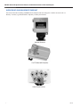
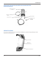
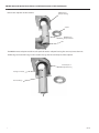
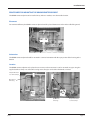
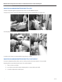
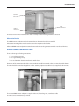
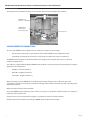
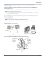
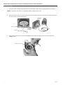
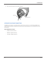
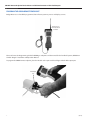
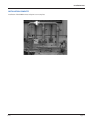
ORION® Gas Endpoints
Remote Endpoint for Gas Meters and Volume Correctors
with Pulsed Outputs
IMPORTANT:
This manual contains important information.
READ AND KEEP FOR REFERENCE.
ORI-I-61 (4-11)
62014-102 Rev. 2
Installation Data
ORION® Remote Endpoint for Gas Meters and Volume Correctors with Pulsed Outputs
Page ii
(4-11)
Installation Data
Contents
DISCLAIMER.......................................................................................................................................5
QUESTIONS OR SERVICE ASSISTANCE.............................................................................................5
PRODUCT IDENTIFICATION...............................................................................................................5
SCOPE OF MANUAL...........................................................................................................................5
PRODUCT UNPACKING AND INSPECTION........................................................................................6
LICENSE REQUIREMENTS..................................................................................................................6
IDENTIFICATION AND LABEL INFORMATION...................................................................................6
INSTALLATION TOOLS.......................................................................................................................7
Optional Materials......................................................................................................................................................... 7
OVERVIEW OF AN ORION REMOTE ENDPOINT................................................................................8
ORION REMOTE ENDPOINT FOR GAS METERS AND VOLUME CORRECTORS WITH PULSED
OUTPUTS..................................................................................................................................... 9
ENDPOINT DISASSEMBLY.................................................................................................................9
PROCEDURES FOR MOUNTING THE ORION REMOTE ENDPOINT ................................................11
Placement.......................................................................................................................................................................11
Orientation.....................................................................................................................................................................11
Location .........................................................................................................................................................................11
MOUNTING AN ORION REMOTE ENDPOINT TO A PIPE.................................................................12
MOUNTING AN ORION REMOTE ENDPOINT TO A FLAT SURFACE................................................12
Alternative Bracket........................................................................................................................................................13
WIRING CONNECTION INSTRUCTIONS...........................................................................................13
VOLUME CORRECTOR CONNECTIONS............................................................................................14
CONNECT TO A TWO-CONDUCTOR CABLE FROM A METER OUTPUT..........................................15
GAS RT CONNECTIONS....................................................................................................................15
ALTERNATIVE PULSE SOURCE CONNECTIONS...............................................................................17
PROGRAM THE ORION REMOTE ENDPOINT ..................................................................................18
INSTALLATION COMPLETE.............................................................................................................18
(4-11)
Page iii
ORION® Remote Endpoint for Gas Meters and Volume Correctors with Pulsed Outputs
Page iv
(4-11)
Installation Data
DISCLAIMER
The user/purchaser is expected to read and understand the information provided in this manual, follow any listed safety
precautions and Instructions and keep this manual with the equipment for future reference.
Misuse, mishandling and/or inadequate maintenance may impair performance and/or compromise safety.
QUESTIONS OR SERVICE ASSISTANCE
If you have questions regarding the product or this document contact:
Badger Meter, Inc.
P.O. Box 245036
Milwaukee, WI 53224-9536
Telephone: (414) 355-0400, (800) 876-3837
Fax: (888) 371-5982
On the Web: www.badgermeter.com or call your local Badger Meter representative.
PRODUCT IDENTIFICATION
Record the product identification numbers from the nameplate.
Endpoint:
Model Number ________________________________________
Serial Number _________________________________________
Tag Number ___________________________________________
This ORION remote endpoint is designed for use with gas meters and volume correctors with electric and mechanical switch
closures, also called "pulsed" outputs.
SCOPE OF MANUAL
This manual contains installation instructions for the Badger Meter ORION® and Badger Meter ORION® SE remote
endpoints for use with gas meters equipped with pulsed outputs, other instrumentation and devices with pulsed outputs,
and the gas RT (Recordall® endpoint).
Proper performance and reliability of the gas meter system depends upon installation in accordance with these instructions.
(4-11)
Page 5
ORION® Remote Endpoint for Gas Meters and Volume Correctors with Pulsed Outputs
PRODUCT UNPACKING AND INSPECTION
NOTE: If damage to the shipping container is evident upon receipt, request the carrier to be present when the
product is unpacked.
Carefully open the shipping package, follow any instructions that may be marked on the exterior. Remove all cushioning
material surrounding the product and carefully lift the product from the package.
Retain the package and all packing material for possible use in reshipment or storage.
Visually inspect the product and applicable accessories for any physical damage such as scratches, loose or broken parts, or
any other sign of damage that may have occurred during shipment.
NOTE: If damage is found, request an inspection by the carrier’s agent within 48 hours of delivery and file a claim with
the carrier.
A claim for equipment damage in transit is the sole responsibility of the purchaser.
LICENSE REQUIREMENTS
This device complies with Part 15 of FCC Rules. Operation of this device is subject to the following conditions: (1) This device
may not cause harmful interference, and (2) this device must accept any interference received, including interference that
may cause undesired operation.
No FCC license is required by a utility to operate an ORION meter reading system.
Any changes made, but not approved by Badger Meter, can void the user’s authority to operate the equipment.
CAUTION! In accordance with FCC Regulations, “Code of Federal Regulations” Title 47, Part 2, Subpart J, Section
1091, transmitters (endpoints) pass the requirements pertaining to RF radiation exposure. However, to avoid public
exposure in excess of limits for general population (uncontrolled exposure), a 12 CM distance between the
transmitter (endpoint) and the body of the user must be maintained during testing.
IDENTIFICATION AND LABEL INFORMATION
The ORION remote endpoint is packaged in a 3-1/2" x 6-1/4" gray housing that includes an external, three-conductor wire.
Certification markings are noted on the product label. Label markings include:
•
Serial number and bar code plus product description
•
FCC identification
•
Certification markings
Page 6
(4-11)
Installation Data
INSTALLATION TOOLS
•
Screwdrivers
•
Gel-Cap crimper (p/n 59983-001)
•
Coax stripper
•
Wire stripper
•
Wire-cutting pliers
•
Handheld programmer/data collector
Tools are dependent on type of mounting hardware used.
Optional Materials
You have a choice of mounting hardware or fasteners to mount the ORION remote endpoint in various meter settings.
All ORION remote endpoints are shipped from the factory unprogrammed. The field installer must connect the wires,
supplied with the ORION remote endpoint, to the pulsed output of a meter or volume corrector.
Using the handheld programmer, the installer must program ORION remote endpoint to a specific meter or
volume corrector.
(4-11)
Page 7
ORION® Remote Endpoint for Gas Meters and Volume Correctors with Pulsed Outputs
OVERVIEW OF AN ORION REMOTE ENDPOINT
This manual describes installing an ORION remote endpoint and connecting it to a volume corrector such as a
Mercury® corrector, a gas RT (Recordall® endpoint), or other pulsed device.
Volume Corrector
Gas RT (Recordall Endpoint)
Other Pulsed Devices
Page 8
(4-11)
Installation Data
ORION REMOTE ENDPOINT FOR GAS METERS AND VOLUME CORRECTORS
WITH PULSED OUTPUTS
ORION Remote Endpoint
Assembly
Clamp 3-¹/6"
diameter
Cable Strain Relief
4 Screws #8 -16 x 1"
2 Gel-Cap Connectors
1 Two-Wire
1 Three-Wire
ENDPOINT DISASSEMBLY
If necessary, the endpoint module can be removed from the ORION remote endpoint housing by holding the module
bottom and unscrewing the top nut.
Unscrew Top Nut
ORION Remote
Endpoint Housing
Hold the Module Bottom
(4-11)
Page 9
ORION® Remote Endpoint for Gas Meters and Volume Correctors with Pulsed Outputs
Remove the endpoint module and wire.
ORION Remote
Endpoint Housing
Top Nut
ORION Remote
Endpoint Module
Wire
The ORION remote endpoint module must be put back into the endpoint housing the same way it was taken out.
The flat edge and rounded "bulge" on the module must go into the rounded part of the endpoint.
Rounded part of
Endpoint Housing
Flat Edge on Module
Rounded "Bulge"
Page 10
(4-11)
Installation Data
PROCEDURES FOR MOUNTING THE ORION REMOTE ENDPOINT
The ORION remote endpoint can be installed in any indoor or outdoor, non-submersible location.
Placement
For maximum efficiency the ORION remote endpoint should be placed between 36 and 72 inches off of the ground.
36" - 72"
Orientation
The ORION remote endpoint should be mounted in a vertical orientation with the open portion of the housing at the
bottom.
Location
The ORION remote endpoint can be placed near a meter or volume corrector. It can be mounted on a pipe using the
supplied stainless clamp or to a flat surface using screws. The pipe can be either horizontal or vertical.
Endpoint Mounted
to a Horizontal Pipe
Open Portion
of Housing
Open Portion
of Housing
(4-11)
Endpoint Mounted
to a Vertical Pipe
Page 11
ORION® Remote Endpoint for Gas Meters and Volume Correctors with Pulsed Outputs
MOUNTING AN ORION REMOTE ENDPOINT TO A PIPE
Insert the clamp through the appropriate slots on the rear of the ORION endpoint.
It may be necessary to remove the endpoint from the housing to accomplish this. See pages 9-10.
The clamp fits on a pipe up to 3 inches in diameter.
A stainless steel clamp is recommended if a larger clamp is needed.
MOUNTING AN ORION REMOTE ENDPOINT TO A FLAT SURFACE
To mount a endpoint to a flat surface, such as a wall or post, four (4) screws (size #8 x 1") are provided.
Mounting holes are provided at each corner of a remote endpoint.
1. Place a screw in each hole.
2. In one lower corner of the remote endpoint place a screw and the strain relief.
3. Screw the endpoint into a wall or post.
Page 12
(4-11)
Installation Data
Screw Holes
and Screws
Cable to
Pulse Source
Cable
Strain Relief
The holes are 0.19 inches in diameter. This allows a variety of other mounting hardware to be used.
Alternative Bracket
The ORION remote endpoint can also be mounted to an alternative bracket (not supplied).
At least two mounting holes must be used to secure the endpoint to the bracket.
After the ORION remote endpoint is mounted, connect the wire to the gas meter terminals or to the gas RT wires.
WIRING CONNECTION INSTRUCTIONS
There are three types of wiring connections:
1. to a volume corrector
2. to a gas RT with gel caps
3. to an alternative electric or mechanical switch closure
Regardless of the mounting method, the remote endpoint should be mounted so the wire exits the module bottom.
The wire should be secured to the pipeline or other stationary object using cable ties (not supplied) or other means.
The remote ORION remote endpoint is supplied with a six (6) foot long cord, 3-conductor cable.
The wires can be extended to up to 75 feet.
(4-11)
Page 13
ORION® Remote Endpoint for Gas Meters and Volume Correctors with Pulsed Outputs
The endpoint wire terminations depend on the corrector device and its proximity to the endpoint.
ORION Remote
Endpoint
ORION Remote
Endpoint Wire
Connected to Meter
Volume Corrector
VOLUME CORRECTOR CONNECTIONS
To connect the ORION remote endpoint wires to a Mercury or volume corrector output:
•
Remove the protective tape or gel caps from the end of the ORION remote endpoint lead wire.
•
Depending on what type of connection is used, the wire insulation may need to be trimmed.
The ORION remote endpoint is intended to interface to any Type A pulsed output. This may be an electric or
mechanical switch closure.
The lead wires, supplied with the Badger ORION remote endpoint, connect to the pulsed output terminals using the
appropriate color-coded wires:
•
Red Wire - Positive Terminal (+)
•
Black Wire - Negative Terminal (-)
•
Green Wire - Negative Terminal (-)
When connecting a remote ORION remote endpoint to the output of the gas meter, refer to the gas meter
manufacturer's directions for the proper method of routing the cable into the electronics box and connecting to the
appropriate terminals.
Make note of the polarity of all the terminals.
The remote ORION remote endpoint uses the red wire as a positive (+) conductor and the black wire as a negative (-)
conductor of the switch closure.
The green wire is also connected to the negative (-) conductor to provide cut cable indication.
Polarity must be observed when connecting an ORION remote endpoint to the output.
Page 14
(4-11)
Installation Data
CONNECT THE ORION REMOTE ENDPOINT TO A TWO-CONDUCTOR CABLE FROM
A METER OUTPUT
If connecting a endpoint to a pair of wires, determine the proper length of wire needed from the ORION remote
endpoint and from the pulser.
1. Trim about 3/4 inch of the outer sheath from both ORION wires. This exposes the two individual wires in each.
NOTE: Do not remove the insulation from these wires.
2. Insert the two ORION remote endpoint positive (+) polarity wires into a gel cap. Make sure the two wires are
inserted fully and seated in the gel cap.
A three-wire gel cap should be used with the negative (-) polarity wire of the meter output going to the black and
green wires of the ORION unit.
GAS RT CONNECTIONS
NOTE: For detailed instructions, see the Model GAS RT Installation Data sheet
If a Badger Meter gas RT (Recordall® endpoint) is used as the source of the signal, the wires are spliced into the
gas RT.
The gas RT is installed on the index cover face.
Gas RT
Gas RT Cover
Gas RT Attached to
the Index Cover Face
Gel-caps are provided for splicing ORION remote endpoint cables to gas RT cables.
Two-Wire Gel
Cap for gas RT
Red Wire and
ORION Remote
Endpoint Red
Wire
Three-Wire Gel
Cap for gas
RT Black Wire,
ORION Remote
Endpoint
Black Wire and
ORION Remote
Endpoint Green
Wire
Strain Relief
(4-11)
Page 15
ORION® Remote Endpoint for Gas Meters and Volume Correctors with Pulsed Outputs
1. Crimp the splices carefully and completely. Use a parallel jaw crimper, such as a Badger Meter p/n 59983-001.
NOTE: For installation instructions see the Model GAS RT Installation Data sheet.
2. If the gel-cap connections are made at the gas RT unit, carefully tuck the wires and gel caps under the plastic gas
RT cover. Snap the cover back into place.
Snap Cover
Into Place
Gas RT
Gel Caps
3. If the gel-cap connections are made at the ORION remote endpoint, tuck the wires and splices up into the
ORION bottom.
Gel-Cap Connections
Page 16
(4-11)
Installation Data
4. Place a strain relief onto one corner of the endpoint.
Strain Relief
Gel-Cap Connections
ALTERNATIVE PULSE SOURCE CONNECTIONS
The ORION remote endpoint is compatible with most switch-closure pulse devices. Use the following ORION remote
endpoint polarity descriptions along with the instructions from the alternating pulse source to determine the correct
wiring scheme.
Badger ORION Remote Endpoint
(4-11)
•
Red Wire - Positive Terminal (+)
•
Black Wire - Negative Terminal (-)
•
Green Wire - Negative Terminal (-)
Page 17
ORION® Remote Endpoint for Gas Meters and Volume Correctors with Pulsed Outputs
PROGRAM THE ORION REMOTE ENDPOINT
Badger Meter uses a handheld programmer/data collector system to process and display screens.
Trimble Ranger
and IR Read Head
and Cable
Please reference the Programming Guide for ORION gas endpoints and the manual for the handheld system, ORI-IOM-52
Trimble® Ranger™ Installation and Operation Manual.
To program the ORION remote endpoint, place the IR cable so the optic read head aligns with the LED output port.
LED Output
Port
Optic Read
Head
Page 18
(4-11)
Installation Data
INSTALLATION COMPLETE
Installation of the ORION remote endpoint is now complete.
(4-11)
Page 19
ORION is a registered trademark of Badger Meter, Inc.
Other trademarks appearing in this document are the property of their respective entities.
Copyright 2011, Badger Meter, Inc. All rights reserved.
Due to continuous research, product improvements and
enhancements, Badger Meter reserves the right to change
product or system specifications without notice, except to the
extent an outstanding contractual obligation exists.
Badger Meter | P.O. Box 245036, Milwaukee, Wisconsin 53224-9536
800-876-3837 | [email protected] | www.badgermeter.com