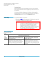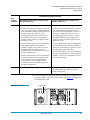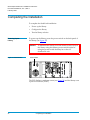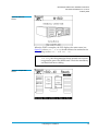
1
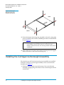
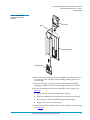
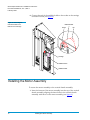
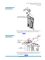
Quantum|ATL StackLink™
Installation Instructions
Introduction
3
StackLink Kit Contents .................................................................................3
Required Tools...............................................................................................4
Preparing the Rack
5
Installing the Top Mounting Tray Assembly
7
Installing the Bottom Mounting Tray Assembly
9
Installing the Carriage/counterweight Assembly
10
Installing the Motor Assembly
12
Attaching the Shuttle Assembly to the Top and Bottom Mounting Tray Assemblies
15
Installing the Libraries
16
Installing the Safety Blanking Panels
18
Document 6421009-04, Ver. 4, Rel. 0, February 2002
1
Quantum|ATL StackLink™ Installation Instructions
Document 6421009-04, Ver. 4, Rel. 0
February 2002
Cabling the Library
18
Interlibrary (Control Bus) Cabling ........................................................... 18
StackLink Motor Connection .................................................................... 19
SCSI Bus Cabling......................................................................................... 20
Power Cabling ............................................................................................. 22
Completing the Installation
24
Powering Up the Library ........................................................................... 24
Configuring the Library ............................................................................. 26
Testing the Library Robotics ..................................................................... 27
2
6207947-04fN 14
Quantum|ATL StackLink™ Installation Instructions
Document 6421009-04, Ver. 4, Rel. 0
February 2002
Introduction
0
This document explains how to install the Quantum|ATL
StackLink™. The StackLink provides the physical connection between
M1500 library modules in an M1500 stack, allowing each of the tape
drives in the stack to have access to all of the data cartridges.
Before you start the StackLink installation procedure:
StackLink Kit
Contents
0
•
Verify that the StackLink kit contains all of the necessary items (see
the following section, StackLink Kit Contents).
•
Make sure you have the necessary tools for the installation (see
Required Tools).
Table 1 lists the contents of the StackLink kit. If any items are missing,
contact Quantum|ATL.
Note:
The StackLink kit is shipped in two boxes. Before starting the
installation procedure, verify that you have received both
boxes, and that the boxes contain all of the items listed in
table 1.
Table 1 Contents,
StackLink Kit
w/ 2-high
StackLink
w/ 5-high
StackLink
w/ 10-high
StackLink
Quantity Provided
214370/01
Top mounting tray assembly
1
1
1
214380/01
Bottom mounting tray assembly
1
1
1
214390/01
Vertical shuttle assembly (2 unit)
1
N/A
N/A
214400/01
Vertical shuttle assembly (5 unit)
N/A
1
N/A
214410/01
Vertical shuttle assembly (10 unit)
N/A
N/A
1
214450/01
Shuttle motor mount assembly
1
1
1
215180/01
Carriage/counterweight
assembly
1
1
1
Part No.
Description
212579
Front safety blanking panel
N/A
3
8
212502
Rear safety blanking panel
N/A
3
8
Introduction
3
Quantum|ATL StackLink™ Installation Instructions
Document 6421009-04, Ver. 4, Rel. 0
February 2002
w/ 2-high
StackLink
w/ 5-high
StackLink
w/ 10-high
StackLink
Quantity Provided
214090/01
StackLink motor cable (.6 meter)
1
N/A
N/A
214080/01
StackLink motor cable (1 meter)
N/A
1
N/A
214070/01
StackLink motor cable (2 meter)
N/A
N/A
1
Part No.
Required Tools
4
0
Description
AS3642
Library control bus cable (.5
meter)
3
4
9
AS3643
Library control bus cable (2
meter)
N/A
2
2
6421009
Quantum|ATL StackLink™
Installation Instructions
1
1
1
YS42038
M4 x 10 socket head countersink
screw
3
3
3
YS41964
M4 x 10 cap head screw
1
1
1
YS42008
M6 caged nut
16
22
32
YS42011
M6 x 12 button head screw
16
22
32
YS40404
M6 plain washer
16
22
32
YS41964
M4 x 10 socket head cap screw
N/A
6
16
YS41952
M4 x 12 socket head cap screws
6
6
6
YS40402
M4 plain washer
6
6
6
The following tools are required to install the StackLink:
•
Flat head screwdriver (for installing caged nuts)
•
No. 2 Pozi-Driv® screwdriver
•
Metric Allen® wrenches, sizes M4 and M6
Introduction
Quantum|ATL StackLink™ Installation Instructions
Document 6421009-04, Ver. 4, Rel. 0
February 2002
Preparing the Rack
0
Before starting the StackLink installation, perform the following steps
to prepare the rack for the installation procedure:
1 Verify that the distance between the front and rear mounting strips
is between 25.5 inches and 32.25 inches (650 mm and 820 mm). If
this is not the case, adjust the mounting strips referring to the
instructions provided by the rack manufacturer.
2 Determine the correct placement of the StackLink in the rack (see
figure 1).
The top mounting tray assembly should be installed in the 1U
space just above where the uppermost library in the system will be
installed.
Note:
1U equals 1.75 inches, or 44.45 millimeters.
The bottom mounting tray should be installed as follows:
•
If you are installing a 2-high StackLink, allow 8U of space
between the top and bottom mounting tray assemblies. The
entire StackLink mechanism occupies 10U of space, 1U for the
top mounting tray assembly, 8U for libraries, and 1U for the
bottom mounting tray assembly.
•
If you are installing a 5-high StackLink, allow 20U of space
between the top and bottom mounting tray assemblies. The
entire StackLink mechanism occupies 22U of space, 1U for the
top mounting tray assembly, 20U for libraries, and 1U for the
bottom mounting tray assembly.
•
If you are installing a 10-high StackLink, allow 40U of space
between the top and bottom mounting tray assemblies. The
entire StackLink mechanism occupies 42U of space, 1U for the
top mounting tray assembly, 40U for libraries, and 1U for the
bottom mounting tray assembly.
Caution:
Take rack stability into account when determining
where to place the StackLink. If the M1500 stack will
be the only equipment in the rack, it is recommended
that you install the StackLink at the bottom of the
rack.
Preparing the Rack
5
Quantum|ATL StackLink™ Installation Instructions
Document 6421009-04, Ver. 4, Rel. 0
February 2002
3 Use a pencil to mark the correct position of the mounting tray
assemblies on the rack rails.
Figure 1 Determining the
Placement of the Mounting
Tray Assemblies
StackLink mounting position
10U of rack space
1 M1500 library module (4U)
Shelf mounting position
1U*
1 M1500 library module (4U)
Shelf mounting position
StackLink mounting position
*1U = 1.75 in (44.45 mm)
4 If the holes in the rack rails are square (untapped), insert caged
nuts (PN YS42008) into the holes where the mounting tray
assemblies will be installed (see figure 2).
6
Preparing the Rack
Quantum|ATL StackLink™ Installation Instructions
Document 6421009-04, Ver. 4, Rel. 0
February 2002
Figure 2 Inserting Caged
Nuts into the Rack Rails
Caged nuts
Flat blade
screwdriver
Installing the Top Mounting Tray Assembly
0
To install the top mounting tray assembly in the rack:
1 Remove the six screws and washers securing the rear support arms
to the sides of the top mounting tray (see figure 3).
Figure 3 Adjusting the
Depth of the Top Mounting
Tray Assembly
2 Adjust the position of the rear support arms on the top mounting
tray until the distance between the front and rear flanges is
approximately the same as the distance between the front and rear
mounting strips in the rack.
Installing the Top Mounting Tray Assembly
7
Quantum|ATL StackLink™ Installation Instructions
Document 6421009-04, Ver. 4, Rel. 0
February 2002
3 Replace the six screws and washers you removed in step 1 and
finger-tighten them. Position the front and rear screws as far apart
as the slots allow. Position the third screw approximately in the
middle slot.
Note:
Do not over-tighten the screws. You need to be able to
extend or retract the rear support arms slightly as you
install the top mounting tray assembly.
4 Position the top mounting tray assembly in the rack, referring to
figure 4 for the correct orientation.
Note:
Position the front and rear flanges on the top mounting
tray outside of the rack rails.
Figure 4 Securing the Top
Mounting Tray Assembly to
the Rack
REAR
FRONT
5 Secure the top mounting tray assembly to the rack, using eight
screws (YS42011) and washers (YS40404) provided in the StackLink
kit (see figure 4).
Note:
If the rack has widely spaced mounting holes, it may not
be possible to use all four screws to secure the rear
flanges. If this is the case, one screw per side at the rear is
acceptable.
6 Fully tighten the six screws and washers securing the rear support
arms to the sides of the top mounting tray.
8
Installing the Top Mounting Tray Assembly
Quantum|ATL StackLink™ Installation Instructions
Document 6421009-04, Ver. 4, Rel. 0
February 2002
Installing the Bottom Mounting Tray Assembly
0
To install the bottom mounting tray assembly in the rack:
1 Remove the six screws and washers securing the rear support arms
to the sides of the bottom mounting tray (see figure 5).
Figure 5 Adjusting the
Depth of the Bottom
Mounting Tray Assembly
2 Adjust the position of the rear support arms on the bottom
mounting tray until the distance between the front and rear flanges
is approximately the same as the distance between the front and
rear mounting strips in the rack.
3 Replace the six screws and washers you removed in step 1 and
finger-tighten them. Position the front and rear screws as far apart
as the slots allow. Position the third screw approximately in the
middle slot.
Note:
Do not over-tighten the screws. You need to be able to
extend or retract the rear support arms slightly as you
install the bottom mounting tray assembly.
4 Position the bottom mounting tray assembly in the rack, referring
to figure 6 for the correct orientation.
Note:
Position the front and rear flanges on the bottom
mounting tray outside of the rack rails.
Installing the Bottom Mounting Tray Assembly
9
Quantum|ATL StackLink™ Installation Instructions
Document 6421009-04, Ver. 4, Rel. 0
February 2002
Figure 6 Securing the
Bottom Mounting Tray
Assembly to the Rack
REAR
FRONT
5 Secure the bottom mounting tray assembly to the rack, using eight
screws (YS42011) and washers (YS40404) provided in the StackLink
kit (see figure 6).
Note:
If the rack has widely spaced mounting holes, it may not
be possible to use all four screws to secure the rear
flanges. If this is the case, one screw per side at the rear is
acceptable.
6 Fully tighten the six screws and washers securing the rear support
arms to the sides of the bottom mounting tray.
Installing the Carriage/counterweight Assembly
0
Now that the top and bottom mounting tray assemblies are installed,
install the carriage/counterweight assembly on the vertical shuttle
assembly (see figure 7):
1 Slide the counterweight onto the bottom of the vertical shuttle
assembly, engaging the guide wheels of the counterweight with the
vertical rails.
10
Installing the Carriage/counterweight Assembly
Quantum|ATL StackLink™ Installation Instructions
Document 6421009-04, Ver. 4, Rel. 0
February 2002
Figure 7 Installing the
Carriage/counterweight
Assembly
Carriage
Belt
Shuttle extrusion
Counterweight
2 Route the belt connecting the counterweight and carriage up and
over the top of the vertical shuttle assembly, making sure not to
twist the belt.
3 Slide the carriage onto the top of the vertical shuttle assembly,
engaging the guide wheels of the carriage with the vertical rails.
4 Secure the umbilical cable to the underside of the carriage (see
figure 8):
a
Locate the pin on the underside of the carriage.
b
Slide the umbilical cable underneath the open end of the pin.
c
Rotate the pin until the umbilical cable is held snugly.
d
Tighten the screw to secure the pin.
5 Snap the end of the umbilical chain onto the bottom of the carriage
(see figure 8).
Installing the Carriage/counterweight Assembly
11
Quantum|ATL StackLink™ Installation Instructions
Document 6421009-04, Ver. 4, Rel. 0
February 2002
6 Connect the end of the umbilical cable to the socket on the carriage
connection board (see figure 8).
Figure 8 Connecting the
Umbilical Cable to the
Bottom of the Carriage
Umbilical cable
Screw
Pin
Carriage
Umbilical chain
Umbilical cable
Installing the Motor Assembly
0
To secure the motor assembly to the vertical shuttle assembly:
1 Insert the bottom of the motor assembly into the top of the vertical
shuttle assembly, aligning the three holes in the vertical shuttle
assembly with those on the motor assembly (see figure 9).
12
Installing the Motor Assembly
Quantum|ATL StackLink™ Installation Instructions
Document 6421009-04, Ver. 4, Rel. 0
February 2002
Figure 9 Inserting the
Motor Assembly into the
Vertical Shuttle Assembly
These three holes align with
holes in the motor assembly
2 Secure the motor assembly to the vertical shuttle assembly, using
three countersink screws (YS42038) and one pan head screw
(YS41964) (see figure 10).
Countersink
screws
(YS42038)
Figure 10 Securing the
Motor Assembly to the
Vertical Shuttle Assembly
Motor assembly
Pan head
screw
(YS41964)
Vertical
rail assembly
3 Route the belt connecting the counterweight and the carriage over
the guide roller and past the motor/pulley belt retainer on the
motor assembly (see figure 11).
Installing the Motor Assembly
13
Quantum|ATL StackLink™ Installation Instructions
Document 6421009-04, Ver. 4, Rel. 0
February 2002
Figure 11 Routing the Belt
4 Connect the ribbon cable from the vertical shuttle assembly to the
socket on the control board at the rear of the motor assembly as
shown in figure 12:
a
Route the ribbon cable behind the motor plate.
b
Insert the ribbon cable connector through the rectangular hole
at the top of the motor plate.
c
Connect the ribbon cable connector to the socket on the control
board.
Figure 12 Connecting the
Ribbon Cable
Rectangular hole
Motor plate
Ribbon cable
14
Installing the Motor Assembly
Quantum|ATL StackLink™ Installation Instructions
Document 6421009-04, Ver. 4, Rel. 0
February 2002
Attaching the Shuttle Assembly to the Top and Bottom
Mounting Tray Assemblies
0
To attach the shuttle assembly to the top and bottom mounting tray
assemblies:
1 At the rear of the rack, lift the shuttle assembly and position it so
the carriage faces forward into the rack.
2 Rest the lower end of the shuttle assembly on top of the bottom
mounting tray assembly.
3 Ensure that the motor at the top of the shuttle assembly is aligned
with the cutout in the top mounting tray assembly.
4 Slide the shuttle assembly fully into the rack.
5 Secure the shuttle assembly to the upper and lower mounting trays
using six screws (YS41952) and washers (YS40402) provided in the
StackLink kit (see figure 13).
Note:
Figure 13 Installing the
Shuttle Assembly
Tighten these screw to finger-tightness only. You will
finish securing the StackLink after you have installed
libraries in the rack.
(SHOWN OUTSIDE OF RACK)
FRONT
REAR
Attaching the Shuttle Assembly to the Top and Bottom Mounting Tray Assemblies
15
Quantum|ATL StackLink™ Installation Instructions
Document 6421009-04, Ver. 4, Rel. 0
February 2002
Installing the Libraries
0
Now that the StackLink is installed in the rack, install the libraries as
follows:
1 If you have not done so already:
Unpack and install the rack mount shelves on which the M1500
libraries will be placed, referring to the Quantum|ATL M1500
Universal Rack Mount Kit Installation Instructions (PN 6421004).
a
Note:
b
The libraries will be installed from the top of the rack
downward; position the rack mount shelves accordingly.
For example, if you were installing two libraries in a
5-high StackLink, you would install two sets of rack
mount shelves: one set 4U below the StackLink top
mounting tray assembly, and another set 8U below the
StackLink top mounting tray assembly.
Unpack the M1500 libraries, referring to the Quantum|ATL
M1500 Library Unpacking Instructions (PN 6421002).
Caution:
Make sure to remove the StackLink cover plate from
the rear of the libraries.
2 Install an M1500 library in the top StackLink position.
a
Verify that the rack mount shelves are level and securely
fastened to the rack.
b
With the help of another person, lift the library onto the rack
mount shelves.
Caution:
16
When sliding the library into the rack, be very careful
not to abrade or disconnect the ribbon cable that
connects the vertical shuttle assembly to the control
board on the motor assembly. See figure 12 for the
location of this cable.
c
Slide the library all the way into the rack.
d
Press the white button next to the left magazine access door
and open the door.
Installing the Libraries
Quantum|ATL StackLink™ Installation Instructions
Document 6421009-04, Ver. 4, Rel. 0
February 2002
Notice the hole behind the magazine access door, at the lower
edge of the library (see figure 14).
e
This hole provides access to the rack mount clamp screw.
Figure 14 Securing the
Library to the Rack
Access hole
for rack mount
clamp screw
Insert a no. 2 Pozi-Driv screwdriver into the hole and turn the
rack mount clamp screw clockwise to tighten it fully.
f
Caution:
Do not over-tighten this screw. When the screw
begins to tighten, turn it another 1/4 turn clockwise
and then stop.
As you tighten this screw, a lever protrudes from the side of the
library and presses against the rear side of the rack rail.
g
Repeat steps 2d through 2f to secure the right side of the library
to the rack.
h
Close the magazine access doors.
3 Repeat steps 2a through 2h to install additional M1500 library
modules below the first one.
Note:
Install the libraries from the top of the StackLink
downward, leaving no space between the libraries. The
cable lengths are designed for libraries installed
immediately adjacent to one another.
4 Once all the libraries are installed, fully tighten the StackLink
vertical shuttle assembly (see figure 13).
Installing the Libraries
17
Quantum|ATL StackLink™ Installation Instructions
Document 6421009-04, Ver. 4, Rel. 0
February 2002
Installing the Safety Blanking Panels
0
To avoid personal injury or damage to the StackLink mechanism,
install safety blanking panels over all empty locations in the M1500
stack.
1 If the holes in the rack rails are square (untapped), insert caged
nuts into the holes where the front safety blanking panels will be
installed.
2 Install front safety blanking panels (212579) at the front of the rack,
securing each panel with two screws (YS42011) and washers
(YS40404).
3 Install rear safety blanking panels (212502) at the rear of the rack,
securing each panel with two screws (YS41964).
Cabling the Library
0
The library cabling procedure consists of the following steps:
Interlibrary (Control
Bus) Cabling
0
•
Interlibrary (control bus) cabling
•
StackLink motor connection
•
SCSI bus cabling
•
Power cabling
The intelligent control bus allows the individual libraries in the rack to
communicate. To connect this bus:
1 Connect the top M1500 module in the rack to the terminator on the
front of the motor assembly, using one of the library control bus
cables provided (PN AS3642).
2 Daisy chain the control bus as shown in figure 15, using the library
control bus cables provided (PN AS3642).
18
Installing the Safety Blanking Panels
Quantum|ATL StackLink™ Installation Instructions
Document 6421009-04, Ver. 4, Rel. 0
February 2002
Library control bus terminator
Figure 15 Library Control
and StackLink Power
Cabling
Library control
bus (daisy
chained)
This cable
completes a loop
back to the I2C
terminator board
3 Connect the bottom M1500 module in the rack to the I2C
terminator board:
StackLink Motor
Connection
0
•
On a 2-high stack, use library control bus cable PN AS3642.
•
On a 5-high or 10-high stack, use library control bus cable
PN AS3643.
Once you have completed the interlibrary cabling, connect the
StackLink motor cable (PN 214090/01, 214080/01, or 214070/01) from
the StackLink motor to the StackLink motor drive on any of the library
modules (see figure 16).
Note:
The library module that is connected to the StackLink motor
becomes the GUI master.
Cabling the Library
19
Quantum|ATL StackLink™ Installation Instructions
Document 6421009-04, Ver. 4, Rel. 0
February 2002
StackLink motor
Figure 16 StackLink Motor
Connection
StackLink motor
drive
(Interlibrary cables
omitted for clarity)
SCSI Bus Cabling
0
Install the SCSI cabling, referring to figure 17 and the SCSI and
termination guidelines on page 21.
Note:
20
Notice that the host computer is connected to the robotics
connector on only one of the M1500 library modules. This
library module is called the SCSI master.
Cabling the Library
Quantum|ATL StackLink™ Installation Instructions
Document 6421009-04, Ver. 4, Rel. 0
February 2002
(Interlibrary and
StackLink motor
cables omitted for
clarity)
Figure 17 Typical SCSI
Bus Connections
To host adapter
(may be connected
to any M1500
module)
Remaining library
connectors may
be left
unterminated
To host adapter(s)
The number of drives per bus is determined by the
data transfer performance of the host and drives.
0
SCSI Cabling Guidelines
Refer to these SCSI cabling guidelines when completing the SCSI
cabling:
•
Each device on the SCSI bus must have a unique SCSI ID. The
default settings are: library robotics = 0, tape drive 1 = 1, tape drive
2 =2. You can change these SCSI ID settings using the Drive ID and
Library ID options on the GUI Configuration screen.
•
Termination must be provided at each end of the SCSI bus (see
Terminator Power).
•
Do not mix low voltage differential (LVD) and high voltage
differential (HVD) SCSI devices on the same bus. Ensure that the
host adapters match the devices on the bus.
•
All SCSI cables must be shielded or double shielded to meet EMI
specifications.
•
The maximum total SCSI bus length for an LVD SCSI bus is 40 feet
(12 meters).
•
The maximum total SCSI bus length for an HVD SCSI bus is 82 feet
(25 meters).
Cabling the Library
21
Quantum|ATL StackLink™ Installation Instructions
Document 6421009-04, Ver. 4, Rel. 0
February 2002
0
Terminator Power
External terminators must be installed at the end of each SCSI bus.
Power for the terminator must be supplied by at least one device on
the SCSI bus.
In the factory default configuration, the library robotics supplies
terminator power. You can turn this terminator power off using the
Terminator Power option on the GUI Configuration screen.
Power Cabling
0
To connect the library to AC power:
1 Referring to table 2, select appropriate AC distribution unit(s) for
your library configuration and input voltage.
Warning:
AC distribution units (power strips) must be certified
for safety by an agency acceptable to the country of
use. For use in the United States and Canada,
distribution units must be UL listed and CSA
certified. For use in Europe, distribution units must
be CE marked. National certifications for other
countries depend on local requirements.
Table 2 AC Distribution
Unit Requirements, 200V
to 240V
Distribution Unit Requirements
# of
Library
Modules
1-5
22
200-240V 50-60Hz supply voltage (Europe
& international, etc.)
100-120V 50-60Hz supply voltage (USA,
Canada, Japan, etc.)
Connect libraries to one AC distribution unit
rated minimum 10A, minimum 1.00mm2
<HAR> cord with minimum 10A plug. Must
be 3 wire grounding plug and wall outlet.
Connect libraries to one UL Listed AC
distribution unit rated 15A or 20A, with a
minimum 14AWG 3 wire cord, and a 15A or
20A plug. Must be 3 wire grounding plug and
wall outlet.
Cabling the Library
Quantum|ATL StackLink™ Installation Instructions
Document 6421009-04, Ver. 4, Rel. 0
February 2002
Distribution Unit Requirements
# of
Library
Modules
6-9
200-240V 50-60Hz supply voltage (Europe
& international, etc.)
100-120V 50-60Hz supply voltage (USA,
Canada, Japan, etc.)
Select one of the following options:
Select one of the following options:
• Connect no more than 5 libraries to each of
two AC distribution units rated minimum
10A, minimum 1.00mm2 <HAR> cord with
minimum 10A plug. Must be 3 wire
grounding plug and wall outlet. The AC
distribution units must be plugged into
separate outlets served by separate circuit
breakers or fuses.
• Connect no more than 5 libraries to each of
two AC distribution units rated 15A or
20A, with a minimum 14AWG 3 wire cord,
and a 15A or 20A plug. Must be 3 wire
grounding plug and wall outlet. The AC
distribution units must be plugged into
separate outlets served by separate circuit
breakers or fuses.
• Connect all libraries to one AC distribution
unit rated minimum 10A, minimum
1.00mm2 <HAR> 3 wire cord with 3 wire
IEC60309 rated 16A. Must be 3 wire
grounding plug and wall outlet and have a
ground warning label.
• Connect all libraries to one AC distribution
unit rated 20A, with a minimum 14AWG 3
wire cord, with a 20A plug. Must be 3 wire
grounding plug and wall outlet.
• Connect all libraries to one AC distribution
unit rated minimum 10A, minimum 1.00
mm2 <HAR> 3 wire cord permanently
wired to the electrical supply. Must be
connected with a 3 wire cable and have a
ground warning label.
10
Same requirements as 6-9 above.
• Connect all libraries to one AC distribution
unit rated minimum 20A, with a minimum
14AWG 3 wire cord, permanently wired to
the electrical supply.
Same requirements as 6-9 above, but the AC
power distribution unit must also have a
ground warning label.
2 Connect the power cable (provided in the library accessories kit) to
the power inlet on the back of the library (see figure 18) and to the
AC distribution unit.
Figure 18 Power Inlet
Power inlet
Cabling the Library
23
Quantum|ATL StackLink™ Installation Instructions
Document 6421009-04, Ver. 4, Rel. 0
February 2002
Completing the Installation
0
To complete the StackLink installation:
Powering Up the
Library
0
•
Power up the library
•
Configure the library
•
Test the library robotics
To power up the library, press the power switch on the back panel of
the library (see figure 19).
Caution:
Figure 19 Power Switch
To minimize the effects of inrush current, always turn on
the library using this library power switch instead of
using the power switch that may be on the AC
distribution unit.
Power switch
The GUI displays a welcome screen (see figure 20) and the library runs
a power-on self-test (POST).
24
Completing the Installation
Quantum|ATL StackLink™ Installation Instructions
Document 6421009-04, Ver. 4, Rel. 0
February 2002
Figure 20 Welcome
Screen
When the POST is complete, the GUI displays the main screen (see
figure 21), where 1500 - x0 Ready should indicate the maximum size
of the library, such as 1500 - 40 or 1500 - 100.
Note:
If any of the library module main screens indicates
1500 Ready, then that particular library module has not been
recognized as part of the M1500 stack. Check the interlibrary
and StackLink motor cabling.
Figure 21 Sample Main
Screen
Completing the Installation
25
Quantum|ATL StackLink™ Installation Instructions
Document 6421009-04, Ver. 4, Rel. 0
February 2002
Configuring the
Library
0
Library configuration works somewhat differently in an M1500 stack
than it does in a single library module.
Note:
The library must be power cycled before any configuration
changes will take effect.
SCSI Import/Export Elements
0
To configure SCSI import/export elements using the Import/Export
option, you must use the GUI on the GUI master. See the
Quantum|ATL M1500 Library User’s Guide (PN 6421000) for more
information about this option.
Note:
The GUI master is the library module that is connected to the
StackLink motor (see figure 16 on page 20).
Caution:
Although the Import/Export option appears on the GUIs
of all of the library modules, it is only functional on the
GUI master.
Tape Drive SCSI IDs
0
To set tape drive SCSI IDs, use the GUI on the library module that
contains the tape drives you wish to affect. For example, the addresses
of tape drives installed in library level 2 should be set from the GUI on
library level 2.
Library SCSI Settings
The SCSI host can be connected to any of the library modules. The
SCSI settings for the M1500 stack (SCSI ID, emulation mode, etc.) are
determined by the settings of the library module that is connected to
the host (the SCSI master).
If you change the SCSI settings from the defaults, it is recommended
that you change all library modules to the same settings.
26
Completing the Installation
0
Quantum|ATL StackLink™ Installation Instructions
Document 6421009-04, Ver. 4, Rel. 0
February 2002
Testing the Library
Robotics
0
To complete the installation, run the Demo 5 program to verify that the
StackLink robotics are working correctly:
1 Select a library module on which to initiate the test.
2 Load a single data cartridge into the left magazine of the selected
M1500 module.
Leave all other slots in the M1500 stack empty.
3 On the GUI main screen of the selected M1500 module, press Menu.
The GUI displays the Menu screen (see figure 22).
Figure 22 Menu Screen
4 Press Demo.
The GUI displays the Demo Programs screen (see figure 23).
Figure 23 Demo Programs
Screen
Completing the Installation
27
Quantum|ATL StackLink™ Installation Instructions
Document 6421009-04, Ver. 4, Rel. 0
February 2002
5 Press the Up or Down buttons to select Demo 5.
6 Press Select.
The Demo 5 program starts. The program moves the data cartridge
randomly between levels until you stop the program. It is
recommended that you allow the program to run for five times the
number of levels in the library; for example, a ten level stack
should be run for at least 50 cycles.
7 Ensure that all levels are accessed by observing the cartridges
moving from level to level. If not, re-check the interlibrary cabling.
8 When the program has run successfully for the recommended
number of cycles, press Stop to end the program.
The GUI stops when the current cycle is completed.
The StackLink installation is now complete.
28
Completing the Installation