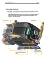
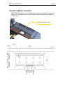
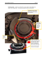
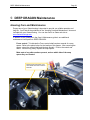
1
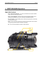
DEEP DRAGON Setup, Use, and Care Guide Introducing DEEP DRAGON Copyright 2014, Gates Underwater Products, Inc. Last document revision: January 15th, 2014 Photos by Lee Peterson / Marine Camera Distributors and John Ellerbrock This manual and current revision is available in 8.5 x 11 size and full color at http://www.gateshousings.com/documentation.html Gates Underwater Products, Inc. 13685 Stowe Drive Poway, California 92064 USA Phone: Fax: Web: 800.875.1052 toll-free in the U.S. 858.391.0052 outside the U.S. 858.391.0053 GatesHousings.com Page 2 Introducing DEEP DRAGON Table of Contents Setup, Use, and Care Guide .............................................. 1 1: Introducing DEEP DRAGON ............................................. 5 Features ............................................................................. 5 Warranty Disclaimer .......................................................... 5 Unpacking DEEP DRAGON .............................................. 6 2: Cautions............................................................................. 7 3: DEEP DRAGON Setup ...................................................... 9 DEEP DRAGON Housing Preparation .............................. 9 Epic Camera Preparation ................................................ 13 Camera / Lens Installation ............................................... 16 Lens Gear Drives (LGD’s) ............................................... 21 REDMOTE Controller Installation .................................... 24 External Monitors ............................................................. 26 Audio Connections (Optional) .......................................... 31 Video Connections (Optional) .......................................... 32 Water Alarm (Optional) .................................................... 33 Check Operation .............................................................. 34 Port and Port Extender .................................................... 35 Housing Closure .............................................................. 36 Seal Check ...................................................................... 38 Final Checks .................................................................... 39 4: DEEP DRAGON Operation ............................................. 40 Right Side Controls .......................................................... 40 Left Side Controls ............................................................ 41 Rear Controls ................................................................... 42 Monitor Controls .............................................................. 43 Buoyancy Adjustment ...................................................... 44 Adjustable Handles .......................................................... 47 Port Options ..................................................................... 48 Tripod Mount (Optional) ................................................... 49 Tripod Legs (Optional) ..................................................... 50 Accessory Mount Locations ............................................. 51 Lighting Systems ............................................................. 52 Controlling Reflections ..................................................... 52 Using the Optitek ProLock Nikon Mount .......................... 53 Travel / Transport ............................................................ 55 5: DEEP DRAGON Maintenance ......................................... 56 Housing Care and Maintenance ...................................... 56 O-Ring Care and Maintenance ........................................ 57 6: Customer Support ............................................................ 58 Page 3 Introducing DEEP DRAGON This page intentionally left blank Page 4 Introducing DEEP DRAGON Page 5 1: Introducing DEEP DRAGON Congratulations on owning a new Gates product: the DEEP DRAGON housing. You’ve selected a product that will provide years of value and reliable service. We designed DEEP DRAGON specifically for the RDC EPIC-DRAGON, EPIC-X, EPIC-M (‘Epic’ camera for short) and Scarlet digital cinema cameras. Please read through this entire guide to learn about DEEP DRAGON so you can get the most out of this imaging tool. In this section, we’ll introduce you to the features of DEEP DRAGON so you can get started. Features DEEP DRAGON has several key features: Lens flexibility. DEEP DRAGON can accommodate a variety of different cinema and DSLR lenses with no change to control locations. Focus, Iris, Zoom and Rec/Stdby remain in the same location regardless of optics used. Full control access. All controls are accessible on DEEP DRAGON, including the REDMOTE™. Cinema-grade design. Lens choice and control access are just two of the many features designed into DEEP DRAGON. A/R coated glass optics, tally light, HDSDI surface feed, comm. inputs and Seal Check are a few of the items any professional will appreciate. Warranty Disclaimer DEEP DRAGON is a tool that, like any tool, requires knowledge and understanding to be effective. Your responsibility is to learn the proper setup, use and care of DEEP DRAGON. Because we can only provide you with the information necessary to do so, Gates does not warrant the contents of your housing (e.g. your camera and lenses) under any circumstance. We warrant DEEP DRAGON as an image acquisition tool for a period of 2 years. The Seal Check unit is warranted for 1 year. Optics (Dome and Flat ports) are warranted for a period of 1 year or 100 hours salt water contact, whichever comes first. Gates does not warrant optical performance or image quality. If you have any questions about the setup, use and care of DEEP DRAGON, contact Gates directly. Details are in section 6. Introducing DEEP DRAGON Page 6 Unpacking DEEP DRAGON After you remove DEEP DRAGON from its shipping container, carefully inspect it for missing parts or damage that may have occurred during shipment. If you discover any discrepancies, contact Gates or your dealer immediately for assistance. Standard Parts DEEP DRAGON Housing Tool Kit with case Camera Mount Lens Gear Drives (2x upper and 1x lower) Various assembly and spare parts for DEEP DRAGON including bolts, set screws and o-rings. Monitor Shell Spare O-Ring Kit * 5.6” LCD Monitor Shell or Carry Handle * 5” RED PRO Monitor Shell Trim Weights (quantity dependent on configuration) Hard Sided Rolling Case x 2 Seal Check system Optional Parts * = necessary for operation Port Extender(s) of choice for your lens* Port(s) of choice (Dome, either glass or acrylic, or Flat) and shade* Port Mask (as applicable for specific lenses) Focus / Iris Indicator Rings Guide Bars and acetyl drive shafts for your lens of choice* Microphone or Hydrophone Water alarm HD-SDI surface feed bulkhead connector and cable Light System Cautions Page 7 2: Cautions SEAL CHECK VACUUM must remain below 6 in Hg. More vacuum can inhibit the transfer of heat away from the housing. Keep the vacuum on DEEP DRAGON below 6 in Hg. Camera Fan. Set the Epic camera fan to ‘Adaptive’. SETTINGS SETUP SYSTEM FAN CONTROL. This setting allows the EPIC camera to maintain a calibrated sensor temperature for optimal image quality. Refer to page 74 in the DSMC Operations Guide (Revision F). Do not block any ventilation openings or obstruct cooling fan airflow. The intake is in the front just below the lens and the exhaust is on the top of the camera. Set to ‘ADAPTIVE’ Cautions Page 8 LEMO CONNECTOR MATING. When mating LEMO connectors, ensure alignment of the red dots on the plug and receptacle before engagement. It is the user’s responsibility to verify alignment, proper connection, and connector integrity. Ensure alignment before engaging any LEMO connector. Also ensure the SYNC and CTRL connectors are mated properly to the SYNC and CTRL locations on the EPIC / Scarlet cameras. TRANSPORT. NEVER ship or transport your Epic cameras inside the DEEP DRAGON housing. The housing was not designed for this purpose and severe damage may result. USER RESPONSIBILITY. This Setup, Use and Care guide contains important detailed procedures for setup and use of DEEP DRAGON. It is the user’s responsibility to read, understand and employ these procedures. Failure to do so can result in poor or non-operation of DEEP DRAGON and may void your warranty. Contact Gates if you have questions this manual or using DEEP DRAGON. REPLACE FAN. RED Digital Cinema has issued a warning on page 33 of the Epic camera user guide. If you have a camera that requires fan replacement, you must do so prior to operating the Epic camera in DEEP DRAGON housing. Failure to follow this instruction may result in camera damage. DEEP DRAGON Setup Page 9 3: DEEP DRAGON Setup DEEP DRAGON requires complete and thorough setup prior to use. DEEP DRAGON Housing Preparation Port. Remove the Port by rotating 90 degrees either direction. Gently pull the Port away from the Port Extender. TIP: Liberal lubrication of the Port o-ring allows easy rotation during installation/removal. Port Extender. Remove the Port Extender by removing 4 screws around the perimeter. Rotate the port 90 degrees either direction, then gently pull forward to remove. Note: DEEP RED shown Remove 4 screws securing the port extender and remove. Pull the Port Extender forward until it clears the gear drive mechanisms. Note: DEEP RED shown DEEP DRAGON Setup Page 10 Shell removal. Before releasing the 3 latches on the shell, retract the Zoom, Iris and Power control on the right side, and the Assignable control on the left (see the controls section for additional details). Release the latches by depressing the lock and pulling up on the latch. Once released the shell will slide to the rear on the foot rails until free. Step 3. Slide the shell back until free from the housing. Note: If you are opening the shell after a dive, secure the monitor to the top of the front shell or set off to the side of the housing. Note: DEEP RED shown DEEP DRAGON Setup Page 11 Unwrap Connectors. Several connectors are bundled together for travel and protection. Remove the protective covering and separate the cables. Unbundle the connectors from the protective covering. Save the covering for later travel use. DEEP DRAGON Setup Page 12 Camera Tray Removal. Lay the SYNC, CTRL, Power, and other connectors that may be optionally installed to the side, away from camera installation Loosen 3 thumbscrews and slide the camera mount to the rear and free of the housing. Camera Mount removed from DEEP DRAGON. Loosen three thumbscrews and slide the camera tray to the rear, and free of the housing. DEEP DRAGON Setup Page 13 Epic Camera Preparation Camera Settings. Prior to preparing the camera for setup, check the following settings are made. Firmware version shown is 4.0.1. Note that other firmware releases may be different. GPIO. The SYNC and CTRL ports must be set for proper interface to DEEP EPIC. At this writing for the current firmware release, the ports are set as follows: Sync Mode: SETTINGS SETUP GPIO/SYNC SYNC Set Sensor Sync mode to ‘Off” Set Sensor Sync Mode to Off Brain GPIO: SETTINGS SETUP GPIO/SYNC BRAIN GPIO Set Camera Input, Brain GPI in High, Brain GPI in Low and Camera Output to the setting shown. Set Camera Setting here are shown DEEP DRAGON Setup Page 14 USER KEY / KEY ACTION. SETTINGS SETUP KEYS ADVANCED Set Key Source, User Key and Key Action as shown. Set Camera Setting here are shown PRE-RECORD If you plan to use the Pre-Record feature, note that this feature is a two step process. Pre-Record must first be mapped to a user key (e.g. User 1 or @ on the SSD module, or on the Redmote), and then initiated prior to activating Record (via housing Record Trigger or otherwise). Refer to the Epic Camera Operations Guide for more details on mapping features like Pre-Record to a User Key. DEEP DRAGON Setup Page 15 Fan. Set EPIC camera fan to ADAPTIVE for most efficient cooling. Settings are Set to ADAPTIVE Do not block any ventilation openings or obstruct cooling fan airflow The intake is in the front just below the lens, and the exhaust on the top of the camera. Camera Basics Strip down your EPIC to the camera body only. Remove all accessories, battery/drive and lens and other accessories. Remove all accessories and lenses from EPIC or Scarlet. DEEP DRAGON Setup Page 16 Camera / Lens Installation Camera Mount Installation. The Camera Mount is secured to the EPIC camera by two mounting screws on the bottom. Locate the two screws to the mating 3/8-16 threaded holes on the camera. Thread by finger tight first, then finish with a coin or wide-bladed screwdriver. Tighten firmly. Secure EPIC to Camera Mount with two mounting screws. Tighten firmly. Plug in the power cable to the camera. Plug in the Power cable. Remove the connector caps and plug in the power cable to the EPIC camera. Place camera to housing. Place the Camera / Camera Mount assembly onto the Place the Camera / Camera Mount assembly in the housing. DEEP DRAGON Setup Page 17 Camera Tray as shown in the photo. Connect External LCD. Slide the assembly forward until 2 in / 5 cm from fully seating into the housing. This is a good point to connect the LCD cable on the front of the EPIC camera. See the subsequent sections on installing the RED 5.6 in or RED PRO 5 in external monitor shells to the housing. Slide the EPIC camera forward and plug in the LCD Connector. Top View of LCD Connector. DEEP DRAGON Setup Page 18 Plug in the optional Submersible Mic, Hydrophone, or Comm input to Mic-1 or Mic-2 locations on the EPIC camera. Place the audio connections. AUDIO CONNECTIONS. Failure to connect the Audio connectors may interfere with the camera fan, and overheating will result. Fully insert and secure the camera. Slide the assembly forward until it stops firmly under the thumbscrews. If there is obstruction, inspect for the reason. A thumbscrew or cable are likely the obstruction. Tighten thumbscrews. Three thumbscrews secure the EPIC camera to the housing. Tighten by hand, and if desired use the 3/16 hex tool to tighten firmly (this is usually not necessary). SYNC / CTRL Connections. Plug in the SYNC and CTRL connectors to the corresponding ports on the camera. These are clearly marked as shown in the photos. CAUTION: SYNC / CTRL CONNECTIONS. Failure to properly connect the SYNC / CTRL connections may damage your EPIC / Scarlet camera. Other Connections. Plug in HD-SDI (optional) if installed. DEEP DRAGON Setup Page 19 Slide the EPIC camera fully forward until it stops and the camera mount is visually aligned with the camera mounts. Secure the camera with three thumbscrews. Tighten firmly with the 3/16 ball drive or 3/16 stub length hex key tools. Tilt the housing forward and plug in the SYNC and CTRL Connections. The connectors are clearly marked. Plug in the optional HD-SDI connector if installed. DEEP DRAGON Setup Page 20 Power Connector. Plug in the power connector on the side of the V-Lock battery mount as shown. Install a charged REDBRICK battery. The red LED just above the EPIC camera record button will verify power is available to the camera. At this time, the following batteries are reported by customers to fit in DEEP EPIC: ·IDX E10 · IDX E10S · IDX E9 · Hawkwood V90 Install the Power connector here, on the side of the VLock battery mount. Install a charged battery Mount lens. Mount the lens you plan to use at this time. Mount the lens to the EPIC camera. DEEP DRAGON Setup Lens Gear Drives (LGD’s) General Notes. This section addresses the installation of three LGD’s – 2 x CCW (CounterClock Wise) and 1 x CW (Clock Wise). These designators are applied because two LGD’s point in a CCW direction and the other in a CW direction, The LGD’s are marked CCW and CW. Page 21 DEEP DRAGON includes three LGD’s – 2x CCW and 1x CW. You will install guide bars and drive shafts that match the lens of your choice. A lens cross reference is included in your DEEP DRAGON documentation package and is updated on a regular basis. Visit GatesHousings.com or contact Gates for a current cross reference. Secure Guide Bars. Insert the guide bars by threading them into the front bulkhead. Tighten firmly by hand – no tools are required but wrench flats are provided on the guide bars should this be necessary. Install Drive Shafts. These are ¼” black delrin and have a flat spot milled into one end. This end inserts into the drive coupler at the face of the front bulkhead. Secure gently with the set screw on the coupler. Do not overtighten. Insert the drive shaft into the coupler. One end of the shaft will have a small flat spot. Align this with the set screw, and tighten gently. Do not overtighten. Note: DEEP RED shown Thread the Guide Bar into the front shell and tighten by hand. DEEP DRAGON Setup Page 22 LGD’s mounting. Install the LGD’s in their proper orientation with pivot gear screws facing forward. Slide it onto the guide bar and drive shaft, then line up the LGD with the lens gear you wish it to access. The sequence of tightening screws on the LGD’s is important. Step 1. Tighten the LGD mount screw securing it to the guide bar. Critical: the drive shaft/gear hub must be centered with the opening on the bracket. Center the drive shaft/gear hub to the bracket. Tighten the screw and secure the LGD to the guide bar. Step 2. Pivot the larger gear onto the lens gear such that it makes intimate contact. Carefully observe that the gear is still properly aligned and the drive shaft/gear hub is centered with the LGD bracket (see photo). Tighten the two pivot screws gently to secure it in position. With the drive shaft/hub centered, pivot the larger gear to make intimate contact with the lens gear. Gently tighten 2 pivot screws. Step 3. Firmly tighten the screw that couples the drive gear hub to the drive shaft. TIP. The gear hub / drive shaft coupling acts like a clutch – the drive shaft will ‘slip’ when reaching the end of travel in either direction. Greater tightening the screw will allow less slip. Adjust this amount of slip at your discretion. Insert the Power connector here, on the side of the V-Lock battery mount. DEEP DRAGON Setup Page 23 Set the focus/iris indicators. The left side Focus control and right side Iris control have focus and iris dials. These shipped in the parts kit. These may be aluminum and pre-marked for the lens, or white plastic for marking focus / iris indications yourself. Rotate the focus or iris knob to either end of the lens travel, then position the indicator ring to that setting aligned with the marker pin on the housing. Secure the ring with the two set screws in the knob to retain. The indicator rings now display lens settings on the knob during use. Rotate the gear to either end of travel, set the ring to the matching setting, then secure with two set screws. Verify Operation. Once positioned and secured check operation of the Focus and Iris controls. They should rotate freely – but with slight resistance – in both directions and through the entire range of travel. If not, repeat steps 1-3. In a subsequent section “Check Operation” you will power on the camera and verify the Zoom control is also smooth and operational. DEEP DRAGON Setup Page 24 REDMOTE Controller Installation The RDCC REDmote™ is installed in the rear shell of DEEP DRAGON. The following photos show the REDMOTE Controller as separated from the housing. This is for illustration purposes only – do not remove the entire REDMOTE Controller from the housing. Remove REDMOTE Cradle. The REDMOTE Cradle is secured only by magnets. Pull the cradle away from the REDMOTE Controller to separate. REDMOTE Controller Parts: REDMOTE Controller Panel (shown removed from the housing REDMOTE Cradle; Mount Screw; RDCC REDmote™ (not included) Install REDmote™. Insert the REDmote™ at an angle as shown in the photo. It will fully seat into the cradle. Secure with the small thumbscrew. Insert the REDmote™ into the Cradle at an angle. REDmote™ will ‘snap’ into place when fully seated. Secure with thumbscrew. DEEP DRAGON Setup Page 25 Mate REDMOTE Cradle to REDMOTE Controller. When the REDMOTE Cradle is near the REDMOTE Controller, the magnets will self align and guide the Cradle into position. It will ‘snap’ when seated. Be sure to position the Power control to the ‘LOCK’ position to clear the cradle when mating. Position the power control to the ‘LOCK’ position for mating. The REDMOTE Panel will mate to the Cradle when bought in proximity to each other. The magnetic fasteners will self-align and secure them together. The REDMOTE Controller fully assembled. Reminder: this assembly is shown outside the housing for illustration purposes only. Do not remove the REDMOTE Controller from the housing. DEEP DRAGON Setup Page 26 External Monitors Two monitor options are available for use with DEEP DRAGON: the RED 5.6 in and RED PRO 5 in. RED 5.6 in External Monitor Open the case. Remove the 4 screws that secure the back to the monitor shell. Remove 4 screws to open the LCD Monitor shell. Plug in the LCD cable, then insert the LCD into the shell. Lead with the edge closest to the wire first. Clean the window / LCD. If necessary, clean the inside of the window and blow out any foreign matter. Clean the LCD screen as well. Connector. Plug in the LCD connector. Be sure it is fully seated to the LCD. Install the LCD. The RED LCD will insert face down (against the window) with the connector facing the rear. Insert the left edge first (closest to the wire). It should rest inside the shell without obstruction. Inspect the o-ring. As always, inspect the o-ring for foreign matter. Wipe your finger around the silicone o-ring to clear away any dirt, hair, etc. DO NOT LUBRICATE the silicone o-ring. Inspect the o-ring. Wipe clean with your finger to remove foreign material. DO NOT lubricate orange o-rings. DEEP DRAGON Setup Page 27 Close the monitor shell. Mate the rear shell to the housing. Insert and tighten the 4 screws until snug. Tighten until there is no visible gap between shells. A good indicator is when the orange o-ring is no longer visible. Close the shell and secure with 4 screws. Tighten firmly, but do not overtighten. Plug in the external monitor to the camera. The LEMO connection to the camera is accomplished by passing the connector through the bulkhead opening on the right side of the front shell. Pass the connector through then tighten the bulkhead connection. Lastly, plug the connector into the camera LCD port. See the section above “Camera / Lens Installation” for detail on connecting to the EPIC camera. Pass the right angle connector through the bulkhead opening. DEEP DRAGON Setup Pass the cable through up to the mating collar. Page 28 Face the right angle LEMO connector to the rear, then tighten the collar until it stops. DEEP DRAGON Setup Page 29 RED PRO 5 in External Monitor Open the case. Remove the 3 screws that secure the back to the monitor shell. Remove 3 screws to open the LCD Monitor shell. Insert the RED PRO monitor at an angle as shown, then plug in the LCD connector. Clean the window / LCD. If necessary, clean the inside of the window and blow out any foreign matter. Clean the LCD screen as well. Connector. Plug in the LCD connector. Be sure it is fully seated to the LCD. Install the LCD. The RED LCD will insert face down (against the window) with the connector facing the rear. Insert the left edge first as shown in photo. It should rest inside the shell without obstruction. DEEP DRAGON Setup Page 30 Inspect the o-ring. As always, inspect the o-ring for foreign matter. Wipe your finger around the silicone o-ring to clear away any dirt, hair, etc. DO NOT LUBRICATE the silicone o-ring. Inspect the o-ring. Wipe clean with your finger to remove foreign material. DO NOT lubricate orange o-rings. The RED PRO 5 in monitor will seat into the front shell. Close the monitor shell. Mate the rear shell to the housing. Insert and tighten the 3 screws until snug. Tighten until there is no visible gap between shells. A good indicator is when the orange o-ring is no longer visible. Plug in the external monitor to the camera. The procedure for connecting to the camera is identical to the RED 5.6 in External Monitor in the previous section. Close the shell and secure with 3 screws. Tighten firmly, but do not overtighten. DEEP DRAGON Setup Page 31 Audio Connections (Optional) All audio connections are controlled via one screen on the EPIC camera. The Submsersible Microphone, Hydrophone and Diver Comm will plug into Mic-1 or Mic-2 of the (depending on your configuration). Adjust the input levels as described in the EPIC manual. SETTINGS AUDIO / VIDEO AUDIO INPUT DEEP DRAGON Setup Page 32 Video Connections (Optional) If you have the HD-SDI option installed, no special camera setup is required. You need only connect the HD-SDI surface feed cable to the bulkhead connector as shown in the photo. HD-SDI Surface Feed cable (optional) DEEP DRAGON Setup Page 33 Water Alarm (Optional) If you have the optional water alarm installed there are three alarm conditions to know: Condition LED Siren New Battery (Insertion) Bright Intense blink while siren plays Ascending tones played 4 times Water Intrusion Bright Intense Blink Grating Warble sound. Alarm will sound for duration of detection. Low Battery Low Intensity fast blink Descending tones played 8 times pausing approx. 20 seconds between plays after alarm test or water detection. The alarm can tested anytime by shorting the detection contacts that lead to the water alarm transducer. The water detection condition will activate for 6 seconds. If the battery is drained the low battery condition will sound. The water alarm requires a single 6V battery like Radio Shack model 23-469 or A544. Water Alarm installed into the shell of DEEP RED. Your battery should be removed when stored (e.g. between dive trips). Check the battery prior to every die to ensure proper operation. Change when indicated. CAUTION: You must wait a minimum of 30 seconds between battery insertions to allow the unit to fully discharge. The red LED alarm signal will appear around the perimeter of the REDMOTE Controller window. DEEP DRAGON Setup Page 34 Check Operation At this point check operation of the system before closing the shell and installing Ports. Power on the camera and check the following: Verify LCD image and operation of External Monitor switches. Verify Zoom Control (servo motor option only) Rotate the zoom control (if used on your lens of choice) and verify it operates the lens in both directions through the entire range of travel. If not, repeat the steps in the “Lens Gear Drives” section above until smooth operation is achieved. Verify Focus, Iris and Zoom controls on are smooth and operational. Verify Record/Stdby. Depress the record switch and verify it activates the camera record function and tally light illuminates. The record switch is momentary: that is, depress it for no longer than 2 seconds to activate. If this step does not operate properly, verify the GPIO port setting as noted in the “Camera Preparation” section and verify the SYNC and CTRL connectors are fully seated. Verify the EPIC Camera Fan is set to 75% or 100% for both record and standby modes. Verify Audio/Video Feeds are functional (to the extent possible). Power down. With all functions verified power down the camera. Controller PCB. Note the Controller PCB may have two LED lights during operation. This is normal, and not germane to DEEP DRAGON operation. DEEP DRAGON Setup Page 35 Port and Port Extender Inspection. Before installing the Port Extender and Port, visually inspect the orings for dirt or other foreign matter that may compromise the seal. Do the same with the bulkhead face and Port bore where the o-rings seal. See the document “Housing Care and Maintenance Guide” for more details. Lubrication. Lubricate the Port o-ring with silicone grease. Also liberally lubricate the Port bore. This will greatly aid installation of the Port. CAUTION: Do Not lubricate the ORANGE Port Extender o-ring. It is silicone material and lubricant may cause damage. Only the BLACK and YELLOW o-rings are safe to lubricate. Install the Port Extender. Position the Port Extender over the entire lens / LGD’s and secure to the front bulkhead with 4 screws. Tighten the 4 screws firmly. Install the Port Mask. If you have need of a port mask to control reflections (see subsequent section on this topic), install it now. It should slip over the front of the lens with just enough tension to remain in place. Install the Port. The Port will mate with the Extender when rotated 90 degrees from its normal position. Insert the Port into the port opening, ensuring it is fully seated prior to rotation. Once seated, rotate either direction until the shade is aligned top and bottom. Verify seals. Inspect the Port Extender and Port are fully seated with no gaps. Install the Port Extender, Mask and Port. Note: DEEP RED shown DEEP DRAGON Setup Page 36 Housing Closure General. The shell slides from the rear on the foot rails, over the camera and mates with the front bulkhead. If there is obstruction at any time during this process – stop! – remove the shell and locate the obstruction. Mount Trim Weights. Mount trim weights to the interior and exterior of the shell. Refer to the section below ‘Buoyancy Adjustment’ for more details. Retract controls. It is necessary to retract the Zoom, Iris and Power controls prior to mating. Do no retract the Rec/Stdby Control. Mate the shell. Position the shell at the rear. Note the ‘toe’ on either side toward the front of the shell. Rest the toe on the foot rails to guide the shell into position. Gently move the shell forward until it mates with the front bulkhead. At the rear of the shell are two more ‘feet’ that will ride on the foot rails as well. Pull out the Zoom, Iris and Power controls prior to mating the shell. (Do not pull out the Record control). The shell should slide forward on the foot rails and mate with the front bulkhead without obstructions. DEEP DRAGON Setup Page 37 Latches. Once properly mated, secure the 3 latches. Visually inspect there are no gaps around the perimeter. Mate Controls. At this time all controls can be pushed in. The Zoom and Iris control must be rotated until it couples with the gear mechanism on the inside. When properly mated, there is no gap between the Zoom / Iris control knobs and the gland. Refer to photo. If you do not have the LGD’s installed at this point, it will be necessary to hold the shaft coupler at the front bulkhead and keep it from spinning while you mate the controls. Mount the monitor. Secure the monitor to the top or rear of the main shell, as desired and tighten the screws to secure. Mount the monitor as desired (DEEP RED shown) Mate the Zoom and Iris controls so they are fully seated as shown. Mate the shells and close latches. Inspect the seal line for gaps. Mate the Zoom, Iris and Power controls. DEEP DRAGON Setup Page 38 Seal Check Seal Check Manual. Follow the procedures in the Seal Check manual for verifying integrity of the housing and monitor. CAUTION. DO NOT draw more than 6 in Hg vacuum on DEEP DRAGON. More vacuum can inhibit the transfer of heat away from the housing. NOTE. Pulling a vacuum on DEEP DRAGON will take several minutes or more. Further, the vacuum indication will take several minutes to ‘settle’ due to the size of DEEP DRAGON. Seal Check both Housing and RED PRO Monitor. The RED PRO monitor also has a Seal Check fitting. After drawing a vacuum on the housing, note the vacuum level on the gage. Next, move the Seal Check hose to the RED PRO monitor. Draw a vacuum close (within 1 in Hg) to that of the main housing. Remove and plug the Seal Check fitting on the RED PRO monitor. Move the Seal Check hose back to the main DEEP DRAGON housing and start the monitoring process. Why do this? The LCD cable, while waterblocked, is not air-blocked. After drawing vacuum on the monitor, air passes from there to the main shell until the vacuum is equalized between them. By drawing a vacuum on the monitor, very little air must pass between the shells, so the ‘settling’ process and determination of housing integrity takes far less time. The Seal Check fitting for the External Monitor is located next to the cable. The Seal Check fitting is located on the lower left of the shell. DEEP DRAGON Setup Page 39 NOTE. The nature of the ‘pass through’ monitor cable means a vacuum is drawn on the monitor shell at the same time as the DEEP DRAGON housing. After verifying Seal Check integrity on DEEP DRAGON, the external monitor is now under vacuum and cannot be opened independently. NOTE. Inspect the monitor cable regularly. While it is a durable marine grade cable, care must be exercised to avoid cuts or abrasions that could compromise the cable, and thus the housing seal. Final Checks Visual Inspection. Look closely at all seal mates – Port, Port Extender and main Housing seal – for gaps. Look over the housing one final time. Verify operation. As a final check, power on the camera and verify all controls are functioning normally. DEEP DRAGON Operation Page 40 4: DEEP DRAGON Operation Right Side Controls Zoom – Mechanical (optional). If you have a mechanical zoom control installed, simply rotate the control either direction. Zoom – Servo (optional). The Servo Zoom Control operates by rotation CW for zooming in one direction, and CCW for zooming in the opposite direction. Record / Standby. The Rec/Stdby control is black and operates with a momentary counterclockwise rotation. Power. Push in the power control fully to activate the power button on the camera. This control may also be used for Rec/Stop if necessary. Iris. The Iris Control operates by rotation in either direction. Iris Rec/Stdby Zoom Power DEEP DRAGON Operation Page 41 Left Side Controls Focus. The Focus control operates with a CW or CCW motion to adjust lens focus. Assign Control. A movement up or down of the Assign control trigger will activate the camera assignable buttons 1 or 2. Focus Assign DEEP DRAGON Operation Page 42 Rear Controls REDMOTE Controller. The REDMOTE Controller operates all functions on the RDCC REDmote™. The pushbuttons operate the corresponding buttons on the face of the REDmote™. The Power control is green and rotates 90 degrees. Move the control from the ‘Lock’ position to the ‘On’ position momentarily to activate power. Return the control to the ‘Lock’ position. Below the Power control is the Dial control. This rotates the ring on the outside of the navigation buttons (left / right / up / down). Rotate the control either direction. DEEP DRAGON Operation Page 43 Monitor Controls The RED 5.6 in External Monitor and the RED PRO 5 in External Monitor both have 4 slide switches that activate the corresponding buttons on the top of the LCD. To activate the buttons on the RED 5.6 in External Monitor, slide the switches toward the shade, then release. The switch will retract by itself. On the RED PRO 5 in Monitor, direct depression of the buttons will activate the corresponding buttons on the side of the RED PRO monitor. Slide switches activate the functions on the LCD. DEEP DRAGON Operation Page 44 Buoyancy Adjustment DEEP DRAGON features adjustable buoyancy and trim. 4, 8 11 and 16 oz trim weights can be secured to the housing – both inside and out – to adjust the housing precisely to your liking. Five general locations are available to add/remove and adjust trim weights. Internal – shell walls. The interior sides of the shell have a lock strip for securing weights. You can secure up to four 8oz weight to each side (for a total of 8). The trim weights will ‘snap’ and lock onto the strips on the inside wall. To remove, pull gently at one edge until it releases. CAUTION. To avoid internal damage DO NOT travel or transport DEEP DRAGON with trim weights installed. Internal trim weights are mounted on either side of the shell. Note: DEEP RED shown. DEEP DRAGON Operation Page 45 Internal – Camera Mount. Trim weights can be installed on the battery plate as shown in the photo. Trim weight secured to the battery mount. Use the adhesive locking material in your spare kit to mount the weight here. Shell Base. The base of the main shell has two accessory rails for securing 16 oz weights. Two of these can be secured and adjusted forward and aft for trim. 4 and 8 oz weights can also be secured here as needed. 16 oz trim weights secured to the bottom rails. DEEP DRAGON Operation Page 46 Top accessory rails. The top of the shell has three rails (used for handles and monitor) that can accommodate 4 and 8oz weights. Trim weights can be mounted on the top accessory rails. Port Extender. The top and sides of the Port Extenders can also accept 4 and 8oz weights. Trim weights can be mounted on the Port Extender. DEEP DRAGON Operation Page 47 Adjustable Handles DEEP DRAGON includes adjustable handle grips. They slide forward and back on the top rails for positioning exactly as you desire. Loosen the thumbscrew to slide back and forth, then tighten to secure. If necessary you can use the 3/16 ball drive to tighten more firmly. Handle Grips can be adjusted forward and aft. Note: DEEP RED shown. DEEP DRAGON Operation Page 48 Port Options At this publication a Dome and Flat Port options are available for DEEP DRAGON: When choosing a Port consider the following tradeoffs and limitations. Dome Port Optical material: Optical-grade Acrylic or anti-reflective coated glass. Purpose: Wide to super wide imaging. Advantages: Retains FOV. Corrects for field of view distortions inherent in Flat Ports. Wide FOV capable. Up to 180 degree fisheye are possible depending on the camera lens capability. Disadvantages: Little or no zoom. Domes inherently limit zoom through and varies with camera lens employed. Flat Port Optical material: Optical grade acrylic. Purpose: Medium to macro imaging. Advantages: Zoom through. Flat Ports retains the zoom capability of a lens. Macro. Flat Ports are excellent for macro shots and the use of close up diopters to capture small subjects. Disadvantages: No wide shots. By their nature, Flat Ports do not allow wide shots. Loss of FOV. Like a SCUBA mask, Flat Ports decrease FOV by 25%. NOTE: The optical interaction between any given lens and a Dome or Flat Port is unpredictable. Distortions and aberrations can occur with either Port. As such, Gates does not warrant optical performance or image quality. Gates endeavors to collect data from the field and our own testing as a resource to customers, but you should always characterize your lens of choice for use underwater. DEEP DRAGON Operation Page 49 Tripod Mount (Optional) An optional Tripod Mount (for use with third party tripods) can be secured the base of the shell. The Tripod Mount has additional ¼-20 threaded holes for mounting other items as you need. DEEP DRAGON Operation Page 50 Tripod Legs (Optional) Tripod Legs are optionally available to mount directly to the DEEP DRAGON housing. Rear Tripod Leg is installed as shown in the photo with two ¼-20 bolts. Front Tripod Leg is secured to the front foot as shown. First install the ball mount and secure very tightly with a wrench to prevent accidental unthreading. Then attach the Tripod Leg and clamp. Rear Tripod Leg Front Tripod Leg The front Tripod legs are mounted here, on the leading section of the foot. Thread the ball mount into the foot and screw very tightly with a wrench. The rear Tripod leg is mounted as shown to the rear shell with two ¼-20 bolts. DEEP DRAGON Operation Page 51 Accessory Mount Locations DEEP DRAGON has provisions for attaching accessories or mounting the housing to a crane or jib. Both locations are on the Front Shell, and both have the same patter of 832 UNF holes. Top Accessory Mount location. DEEP DRAGON Operation Page 52 Lighting Systems DEEP DRAGON has provisions to utilize a variety of lighting systems. Ball mounts for the light arms may be located in several locations on DEEP DRAGON: a) threaded into the top of the Handle Grips: on the Foot Rails; or onto accessory mounts that slide onto the same dovetail slots as the handle grips. Controlling Reflections You may find two sources of reflections from within the port area of DEEP DRAGON: the LCD LEMO connector, and the Red Digital Cinema Logo on the front face of the EPIC camera. To control reflections Gates recommends installing a mask over the lens, as shown in the photo. Gates has masks available for certain commonly used lenses, and also mask material which can be used to fashion masks for other lenses as well. Contact Gates for details. Port Masks will help control reflections. Note: DEEP RED shown. DEEP DRAGON Operation Page 53 Using the Optitek ProLock Nikon Mount The Optitek ProLock Mount allows the use of Nikon DSLR lenses on the EPIC camera. An optional adapter gear from Gates is necessary for use with DEEP DRAGON. Gates Gear Adapter for Optitek ProLock Mount Step 1: Position and hold the Gear Adapter here.... Step 2: Roll the Gear Adapter over the red Optitek gear teeth so they mate intimately. Check for Gear Teeth Clearance to DRAGON fan shroud. Refer to the image on the next page. If you have the Dragon fan installed, the fan shroud may interfere with the gear teeth of the Optitek ProLock mount. If so, you will need to make clearance in the region indicated by grinding or milling away material on the backside of the teeth. Install the Gear Adapter. Refer to the image above. Position the Gear Adapter on one side and ‘roll’ the Gear Adapter clockwise over the red Optitek gear teeth. DEEP DRAGON Operation Page 54 Verify Operation. Install a Lens Gear Drive to mate with the Gear Adapter as shown in the image below. Verify smooth operation with no interferences. The Optitek ProLock is shown in rotated to the counterclockwise stop, and the lens lock ring in the unlocked position. Relocate the Locking tab as shown, which is midway between the locked and unlocked position. Position the locking thumbscrew here. If you have the Dragon fan installed, the gear teeth of the Optitek mount may interfere. If so, you will need to make clearance in this region by grinding or milling away the teeth as shown in this image. Gates can perform this task, contact us for more details. DEEP DRAGON Operation Page 55 Travel / Transport DEEP DRAGON requires several preparations for travel. No Camera. DO NOT transport your EPIC camera inside the housing. Severe damage may result. No Trim Weights. DO NOT transport DEEP DRAGON with trim weights installed. Severe damage may result. Secure Camera Mount. The Camera Mount must be well secured. Use the tools provided to tighten three thumbscrews firmly. Secure thumbscrews. Place caps on each thumbscrew to eliminate the possibility of vibrating free during travel. Bundle connectors. Bundle all connectors together and secure in the provided mesh back. Packing. Ensure the complete system is packed well in transport cases. DEEP DRAGON Maintenance Page 56 5: DEEP DRAGON Maintenance Housing Care and Maintenance Proper care of your Gates housing is important to provide you reliable operation and long life. You’ll find all the guidelines in the “Housing Care and Maintenance” document included with your Gates housing. You can also find it on Gates web site at www.GatesHousings.com. In addition to the guidelines in the Care & Maintenance guide is one additional maintenance item specific to DEEP DRAGON. Focus control. To lubricate the Focus control shaft requires removal of a snap spacer. Refer to the photo below for the location of this spacer. After removing the spacer, retract the control shaft and lubricate liberally. Push in the control and rotate. Once moving freely, replace the snap spacer. Make note of any shim washers present, and on which side of the snap spacer they are located. Remove this snap spacer, and then retract the Focus control to lubricate. DEEP DRAGON Maintenance Page 57 O-Ring Care and Maintenance Your Gates housing has 3 serviceable o-rings: Housing Main Seal (ORANGE ); Port (YELLOW); and Port Ring (YELLOW). Servicing the o-rings is easy and covered in the “Housing Care and Maintenance” document in this package. It can also be found on the Gates website at www.gateshousings.com. CAUTION: Do not lubricate the large ORANGE o-ring! It is a special silicone oring and can be damaged by petroleum-based lubricants. Only the BLACK and YELLOW o-rings are safe to lubricate. CAUTION: Never use metal tools or objects for removing o-rings! Customer Support Page 58 6: Customer Support Should you have any questions about DEEP DRAGON and its operation, please contact Gates at the numbers below. Email: [email protected] Web: www.GatesHousings.com Phone: 858.391.0052 Fax: 858.391.0053