1
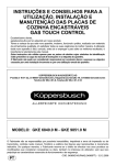
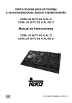
GB
Instruction manual for gas hobs
Model code: C981G
Model code: C1081G
Contact Caple on 0844 800 3830 or for spare parts www.4caple.co.uk
Dear Customer,
Thank you for choosing a Boretti product and congratulations on your purchase.
We are confident that your new appliance, manufactured with top quality materials, will respond
perfectly your requirements.
Although this appliance is extremely user-friendly, be sure to read this handbook carefully before
proceeding to install and use it.
This handbook contains information on installation, use and maintenance of your new appliance,
plus a series of practical tips.
THE MANUFACTURER
GENERAL PRECAUTIONS
Please read this instruction handbook carefully before installing and using the appliance.
This handbook must be kept in easy reach of the appliance for future consultation. If this appliance
is sold or transferred to another user, please give this handbook to the new user so that they can
learn how to use it correctly and be aware of the various warnings
This is a Class 3 appliance designed home use.
This appliance complies with the following Directives:
EEC 2009/142/CE (Gas) EEC 2004/108/CE (Electromagnetic Compatibility)
EEC 2006/95/CE (Low Voltage) EEC 89/109 (Contact with foods)
-- The appliance must be installed by a skilled and qualified installer, in conformity with statutory
legislation.
-- This appliance is designed for use by adults.
-- This appliance is not intended for use by persons (including children) with reduced or impaired
physical or mental capabilities, or persons lacking experience and awareness, unless they are
supervised or taught how to use the appliance by a responsible carer.
-- Do not allow children to play with the appliance.
-- Before powering the appliance, ensure that it is properly adjusted for the type of gas available
(see “installation”).
-- Before carrying out maintenance or cleaning operations, disconnect the appliance from the power
supply and allow it to cool.
-- Ensure air is able to circulate around gas appliances. Insufficient ventilation will lead to depletion
of the oxygen in the air in the place of installation.
-- In case of intense or prolonged use of the appliance, it may be necessary to increase ventilation,
for example by opening a window or increasing the power of extractor fans, if present.
-- Combustion products must be expelled from the place of installation through an extractor hood
or extractor fan (see “Installation”).
-- For any replacements or alterations that may be required, contact an authorised Technical
Assistance Centre and insist on the use of original spare parts.
IMPORTANT:
The product label, with the serial number, is affixed to the underside of the hob.
The Manufacturer cannot be held responsible for damage to property or personal injury resulting
from incorrect installation or improper, erroneous or unreasonable use of the appliance
2
HOBS - DESCRIPTION
MODEL: C981G
4
1
2
1 Rapid burner
2 Semi-rapid burner 3 Auxiliary burner
4 Triple crown burner 3000 W
1650 W
1000 W
4000 W
1 Rapid burner
2 Semi-rapid burner 3 Auxiliary burner
4 Triple crown burner 3000 W
1650 W
1000 W
4000 W
3
2
MODEL: C1081G
3
4
2
1
3
INSTRUCTIONS FOR THE INSTALLER
IMPORTANT NOTICE:
THE OPERATIONS INDICATED BELOW MUST BE CARRIED OUT BY QUALIFIED PERSONNEL ONLY, IN
CONFORMITY WITH STATUTORY LEGISLATION.
THE MANUFACTURER DECLINES ALL LIABILITY FOR INJURY TO PERSONS OR ANIMALS OR DAMAGE
TO PROPERTY DUE TO FAILURE TO COMPLY WITH THESE PRESCRIPTIONS.
INSTALLATION
Installing the hob
The appliance is designed to be built-in to a heat-resistant kitchen unit.
Kitchen unit side walls must be able to withstand temperatures of up to 75°C higher than room
temperature, in accordance with European regulations.
It is permissible to install the appliance next to a kitchen cabinet extending above the worktop on
one side only, either to the right or left. Any adjacent cabinet must be no less than 50 mm from the
edge of the hob.
The appliance must not be installed near inflammable materials, such as curtains, cloths, etc.
Cut an opening in the top of the kitchen unit observing the dimensions shown in fig. 1, maintaining
a distance of at least 50 mm between the edge of the appliance and adjacent walls.
MODEL
L (mm)
P (mm)
C981G
750
480
C1081G
950
365
If the hob is to be installed beneath a wall-mounted kitchen cabinet, ensure there is a minimum
clearance of 760 mm between the worktop and the underside of the cabinet.
It is good practice to isolate the appliance from the cupboard below in the kitchen unit by means of
a separator, leaving a well space of at least 10 mm in depth. (fig. 2).
If the hob is installed over an oven, precautions must be taken to guarantee installation in
accordance accident prevention standards. Pay particular attention to the position of the electric
cable and gas supply hose: they must not touch any hot parts of the oven. Moreover, if the hob is
installed over an oven without a forced cooling system, to ensure adequate ventilation air vents
must be provided with lower intake surface area of at least 200 cm2 and upper outlet surface area
of at least 60 cm2.
Fixing the hob
Each hob is supplied with a special gasket and a set of brackets to be used for securing it to the
worktop.
1
2
4
INSTRUCTIONS FOR THE INSTALLER
To install the hob, proceed as follows:
-- Remove the pan supports and burners from the hob.
-- Turn the appliance upside down and fit gasket (S) around the outer edge (fig. 3).
-- Place the hob in the unit opening and fix it with screws (V) of brackets (G) (fig. 4).
Installation environment
This appliance is not equipped with a combustion products exhaustion system. Fumes must
therefore be exhausted to outside the building by means of an extractor hood or extractor fan
designed to start as soon as the appliance is set into operation.
The room in which the appliance is installed must be naturally ventilated to allow correct gas
combustion and room ventilation; the minimum volume of air required is 20 m3.
Fresh air must be drawn through permanent vents in the walls communicating with the exterior.
Ventilation may also be supplied via an adjacent room in compliance with standards in force.
Wall vents must have a minimum surface area 200 cm2.
Gas Connection
Make sure that the appliance is set up for the available gas type (see the label under the appliance).
Follow the instructions indicated in “Gas conversion and adjustment” if the appliance must be
adapted for use with different gas types.
The appliance must be connected to the gas supply by means of a rigid metal pipe, in compliance
with standards in force, or a seamless flexible steel pipe in compliance with standards in force.
Certain models are supplied with two unions:
a cylindrical union (A) and a conical union (B) (fig.5). Choose the appropriate union according to the
country of installation.
The weight of the connecting pipe must not be borne by the gas train.
Once installation is complete, apply a soapy solution to the seal to check that it is gas tight.
3
5
4
5
INSTRUCTIONS FOR THE INSTALLER
Electrical Connection
The appliance must be connected to the electrical mains by qualified personnel and in conformity
with statutory legislation.
The voltage of the electric supply must correspond to the value indicated on the label affixed to the
underside of the appliance.
Make sure that the electric system has an efficient earth connection in compliance with regulations
and legislation. This appliance must be earthed.
IMPORTANT: if the household electrical system does not meet specifications or does not have an
efficient earth connection, the appliance will not operate.
If the appliance is not fitted with a plug, connect a standard plug to the power cable.
If the appliance is to be wired directly to the mains supply, a disconnect device must be interposed
having a sufficient contact gap to allow complete isolation also in category III surge conditions, in
accordance with installation regulations.
In case of a power failure, the appliance will not operate and the burners cannot be lit using
matches or external igniters.
However, the appliance can continue to operate correctly if the power cord is connected to an
uninterruptible power supply. In this case, operation is normal.
GAS CONVERSION AND ADJUSTMENTS
If the appliance is prearranged for a type of gas different from the available type, the burner
nozzles must be changed and the control card must be set up with the parameters relative to the
new configuration.
Changing the nozzles
Choose the required nozzles with reference to the following “Technical Specifications” table.
Proceed as follows:
-- Remove the pan stands and burners from the hob.
-- Unscrew nozzles U (fig.6) and U1/U2 (fig.7) using a socket spanner (L), and replace with the correct
nozzle for the available gas type.
-- Secure the nozzle without over-tightening.
6
7
6
INSTRUCTIONS FOR THE INSTALLER
Choosing the type of gas (5-burner version)
The hob can be configured for use with natural gas or LPG. To activate the gas selection procedure
the hob must be switched on with all of the burners off.
Press the “+” and “-” buttons simultaneously for approx. 3 seconds as shown in the figure above.
The burner level display will switch off and “Met” or “LPG” will appear on the timer display,
depending on the current configuration.
met
Select the desired setting using the “+” and “-” buttons.
met
To complete the procedure, press the timer button.
By activating this function, any other previously set burner switch off times will be cancelled.
7
INSTRUCTIONS FOR THE INSTALLER
Minimum flow adjustment (5-burner version)
The minimum flow is correctly adjusted when the flame remains lit without a pot on the pan
support in position 1 of the burner control.
To adjust the minimum flow of each burner, proceed as follows:
MIN
Press the “+” and “-” buttons simultaneously for approx. 3 seconds as shown in the figure above.
“MIN” will appear on the display indicating the activation of the adjustment procedure.
At this stage, select the burner to be adjusted using the “+” and “-” buttons. By pressing these
buttons repeatedly, a LED will light up showing the selected burner
To confirm the selected burner, press the timer button.
The selected burner will light on the minimum setting. To increase or decrease the minimum flow,
use the “+” and “-” buttons of the specific burner.
During the adjustment procedure, the selected burner display will show “-” if the set minimum level
corresponds to the factory setting.
^ or v will flash on the display if the flow rate is respectively higher or lower than the preset flow
rate.
To go to the next burner, repeat the procedure from the second figure.
After adjusting all the burners, press the timer button again to exit the procedure. The minimum
flow settings are saved and will be used each time you use the appliance.
8
INSTRUCTIONS FOR THE INSTALLER
Choosing the type of gas (4-burner version)
The hob can be configured for use with natural gas or LPG. To activate the gas selection procedure
the hob must be switched on with all of the burners off.
Press the “-” buttons simultaneously for approx. 3 seconds as shown in the figure above. The burner
level display will switch off and “Met” or “LPG” will appear on the timer display, depending on the
current configuration
met
Select the desired setting using the “+” and “-” buttons.
met
To end the procedure, press the timer button.
By activating this function, any other previously set burner switch off times will be cancelled.
9
INSTRUCTIONS FOR THE INSTALLER
Minimum flow adjustment (4-burner version)
The minimum flow is correctly adjusted when the flame remains lit without a pot on the pan
support in position 1 of the burner control.
To adjust the minimum flow of each burner, proceed as follows:
min
Press the “+” and “-” buttons simultaneously for approx. 3 seconds as shown in the figure above.
“MIN” will appear on the display indicating the activation of the adjustment procedure.
At this stage, select the burner to be adjusted using the “+” and “-” buttons. By pressing these
buttons repeatedly, a LED will light up showing the selected burner.
To confirm the selected burner, press the timer button.
The selected burner will light on the minimum setting. To increase or decrease the minimum flow,
use the “+” and “-” buttons of the specific burner.
During the adjustment procedure, the selected burner display will show “-” if the set minimum level
corresponds to the factory setting.
“^” or “v” will flash on the display if the flow rate is respectively higher or lower than the preset
flow rate.
To go to the next burner, repeat the procedure from the second figure.
After adjusting all the burners, press the timer button again to exit the procedure. The minimum
flow settings are saved and will be used each time you use the appliance.
10
INSTRUCTIONS FOR THE INSTALLER
MAINTENANCE
Replacing the power supply cable
Should it be necessary to replace the power supply
cable, use a standard type H05VV-F or H05RR-F cable
with a section of 3 x 0.75 mm2.
The connection to the terminal board must be carried
out as shown in the figure on the right:
Brown wire L
(live)
Blue wire N (neutral)
Green-yellow wire
(earth)
TECHNICAL SPECIFICATIONS TABLE
NOZZLE
DIAMETER
REGULATORS BYPASS DIAMETER
mbar
g/h
L/h
1/100 mm
1/100 mm
Max.
Min.
28-30
218
-
87
42
3000
950
G31
37
214
-
87
42
3000
950
G20
20
-
286
129
Reg.
3000
950
GAS
N°
DESIGNATION
G30
1
2
3
4
RAPID
SEMI-RAPID
AUXILIARY
TRIPLE CROWN
WORKING
PRESSURE
HEAT INPUT
BURNERS
HEAT INPUT
(W)
G25
25
-
332
132
Reg.
3000
950
G30
28-30
120
-
65
31
1650
600
G31
37
118
-
65
31
1650
600
G20
20
-
157
97
Reg.
1650
600
G25
25
-
183
100
Reg.
1650
600
G30
28-30
73
-
50
27
1000
450
G31
37
71
-
50
27
1000
450
G20
20
-
95
77
Reg.
1000
450
G25
25
-
111
80
Reg.
1000
450
G30
28-30
255
-
46 / 65
60
4000
2100
G31
37
250
-
46 / 65
60
4000
2100
G20
20
-
334
71 / 95
Reg.
4000
2100
G25
25
-
443
71 / 100
Reg.
4000
2100
11
INSTRUCTIONS FOR THE USER
GENERAL PRECAUTIONS
Using the burners
To obtain the maximum efficiency without wasting gas, the pot diameter must be suitable in
relation to the burner (see the following table), to avoid the flame extending beyond the bottom
of the pot.
Use the maximum capacity to quickly make the liquids reach the boiling temperature, and the
reduced capacity to heat food or maintain the boil.
Burners
Power (W)
Ø Pot
Auxiliary
1000
10 - 14 cm
Semi-rapid
1650
16 - 18 cm
Rapid
3000
20 - 22 cm
Triple crown
4000
24 - 26 cm
Precautions
-- The appliance is equipped with a device that attempts to re-light the burner if the flame blows out
accidentally. If the burner does not light after 3 attempts, it will lock out and the letter “b” will appear
on the relevant display. In this case, perform the reset procedure as described below.
-- Fat and oil can catch fire when overheated so use caution when cooking in fat or oil.
-- Do not use sprays near the appliance when it is in operation.
-- Do not place unstable or deformed pots on pan support: risk of overturning or spillage of contents.
-- Make sure pot handles are positioned correctly.
-- When the burner is lit, check that the flame is even and, before removing pots, always turn down the
flame or switch off the burner..
CLEANING
Before cleaning, disconnect the appliance from the electricity supply.
Do not clean the appliance with steam cleaners.
The appliance should be cleaned only when it is cold.
Glass ceramic and steel parts
Remove food residues and grease spatters from the cooking surface using the special scraper
(optional).
Then clean the area using SIDOL, STAHLFIX or a similar product and a paper towel.
Do not use sponge scourers or chemical detergents.
Burners and pan supports
These parts can be removed for easier cleaning.
The burners must be washed with a sponge and soapy water or with a mild detergent, dried thoroughly
and lodged in their seat perfectly.
Make sure that the burner cap holes are not clogged.
Ensure the safety valve probe and ignition electrode are always perfectly clean to ensure optimal
operation.
The pan supports can be washed in a dishwasher.
12
INSTRUCTIONS FOR THE USER
All operations concerning installation, adjustment and adaptation to the available
gas type must be carried out by a qualified technician, in compliance with statutory
legislation.
The specific instructions are given in the section of the handbook reserved for the
installer.
USING THE APPLIANCE - 5-BURNER VERSION
The symbols printed above each burner control show the correspondence between the control and the
burner.
Standby mode
After connecting the appliance to the power supply, it will perform a brief self-diagnosis routine
and touch panel calibration (all displays and LEDs remain illuminated for a few seconds). When this
procedure is completed the display will be blank.
Switching on the hob
To switch on the hob, hold the ON/OFF button for at
least 2 seconds.
The appliance will switch on and the five burner
displays will show power level 0, meaning that the
burners are off.
Lighting a burner
To light a burner, hold down the “+” and “-”
buttons on the control panel simultaneously for at
least 1 second. After a few seconds, the selected
burner will light and power setting 5 will be selected
automatically. The associated indicator light will
remain on as long as the burner is lit.
All burners for which the timer has not been set will
turn off automatically after 4 hours of continuous
operation.
5
Adjusting burner flame levels
After lighting the burner, press “+” to turn up the power level and “-” to turn it down. For
continuous variation of the power level hold down the “+” or “-” button and release it at the
desired level. Power levels can be adjusted from 1 to 9.
Burner response differs during upward and downward power adjustment:
-- when the level is increased from 1 to 9, after the adjustment the burner first assumes power level
9 and then assumes the set level;
-- when the level is decreased from 9 to 1, the adjustment is progressive.
Turning off a burner
Briefly press the “+” and “-” buttons for the desired burner simultaneously. The power level
indicator shows letter “H” indicating that the burner is still hot. This indication is cleared after a few
minutes.
13
INSTRUCTIONS FOR THE USER
Turning off all burners
To turn off all burners simultaneously, briefly press the ON/OFF button: the appliance will enter
standby mode.
Setting the clock
After a power failure, the hob clock must be reset.
To set the clock, simultaneously press and hold the
buttons shown in the figure for at least 3 seconds.
The flashing digits on the left of the dot indicate
the hour and the digits on the right indicate the
minutes. Increase or decrease the hour using the “+”
and “-” buttons.
Hold down the “+” or “-” button to increase or
decrease the hours digits rapidly.
To set the minutes, press the button with the clock
symbol again. The digits on the right of the dot will
start flashing; set the minutes as described above.
Press the button with the clock symbol again to save
the set time.
08.00
Burner reset
The burners may lock out due to external faults (for example, in the event of either a power or gas
supply failure).
The display of each locked out burner will show the letter “b”. To reset the burners, simultaneously
hold down the “-” and “key” buttons as shown in the figure for at least 2 seconds.
Once the burners have been reset, they will be set to level 0, ready to be turned on again.
N.B.: If you repeat the reset procedure 5 consecutive times within 15 minutes, the message FLT06
will be displayed and no other reset requests will be accepted for the following 15 minutes.
Touch panel lock
To activate this function, press the “key” button
for at least 2 seconds. All burner power levels will
remain in their current status. When the touch panel
is locked the decimal points light up in the display
of each burner. When the touch panel is locked, it
is not possible to change the burner power levels or
change the timer settings, but it is possible to switch
the hob off by pressing the ON/OFF button. Locked
burners cannot be reset when the touch panel lock is
activated. The touch panel must be unlocked before
performing the burner reset procedure.
14
5.
INSTRUCTIONS FOR THE USER
Touch panel unlock
5
5
5
5
5
To unlock the touch panel, press the “key” button and the “+” button of the LH burner for at
least 2 seconds. When the touch panel is unlocked the decimal points switch off in the power level
displays.
Programming burner off time
Each burner can be programmed to operate for a specified time, after which it switches off
automatically.
To program the timer of a specific burner, press
the “timer” button. The position of each burner is
shown by means of a LED on the control panel. The
LED will illuminate to indicate that the burner has
been selected for programming. Select the burner
with which to associate the timer using the “+”
and “-” buttons. The timer display will show 00.00,
meaning that the timer of the selected burner is not
activated.
Press the “key” button again. The flashing digits on the left of the dot indicate the hour and the
digits on the right indicate the minutes. Increase or decrease cooking time from 0 to 9 hours using
the “+” and “-” buttons. Hold down the “+” or “-” button to increase or decrease the hours digits
rapidly. To set the minutes, press the “key” button again. The digits on the right of the dot start
flashing. Set the minutes as described above for the hours.
When programming the cooking time you can cancel the current setting at any time by pressing the
“+” and “-” buttons simultaneously.
If the time is set to zero, the timer is deactivated. To confirm the time displayed, press the “key”
button.
At this point the indicators exclusively of the burners with active timer will continue flashing.
Press the “timer” button to access programming mode and display the time remaining before the
burner switches off or change the current setting. If no button is pressed for more than 10 seconds,
the system automatically quits programming mode and restores the main display. Any settings in
progress on the selected burner are retained and the associated timer remains active. The timer can
be programmed with the burner OFF or ON, and it will start counting from when the set cooking
time is confirmed. Once the set cooking time has elapsed, the timer-controlled burner will switch
off and a series of beeps will be emitted. Switching off a burner also deactivates the associated
timer (if programmed).
00.00
15
INSTRUCTIONS FOR THE USER
USING THE APPLIANCE - 4-BURNER VERSION
The symbols printed above each burner control show the correspondence between the control and the
burner.
Standby mode
After connecting the appliance to the power supply, it will perform a brief self-diagnosis routine
and touch panel calibration (all displays and LEDs remain illuminated for a few seconds). When this
procedure is completed the display will be blank.
Switching on the hob
To switch on the hob, hold the ON/OFF button for at
least 2 seconds.
The appliance will switch on and the five burner
displays will show power level 0, meaning that the
burners are off.
Lighting a burner
To light a burner, hold down the “+” and “-”
buttons on the control panel simultaneously for at
least 1 second. After a few seconds, the selected
burner will light and power setting 5 will be selected
automatically. The associated indicator light will
remain on as long as the burner is lit.
All burners for which the timer has not been set will
turn off automatically after 4 hours of continuous
operation.
5
Adjusting burner flame levels
After lighting the burner, press “+” to turn up the power level and “-” to turn it down. For
continuous variation of the power level hold down the “+” or “-” button and release it at the
desired level. Power levels can be adjusted from 1 to 9.
Burner response differs during upward and downward power adjustment:
-- when the level is increased from 1 to 9, after the adjustment the burner first assumes power level
9 and then assumes the set level;
-- when the level is decreased from 9 to 1, the adjustment is progressive.
Turning off a burner
Briefly press the “+” and “-” buttons for the desired burner simultaneously. The power level
indicator shows letter “H” indicating that the burner is still hot. This indication is cleared after a few
minutes.
16
INSTRUCTIONS FOR THE USER
Turning off all burners
To turn off all burners simultaneously, briefly press the ON/OFF button: the appliance will enter
standby mode.
Setting the clock
After a power failure, the hob clock must be reset.
To set the clock, simultaneously press and hold the
buttons shown in the figure for at least 3 seconds.
The flashing digits on the left of the dot indicate
the hour and the digits on the right indicate the
minutes. Increase or decrease the hour using the “+”
and “-” buttons.
Hold down the “+” or “-” button to increase or
decrease the hours digits rapidly.
To set the minutes, press the button with the clock
symbol again. The digits on the right of the dot will
start flashing; set the minutes as described above.
Press the button with the clock symbol again to save
the set time.
08.00
Burner reset
The burners may lock out due to external faults (for example, in the event of either a power or gas
supply failure).
The display of each locked out burner will show the letter “b”. To reset the burners, simultaneously
hold down the “-” and “key” buttons as shown in the figure for at least 2 seconds.
Once the burners have been reset, they will be set to level 0, ready to be turned on again.
N.B.: If you repeat the reset procedure 5 consecutive times within 15 minutes, the message FLT06
will be displayed and no other reset requests will be accepted for the following 15 minutes.
Touch panel lock
To activate this function, press the “key” button
for at least 2 seconds. All burner power levels will
remain in their current status. When the touch panel
is locked the decimal points light up in the display
of each burner. When the touch panel is locked, it
is not possible to change the burner power levels or
change the timer settings, but it is possible to switch
the hob off by pressing the ON/OFF button. Locked
burners cannot be reset when the touch panel lock is
activated. The touch panel must be unlocked before
performing the burner reset procedure.
17
5.
INSTRUCTIONS FOR THE USER
Touch panel unlock
5
5
5
5
To unlock the touch panel, press the “key” button and the “+” button of the LH burner for at
least 2 seconds. When the touch panel is unlocked the decimal points switch off in the power level
displays.
Programming burner off time
Each burner can be programmed to operate for a specified time, after which it switches off
automatically.
To program the timer of a specific burner, press
the “timer” button. The position of each burner is
shown by means of a LED on the control panel. The
LED will illuminate to indicate that the burner has
been selected for programming. Select the burner
with which to associate the timer using the “+”
and “-” buttons. The timer display will show 00.00,
meaning that the timer of the selected burner is not
activated.
Press the “key” button again. The flashing digits on the left of the dot indicate the hour and the
digits on the right indicate the minutes. Increase or decrease cooking time from 0 to 9 hours using
the “+” and “-” buttons. Hold down the “+” or “-” button to increase or decrease the hours digits
rapidly. To set the minutes, press the “key” button again. The digits on the right of the dot start
flashing. Set the minutes as described above for the hours.
When programming the cooking time you can cancel the current setting at any time by pressing the
“+” and “-” buttons simultaneously.
If the time is set to zero, the timer is deactivated. To confirm the time displayed, press the “key”
button.
At this point the indicators exclusively of the burners with active timer will continue flashing.
Press the “timer” button to access programming mode and display the time remaining before the
burner switches off or change the current setting. If no button is pressed for more than 10 seconds,
the system automatically quits programming mode and restores the main display. Any settings in
progress on the selected burner are retained and the associated timer remains active. The timer can
be programmed with the burner OFF or ON, and it will start counting from when the set cooking
time is confirmed. Once the set cooking time has elapsed, the timer-controlled burner will switch
off and a series of beeps will be emitted. Switching off a burner also deactivates the associated
timer (if programmed)
00.00
18
INSTRUCTIONS FOR THE USER
Electronic self-diagnosis
The circuit boards perform continuous self-diagnosis. In the event of hardware faults or
malfunctions in the circuit board that could be dangerous for the end user, the device will assume
“safe” mode, the solenoid valves are deactivated and the display shows the relative fault code.
Generally, the default operating parameters are restored by disconnecting and reconnecting the
power supply. This action will resolve most problems.
If the fault persists, contact your nearest service centre.
Fault types and codes are shown in the following table.
Displayed fault
code
Solution
Single burner locked out
b
Perform reset procedure as
described in previous sections.
Spurious flame / flame detection circuit fault
on single burner
F
Fault type
Main valve control circuit fault
FLt00
Reference voltage circuit fault
FLt01
Watchdog circuit fault
FLt02
Microcontroller ports fault
FLt03
Eeprom fault
FLt04
Valve drive circuit fault
FLt05
Max 5 resets in 15 minutes exceeded
FLt06
Perform reset procedure as
described in previous sections.
Supply circuit fault
FLt08
Disconnect electrical power
supply and then reconnect after
a few seconds.
If the problem persists, contact
the service centre.
Resonator fault / Generic fault
FLt09
Perform reset procedure as
described in previous sections.
All burners locked out
FLt0A
Perform reset procedure as
described in previous sections.
Control logic communication errors
FLt0C
Touch panel control error
FLt0E
19
Disconnect electrical power
supply and then reconnect after
a few seconds.
If the problem persists, contact
the service centre.
Disconnect electrical power
supply and then reconnect after
a few seconds.
If the problem persists, contact
the service centre.
The crossed-out dustbin symbol reported on the appliance indicates that the appliance
must be disposed of separately from other domestic refuse at the end of its useful life.
It must therefore be delivered to a waste recycling centre specifically for electric and
electronic equipment or returned to the retailer at the moment of purchase of a new
equivalent appliance.
The user is responsible for delivering the appliance to the appropriate collection centre at the
end of its useful life, Failure to do so may result in a fine, as provided for by laws governing waste
disposal.
Differential collection of waste products for eventual recycling, treatment and environmentally
friendly disposal helps reduce possible negative effects on the environment and health, and also
enables the materials making up the product to be recycled.
For more detailed information on the available refuse collection systems, refer to the local
Municipal Solid Waste disposal centre or the shop where the product was purchased.
Producers and importers are responsible for fulfilling their obligations as regards recycling,
treatment and environmentally friendly disposal by directly or indirectly participating in the
collection system.
The manufacturing firm refuses all responsibility for any possible imprecision in this booklet, due
to misprints or clerical errors. It reserves the right to make all the changes that it will consider
necessary in its own products, without affecting the essential characteristics of functionality and safety.
20
COD. 208405-00 - 26.10.2010
This product complies with EU Directive 2002/96/EC.