1
Installation and Commissioning
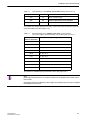
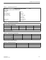
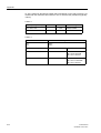
Table 4-2
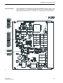
Internal Settings of the 7VH600*-0*A10-1AA0 (Setting step size of 6 V)
Jumper location
Position
Meaning
X12
1-2
LED 4 not active (test)
X15
2-3
Buswire supervision circuit activated
X15
1-2
Buswire supervision circuit disabled
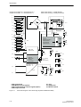
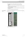
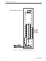
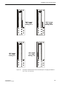
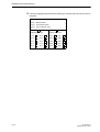
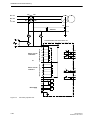
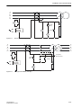
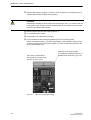
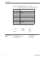
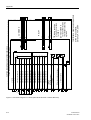
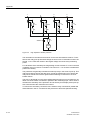
To increase the voltage setting on the relay, remove the short circuit links on the connector as follows (see also Figure 4-3):
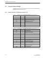
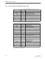
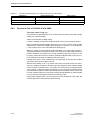
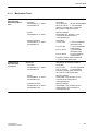
Table 4-3
External Settings of the 7VH600*-0*A10-1AA0 on the Connector
with a max. Tripping Threshold setting of 60 V (setting step size of 6 V)
Short Circuit Links
fitted on Terminals
Relay setting (AC)
8-18
5.5 - 6 - 7.5 V
10-18
10 - 12 - 14 V
12-18
16 - 18 - 20 V
14-18
22 - 24 - 26 V
16-18
28 - 30 - 33 V
8-16
33 - 36 - 39 V
10-16
39 - 42 - 45 V
12-16
45 - 48 - 51 V
14-16
51 - 54 - 57 V
no S.C. link
57 - 60 - 63 V
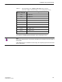
The maximum settable tripping threshold is 60 V with steps of 6 V.
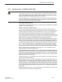
Note:
Removed jumpers that are not currently needed can be parked on the other side of
the terminal.
If the setting has to be modified at a later stage, the needed jumpers are then available
immediately on the device.
7VH60 Manual
C53000-B1176-C136-3
4-7