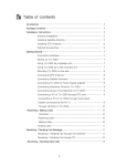
1
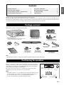
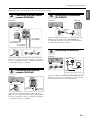
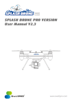
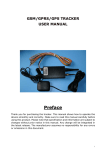
UC
English
Français
Home Theater Package
Pack Numérique Home Cinéma
YHT-494
(HTR-3063 + NS-BR300 +
NS-B285 + NS-SW280)
Owner’s Manual
Mode d’emploi
IMPORTANT SAFETY INSTRUCTIONS
CAUTION
RISK OF ELECTRIC SHOCK
DO NOT OPEN
CAUTION: TO REDUCE THE RISK OF ELECTRIC
SHOCK, DO NOT REMOVE COVER (OR BACK).
NO USER-SERVICEABLE PARTS INSIDE. REFER
SERVICING TO QUALIFIED SERVICE PERSONNEL.
• Explanation of Graphical Symbols
1.
2.
3.
4.
5.
6.
7.
8.
9.
The lightning flash with arrowhead symbol, within an
equilateral triangle, is intended to alert you to the
presence of uninsulated “dangerous voltage” within the
product’s enclosure that may be of sufficient magnitude
to constitute a risk of electric shock to persons.
The exclamation point within an equilateral triangle is
intended to alert you to the presence of important
operating and maintenance (servicing) instructions in
the literature accompanying the appliance.
10.
11.
12.
IMPORTANT
Please record the serial number of this unit in the space below.
MODEL:
Serial No.:
The serial number is located on the rear of the unit. Retain this
Owner’s Manual in a safe place for future reference.
13.
14.
Read these instructions.
Keep these instructions.
Heed all warnings.
Follow all instructions.
Do not use this apparatus near water.
Clean only with dry cloth.
Do not block any ventilation openings. Install in accordance
with the manufacturer’s instructions.
Do not install near any heat sources such as radiators, heat
registers, stoves, or other apparatus (including amplifiers)
that produce heat.
Do not defeat the safety purpose of the polarized or
grounding-type plug. A polarized plug has two blades with
one wider than the other. A grounding type plug has two
blades and a third grounding prong. The wide blade or the
third prong are provided for your safety. If the provided plug
does not fit into your outlet, consult an electrician for
replacement of the obsolete outlet.
Protect the power cord from being walked on or pinched
particularly at plugs, convenience receptacles, and the point
where they exit from the apparatus.
Only use attachments/accessories specified by the
manufacturer.
Use only with the cart, stand, tripod, bracket,
or table specified by the manufacturer, or sold
with the apparatus. When a cart is used, use
caution when moving the cart/apparatus
combination to avoid injury from tip-over.
Unplug this apparatus during lightning
storms or when unused for long periods of time.
Refer all servicing to qualified service personnel. Servicing
is required when the apparatus has been damaged in any way,
such as power-supply cord or plug is damaged, liquid has
been spilled or objects have fallen into the apparatus, the
apparatus has been exposed to rain or moisture, does not
operate normally, or has been dropped.
FCC INFORMATION (for US customers)
1 IMPORTANT NOTICE: DO NOT MODIFY THIS
UNIT!
This product, when installed as indicated in the instructions
contained in this manual, meets FCC requirements.
Modifications not expressly approved by Yamaha may void
your authority, granted by the FCC, to use the product.
2 IMPORTANT: When connecting this product to
accessories and/or another product use only high quality
shielded cables. Cable/s supplied with this product MUST be
used. Follow all installation instructions. Failure to follow
instructions could void your FCC authorization to use this
product in the USA.
3 NOTE: This product has been tested and found to comply
with the requirements listed in FCC Regulations, Part 15 for
Class “B” digital devices. Compliance with these
requirements provides a reasonable level of assurance that
your use of this product in a residential environment will not
result in harmful interference with other electronic devices.
This equipment generates/uses radio frequencies and, if not
installed and used according to the instructions found in the
users manual, may cause interference harmful to the operation
of other electronic devices.
i En
Compliance with FCC regulations does not guarantee that
interference will not occur in all installations. If this product
is found to be the source of interference, which can be
determined by turning the unit “OFF” and “ON”, please try
to eliminate the problem by using one of the following
measures:
Relocate either this product or the device that is being
affected by the interference.
Utilize power outlets that are on different branch (circuit
breaker or fuse) circuits or install AC line filter/s.
In the case of radio or TV interference, relocate/reorient the
antenna. If the antenna lead-in is 300 ohm ribbon lead,
change the lead-in to coaxial type cable.
If these corrective measures do not produce satisfactory
results, please contact the local retailer authorized to
distribute this type of product. If you can not locate the
appropriate retailer, please contact Yamaha Electronics
Corp., U.S.A. 6660 Orangethorpe Ave., Buena Park, CA
90620.
The above statements apply ONLY to those products
distributed by Yamaha Corporation of America or its
subsidiaries.
Precautions
1. To assure the finest performance, please read this manual
carefully. Keep it in a safe place for future reference.
2. Install the speakers in a cool, dry, clean place – away from
windows, sources of heat, sources of excessive vibration,
dust, moisture or cold. Avoid sources of electrical humming
(e.g., transformers and motors). To prevent fire or electric
shock, do not expose the speakers to rain or water.
3. To prevent the enclosure from warping or discoloring, do not
expose the speakers to direct sunlight or excessive humidity.
4. Avoid installing the speakers where foreign objects may fall
onto them and/or where they may be exposed to liquid
dripping or splashing.
5. Do not place the following objects on top of the speakers:
– Other components, as they might damage or discolor the
surface of the speakers.
– Burning objects (e.g., candles), as they might cause fire,
damage to the speakers or personal injury.
– Containers of liquid, as they might spill and cause electric
shock to the user or damage to the speakers.
6. Do not place the speakers where they are liable to be knocked
over or struck by falling objects. Stable placement will also
ensure better sound performance.
7. Placing the speakers on the same shelf or rack as the
turntable can result in feedback.
8. Any time you note distortion, reduce the volume control on
your amplifier to lower setting. Never allow your amplifier to
be driven into “clipping”. Otherwise, the speakers may be
damaged.
9. When using an amplifier with a rated output power higher
than the nominal input power of the speakers, care should be
taken not to exceed the maximum input of the speakers.
10. Do not attempt to clean the speakers with chemical solvents
as this might damage the finish. Use a clean, dry cloth.
11. Do not attempt to modify or fix the speakers. Contact
qualified Yamaha service personnel when service is needed.
The cabinet should never be opened for any reason.
12. Be sure to read the “Troubleshooting” section regarding
common operating errors before concluding that the speakers
are faulty.
13. Secure placement or installation is the owner’s
responsibility. Yamaha is not liable for accidents caused
by improper placement or installation of speakers.
For NS-SW280
WARNING
TO REDUCE THE RISK OF FIRE OR ELECTRIC SHOCK,
DO NOT EXPOSE THIS APPLIANCE TO RAIN OR
MOISTURE.
1. Do not operate this unit upside down. It may overheat,
possibly causing damage.
2. Do not use excessive force on switches, controls or
connection wires. When moving this unit, first disconnect the
power plug and the wires connected to other equipment.
Never pull the wires themselves.
3. Never put a hand or a foreign object into the port located on
the right side of this unit. When moving this unit, do not hold
the port, as it might cause personal injury and/or damage to
this unit.
4. Since this unit has a built-in power amplifier, heat radiates
from the rear panel. Place the unit away from walls, allowing
at least 20 cm (8") of space above, behind and on both sides
of the unit to prevent fire or damage. Furthermore, do not
position the unit with the rear panel facing down on the floor
or other surfaces.
5. When using a humidifier, be sure to avoid condensation
inside this unit by allowing enough space around the unit and
avoiding excess humidification. Condensation might cause
fire, damage to the unit, and/or electric shock.
6. Do not cover the rear panel of this unit with a newspaper,
tablecloth, curtain, etc. to avoid obstructing heat radiation. If
the temperature inside the unit rises, it may cause fire,
damage to the unit, or personal injury.
7. Do not plug this unit into a wall outlet until all connections
are complete.
8. The voltage to be used must match that specified on the rear
panel. Using this unit with a voltage higher than specified is
dangerous and may cause fire, damage to the unit, and/or
personal injury. Yamaha is not responsible for damage resulting from use of this unit with a voltage other than specified.
9. Super-bass sound reproduced by this unit may cause a
turntable to generate audio feedback. In this case, move the
unit away from the turntable.
10. This unit may be damaged if certain sounds are continuously
output at high volume level. For example, if 20 Hz–50 Hz
sine waves from a test disc or bass sounds from an electronic
instrument, etc. are continuously output, or if a turntable
stylus touches the surface of a disc, reduce the volume level
to prevent the unit from being damaged.
11. If you hear distorted noise (i.e., unnatural, intermittent
“rapping” or “hammering” sounds) from this unit, reduce the
volume level. Extremely loud movie soundtrack low
frequency, bass-heavy sounds, or similarly loud popular
music passages can damage this unit.
12. Vibration generated by super-bass sound may distort images
on a TV. In this case, move the unit away from the TV set.
13. When disconnecting the power cord from the wall outlet,
grasp the plug; do not pull the cord.
14. When you plan not to use this unit for a long period of time
(i.e. vacation, etc.), disconnect the AC power plug from the
wall outlet.
15. Install this unit near the wall outlet and where the AC power
plug can be reached easily.
ii En
English
Please read the following operating precautions before use. Yamaha will not be held responsible for any damage and/or injury caused by
not following the cautions below.
Precautions
This unit is not disconnected from the AC power source as long
as it is connected to the wall outlet, even if this unit itself is
turned off. In this state, this unit is designed to consume a very
small quantity of power.
FOR CANADIAN CUSTOMERS
To prevent electric shock, match wide blade of plug to wide
slot and fully insert.
This Class B digital apparatus complies with Canadian
ICES-003.
iii En
We Want You Listening For A Lifetime
Yamaha and the Electronic Industries
Association’s Consumer Electronics Group want
you to get the most out of your equipment by
playing it at a safe level. One that lets the sound
come through loud and clear without annoying
blaring or distortion – and, most importantly,
without affecting your sensitive hearing. Since hearing damage
from loud sounds is often undetectable until it is too late, Yamaha
and the Electronic Industries Association’s Consumer Electronics
Group recommend you to avoid prolonged exposure from
excessive volume levels.
Contents
Using the subwoofer............................................6
Wall-mounting the speakers ..............................7
Troubleshooting ...................................................8
Specifications........................................................8
Thank you for choosing the Yamaha YHT-494 Home Theater Package.
The Yamaha YHT-494 Home Theater Package includes everything you need to add great sound to your home theater. By following
the instructions in this manual, you’ll have your home theater set up in no time and be enjoying music and movies like never before.
See also the AV Receiver’s owner’s manual for full instructions and precautions for AV Receiver.
Package contents
Make sure the package contains the following items.
TUNING
Surround speakers (NS-B285)
AM
FM
VOLUME
PRESET
INFO
MEMORY
SCENE
CD
BD
DVD
RADIO
TV
VIDEO AUX
STRAIGHT
PROGRAM
TONE CONTROL
INPUT
VIDEO
L
AUDIO
R
PORTABLE
PHONES
SILENT CINEMA
AV Receiver (HTR-3063)*
* See the AV Receiver’s owner’s manual for a list of
the items supplied with the AV Receiver.
Subwoofer (NS-SW280)
Stands and screws for
surround speakers (NS-B285)
Front/center speaker (NS-BR300)
AM antenna
FM antenna
Subwoofer cable
5 m (16 ft.) x1
Speaker cable
25 m (82 ft.) x1
YHT-494
Stands and screws
for front/center
speaker (NS-BR300)
Non-skid pads
for front/center
speaker (NS-BR300)
Mounting template
for front/center
speaker (NS-BR300)
Owner’s manual
Note
• Only the items required to complete the instalation explained in this manual are shown here.
Positioning the speakers
Before you connect the speakers, place each speaker in its respective location.
Speaker positioning is very important as it affects the overall sound quality of the
system. Place the speakers in locations that will optimize the sound quality at
your listening position. Refer to the illustration.
The position of the subwoofer is not as critical as the position of the other
speakers because sub-bass sounds are not very directional.
Notes
• Placing the speakers too close to a CRT-type TV may impair the picture color
or cause a buzzing noise. In this case, move the speakers at least 20 cm (8")
away from the TV. This is not an issue with LCD and plasma TVs.
• See page 7 for information on wall-mounting the speakers.
Subwoofer
Front/
center
Surround left
Surround right
1 En
English
Package contents.................................................1
Positioning the speakers ....................................1
Connecting the speakers and antennas ..........2
Connecting AV components ..............................4
Connecting the speakers and antennas
1
Preparing the cables and
speakers
Once you’ve positioned the speakers, you’ll need to cut the 25meter (82 ft.) speaker cable to make three cables for
connecting the front/center speaker and two cables for the
surround speakers.
1 Cut the included speaker cable to suitable lengths
for the front/center speaker and surround speakers.
You need five cables.
■ Attaching the speaker stands
• Surround speakers (NS-B285)
Attach the included speaker stands with screws when placing
the surround speakers on a flat surface, as shown below.
Screw for
the NS-B285
speaker stands
2 Remove about 10 mm (3/8") of insulation from the
end of each speaker cable.
• Front/center speaker (NS-BR300)
3 Twist the bare wires tightly.
If you place the front/center speaker (NS-BR300) at the base of
your TV, attach the included stands. If you use it without the
stands, affix the included non-skid pads.
10 mm (3/8")
Good
No Good
Notes
• Make the speaker cables as short as possible. Do not bundle
or roll up excess cable.
• Twist the bare wires tightly so the individual strands are not
splayed.
• Be careful not to injure yourself while preparing the speaker
cables.
Attaching the stands
On the rear of the front/center speaker (NS-BR300), there
are four screw holes at each end for attaching the stands at
a suitable height and width for your TV.
Note
Make sure the front/center speaker does not obstruct the
remote control sensor on the front of your TV.
4 Connect the speaker cables to the front/center
speaker (NS-BR300) and surround speakers
(NS-B285).
Stand
Screw for the
NS-BR300 stands
82 mm
(3-1/4")
550 mm (21-5/8")
695 mm (27-3/8")
NS-B285
(surround speakers)
97 mm
(3-7/8")
Affixing the non-skid pads
Non-skid pads
NS-BR300
(front/center speaker)
2 En
Connecting the speakers and antennas
Caution: Disconnect all components from AC outlets before proceeding.
ANTENNA
(BD/DVD)
HDMI 2
HDMI 1
HDMI 3
Connecting the subwoofer
(NS-SW280)
AV Receiver
AV Receiver
HDMI OUT
4
Connecting the front/center
speaker (NS-BR300)
HDMI 4
FM
Subwoofer
ANTENNA
(BD/DVD)
HDMI OUT
HDMI 2
HDMI 1
GND AM
HDMI 3
HDMI 4
FM
GND AM
COMPONENT
VIDEO
COMPONENT
VIDEO
PR
PR
PB
PB
SPEAKERS
PR
PR
PB
PB
SPEAKERS
FRONT
FRONT
SURROUND
Y
MONITOR OUT
OPTICAL
AV 1
SURROUND
CENTER
Y
COMPONENT
VIDEO
Y
Y
COMPONENT
VIDEO
COAXIAL
AV 2
COAXIAL
MONITOR OUT
MONITOR OUT
VIDEO
OPTICAL
OPTICAL
(CD)
( TV )
AV 3
AV 4
AV 5
AV
OUT
AUDIO 2
AUDIO 1
AUDIO
OUT
SUBWOOFER
AV 1
AV 2
COAXIAL
CENTER
MONITOR OUT
VIDEO
COAXIAL
OPTICAL
(CD)
( TV )
AV 3
AV 4
AV 5
AV
OUT
AUDIO 1
AUDIO 2
AUDIO
OUT
SUBWOOFER
Subwoofer
cable
SUBWOOFER
To L terminals
of the NS-BR300
To C terminals
of the NS-BR300
Use the included subwoofer cable to connect the subwoofer’s
INPUT jack to the AV Receiver’s SUBWOOFER jack.
See “Using the subwoofer” on page 6 for more information
about the subwoofer and its operation.
To R terminals
of the NS-BR300
5
1
3
2
Connect the NS-BR300 speaker cables to the AV Receiver.
Make sure you connect the speaker with the correct polarity:
positive (+) terminals to positive (+) terminals, and negative
(–) terminals to negative (–) terminals.
3
Connecting the surround
speakers (NS-B285)
ANTENNA
(BD/DVD)
HDMI OUT
HDMI 2
HDMI 1
HDMI 3
HDMI 4
FM
GND AM
COMPONENT
VIDEO
PR
PR
PB
PB
SPEAKERS
FRONT
SURROUND
Y
Y
COMPONENT
VIDEO
OPTICAL
AV 1
AV 2
ANTENNA
ANTENNA
(BD/DVD)
HDMI OUT
HDMI 2
HDMI 1
HDMI 3
HDMI 4
FM
GND AM
COMPONENT
VIDEO
PR
PR
PB
PB
FM
GND AM
SPEAKERS
FRONT
SURROUND
Y
MONITOR OUT
Y
COMPONENT
VIDEO
OPTICAL
AV 1
COAXIAL
AV 2
COAXIAL
CENTER
MONITOR OUT
VIDEO
OPTICAL
(CD)
( TV )
AV 3
AV 4
AV 5
AV
OUT
AUDIO 1
AUDIO 2
AUDIO
OUT
AM antenna
SUBWOOFER
FM antenna
(FM antenna type depends on country.)
CENTER
MONITOR OUT
VIDEO
COAXIAL
AV Receiver
Connect the AM loop antenna and indoor FM antenna to the
AV Receiver, as shown. See the AV Receiver’s owner’s manual
for more information about connecting antennas.
AV Receiver
MONITOR OUT
Connecting the antennas
COAXIAL
OPTICAL
(CD)
( TV )
AV 3
AV 4
AV 5
AV
OUT
AUDIO 1
AUDIO 2
AUDIO
OUT
SUBWOOFER
1
3
2
To surround
right speaker
To surround
left speaker
Connect the surround speaker cables to the AV Receiver.
Make sure you connect the speakers with the correct polarity:
positive (+) terminals to positive (+) terminals, and negative
(–) terminals to negative (–) terminals.
3 En
English
2
Connecting AV components
Caution: Disconnect all components from AC outlets before proceeding.
1
2
Connecting HDMI-capable
components
If your TV and DVD player or satellite/cable set-top box have
HDMI jacks, you can connect them via the AV Receiver.
Using HDMI cables (not included), connect the AV Receiver’s
HDMI OUT jack to an HDMI input on your TV, and connect
your DVD player and satellite/cable set-top box to the AV
Receiver’s HDMI 1(BD/DVD) and HDMI 2 jacks,
respectively, as shown.
Refer to the AV Receiver’s owner’s manuals for more
information about HDMI.
Connecting your TV for audio
output
You can listen to TV audio through the AV Receiver and
speakers by connecting an audio output on your TV to an
audio input on the AV Receiver with, for example, an optical
digital audio cable (not included), as shown.
To listen to TV audio, select the appropriate input source on
the AV Receiver.
TV
AV Receiver
ANTENNA
(BD/DVD)
HDMI OUT
HDMI 2
HDMI 1
HDMI 3
HDMI 4
FM
GND AM
COMPONENT
VIDEO
PR
PR
PB
PB
SPEAKERS
FRONT
SURROUND
Y
MONITOR OUT
Y
COMPONENT
VIDEO
■ Connecting your TV
AV Receiver
OPTICAL
AV 1
COAXIAL
AV 2
COAXIAL
CENTER
MONITOR OUT
VIDEO
OPTICAL
(CD)
( TV )
AV 3
AV 4
AV 5
AV
OUT
AUDIO 1
AUDIO 2
AUDIO
OUT
SUBWOOFER
TV
OPTICAL
ANTENNA
(BD/DVD)
HDMI OUT
HDMI 2
HDMI 1
HDMI 3
HDMI 4
FM
GND AM
COMPONENT
VIDEO
PR
PR
PB
PB
SPEAKERS
FRONT
SURROUND
Y
MONITOR OUT
Y
COMPONENT
VIDEO
COAXIAL
CENTER
MONITOR OUT
VIDEO
OPTICAL
(CD)
( TV )
AV 3
OPTICAL
AV 1
COAXIAL
COAXIAL
AV 2
OPTICAL
(CD)
( TV )
AV 3
AV 4
AV 5
AV
OUT
AUDIO 1
AUDIO 2
AUDIO
OUT
AV 4
HDMI 2
HDMI 1
HDMI 3
IN
HDMI
3
■ Connecting your DVD player
AV Receiver
Connecting your DVR/VCR
AV Receiver
DVD player
TV
ANTENNA
(BD/DVD)
HDMI OUT
HDMI 2
HDMI 1
HDMI 3
HDMI 4
FM
GND AM
COMPONENT
VIDEO
PR
PR
PB
PB
VIDEO
SPEAKERS
FRONT
SURROUND
Y
MONITOR OUT
Y
COMPONENT
VIDEO
HDMI 2
HDMI 1
HDMI 3
HDMI 4
FM
OPTICAL
GND AM
AV 1
PR
PB
CENTER
MONITOR OUT
VIDEO
ANTENNA
(BD/DVD)
HDMI OUT
COMPONENT
VIDEO
PR
AUDIO OUTPUT
(BD/DVD)
HDMI OUT
PB
AV 5
SUBWOOFER
COAXIAL
AV 2
COAXIAL
OPTICAL
(CD)
( TV )
AV 3
AV 4
AV 5
AV
OUT
AUDIO 1
AUDIO 2
AUDIO
OUT
SUBWOOFER
MONITOR OUT
SPEAKERS
FRONT
SURROUND
Y
MONITOR OUT
Y
COMPONENT
VIDEO
OPTICAL
AV 1
COAXIAL
COAXIAL
AV 2
CENTER
MONITOR OUT
VIDEO
OPTICAL
(CD)
( TV )
AV 3
AV 4
AV 5
AV
OUT
AUDIO 1
AUDIO 2
AUDIO
OUT
SUBWOOFER
DVR/VCR
(BD/DVD)
HDMI OUT
HDMI 2
HDMI 1
HDMI 3
MONITOR O
OUT
HDMI
IN
R AUDIO L
OPTICAL
( TV )
AV 4
AV 5
AV
OUT
VIDEO
OUT
AUDIO 1
■ Connecting your satellite/cable set-top
box
AV Receiver
Satellite/cable set-top box
ANTENNA
(BD/DVD)
HDMI OUT
HDMI 2
HDMI 1
HDMI 3
HDMI 4
FM
GND AM
COMPONENT
VIDEO
PR
PR
PB
PB
SPEAKERS
FRONT
SURROUND
Y
MONITOR OUT
Y
COMPONENT
VIDEO
OPTICAL
AV 1
COAXIAL
COAXIAL
AV 2
HDMI OUT
4 En
CENTER
MONITOR OUT
VIDEO
OPTICAL
(CD)
( TV )
AV 3
AV 4
AV 5
AV
OUT
AUDIO 1
AUDIO 2
AUDIO
OUT
SUBWOOFER
(BD/DVD)
HDMI 1
HDMI 2
HDMI 3
OUT
HDMI
Use a video pin cable (not included) to connect the AV
Receiver’s MONITOR OUT jack to a composite video input
on your TV, as shown.
Use AV pin cables (not included) to connect your DVR
(digital video recorder) or VCR to the AV Receiver’s AV 5 and
AV OUT jacks, as shown.
Connecting AV components
AV Receiver
CD player
SURROUND
ANTENNA
(BD/DVD)
HDMI OUT
HDMI 2
HDMI 1
HDMI 3
HDMI 4
FM
GND AM
COMPONENT
VIDEO
PR
PR
PB
PB
SPEAKERS
FRONT
SURROUND
Y
MONITOR OUT
Y
COMPONENT
VIDEO
OPTICAL
AV 1
AV 2
COAXIAL
CENTER
MONITOR OUT
VIDEO
COAXIAL
OPTICAL
(CD)
( TV )
AV 3
AV 4
AV
OUT
AV 5
AUDIO 1
AUDIO 2
AUDIO
OUT
SUBWOOFER
Y
COMPONENT
VIDEO
VIDEO
COAXIAL
OPTICAL
AV 1
COAXIAL
AV 2
COAXIAL
OPTICAL
(CD)
( TV )
AV 3
AV 4
• Connect the AV Receiver, subwoofer, and your other AV
components to suitable AC outlets.
• Turn on the AV Receiver first, then the subwoofer and your
other AV components.
• Install the batteries in the AV Receiver’s remote control.
• The optimum crossover frequency setting on the AV
Receiver is 160 Hz.
• See the relevant owner’s manuals for full operating
instructions.
AV 5
Use an audio pin cable (not included) to connect your CD
player to the AV Receiver’s AV 3 COAXIAL(CD) jack, as
shown.
5
■ Almost Finished
Time to enjoy your Yamaha Home Theater Package!
Now, relax and enjoy the great sound of your Yamaha Home
Theater Package.
Connecting your portable
music player
AV Receiver
Portable music player
VOLUME
SCENE
INPUT
CONTROL
PROGRAM
VIDEO AUX
STRAIGHT
PORTABLE
VIDEO
AUDIO
VIDEO AUX
PORTABLE
VIDEO
AUDIO
Use a 3.5 mm stereo mini plug cable (not included) to connect
your portable music player to the AV Receiver’s PORTABLE
jack (on the front panel), as shown.
If your AV Receiver has a DOCK jack (U.S.A. and Canada
models), you can connect a Yamaha Universal Dock for
iPod, such as the YDS-12, or a Yamaha Bluetooth Wireless
Audio Receiver, such as the YBA-10 (both sold separately).
See the AV Receiver’s Owner’s Manual for more
information.
5 En
English
4
Connecting your CD player
Using the subwoofer
2
Setting the subwoofer volume
1
The very first time you use the subwoofer, you need to set the
volume balance between the subwoofer and the front speakers
as follows.
3
1 Turn on your other AV components.
2 Set the subwoofer’s VOLUME control to minimum
(0).
4
3 Set the subwoofer’s POWER switch to ON.
The power indicator on the rear panel lights up.
4 Play an audio source that contains low-frequency
bass sounds. Set the amplifier’s volume control to a
suitable level.
Rear panel
5 Turn the subwoofer’s VOLUME control up gradually
until you achieve a good balance between the
subwoofer and the other speakers.
a Power indicator
Lights up when the POWER switch is set to ON; goes off
when the POWER switch is set to OFF.
b INPUT jack
Input jack for connecting the line-level subwoofer output
on your amplifier.
c VOLUME control
Adjusts the volume of the subwoofer. Turn it clockwise to
increase the volume; counterclockwise to decrease the
volume.
d POWER switch
Notes
• Once the subwoofer volume has been set, you can leave the
subwoofer’s VOLUME control set as it is and use your
amplifier’s volume control to adjust the volume of the entire
system.
• If you replace the front/center speaker (NS-BR300) with
other speakers, you will need to re-adjust the subwoofer’s
volume.
• The frequency characteristics graphs below show how the
subwoofer and front speakers work together to provide a
full-range sound.
Set this to ON to turn on the subwoofer. Set it to OFF to
turn off the subwoofer.
Frequency characteristics
The following graph shows the
frequency characteristics of the
subwoofer (NS-SW280).
The following graph shows the combined frequency characteristics
of the subwoofer (NS-SW280) and front/center speaker (NS-BR300),
and surround speaker (NS-B285).
100 dB
100 dB
100 dB
90
90
90
80
80
80
70
70
70
60
60
NS-SW280
NS-SW280
60
NS-B285
50
50
50
40
40
20
6 En
NS-BR300
50
100
200
500 Hz
40
20
50
100
200
500 Hz
20
50
100
200
500 Hz
Wall-mounting the speakers
3 Hang the speaker by its keyhole slots onto the
Unless you are very competent at DIY, do not wall-mount the
speaker yourself. Ask your dealer or a qualified contractor to
do the installation for you. Incorrect installation may cause
the speaker to fall, causing damage or injury.
protruding screws.
Note
• Make sure the shaft of each screw is seated in the narrow
part of each keyhole slot. Otherwise, the speaker may fall.
• Surround speakers (NS-B285)
1 Install screws into a solid wall or wall support, as
shown below. Use 3.5 to 4 mm (1/8") diameter selftapping screws.
2 Hang each speaker by its keyhole slots onto the
protruding screws.
Note
• Make sure the shaft of the screw is seated in the narrow part
of the keyhole slot. Otherwise, the speaker may fall.
Wall/wall
support
45 mm
(1-3/4")
NS-B285
6 mm
(1/4")
Minimum
20 mm (3/4")
• Front/center speaker (NS-BR300)
1 Use tape or thumbtacks to affix the supplied
mounting template to the wall, and use a pencil or
other tool to mark the hole positions on the wall.
Tape or
thumbtacks
Mounting
template
Mark
here
2 Remove the template, and then install screws, as
shown below. Use 3.5 to 4 mm (1/8") diameter selftapping screws.
Diameter:
7 to 9 mm or more (#8,
1/4" to 3/8" or more)
Cautions
• The front/center speaker (NS-BR300) weighs 1.5 kg
(3 lbs.). The surround speakers (NS-B285) weigh 0.45 kg
(1 lbs.). Do not mount the speakers on thin plywood or on
walls with a soft surface material. Otherwise, the screws
may pull out of the surface and the speakers may fall,
causing damage or injury.
• Do not affix the speakers to walls by using nails,
adhesives, or unsuitable hardware. Long-term use and
vibration may cause the speakers to fall.
• To prevent tripping accidents, secure loose speaker cables
to walls, floors, etc., using suitable fasteners.
• Mount the speakers at positions on the walls where
people are unlikely to bump their heads.
• Attach the speakers to a rack or wall. Do not attach the
speakers to walls made of weak materials, such as plaster
or veneered woods. Doing so may cause the speakers to
fall.
• Use commercially available screws that can support the
weight of the speakers.
• Only use the screws specified for attaching the speakers.
Using fasteners other than those specified, such as short
screws, nails, or double-sided tape, may cause the
speakers to fall.
• When connecting the speakers, secure the speaker cables
so that they do not hang loose. If your foot or hand
accidentally gets caught on a loose speaker cable, the
speaker may fall, causing damage or injury.
• After installing each speaker, check that it’s fixed securely.
Yamaha accepts no responsibility whatsoever for
accidents due to improper installation.
4 to 6 mm (3/16" to 1/4")
7 En
English
You can mount the speakers on the wall as follows.
Troubleshooting
If this product doesn’t work as expected, look for a possible cause below. If the issue you are experiencing is not listed, or you cannot
resolve it after reading through these instructions, disconnect the power cable and contact an authorized Yamaha dealer or service
center.
Issue
Possible cause
Remedy
There’s no sound.
The speaker cables are not
connected properly.
Make sure the speaker cables are connected properly.
The sound is very quiet.
The speaker cables are not
connected properly.
Make sure the speaker cables are connected properly:
L (left) to L, R (right) to R, “+” to “+” and “–” to “–”.
■ Subwoofer (NS-SW280)
Issue
Possible cause
The POWER switch is set to ON but
the subwoofer doesn’t work.
The power cable is not connected
properly.
Set the POWER switch to OFF, then make sure the power
cable is connected properly.
There’s no sound.
The VOLUME control is set to 0.
Turn up the VOLUME control.
The subwoofer cable is not
connected properly.
Make sure the subwoofer cable is connected properly.
The source material doesn’t
contain much bass.
Try playing source material that contains more bass.
Bass sounds are being cancelled
out by standing waves.
Reposition the subwoofer, or break up parallel wall surfaces
by placing bookshelves or other large objects along the wall.
The subwoofer is too quiet.
Remedy
Specifications
■ Surround speakers (NS-B285)
■ Subwoofer (NS-SW280)
Type........................................... Full-range acoustic-suspension
non-magnetic shielding type
Driver............................................ 6.5 cm (2-1/2") cone speaker
Nominal input power ......................................................... 30 W
Maximum input power ...................................................... 80 W
Impedance ............................................................................... 6 Ω
Frequency response........................................... 110 Hz–40 kHz
Sensitivity ........................................................81 dB/2.83 V, 1 m
Dimensions (W × H × D)
90 × 90 × 109 mm (3-1/2" × 3-1/2" × 4-1/4")
(without stand)
90 × 120 × 123 mm (3-1/2" × 4-3/4" × 4-7/8")
(with stand)
Weight........................................0.45 kg (1 lbs.) (without stand)
Type ........................ Advanced Yamaha Active Servo Technology
Driver...............................................16 cm (6-1/2") cone woofer
non-magnetic shielding type
Output power........................ 50 W (100 Hz, 5 Ω, 10% T.H.D.)
Dynamic power ......................................................... 100 W, 5 Ω
Input impedance....................INPUT (1P RCA pin jack): 10 kΩ
Frequency response .............................................30 Hz–160 Hz
Input sensitivity............................. INPUT (1P RCA pin jack):
80 mV (50 Hz, 50 W/5 Ω)
Power supply
U.S.A. and Canada models ...........................AC 120 V, 60 Hz
Australia model..............................................AC 240 V, 50 Hz
U.K. and Europe models...............................AC 230 V, 50 Hz
Dimensions (W × H × D) ........................262 × 264 × 316 mm
(10-3/8" × 10-3/8" × 12-1/2")
Weight................................................................. 6.9 kg (15.2 lbs.)
■ Front/center speaker (NS-BR300)
Type........................................... Full-range acoustic-suspension
non-magnetic shielding type
Driver....................... 4 × 10 cm (1-1/2 × 4 in) cone speaker ×3
Frequency response........................................ 150 Hz to 20 kHz
Impedance ............................................................................... 6 Ω
Dimensions (W × H × D)
NS-BR300 ........... 800 × 50 × 70 mm (31-1/2" × 2" × 2-3/4")
Stand................. 45 × 70 × 88 mm (1-3/4" × 2-3/4" × 3-1/2")
Weight...................................................................... 1.5 kg (3 lbs.)
8 En
Specifications are subject to change without notice.