1
Z E B R A V A L U E - L I N E TM
S -Series
User's Guide
For the Zebra 105Se™
and 160S™ Printers
1
Proprietary Statement
This manual contains proprietary information of Zebra Technologies Corporation. It is intended solely for the information and use of parties operating and maintaining the equipment described herein. Such proprietary information may not be used, reproduced, or disclosed to any other parties for any other purpose without the
expressed written permission of Zebra Technologies Corporation.
Product Improvements
Continuous improvement of products is a policy of Zebra Technologies Corporation. All specifications and signs are
subject to change without notice.
FCC Compliance Statement
Note: This equipment has been tested and found to comply with the limits for a Class A digital Device, pursuant to Part
15 of the FCC Rules. These limits are designed to provide reasonable protection against harmful interference when the
equipment is operated in a commercial environment. This equipment generates, uses and can radiate radio frequency energy
and, if not installed and used in accordance with the instructions manual, may cause harmful interference to radio communications. Operation of this equipment in a residential area is likely to cause harmful interference in which
case the user will be required to correct the interference at his own expense.
In order to insure compliance, this printer must be used with a Shielded Power Cord and Shielded Communication Cables.
The user is cautioned that any changes or modifications not expressly approved by Zebra Technologies Corporation could
void the users authority to operate the equipment.
Canadian DOC Compliance Statement
This digital apparatus does not exceed the Class A limits for radio noise emissions from digital apparatus as set out in the
radio interference regulations of the Canadian Department of Communications.
Liability Disclaimer
Zebra Technologies Corporation takes steps to assure that its published Engineering specifications and Manuals are correct;
however, errors do occur. Zebra Technologies Corporation reserves the right to correct any such errors and disclaims liability resulting therefrom.
No Liability for Consequential Damage
In no event shall Zebra Technologies Corporation or anyone else involved in the creation, production or delivery of the
accompanying product (including hardware and software) be liable for any damages whatsoever (including, without
limitation, damages for loss of business profits, business interruption, loss of business information, or other pecuniary
loss) arising out of the use of or the results of use of or inability to use such product, even if Zebra Technologies Corporation has been advised of the possibility of such damages. Because some states do not allow the exclusion or limitation
of liability for consequential or incidental damages, the above limitation may not apply to you.
Copyrights
The copyrights in this manual and the label printer described therein are owned by Zebra Technologies Corporation. All
rights are reserved. Unauthorized reproduction of this manual or the software in the label printer may result in imprisonment of up to one year and fines of up to $10,000 (17 U.S.C.506). Copyright violators may be subject to civil liability.
© Zebra Technologies Corporation. All rights reserved.
All product and brand names are trademarks of their respective companies. All rights resesrved.
2
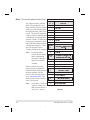
Table of Contents
Introduction
Scope . . . . . . . . . . . . . . . . . . . . . . . . . . . . . . . . 1-1
Model Designation . . . . . . . . . . . . . . . . . . . . . . . . . 1-1
System Overview . . . . . . . . . . . . . . . . . . . . . . . . . . 1-1
Communication Capabilities . . . . . . . . . . . . . . . . . . 1-2
Thermal Transfer Printer Internal Functions . . . . . . . . . . 1-2
Print Mechanism Capabilities . . . . . . . . . . . . . . . . . . 1-2
Media Transport Mechanism Capabilities . . . . . . . . . . . 1-2
Additional System Requirements . . . . . . . . . . . . . . . . . . 1-3
Media and Ribbon Requirements . . . . . . . . . . . . . . . . . . 1-3
Warnings and Precautions . . . . . . . . . . . . . . . . . . . . . . 1-4
Installation. . . . . . . . . . . . . . . . . . . . . . . . . . . . 1-4
230 VAC Operation . . . . . . . . . . . . . . . . . . . . . . . 1-4
Use of Shielded Cable. . . . . . . . . . . . . . . . . . . . . . 1-4
Ribbons and Printhead Wear . . . . . . . . . . . . . . . . . . 1-5
Repacking . . . . . . . . . . . . . . . . . . . . . . . . . . . . 1-5
Printer Specifications . . . . . . . . . . . . . . . . . . . . . . . . 1-6
Printing Considerations . . . . . . . . . . . . . . . . . . . . . 1-6
Print Speeds . . . . . . . . . . . . . . . . . . . . . . . . . . . 1-6
Media Handling . . . . . . . . . . . . . . . . . . . . . . . . . 1-6
Media . . . . . . . . . . . . . . . . . . . . . . . . . . . . . . 1-7
Ribbon. . . . . . . . . . . . . . . . . . . . . . . . . . . . . . 1-8
Zebra Programming Language II (ZPL II®) . . . . . . . . . . 1-8
Bar Codes . . . . . . . . . . . . . . . . . . . . . . . . . . . . 1-8
Standard Fonts . . . . . . . . . . . . . . . . . . . . . . . . . 1-9
Standard Printer Font Example . . . . . . . . . . . . . . . . 1-12
Physical . . . . . . . . . . . . . . . . . . . . . . . . . . . . 1-12
Zebra S-Series User’s Guide
i
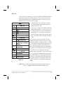
3
Electrical . . . . . . . . . .
Communications Interface .
Environmental Ranges . . .
Options and Accessories . .
.
.
.
.
.
.
.
.
.
.
.
.
.
.
.
.
.
.
.
.
.
.
.
.
.
.
.
.
.
.
.
.
.
.
.
.
.
.
.
.
.
.
.
.
.
.
.
.
.
.
.
.
.
.
.
.
.
.
.
.
.
.
.
.
.
.
.
.
.
.
.
.
1-12
1-13
1-13
1-13
Installation
Unpacking . . . . . . . . . . . . . . . . . . . . . . . . . . . . . . 2-1
Inspection . . . . . . . . . . . . . . . . . . . . . . . . . . . . . . 2-1
Reporting Damage. . . . . . . . . . . . . . . . . . . . . . . . . . 2-1
Storage and Reshipping . . . . . . . . . . . . . . . . . . . . . . . 2-1
Power Connection . . . . . . . . . . . . . . . . . . . . . . . . . . 2-2
AC Voltage Selection Procedure . . . . . . . . . . . . . . . . 2-2
AC Power Fuse Replacement . . . . . . . . . . . . . . . . . . 2-3
115 VAC Operation . . . . . . . . . . . . . . . . . . . . . . . 2-3
230 VAC Operation . . . . . . . . . . . . . . . . . . . . . . . 2-3
Site Requirements . . . . . . . . . . . . . . . . . . . . . . . . . . 2-4
Ribbon Loading (105Se) . . . . . . . . . . . . . . . . . . . . . . 2-4
Ribbon Loading (160S) . . . . . . . . . . . . . . . . . . . . . . . 2-7
Media Loading. . . . . . . . . . . . . . . . . . . . . . . . . . . . 2-8
Roll Media . . . . . . . . . . . . . . . . . . . . . . . . . . . 2-8
Tear-Off Mode . . . . . . . . . . . . . . . . . . . . . . . . . 2-10
Rewind Mode . . . . . . . . . . . . . . . . . . . . . . . . . 2-10
Peel-Off Mode . . . . . . . . . . . . . . . . . . . . . . . . . 2-10
Cutter Mode . . . . . . . . . . . . . . . . . . . . . . . . . . 2-11
Fanfold Media . . . . . . . . . . . . . . . . . . . . . . . . . 2-11
Removing Used Ribbon (105Se). . . . . . . . . . . . . . . . . . 2-12
Removing Used Ribbon (160S) . . . . . . . . . . . . . . . . . . 2-13
Initial Printer Power Up . . . . . . . . . . . . . . . . . . . . . . 2-14
ii
Zebra S-Series User’s Guide
4
Operation
Operating Your Zebra S-Series Printer Printer . . . . . . . . . . . 3-1
Printer Operating Modes . . . . . . . . . . . . . . . . . . . . . . 3-1
Media Sensing Modes. . . . . . . . . . . . . . . . . . . . . . 3-1
Transmissive Sensing Mode . . . . . . . . . . . . . . . . . . 3-2
Black-Mark Sensing Mode . . . . . . . . . . . . . . . . . . . 3-2
Media Transport Modes. . . . . . . . . . . . . . . . . . . . . 3-2
Tear-Off Mode . . . . . . . . . . . . . . . . . . . . . . . . . 3-2
Peel-Off Mode . . . . . . . . . . . . . . . . . . . . . . . . . 3-3
Rewind Mode . . . . . . . . . . . . . . . . . . . . . . . . . . 3-3
Cutter Mode . . . . . . . . . . . . . . . . . . . . . . . . . . . 3-3
Front Panel Keys . . . . . . . . . . . . . . . . . . . . . . . . . . 3-4
PAUSE Key . . . . . . . . . . . . . . . . . . . . . . . . . . . 3-4
FEED Key. . . . . . . . . . . . . . . . . . . . . . . . . . . . 3-4
CANCEL Key. . . . . . . . . . . . . . . . . . . . . . . . . . 3-4
MODE Key . . . . . . . . . . . . . . . . . . . . . . . . . . . 3-5
Front Panel Lights . . . . . . . . . . . . . . . . . . . . . . . . . . 3-5
Power On Self Test . . . . . . . . . . . . . . . . . . . . . . . . . 3-7
Printer Self Tests . . . . . . . . . . . . . . . . . . . . . . . . . . 3-7
Introduction . . . . . . . . . . . . . . . . . . . . . . . . . . . 3-7
CANCEL Key Self Test. . . . . . . . . . . . . . . . . . . . . 3-9
PAUSE Key Self Test . . . . . . . . . . . . . . . . . . . . . 3-10
FEED Key Test . . . . . . . . . . . . . . . . . . . . . . . . 3-11
FEED Key and PAUSE Key Test . . . . . . . . . . . . . . . 3-12
MODE Key Test . . . . . . . . . . . . . . . . . . . . . . . . 3-12
PAUSE Key and CANCEL Key Test . . . . . . . . . . . . . 3-12
FEED Key and CANCEL Key Test . . . . . . . . . . . . . . 3-13
Extended Printer Diagnostics . . . . . . . . . . . . . . . . . . . 3-13
Zebra S-Series User’s Guide
iii
5
Sample ZPL II Label Formats . . . . . . . . . . . . . . .
Format 1: Simple Text and a Barcode . . . . . . . . .
Format 2: Saving a Label Format As a Graphic Image
Format 3: Using a Serialized Data Field. . . . . . . .
.
.
.
.
.
.
.
.
.
.
.
.
.
.
.
.
3-14
3-15
3-15
3-16
Configuration and Calibration
Option Switches . . . . . . . . . . . . . . . . . .
Bank 1 (For Serial-Interface Printers Only) . . . .
Bank 2 . . . . . . . . . . . . . . . . . . . . .
Configuration Mode . . . . . . . . . . . . . . . .
Calibration. . . . . . . . . . . . . . . . . . .
Adjusting the Print Darkness . . . . . . . . .
Adjusting the Media Rest Position . . . . . .
Adjusting the Position of the Top of the Label
.
.
.
.
.
.
.
.
.
.
.
.
.
.
.
.
.
.
.
.
.
.
.
.
.
.
.
.
.
.
.
.
.
.
.
.
.
.
.
.
.
.
.
.
.
.
.
.
.
.
.
.
.
.
.
.
.
.
.
.
.
.
.
.
.
.
.
.
.
.
.
.
4-1
4-2
4-3
4-4
4-4
4-6
4-6
4-6
.
.
.
.
.
.
.
.
.
.
.
.
.
.
.
.
.
.
.
.
.
.
.
.
.
.
.
.
.
.
.
.
.
.
.
.
.
.
.
.
.
.
.
.
.
.
.
.
.
.
.
.
.
.
.
.
.
.
.
.
.
.
.
.
.
.
.
.
.
.
.
.
.
.
.
.
.
.
.
.
.
.
.
.
.
.
.
.
.
.
.
.
.
.
.
.
.
.
.
.
.
.
.
.
.
.
.
.
.
.
.
.
.
.
.
.
.
5-1
5-1
5-1
5-1
5-2
5-2
5-3
5-3
5-4
5-4
5-5
5-5
5-6
Interconnections
System Components . . . . . . . . . . . .
System Considerations . . . . . . . . . .
Communications Code . . . . . . . .
Interfaces . . . . . . . . . . . . . . .
Data Specifications . . . . . . . . . .
RS-232 Serial Data Port . . . . . . . . . .
Hardware Control Signal Descriptions
RS-232 Cabling Requirements . . . .
Interconnect to DTE Devices . . . . .
Interconnect to DCE Devices . . . . .
Parallel Cabling Requirements . . . .
Parallel Interface . . . . . . . . . . .
Signal Descriptions . . . . . . . . . .
iv
.
.
.
.
.
.
.
.
.
.
.
.
.
.
.
.
.
.
.
.
.
.
.
.
.
.
.
.
.
.
.
.
.
.
.
.
.
.
.
.
.
.
.
.
.
.
.
.
.
.
.
.
Zebra S-Series User’s Guide
6
Preventive Maintenance
Overview . . . . . . . . . . . . . . . . . . . . .
Cleaning . . . . . . . . . . . . . . . . . . . . . .
Exterior Surfaces . . . . . . . . . . . . . . .
Interior. . . . . . . . . . . . . . . . . . . . .
Printhead and Platen Roller . . . . . . . . . .
Media, Ribbon, and Label Available Sensors.
Cutter Module . . . . . . . . . . . . . . . . .
Lubrication . . . . . . . . . . . . . . . . . .
.
.
.
.
.
.
.
.
.
.
.
.
.
.
.
.
.
.
.
.
.
.
.
.
.
.
.
.
.
.
.
.
.
.
.
.
.
.
.
.
.
.
.
.
.
.
.
.
.
.
.
.
.
.
.
.
.
.
.
.
.
.
.
.
.
.
.
.
.
.
.
.
6-1
6-1
6-1
6-1
6-2
6-3
6-3
6-4
.
.
.
.
.
.
.
.
.
.
.
.
.
.
.
.
.
.
.
.
.
.
.
.
.
.
.
.
.
.
.
.
.
.
.
.
.
.
.
.
.
.
.
.
.
.
.
.
.
.
.
.
.
.
.
.
.
.
.
.
.
.
.
7-1
7-1
7-2
7-2
7-3
7-4
7-5
Adjustments
Toggle Positioning . . . . . . . . . . . . . . . .
Printhead Pressure Adjustment . . . . . . . . . .
Black-Mark Media Sensor Position Adjustment .
Transmissive Media Sensor Position Adjustment.
Upper Media Sensor . . . . . . . . . . . . .
Lower Media Sensor . . . . . . . . . . . . .
Media and Ribbon Sensor Sensitivity Adjustment
Troubleshooting
Troubleshooting . . . . . . . . . . . . . . . . . . . . . . . . . . . 8-1
Options
Peel-Off . . . . . . . . . . . .
Cutter Module . . . . . . . . .
Media Rewind . . . . . . . . .
Fanfold Supply Bin . . . . . .
ZebraNet (Ethernet) Interface .
Zebra S-Series User’s Guide
.
.
.
.
.
.
.
.
.
.
.
.
.
.
.
.
.
.
.
.
.
.
.
.
.
.
.
.
.
.
.
.
.
.
.
.
.
.
.
.
.
.
.
.
.
.
.
.
.
.
.
.
.
.
.
.
.
.
.
.
.
.
.
.
.
.
.
.
.
.
.
.
.
.
.
.
.
.
.
.
.
.
.
.
.
.
.
.
.
.
.
.
.
.
.
9-1
9-1
9-1
9-2
9-2
v
7
Black-Mark (Reflective) Sensor (105Se Only) . . . .
Optional Printer Fonts . . . . . . . . . . . . . . . . .
230 VAC Factory Setup . . . . . . . . . . . . . . . .
Memory Option . . . . . . . . . . . . . . . . . . . .
12-Dot/mm and 6-Dot/mm Printheads (105Se Only) .
.
.
.
.
.
.
.
.
.
.
.
.
.
.
.
.
.
.
.
.
.
.
.
.
.
.
.
.
.
.
.
.
.
.
.
9-2
9-3
9-3
9-4
9-4
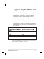
Appendix A
230 VAC Power Cord. . . . . . . . . . . . . . . . . . . . . . . . A-1
Appendix B
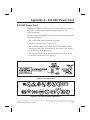
ASCII Code Chart. . . . . . . . . . . . . . . . . . . . . . . . . . B-1
Appendix C
Adjusting Bar Code Darkness. . . . . . . . . . . . . . . . . . . . C-1
Appendix D
Optional Printer Fonts . . . . . . . . . . . . . . . . . . . . . . . D-1
Glossary
Index
vi
Zebra S-Series User’s Guide
8
Introduction
Scope
This user’s guide contains descriptive information and operational instructions for the Zebra 105Se and 160S thermal transfer demand printers.
It contains information on how to set up and operate the printer as well
as adjustment and maintenance procedures that can be performed by the
operator. Information covering the use and operation of Zebra S-Series
Printer options is also included.
Additional documentation for the Zebra S-Series Printer is available:
• The ZPL II® Programming Guide (part # 46469L).
• The two-volume Maintenance Manual: Volume 1: General Maintenance (part # 38452L) contains the information you will need to
maintain your printer. Volume 2: Circuit Descriptions and Electrical
Schematics (part # 38453L) contains the information you will need to
repair the circuit boards at the component level. You may order both
volumes as a set by ordering part # 31452L.
Model Designation
Labels located inside the media compartment above the frame support
at the rear of the S-Series Printer include both the serial number and
model designation. If you need to contact our technical support
staff for assistance, please have both the model designation and serial
number available so that we may help you more efficiently.
System Overview
The S-Series Printer, when connected to an appropriate ASCII data
source, functions as a complete label, ticket, and tag printing system.
Customer-supplied asynchronous modems may be used to connect remote hosts to the S-Series Printer.
Connection of the S-Series Printer to data sources using data codes
other than ASCII requires the use of an appropriate protocol converter.
Connection to data sources using interfaces other than the type installed
in the printer requires the use of an appropriate interface converter.
Zebra S-Series User’s Guide
1-1
9
Communication Capabilities
The S-Series Printer comes with either an Electronics Industries Association (EIA) RS-232 serial data interface or a factory-installed parallel
interface. In both cases, the required interface cable is not supplied
with the printer.
Thermal Transfer Printer Internal Functions
Command/control data signals are received via the RS-232 port, parallel
port, or DIP switches and are sent to the main logic board. The microprocessor continuously monitors these signals along with the inputs received from the control panel and various sensors. The microprocessor
interprets this information and controls the S-Series Printer mechanics, printhead, communications, command interpretation, label formatting, media control, and mechanical drive.
Print Mechanism Capabilities
The print mechanism has been designed to print random information labels, tickets, and tags. It uses a thermal printhead that heats a ribbon as it
passes beneath the print elements, melting its ink onto the media (direct
thermal uses heat-sensitive media instead of an inked ribbon). Constant
print speeds may be selected via software control.
The standard printhead for the S-Series Printer has a print resolution of
8 dots/mm (203.2 dots/inch). Optional printheads are available for the
105Se for either 6 dots/mm (152 dots/inch) or 12 dots/mm (300 dots/inch)
resolution.
Media Transport Mechanism Capabilities
The media transport mechanism of the S-Series Printer has been designed to accommodate various types of media, including die-cut labels,
ticket and tag stock, continuous roll, and fanfold media.
Media may be rewound internally onto standard three-inch cores if the
Rewind Spindle option is installed. With the Peel-off option, backing
material may be rewound internally.
Ribbons for the S-Series Printer are supplied on one-inch cores in standard widths and lengths.
1-2
Zebra S-Series User’s Guide
10
Additional System Requirements
In addition to the Zebra S-Series Printer, you will need the following
items to form a complete label preparation system:
• Label, ticket, or tag stock
• An intelligent device, such as a computer, for data entry or entry of
ZPL II formats
• A data communication cable to connect the controlling device to the
printer (remote installations may require additional cables and communication devices, such as modems and/or protocol converters)
• Thermal transfer ribbon (if using thermal transfer mode)
Media and Ribbon Requirements
Print quality not only depends on the Zebra S-Series Printer, but also
on the print media. Factors such as reflectivity and contrast are important for bar code scanning applications. Factors such as paper abrasion
and temperature requirements are important in maintaining the life of the
printhead.
We STRONGLY RECOMMEND the use of Zebra-brand media for
continuous high quality printing. A wide range of paper, polypropylene, polyester, and vinyl stock has been specifically engineered to enhance the printing capabilities of the printer and to ensure against
premature printhead wear.
Zebra S-Series User’s Guide
1-3
11
Continuous roll form paper, fanfold media, or cardstock with optional
perforations and registration holes may be used. The standard 160S
Printer and 105Se Printer with an optional reflective sensor can use
“black-mark media” (media having a black mark printed on the liner
side for use in positioning the labels).
Since print quality is affected by media and ribbon, printing speeds, and
printer operating modes, it is very important to run tests for your applications. This is especially true if you’re operating in Peel-Off mode, where
these variables combine with label size, backing content, diecut depth,
and even humidity to affect printer operation.
Warnings and Precautions
Installation
CAUTION: To ensure that the Zebra S-Series Printer has proper cooling, do not place any padding or cushioning material on the back of, or
underneath, the unit.
230 VAC Operation
CAUTION: Refer to “Installation” for instructions on configuring your
printer for 230 VAC operation before connecting to a 230 VAC power
source.
Use of Shielded Cable
CAUTION: Refer to the “Interconnections” Section.
Zebra printers comply with FCC “Rules and Regulations”, Part 15, Subpart J, for Class A Equipment, using fully shielded data cables. Use of
unshielded cables may increase radiated emissions above the Class A
limits and is not recommended.
Zebra printers comply with international regulations governing radiated
emissions when using fully shielded data cables. Use of unshielded
cables may increase radiated emissions above the regulated limits.
1-4
Zebra S-Series User’s Guide
12
Ribbons and Printhead Wear
CAUTION: Ribbons used in the Zebra Technologies Corporation
Printer MUST be as wide as or wider than the media. Zebra-brand ribbons provide an extremely smooth backing surface that protects the printhead
from abrasion by the media. If the ribbon is narrower than the media, areas of
the printhead will be unprotected and subject to premature wear.
Repacking
CAUTION: If shipment of your printer is necessary, carefully pack the
printer in a suitable container to avoid damage during transit. Whenever
possible, use the original container from the factory. If the original container is not available, an optional packing kit can be purchased from
Zebra. When using a different container, a procedure similar to the original
factory packaging should be followed.
Refer to “Installation” for further repacking instructions.
Zebra S-Series User’s Guide
1-5
13
Printer Specifications
Printing Considerations
Specification
105Se
160S
Resolution (thermal transfer
203 dots per inch
Optional
Optional
203 dots per
or direct thermal)
(8 dots per mm)
152 dots per inch
300 dots per inch
inch (8 dots
(6 dots per mm)
(12 dots per mm)
per mm)
0.00492"
0.00656"
0.0033" x 0.0039"
0.00492"
(0.125 mm)
(0.167 mm)
(0.084 x 0.100 mm) (0.125 mm)
4.09"
4.09"
4.09"
(104 mm)
(104 mm)
(104 mm)
(160 mm)
Standard
15"
26"
18"
9.5"
Maximum
memory
(381 mm)
(660 mm)
(457 mm)
(241 mm)
print length
With 512 KB
39"
39"
N/A
25"
Dot size
Maximum print width
addl memory (991 mm)
Bar code modulus
5 mil to 50 mil
(991 mm)
6.6 mil to 66 mil
(X) dimension
6.30"
(635 mm)
3.33 mil to 33.3 mil 5 mil to
50 mil
Thin film printhead with Energy Control
Print Speeds
Programmable constant printing speeds of 2" (51 mm), 3" (76 mm),
4" (102 mm), 5" (127 mm), and 6" (152 mm) per second.
The 105Se with optional 300 dots/inch resolution supports programmable constant printing speeds of 2.4" (61 mm), 3" (76 mm), and
4" (102 mm) per second.
Media Handling
• Tear-off mode: Produced in strips.
• Peel-off mode: Requires Peel-Off option or Media Rewind option.
Labels are dispensed and peeled from the liner, and the liner is rewound internally.
• Rewind mode: Requires Media Rewind option. A full roll of printed
labels is rewound internally.
• Cutter mode: Requires Cutter Module option. Media cut after printing; under software control.
1-6
Zebra S-Series User’s Guide
14
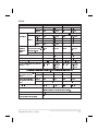
Media
Media Specifications
Total media width
105Se
160S
Maximum
4.5"
114.3 mm
7.2"
182.9 mm
Minimum
0.75"
19.05 mm
2.0"
50.8 mm
Maximum
Refer to Printing Considerations on page 1-6.
Tear-Off
0.63"
16.00 mm
0.63"
16.00 mm
Peel-Off
0.50"
12.8 mm
0.50"
12.8 mm
Rewind
0.50"
12.8 mm
0.50"
12.8 mm
Cutter
1.25"
31.75 mm
N/A
N/A
0.381 mm
0.015"
0.381 mm
0.0023"
0.0584 mm
0.0023"
0.0584 mm
Core size
3.0"
76.2 mm
3.0"
76.2 mm
Maximum roll diameter
8.0"
203.2 mm
8.0"
203.2 mm
Label length
Minimum
Total
Maximum (Printhead po-
thickness
sition may need to be ad- 0.015"
(includes
justed above 0.01")
liner)
Minimum
Interlabel gap (0.115"/3 mm preferred) 0.079" - 0.157"
2 mm - 4 mm 0.079"- 0.157" 2 mm -4 mm
Maximum internal fanfold media pack
8.0" x 7.2" x
203.2 mm x
8.0" x 7.2" x
203.2 mm x
size (L x W x H)
6.2"
182.8 mm x
6.2"
182.8 mm x
157.4 mm
157.4 mm
Additional Specifications for Black-Mark Media (optional on 105Se)
Mark thickness (measuring parallel to label/tag
edge)
Mark width (measuring
perpendicular to label/tag
edge)
Minimum
0.12"
3 mm
0.12"
3 mm
Maximum
0.43"
11 mm
0.43"
11 mm
Minimum
0.43"
11 mm
0.43"
11 mm
Maximum
Full media width.
Mark-to-mark registration tolerance
+ /- 0.016"
Mark location
Mark
must
Full media width.
+/- 0.4 mm
+/- 0.016"
+/- 0.4 mm
be located on the inside of the media (closest to the
printers mainframe when loaded in the printer).
Mark density
> 1.0 ODU (Optical Density Unit)
Density of the back of the media on
0.5 ODU maximum
which the black mark is printed
Zebra S-Series User’s Guide
1-7
15
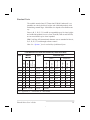
Ribbon
Ribbon Width
Zebra recommends using ribbon at least as
4.33"
110 mm
6.89"
175 mm
Minimum
0.94"
24 mm
2.0"
51 mm
2:1 media to ribbon roll ratio
984 ft
300 m
984 ft
300 m
3:1 media to ribbon roll ratio
1476 ft
450 m
1476 ft
450 m
Inner diameter of core
1.0"
25.4 mm
1.0"
25.4 mm
Outside diameter of full roll of ribbon
3.2"
81 mm
3.2"
81 mm
the printhead from wear.
Lengths
Roll size
160S
Maximum
wide as the media you are using to protect
Standard
105Se
Zebra Programming Language II (ZPL II®)
n
Downloadable graphics with data
compression
n
Communicates in printable ASCII
characters
n
Bit image data transfer and printing,
including mixing of text and graphics
n
Controlled by a mainframe, minicomputer,
PC, or other data entry device
n
Format inversion
n Mirror image printing
n Four-position field rotation
(0°, 90°, 180°, 270°)
n
n
n
Serialized fields
In-Spec OCR-A and OCR-B
n UPC/EAN [nominal 100% magnification
(6 dots/mm and 12 dots/mm only)]
n
Bitmap and scalable fonts
Programmable quantity with print pause
Bar Codes
n
Code 11, Code 49, Code 93
n Code 39 (Supports ratios of 2:1, 3:1, 5:2,
7:3)
n
Code 128 (Supports serialization in
subsets B and C and UCC Case C Codes)
n
CODABAR (Supports ratios of 2:1, 3:1,
and 5:2)
n
Industrial 2 of 5, Standard 2 of 5
n Plessey
n MAXICODE
n
UPC-A
PDF 417
n POSTNET
n MSI
n E/EAN-8, E/EAN-13, EAN
EXTENSIONS
n
n
Interleaved 2 of 5
3 of 9
n Data Matrix
n
1-8
Zebra S-Series User’s Guide
16
Standard Fonts
The scalable smooth font (CG Triumvirate™ Bold Condensed) is expandable on a dot-by-dot basis, height- and width-independent, while
maintaining smooth edges. Maximum size depends on available memory.
Fonts A, B, C, D, E, F, G, and H are expandable up to 10 times, heightand width-independent; however, fonts E and H (OCR-A and OCR-B)
are not considered in-spec when expanded.
IBM Code Page 850 international character sets are standard in fonts A,
B, C, D, E, F, G, and through software control.
Note: See “Options” for the availability of additional fonts.
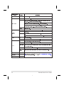
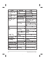
Font Matrices for 8 dots/mm Printhead (105Se and 160S)
Font
Matrix
Type*
Character Size
(in dots)
Width
Intercharacter
gap
Height
Width
Char./inch
Height
Width
Char./mm
Millimeters
Height
Inches
A
9
5
1
U-L-D
0.044
0.029
33.90
1.13
0.75
1.33
B
11
7
2
U
0.054
0.044
22.60
1.38
1.13
0.89
C, D
18
10
2
U-L-D
0.088
0.059
16.95
2.25
1.50
0.67
E
28
15
5
OCR-B
0.138
0.098
10.17
3.50
2.50
0.40
F
26
13
3
U-L-D
0.128
0.079
12.71
3.25
2.00
0.50
G
60
40
8
U-L-D
0.295
0.236
4.24
7.50
6.00
0.17
H
21
13
6
OCR-A
0.103
0.093
10.71
2.63
2.38
0.42
GS
24
24
0
SYMBOL
0.118
0.118
8.48
3.00
3.00
0.33
0
Default: 15 x 12
U-L-D
Scalable
* U = Uppercase, L = Lowercase, D = Descenders
Zebra S-Series User’s Guide
1-9
17
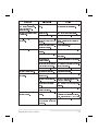
Font Matrices for 6 dots/mm Printhead
Font
Type*
Matrix
Character Size
(in dots)
Intercharacter
gap
Height
Width
Char./inch
Width
Char./mm
A
9
5
1
U-L-D
0.059
0.039
25.40
1.50
1.00
1.00
B
11
7
2
U
0.072
0.059
16.93
1.83
1.50
0.67
C, D
18
10
2
U-L-D
0.118
0.079
12.70
3.00
2.00
0.50
E
21
10
3
OCR-B
0.138
0.085
11.72
3.50
2.17
0.46
F
26
13
3
U-L-D
0.171
0.105
9.53
4.33
2.67
0.38
G
60
40
8
U-L-D
0.394
0.315
3.18
10.00
8.00
0.13
H
17
11
4
OCR-A
0.112
0.098
10.16
2.83
2.50
0.40
GS
24
24
0
SYMBOL
0.157
0.157
6.35
4.00
4.00
0.25
0
Default: 15 x 12
U-L-D
Height
Width
Millimeters
Height
Inches
Scalable
* U = Uppercase, L = Lowercase, D = Descenders
1-10
Zebra S-Series User’s Guide
18
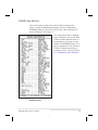
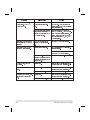
Font Matrices for 12 dots/mm Printhead
Font
Type*
Matrix
Character Size
(in dots)
Intercharacter
gap
Height
Width
Char./inch
Height
Width
A
9
5
1
U-L-D
0.029
0.016
50.80
0.73
0.40
2.00
B
11
7
2
U
0.036
0.023
33.86
0.91
0.58
1.34
C, D
18
10
2
U-L-D
0.059
0.033
25.40
1.49
0.83
1.00
E
42
20
6
OCR-B
0.138
0.066
23.44
3.50
1.67
0.92
F
26
13
3
U-L-D
0.185
0.042
19.06
2.15
1.06
0.76
G
60
40
8
U-L-D
0.198
0.132
6.36
5.02
3.35
0.26
H
34
22
8
OCR-A
0.112
0.072
20.32
2.84
1.82
0.80
GS
24
24
0
SYMBOL
0.079
0.079
12.70
2.00
2.00
0.50
0
Default: 15 x 10
U-L-D
Char./mm
Width
Millimeters
Height
Inches
Scalable
* U = Uppercase, L = Lowercase, D = Descenders
Zebra S-Series User’s Guide
1-11
19
Standard Printer Font Example
Physical
Physical Characteristics
105Se
160S
Height
15.4"
391 mm
15.4"
391 mm
Width
10.5"
267 mm
13.1"
333 mm
Length
18.9"
480 mm
18.9"
480 mm
43 lbs.
19.5 kg
55 lbs.
24.9 kg
Weight (without options)
Electrical
• 115 VAC +15%/-20% or 230 VAC +15%/-15%; 48-62 Hz
• 5 Amps @ 115V, 3 Amps @ 230V
• UL 1950 Listed-Certified to CAN/CSA-C22.2 No. 950- M89;
classified to IEC 950; complies with FCC and Canadian DOC
class “A” rules
• Carries the CE mark of compliance.
1-12
Zebra S-Series User’s Guide
20
Communications Interface
• RS-232 at 110 to 19,200 baud (select from standard rates). Baud
rate, data bits, parity, error detection protocol, and XON-XOFF or
DTR/DSR handshaking are all switch-selectable. Stop bits are fixed
at 1
• Compatibility Mode Parallel Interface. Maximum cable length: 10 ft.
(304.8 cm)
Environmental Ranges
Operating temperature
+41°F to +104°F
+5°C to +40°C
Storage temperature
-40°F to +158°F
−40°C to +70°C
Non-condensing relative
humidity
Operating
20% to 85%
Storage
20% to 85%
Options and Accessories
• Peel-Off capability only*
• Cutter Module
• Cutter Catch Tray
• Media Rewind with rewind and peel-off capabilities*
• Fanfold Supply Bin
• ZebraNet™
• Black-Mark (Reflective) Sensor (105Se only)
• Scalable and bit-mapped smooth fonts
• Additional 512 KB memory (not available for 105Se [300 dots/inch])
* Peel Off and Media Rewind options are mutually exclusive of the
Cutter option.
Zebra S-Series User’s Guide
1-13
21
22
Installation
Unpacking
When unpacking the Zebra S-Series Printer, make sure you save all
packing materials. Once the printer is out of the box, raise the printer’s
Media Access Door and remove the power cord.
Inspection
Inspect the printer for possible damage incurred during shipment.
• Check all exterior surfaces for damage.
• Raise the Media Access Door and inspect compartment for damage
to components.
Reporting Damage
If you discover shipping damage upon inspection:
• Immediately notify the shipping company of the damage.
• Retain all packaging material for shipping company inspection.
• File a damage report with the shipping company and notify your local distributor and Zebra Technologies Corporation of the damage.
Zebra Technologies Corporation is not responsible for any damage
incurred during shipment of the equipment and will not repair this
damage under warranty. Immediate notification of damage to the
shipping company or its insuring agency will generally result in ensuring any damage claim validity and ultimate monetary compensation.
Storage and Reshipping
If you are not placing the printer into operation immediately, repackage
it using the original packing materials. The S-Series Printer may be
stored under the following conditions:
Zebra S-Series User’s Guide
2-1
23
• Temperature: -40° to +158° F (-40° to +70° C)
• Relative humidity: 20% to 85% non-condensing
Should it become necessary to ship your printer, remove any ribbon
and paper roll from the supply spools, otherwise damage to the printer
could result. Carefully pack the printer in a suitable container to avoid
damage during transit. Whenever possible, use the original container
and packaging material from the factory. If you use a different container, a procedure similar to the original factory packaging should be
followed.
CAUTION: Do not package the printer in a rigid container without utilizing shock mounts or shock-absorbing packing material. A rigid container will allow shock on the outside to be transmitted undamped to
the unit, which may cause damage.
Power Connection
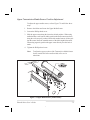
AC Voltage Selection Procedure
The S-Series Printer’s AC voltage may be set for either 115 VAC or
230 VAC operation. To match the printer’s power entry selection to the
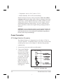
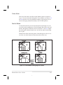
available power source, refer to Figure 2.1 and follow the procedure
outlined below:
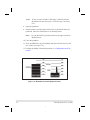
1. Locate the AC power area at the rear of the printer.
2. Using a small flatblade
screwdriver or similar
tool, move the Voltage
Selection switch to the
115 V or 230 V position
as required. (The initial
position of the switch
depends on how the
printer was ordered.)
Make sure that the appropriate fuse is in place.
See Figure 2.1.
Figure 2.1 AC Power Area
2-2
Zebra S-Series User’s Guide
24
AC Power Fuse Replacement
A user-replaceable AC Power Fuse is located just above the Power
ON/OFF Switch (see Figure 2.1). For a 115 VAC installation, the replacement fuse is a 3AG Fast Blow style rated at 5 Amp/250VAC. For a
230 VAC installation, the fuse is the same style but rated at 3 Amp/250
VAC. Make sure the fuse you use is correct for the voltage source.
Before replacing the fuse, turn the AC Power Switch OFF and unplug
the AC Power Cable.
To replace the fuse, insert the tip of a flatblade screwdriver into the slot
in the end of the Fuse Holder End Cap. Press in slightly on the End
Cap and turn the screwdriver slightly counterclockwise. This will disengage the End Cap from the Fuse Holder and allow you to remove the
fuse. To install a new fuse, reverse the procedure.
115 VAC Operation
1. Confirm that the voltage selector switch is set to 115 V.
2. Attach the supplied power cord to the AC power receptacle located on
the rear of the printer.
3. Connect the opposite end of the power cord to a properly grounded
source of 115 VAC (50 or 60 Hz) power rated for at least 5 Amps.
230 VAC Operation
1. Confirm that the voltage selector switch is set to 230 V.
2. Depending on how the printer was ordered, a power cord may or may
not be provided for 230 VAC operation. If not provided, obtain a cord
set with the proper AC Power plug. The cord may then be connected to
the standard (international) IEC-type 3-prong AC connector provided
on the S-Series Printer. Refer to “Appendix A” for more information.
Zebra S-Series User’s Guide
2-3
25
Site Requirements
CAUTION: To ensure that the S-Series Printer has proper ventilation
and cooling, do not place any padding or cushioning material on the
back of or underneath the unit because this will restrict the air flow.
The S-Series Printer may be installed on any solid, level surface of sufficient size and strength to accommodate the unit. The area in which the
printer will operate must meet the environmental conditions specified.
Since the Zebra S-Series Printer was designed and is fabricated as an
industrial-type unit, it will function satisfactorily in areas such as a warehouse or factory floor that conform to the specified environmental and
electrical conditions.
Ribbon Loading (105Se)
Refer to Figure 2.4 throughout this procedure.
Note:
When placing the ribbon roll on the Ribbon Supply Spindle,
make sure that the core is pushed up against the stop on the
ribbon supply spindle and that the ribbon is aligned squarely
with its core. If this is not done, the ribbon may not cover the
inside edge of the printhead, exposing print elements to
potentially damaging contact with the media.
Note:
Do not load ribbon if the printer is to be used in the Direct
Thermal Mode.
CAUTION: Do not use ribbon that is narrower than the media. If the
printhead is not protected by the smooth backing of the ribbon, excessive abrasion may cause premature printhead failure.
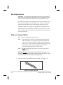
1. Align the segments of the Ribbon Supply Spindle. See Figure 2.2.
Figure 2.2 Spindle Alignment
2-4
Zebra S-Series User’s Guide
26
2. Place the Ribbon Roll on the Ribbon Supply Spindle.
3. Open the printhead by moving the handle to the OPEN position.
4. Important.....To make ribbon loading and unloading easier, make a
leader for your ribbon roll if it doesn’t already have one (refer to
Figure 2.3):
Tear off a strip of media (labels and backing) about 6 to 12 inches long from the roll.
Peel off a label from this strip. Remove the remaining labels. Apply half of this label
to the end of the strip and the other half to the end of the ribbon. This acts as a ribbon
leader.
5. Thread the leader and attached ribbon as shown in the illustration. Be careful not to crease or wrinkle the ribbon.
6. Remove the Hook from the Ribbon Take-Up Spindle.
7. Place the leader under the long leg of the Hook and wind for several turns.
8. Close the printhead by moving the lever to the CLOSED position.
Figure 2.3 Making a Leader
Zebra S-Series User’s Guide
2-5
27
Figure 2.4 Ribbon Loading Diagram
2-6
Zebra S-Series User’s Guide
28
Ribbon Loading (160S)
Refer to Figure 2.4 throughout this procedure.
Note:
When placing the ribbon roll on the Ribbon Supply Spindle,
make sure that the core is pushed up against the stop on the
ribbon supply spindle and that the ribbon is aligned squarely
with its core. If this is not done, the ribbon may not cover the
inside edge of the printhead, exposing print elements to
potentially damaging contact with the media.
Note:
Do not load ribbon if the printer is to be used in the Direct
Thermal Mode.
CAUTION: Do not use ribbon that is narrower than the media. If the printhead is not protected by the smooth backing of the ribbon, excessive abrasion may cause premature printhead failure.
1. Align the segments of the Ribbon Supply Spindle. See Figure 2.2.
2. Place the Ribbon Roll on the Ribbon Supply Spindle.
3. Open the printhead by moving the handle to the OPEN position.
4. Important.....To make ribbon loading and unloading easier, make a
leader for your ribbon roll if it doesn’t already have one (refer to
Figure 2.3):
Tear off a strip of media (labels and backing) about 6 to 12 inches long from the roll.
Peel off a label from this strip. Remove the remaining labels. Apply half of this label
to the end of the strip and the other half to the end of the ribbon. This acts as a ribbon
leader.
5. Thread the leader and attached ribbon as shown in the illustration. Be careful not to crease or wrinkle the ribbon.
6. Place the leader around the Ribbon Take-Up Spindle and wind counterclockwise for several turns.
7. Close the printhead by moving the lever to the CLOSED position.
Zebra S-Series User’s Guide
2-7
29
Media Loading
To load media, move the Printhead Locking Lever to the OPEN position. Refer to Figures 2.5, 2.6, 2.7, and 2.8. When the media is loaded,
close the printhead by moving the lever on the upper printhead
mechanism to the CLOSED position.
Note:
The first time you load media and whenever you subsequently
change the media type you must re-calibrate the printer. See
the Configuration and Calibration Section.
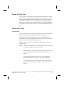
Roll Media
Roll media may contain labels of a fixed length with gaps in between or
it may be formed as one continuous length with no gaps (see Continuous Media in the Glossary). Both types of roll media mount inside the
printer in the same manner. To load roll media, refer to Figure 2.5
and/or 2.6 and do the following:
1. Move the Media Guide and Media Supply Guide as far away from the
printer frame as possible.
2. Place the media roll on the Media Supply Hanger.
3. Push the Media Supply Guide inward until it is just touching the outer
side of the Media Supply Roll. (The Guide must not cause pressure or
excessive drag on the Media Supply Roll.)
4. Thread the media through the printhead as shown in the illustrations.
5. Adjust the Media Guide until it just touches the outer edge of the media
without causing it to buckle.
6. Close the printhead by moving the lever located on the upper printhead
assembly to the CLOSED position.
2-8
Zebra S-Series User’s Guide
30
Figure 2.5 Roll Media Loading Diagrams
Figure 2.6 105Se Roll Media Loading (with Peel-Off)
Zebra S-Series User’s Guide
2-9
31
Tear-Off Mode
Follow the instructions described in Roll Media.
Rewind Mode
The Rewind Option must be installed in the printer. To initially configure the printer for this mode, follow these steps:
1. Remove the Media Rewind Plate from its storage location in front of
the printhead inside the media compartment.
2. Invert the Rewind Plate so that the lip on the attached Hook Plate points
down.
3. Insert the Hook Plate lip a short distance (1/2") into the lower opening
in the Side Plate.
4. Align the upper end of the Rewind Plate with the corresponding opening
in the Side Plate and slide the Rewind Plate in so that it stops against the
Main Frame.
5. Remove the Hook from the Take-Up Spindle Shaft.
6. Route the media as shown in Figures 2.5 and 2.6, wind it 1-2 times
around a 3" core.
Peel-Off Mode
After loading the media, follow these steps:
1. Remove the Rewind Plate if one is present and store it on the two
mounting screws on the inside of the front panel. Align the notch or
web in the media so that the Take Label Sensor can sense a peeled label.
2. Load media as shown in Figures 2.5 and 2.6.
3. Remove the Hook from the Take-Up Spindle Shaft.
4. Remove several labels from the media backing and then wind the backing 1-2 times around the Media Take-Up Spindle and reinstall the
Hook.
2-10
Zebra S-Series User’s Guide
32
Cutter Mode
Follow the instructions described in Roll Media with the exception of
step 6: first route the media through the Cutter Module (see Figures 2.5
and 2.6) and then close the printhead assembly by moving the lever located on the upper printhead assembly to the CLOSED position.
Fanfold Media
To load fanfold media, place the fanfold media in the bottom or to the
rear of the media compartment or Fanfold Supply Bin (105Se only) and
thread it through the printhead as shown in Figures 2.7 and 2.8. Adjust
the media guide using the thumb screw to keep the media from drifting
left or right.
Fanfold media from outside the printer feeds through one of the two access slots, one at the bottom of the printer and one at the rear.
Figure 2.7 Fanfold Media Loading Diagrams (105Se)
Zebra S-Series User’s Guide
2-11
33
Figure 2.8 Fanfold Media Loading Diagrams (160S)
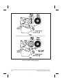
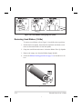
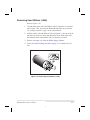
Removing Used Ribbon (105Se)
To remove used ribbon, refer to Figure 2.9 and follow the steps below.
1. Pull the hook out slightly, then rotate the hook back-and-forth several
times as shown and remove it from the spindle.
2. Grasp the used ribbon and remove it from the Ribbon Take-Up Spindle.
3. Remove the empty core from the Ribbon Supply Spindle.
4. Follow the Ribbon Loading procedure on page 2-4 to load the new ribbon.
Figure 2.9 Removing Used Ribbon (105Se)
2-12
Zebra S-Series User’s Guide
34
Removing Used Ribbon (160S)
Refer to Figure 2.10.
1. Turn the knob at the end of the Ribbon Take-Up Spindle (1) clockwise
until it stops. This will cause the Ribbon Release Bars to pivot down
(2), easing the spindle’s “grip” on the wound ribbon.
2. Slide the ribbon off of the Ribbon Take-Up Spindle. Once the used ribbon has been removed, ensure that the arrow on the knob aligns with
the indented notch in the Ribbon Take-Up Spindle (see inset).
3. Remove the empty core from the Ribbon Supply Spindle.
4. Follow the ribbon loading procedure on page 2-7 to load the new ribbon.
Figure 2.10 Removing Used Ribbon (160S)
Zebra S-Series User’s Guide
2-13
35
Initial Printer Power Up
After you finish loading the ribbon and media, continue reading through
“Operation” and “Configuration and Calibration.” Perform the following initial printer power-up steps as you come to them:
1. Power On Self Test (POST)
2. Calibration
Subsequent power-ups will not necessarily require step 2 to be performed. See “Operation” and “Configuration and Calibration” for further information.
2-14
Zebra S-Series User’s Guide
36
Operation
Operating Your Zebra S-Series Printer
Now that your printer is ready for operation, how does it work? The
Zebra S-Series Printer is designed to receive instructions from a host
computer, such as an IBM-compatible PC. To create a label, you will
either need to use label design software or write a format in ZPL II®,
which is a programming language for creating label formats. If you are
using label design software, refer to the instructions provided with your
software package to determine how to proceed.
If you are using, or plan to use, ZPL II, make sure you have a copy of
the ZPL II Programming Guide. This guide was available at the time
you ordered your printer, but if you do not have a copy then submit the
mail- or fax-in card in the front of this book to get a copy. For some
sample ZPL II label formats, refer to the information at the end of this
chapter. But first, we’ll describe the different operating modes.
Printer Operating Modes
The S-Series Printer can be configured for several different modes of
operation by sending the proper commands from the host computer.
Operating modes may also be configured via a bank of DIP switches at
the rear of the printer. (See “Configuration and Calibration” for more
information about DIP switches.)
Media Sensing Modes
There are two basic modes by which the printer can sense the position
of the media: Transmissive Sensing Mode and Black-Mark Sensing
Mode. The 160S comes standard with both Transmissive Sensing
Mode and Black-Mark Sensing Mode capabilities. The 105Se comes
standard with Transmissive Sensing Mode capability, but may be factory ordered with an additional Black Mark Sensor.
Zebra S-Series User’s Guide
3-1
37
Transmissive Sensing Mode
In Transmissive Sensing Mode, a sensor detects a light shining through
a web, notch, or hole in non-continuous media. In this way, the printer
determines the position of the label/tag.
Black-Mark Sensing Mode
In Black-Mark Sensing Mode, you use media having black marks
printed on the back of the label liner for each label. To determine the
label length and top of label, the printer’s Black Mark Sensor detects
the black mark similar to the way in which the Transmissive Sensor detects the notch or gap in the media.
Media Transport Modes
Tear-Off Mode
When the media is in the rest (idle) position, the webbing between labels is over theTear-Off/Peel-Off Bar. To print a label, the printer first
backfeeds the media until the start of the label is directly under the
printhead and then prints the entire label.
After a label is printed, the media feeds forward until the end of the label is past the Tear-Off/Peel-Off Bar. This label position is determined
by commands sent to the printer from the host computer or by front
panel adjustments.
When a quantity of labels is required, a format for printing a batch of
labels can be sent to the printer. Once a label is printed, the media will
feed forward to the start of the next label and printing will continue. In
this way, the printer will print the batch and stop when it reaches the
quantity required.
When a quantity of individual labels is required, the format for printing
a batch of labels can still be sent to the printer. The operator can use
the PAUSE Key to cycle the printing one label at a time. The operator
can then tear off each label before printing the next one.
3-2
Zebra S-Series User’s Guide
38
Peel-Off Mode
When the media is in the rest (idle) position, the start of the label to be
printed is slightly in front of the printhead. To print a label, the printer
first backfeeds the media until the start of the label is directly under the
printhead and then prints the entire label.
In this mode, once the label is printed, the media passes over the TearOff/Peel-Off Bar at an extremely sharp angle. The backing material is
peeled away from the label and winds around the Peel-Off Spindle or the Media Rewind Spindle. The media feeds forward until
most of the label hangs loose from the backing. The label is held
in this position by that portion of the backing that has not crossed
the Tear-Off/Peel-Off Bar.
The Label Available Sensor is located on the printer in a position where
it is activated by the label. When the operator removes the label, the
printer backfeeds the media either to the rest (idle) position or to the
printing position and prints the next label. When it is necessary to remove the media backing from the Take-Up Spindle, you do not need to
turn the printer OFF.
Rewind Mode
Some applications call for the media to be rewound onto a core as the
labels are printed.
When the media is in the rest (idle) position, the start of the next label is
directly under the printhead. After the label is printed, the media feeds
forward until the start of the next label is under the printhead. The media
never backfeeds in this mode.
When the printer completes a batch of labels, printing will stop.
Cutter Mode
In this mode the cutter, under software control, automatically cuts individual labels (or at the end of batches of labels) after printing. The optional Cutter Catch Tray gathers the completed labels.
Zebra S-Series User’s Guide
3-3
39
Front Panel Keys
PAUSE Key
The PAUSE key stops and restarts the
printing process. If the printer is idle
(not printing) when the PAUSE key is
pressed, no printing can occur. If the
PAUSE key is pressed while printing is
in progress, the printing stops once the
current label is complete. Pressing the
PAUSE key a second time resumes the
printing process.
FEED Key
The FEED key forces the printer to feed
one blank label. If the printer is idle, or
if the PAUSE function is active when
the FEED key is pressed, one blank label feeds from the printer immediately.
If the printer is printing, then one blank
label feeds out after completion of the
current batch of labels. After one blank
label feeds out, pressing FEED again
provides another blank label.
CANCEL Key
The CANCEL key is only recognized in
PAUSE mode. Press CANCEL to cancel the current label format. If no format is printing, then the next one to be
printed will be canceled. If no formats
are in memory, the CANCEL key is ignored. If the CANCEL key is pressed
for an extended period of time (3 seconds), the printer cancels all formats in
memory and the DATA light turns OFF.
3-4
Figure 3.1
Printer Front Panel
Zebra S-Series User’s Guide
40
MODE Key
The MODE key puts the printer in Configuration Mode. In this mode,
you can adjust the Print Darkness, Media Tear-Off Position, and Label
Top Position, or perform a Calibration. See “Configuration and Calibration.”
Front Panel Lights
Refer to Figure 3.1 for the location of the lights.
Note:
If an operating condition which causes a light to be ON
constantly and one which causes the same light to flash occur
simultaneously, the light flashes.
Zebra S-Series User’s Guide
3-5
41
Indicator Light
Name
POWER
Status
Indication
ON
Printer is ON.
OFF
Normal operation.
Head Over Temperature condition. Printing stops until the printhead
cools down. Printing resumes automatically.
PRINTHEAD
ON
Printhead Under Temperature condition. Printing continues.
Power Supply Over Temperature condition. Printing stops until the
power supply cools down. Printing resumes automatically.
PAPER/
RIBBON
Flashing
Printhead Open.
OFF
Media and ribbon (if used) are properly loaded.
ON
Paper out.
Flashing
1. In Thermal Transfer Mode: Ribbon is out.
2. In Direct Thermal Mode: Ribbon is in the printer.
PAUSE
OFF
Normal operation.
ON
Printer has stopped all printing operations.
OFF
Normal operation, no data being received.
ON
Labels are printing.
Single flash The
DATA
CANCEL key was pressed and a format was successfully deleted
from the print queue.
Flashing
Receiving data from host computer.
Slow
Printer sent a stop transmitting command to the host computer.
flashing
DARKEN
ON
POSITION
ON
CALIBRATE
ON
Printer is in the Configuration Mode. See Configuration and Calibration for more information.
3-6
Zebra S-Series User’s Guide
42
Power On Self Test
A Power On Self Test (POST) is performed each time the printer is turned
ON. This test checks for proper initialization of various electronic circuits
and establishes starting parameters as those stored in the printer’s memory.
During this test sequence, the front panel lights will turn ON and OFF to
ensure proper operation. At the end of this self test, only the POWER light
will remain lit. If other lights are also lit, refer to the Troubleshooting Section.
Printer Self Tests
Introduction
These self tests produce sample labels and provide specific information
that helps determine the operating conditions for the printer.
Each self test is enabled by holding in a specific Front Panel key or
combination of keys while turning the Power Switch ON. Keep the key
depressed until the Front Panel Lights turn ON.
When the Power On Self Test is completed, the selected self test automatically starts.
Notes:
When performing self tests, all data interface cables connected
to the rear of the printer must be removed.
When canceling a self test before its actual completion, always
turn the printer Power OFF and then back ON to reset the
printer.
When performing these self tests in the Peel-Off Mode, the
operator must remove the labels as they become available.
Unless specifically stated, all tests print in Tear-Off mode in
Tear-Off printers and in Peel-Off Mode for Peel and Rewind
printers.
Zebra S-Series User’s Guide
3-7
43
If your media is not wide enough, the test labels will only print
out to the edge of the label. If your media is too short, the test
label will continue printing on the next label.
Some of the printer self tests produce labels at varying print speeds.
These speeds may be referred to as “inches per second,” “millimeters
per second,” or by alphabetic letter designation (i.e., “A,” “B,” “C,”
etc.). The following chart shows the relationships between the different
speeds.
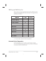
Letter
Designation
English
Metric
A*
2"/sec.
51 mm/sec.
B
3"/sec.
76 mm/sec.
C
4"/sec.
102 mm/sec.
5"/sec.
127 mm/sec.
D
6"/sec.
152 mm/sec.
* Speed “A” for the 105Se with the optional 300 dots-per-inch printhead is 2.4" (61 mm).
3-8
Zebra S-Series User’s Guide
44
CANCEL Key Self Test
This self test prints a single label which contains a listing of the
printer’s current configuration parameters stored in Configuration
(EEPROM) Memory. Press the CANCEL key while turning the AC
Power Switch ON. See Figure 3.2.
The configuration may be changed
either temporarily (for specific label
formats or ribbon and label stock), or
permanently (by saving the new parameters in EEPROM Memory). Saving new parameters occurs whenever
a Printer Calibration procedure is
performed. Refer to the procedure
in “Configuration and Calibration.”
Figure 3.2 CANCEL Key Test
Sample Printout
Zebra S-Series User’s Guide
3-9
45
PAUSE Key Self Test
This self test is actually comprised of four individual test features.
1. The initial self test prints 15 labels at speed “A” then automatically
PAUSES the printer. Each time the PAUSE key is pressed, an additional 15 labels print out.
2. While the printer is PAUSED, pressing the CANCEL key once alters the
self test. Now each time the PAUSE key is pressed the printer prints 15 labels at speed “D” (“C” for the 300 dpi 105Se).
3. While the printer is PAUSED, pressing the CANCEL key a second time alters the self test again. Now, each time the PAUSE key is pressed the
printer prints 50 labels at speed “A.”
4. While the printer is PAUSED, pressing the CANCEL key once alters
the self test a third time. Now, each time the PAUSE key is pressed the
printer prints 50 labels at speed “D” (“C” for the 300 dpi 105Se).
Note:
On printers with either the rewind or peel option installed, the
Peel Mode is activated during the first half (steps 1–4) of the
PAUSE Key Self Test. On printers with a rewind option, the
rewind plate must be removed for proper function of the peel
sensors during the test. The first label to print will say, “PEEL
OPTION INSTALLED”. Each label must be manually
removed from the sensor path before the next label will print.
Steps 1–4 will then be repeated in Rewind Mode.
Figure 3.3 PAUSE Key Test Sample Printout
3-10
Zebra S-Series User’s Guide
46
This self test can be used to provide the test printouts required when
making adjustments to the printer’s mechanical assemblies. See the
sample printout in Figure 3.3.
FEED Key Self Test
The CANCEL Key Self Test should be performed before this self test.
Information on the “Configuration” printout (CANCEL Key Self Test)
can be used with the results of this self test to determine the best
Darkness setting for a specific media/ribbon combination.
The FEED Key Self Test will print out at various Darkness settings
above and below that of the Darkness value shown on the Configuration
Label. Inspect these labels and determine which one has the best
darkness setting for the application. This value can be entered into the
printer by setting the Darkness during the configuration procedure.
The value printed on that label is added
to (plus) or subtracted from (minus) the
“Darkness” value specified on the Configuration Label. The resulting numeric
value (0 to 30) is the best darkness
value for that specific media/ribbon
combination.
Optionally, the Darkness value can be
programmed into the ZPL II formats
sent to the printer.
Figure 3.4 FEED Key Test Sample Printout
Zebra S-Series User’s Guide
3-11
47
FEED Key and PAUSE Key Self Test
Pressing these two keys at the same time, while turning the Power ON,
temporarily resets the Printer Configuration to the factory default values. These values will be active until Power is turned OFF. Whenever
the printer is reset to factory defaults, a Media Calibration procedure must
be performed immediately.
MODE Key Self Test
This test places the printer in the Communications Diagnostics Mode.
In this mode, the printer prints the ASCII characters and their corresponding hexadecimal values for any data received from the host computer. A typical printout from this test is shown in Figure 3.5.
Note: This label will be inverted when printed.
Figure 3.5 Results of Communications Diagnostic Test
PAUSE Key and CANCEL Key Test
This test prints a maximum of 500 Head Test labels. Each label backfeeds prior to printing and feeds forward to the rest position after printing. A serialized number prints on each label. Press the PAUSE key or
turn the printer power OFF to stop printing. The labels look like the
one in Figure 3.3 except that a serialized number will print on each label.
3-12
Zebra S-Series User’s Guide
48
FEED Key and CANCEL Key Test
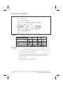
This test prints seven pre-programmed label formats at different speeds.
The printer automatically pauses after each format. The sequence of label formats is as follows:
Quantity
Inches
per second
Left Ribbon Wrinkle Test
20
D*
Right Ribbon Wrinkle Test
20
D*
C39 Wrinkle Test
20
D*
Left Ribbon Wrinkle Test
20
A
Right Ribbon Wrinkle Test
20
A
C39 Wrinkle Test
20
A
Usable Area Test
10
D*
Head Temperature Test
10
D*
Upper Smear Test
10
D*
Lower Smear Test
10
D*
Usable Area Test
10
A
Head Temperature Test
10
A
Upper Smear Test
10
A
Lower Smear Test
10
A
Label Format
* “C” for the 105Se with the 300 dots/inch printhead
Extended Printer Diagnostics
Extended diagnostic tests are available. The maintenance manual,
Vol. 1: General Maintenance (part # 38452L), provides the information
needed to perform these additional tests.
Zebra S-Series User’s Guide
3-13
49
Sample ZPL II Label Formats
ZPL II® is Zebra Technologies Corporation’s Zebra Programming Language II label design language. ZPL II lets you create a wide variety of
labels from the simple to the very complex, including text, bar codes,
and graphics.
This section contains three sample label formats for you to begin experimenting with. It is not intended as an introduction to ZPL II. To
learn about ZPL II, send in the request card at the beginning of this
book for a copy of the ZPL II Programming Guide.
For each format, do the following:
1. Save the file.
2. Copy the file to the printer.
• Set-up the printer and turn the Power ON.
• Use a text editing program (ex: Windows Write or DOS Editor) and
type in the label format exactly as shown in the sample label format
shown below.
• Save the file in a directory for future use. Use the extension “ . zpl”.
• Copy the file to the Zebra S-Series Printer.
Note:
Typically, computers running DOS use the “COPY” command
to send a file to the Zebra printer. For example, if your file
name is “format1.zpl” then type, “COPY FORMAT1.ZPL
COM1”.
3. Compare your results with those shown. If your printout does not look
like the one shown, confirm that the file you created is identical to the
format shown, then repeat the printing procedure. If nothing prints, refer to “Installation” to make sure your system is set up correctly, otherwise refer to “Troubleshooting.”
3-14
Zebra S-Series User’s Guide
50
Format 1: Simple Text and a Barcode
Line
Type this label format:
Youll get this printout:
#
1
2
3
4
5
^XA
^LH30,30
^FO20,10^AD^FDZEBRA^FS
^FO20,60^B3N,Y,20,N^FDAAA001^FS
^XZ
Line #1: Indicates start of label format.
Line #2: Sets label home position (in dots) from the upper left-hand corner of the label.
Line #3: Sets field origin, selects font “D”, defines field data as “ZEBRA”.
Line #4: Sets field origin, selects bar code Code 39, sets barcode height at 20 dot rows,
defines field data for bar code as “AAA001".
Line #5: End of label format.
Format 2: Saving a Label Format As a Graphic Image
Line
Type this label format:
Youll get this printout:
#
1
2
3
4
5
6
^XA
^LH30,30
^FO20,10^AD^FDZEBRA^FS
^FO20,60^B3N,Y,20,N^FDAAA001^FS
^ISFORMAT2,N
^XZ
7
8
9
^XA
^ILFORMAT2
^XZ
(Same as Format 1, but this format was also
saved in the printers memory as a graphic image named FORMAT2".)
Line #1-4: These commands were described in Format 1.
Line #5: Saves the format in the printer’s memory as a graphic image named
“FORMAT2", the ”N" indicates “do not print after saving”.
Line #6-7: (See Format 1)
Line #8: Load and print the graphic image saved as “FORMAT2".
Line #9: (See Format 1)
Zebra S-Series User’s Guide
3-15
51
Format 3: Using a Serialized Data Field
Line
Type this label format:
Youll get this printout:
#
1
2
3
4
5
6
7
^XA
^LH30,30
^FO20,10^AD^FDZEBRA^FS
^FO20,60^B3,,40,,^FDAAA001^FS
^FO20,180^AF^SNSERIAL NUMBER
00000000111,1,Y^FS
^PQ10
^XZ
Ten labels should print. The first and
last are shown here.
Line #1 - 3: These commands were described in Format 1.
Line #4: Defines field data for bar code as “AAA001".
Line #5: Defines serialized field, starting value of 111, increment by 1, insert leading zeros.
Line #6: Sets print quantity to 10
Line #7: (See Format 1)
3-16
Zebra S-Series User’s Guide
52
Configuration and Calibration
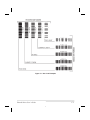
Option Switches
These switches are located at the
rear of the printer above the Signal
Interface Cable Connection. See
Figure 4.2.
In the tables on the following page,
an “R” means the switch is OFF (positioned to the right), while an “L”
means the switch is ON (positioned
to the left). All switches are in the
OFF position when the printer is
shipped from the factory.
Figure 4.1 Option Switches
Figure 4.2 Location of Option Switches
Zebra S-Series User’s Guide
4-1
53
Bank 1 (For Serial Interface Printers Only)
The S-Series Printer, with the
RS-232 Serial Interface, uses
eight miniature switches located
on the rear of the printer, above
the Signal Interface Cable Connector. The ON/OFF positions
of these switches establish some
of the Printer Configuration Parameters. Bank 1 switches must
be properly positioned to establish serial data communications
with the host computer. Thereafter, the position of these
switches should not be changed.
Note:
Parallel-interface
printers do not require
these configuration
parameters, therefore
they have no Bank 1
switches.
If these switches are in the
proper position to match the
communication configuration of
the host computer, and the
printer is not receiving data, refer to “Interconnections” and
make sure the correct interface
cable is being used.
Note:
The printer is fixed at 1
stop bit, so make sure
that your host device is
also set at 1 stop bit.
4-2
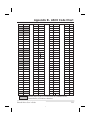
Bank 1 (Serial Interface Printers Only)
Switch
Baud Rate
3 2 1
R R R
9600 baud
R R L
19200 baud
R L R
110 baud
R L L
300 baud
L R R
600 baud
L R L
1200 baud
L L R
2400 baud
L L L
4800 baud
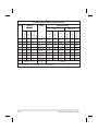
Switch
(Must be set to 8 Data Bits to use Code
4
Data Bits
Page 850.)
R
7 Data bits
L
8 Data bits
Switch
6 5
Parity
(If you choose 7 data bits, you must
choose either even or odd parity.)
R R
Even parity
R L
Parity disabled
L R
Odd parity
L L
Parity disabled
Switch
Communication
7
Handshake Control
R
XON/XOFF control
L
DTR/DSR control
Switch
8
Error Detection Protocol
R
No error detection
L
Error detection active
Table 4.1
Zebra S-Series User’s Guide
54
Bank 2
These switches can manually override any ZPL II commands that affect
print mode, media mode, and media type. They can also override settings established during the calibration procedure. Reasons why you
might want to use these override switches:
Bank 2
Switch
Print Mode
321
• Lets you use a single ZPL II label format for
many different printers—without worrying if
the format contains a mode command that is
inappropriate for your printer configuration.
RRL
Cutter
RLL
Tear-Off
LRL
Peel-Off
LLL
Rewind
- - R
Override is disabled
Switch
654
RRL
Media Mode
Black-mark sensing mode
Transmissive sensing mode with
RLL
non-continuous media (detects a
web/notch)
LLL
- - R
Switch
87
• Troubleshooting. By using these switches,
you know beyond a doubt what operating
mode your printer is in.
Transmissive sensing mode with
continuous media
Override is disabled
Media Type
RL
Thermal transfer
LL
Direct thermal
- R
Override is disabled
Table 4.2
• Some third-party label design software packages work better if these switches control the
mode.
If you do not want to override ZPL II or the
calibration settings, disable one or more of the
override options by setting switches 1, 4, and/or
7 to the R (OFF) position and turning the power
ON. With these disabled, the printer will require ZPL II commands and/or re-calibration to
set print mode, media mode, and/or media type.
To override, set the switches to one of the
modes shown in the table. If you are in the process of printing, this change takes effect on the
next label printed. If you change the switches
from active to disabled after printer power-up,
the printer remains in the current mode until a
ZPL II command or re-calibration changes the
mode.
105Se Note: Switch 5 must not be positioned to the right unless the
printer is equipped with the optional black mark sensor.
Zebra S-Series User’s Guide
4-3
55
Configuration Mode
The Configuration Mode allows you to fine-tune the internal printer
configuration settings for your application. In this mode, you can
change the following parameters:
• Printing darkness
• Rest position of the media with respect to the “web” or “interlabel
gap”
• Position of printing relative to the top of the label
• Media and Ribbon Sensor values
• Label length
• Printing method
• Media type (continuous or non-continuous)
You can get a printout of the printer configuration (the values for each
of these parameters) at any time by performing the CANCEL Key Self
Test (see “Operation”).
If it is ever necessary to reset the printer configuration to the factory defaults, refer to the “FEED Key and PAUSE Key” Self Test description in
“Operation.”
The ZPL II Programming Guide contains information on instructions
that may be sent to the printer to disable the MODE key and set specific
label format values for each of these parameters. If you are not using
ZPL II, refer to the instructions provided with your software package to
determine if you also have this capability.
Calibration
IMPORTANT: Perform the Calibration Procedure when media and
ribbon are first installed and each time a different type of media or ribbon is installed.
4-4
Zebra S-Series User’s Guide
56
During this procedure, the printer automatically determines the media
type, label length, media and ribbon sensor settings, and printing
method. Media type is determined by sensing either continuous or
non-continuous media as blank labels move through the printer. If
non-continuous media is sensed, Label Length is also calibrated. If ribbon is sensed, the Thermal Transfer Print Method is configured. If no
ribbon is present, the Direct Thermal Print Method is configured.
The results of this calibration are stored in the printer’s memory. These
parameters will remain in effect until the next calibration is performed.
The Printer Configuration Printout, which prints when the CANCEL
Key Self Test is performed, lists these results as well as other printer
parameters.
Note:
If the printer is in the Peel-Off Mode, the operator must
“catch” the labels as they are peeled away from the backing
during this procedure.
1. Load media and ribbon (if used). Make sure the Media Sensor is properly positioned (see “Adjustments”).
IMPORTANT: To use the Black-Mark Sensing Mode, make sure you
set the Bank 2 DIP switches appropriately (see page 4-3).
2. Turn the power switch ON. When the Power ON Self Test is complete,
the POWER, PAUSE, and PAPER/RIBBON lights will be ON.
3. Press the MODE key three times briefly. PAUSE and CALIBRATE
lights turn ON.
4. Press UP (FEED Key) to calibrate. The printer feeds some media. The
MODE lights will flash ON and OFF to indicate that the settings have
been saved in memory.
5. Press PAUSE to exit PAUSE mode. PAUSE light turns OFF.
Zebra S-Series User’s Guide
4-5
57
Adjusting the Print Darkness
This procedure sets the darkness of the printing on the label. Use the
lowest setting which provides the necessary print quality.
1. Press the MODE key. PAUSE and DARKEN lights turn ON.
2. Press UP or DOWN to adjust the current setting.
3. Press the MODE key three times. The MODE lights will flash ON and
OFF to indicate that the settings have been saved in memory.
4. Press PAUSE to exit PAUSE mode. PAUSE light turns OFF.
Adjusting the Media Rest Position
This procedure sets the end-of-label position relative to the Tear-Off
Bar or Cutter.
1. Press the MODE key twice briefly. PAUSE and POSITION lights turn
ON.
2. Press UP or DOWN to adjust the current setting.
3. Press the MODE key twice briefly. The MODE lights will flash ON
and OFF to indicate that the settings have been saved in memory.
4. Press PAUSE to exit PAUSE mode. PAUSE light turns OFF.
Adjusting the Position of the Top of the Label
This procedure positions the printing on the label relative to the top
edge of the label.
1. Press the MODE twice briefly then press and hold for about five seconds until the lights change. PAUSE and DARKEN and CALIBRATE
lights turn ON.
2. Press UP or DOWN to adjust the current setting.
3. Press the MODE key twice briefly. The MODE lights will flash ON
and OFF to indicate that the settings have been saved in memory.
4. Press PAUSE to exit PAUSE mode. PAUSE light turns OFF.
4-6
Zebra S-Series User’s Guide
58
Interconnections
System Components
Figure 5.1 System Components
System Considerations
Communications Code
The Zebra S-Series Printer sends and receives American Standard Code
for Information Interchange (ASCII). This code consists of 128 characters (256 for Code Page 850) including upper and lower case letters,
punctuation marks, and various control codes.
Interfaces
The method of interfacing the Zebra S-Series Printer to a data source
depends on the communication options installed in the printer. Depending on how the printer was ordered, the interface is either an RS-232 serial data port or a parallel port.
Zebra S-Series User’s Guide
5-1
59
Data Specifications
When communicating via the serial data port (RS-232), the baud rate,
number of data bits, and the parity are user-selectable (see “Configuration and Calibration” for acceptable setting combinations). Parity only
applies to data transmitted by the printer, since it ignores the parity of received data. The S-Series Printer is fixed at 1 stop bit, so make sure that your
host is also set at 1 stop bit.
When communicating via the parallel port, the previously mentioned
parameters are not considered.
RS-232 Serial Data Port
The connections for the standard interface are made through the DB25S
connector on the rear panel. For all RS-232 input and output signals, the
S-Series Printer follows both the Electronics Industries Association’s (EIA)
RS-232 and the Consultative Committee for International Telegraph and Telephone (CCITT) V.24 standard signal level specifications.
Pin No.
1
Description
Frame Ground for Cable Shield
2
TXD (Transmit Data) output from the printer
3
RXD (Receive Data) input to the printer
4
RTS (Request To Send) output from the printer
6
DSR (Data Set Ready) input to the printer
7
Signal Ground
20
DTR (Data Terminal Ready) output from the printer
Note:
Pins 5, 8, 10-19, and 21-25 are not used and are unterminated.
Table 5.1 RS-232 Pinouts
5-2
Zebra S-Series User’s Guide
60
Hardware Control Signal Descriptions
Request To Send (RTS) is a Control Signal from the S-Series Printer to
the host computer. RTS is always in the ACTIVE condition (positive
voltage) whenever the printer is powered ON.
Data Set Ready (DSR) is a control signal from the host computer to the
printer. When DSR is in the ACTIVE condition (positive voltage), the
printer can transmit status to the host. When CTS is in the INACTIVE
condition (negative voltage), the printer will not transmit any data.
When DTR/DSR handshaking is selected, via DIP Switch #7 at the rear
of the printer, the Data Terminal Ready (DTR) Control Signal output
from the printer controls when the host computer may send data. DTR
ACTIVE (Positive voltage), permits the host to send data. When the
printer places DTR in the INACTIVE (negative voltage) state, the host
must not send data.
Note:
When XON/XOFF handshaking is selected, data flow is
controlled by the ASCII Control Codes DC1 (XON) and DC3
(XOFF). The DTR Control lead will have no effect.
RS-232 Cabling Requirements
The required cable must have a 25-pin “D” Type (DB25P) male connector on one end, which is plugged into the mating (DB25S) female
connector located at the upper rear of the printer. Tighten the locking
screws.
The other end of the Signal Interface Cable connects to an appropriate
point at the host computer. This cable will be one of two types depending on the specific interface requirements. Refer to the following pages
for information on the standard and null modem cables.
Data cables must be fully shielded and fitted with metal or metallized
connector shells. Shielded cables and connectors are required to prevent radiation and reception of electrical noise.
Zebra S-Series User’s Guide
5-3
61
To minimize electrical noise pickup in the cable:
• Keep data cables as short as possible.
• Do not bundle the data cables tightly with power cords.
• Do not tie data cables to power wire conduits.
Interconnect to DTE Devices
The printer is configured as Data
Terminal Equipment (DTE). To
connect the printer to other DTE devices (such as the serial port of a
PC), use an RS-232 Null Modem
(crossover) cable. Figure 5.2 illustrates the connections required for
this cable.
Figure 5.2 DTE to DTE Connections
Interconnect to DCE Devices
When the printer is connected via its
RS-232 interface to Data Communication Equipment (DCE) such as a
modem, use a standard RS-232
(straight-through) interface cable.
Figure 5.3 illustrates the connections
required for this cable.
Figure 5.3 DCE to DTE Connections
5-4
Zebra S-Series User’s Guide
62
Parallel Cabling Requirements
The required cable must have a standard 36-pin parallel connector on
one end, which is plugged into the mating connector located at the upper rear of the printer. The parallel interface cable is connected using
bail clips, instead of screws, in a similar position to that of the serial
data cable.
The other end of the parallel interface cable connects to an appropriate
point at the host computer.
Data cables must be fully shielded and fitted with metal or metallized
connector shells. Shielded cables and connectors are required to prevent radiation and reception of electrical noise.
To minimize electrical noise pickup in the cable:
• Keep data cables as short as possible (maximum length: 10 ft.).
• Do not bundle the data cables tightly with power cords.
• Do not tie data cables to power wire conduits.
Parallel Interface
The Parallel Interface provides a means of communication that is typically faster than the previously mentioned Serial Interface method. In
this method, the bits of data which make up a character are sent all at one
time over several wires in the cable, one bit per wire.
Data signals are defined as either HIGH or LOW, while Control Signals are either Active or Inactive. Some Control Signals are active
HIGH while others are active LOW. The voltage levels which represent these conditions are:
Data Signal
HIGH
LOW
Voltage Level
+5 VDC
0 VDC
Zebra S-Series User’s Guide
5-5
63
Signal Descriptions
The following chart provides a description of each of the pins in the
parallel connector. A standard parallel data cable will provide the required interconnection between the computer and the printer.
Parallel Connector Pin Assignments
Description
Pin No.
1
The nStrobe printer input has internal 3.3 kW pull-up resistors to 5 V (IOL= 1.5 mA) and is
designed to receive a signal driven open collector V OL <= 0.8 V. This pin is a signal from
the host computer. The nStrobe input is debounced on a LOW going edge to require an active width greater than 0.5
2-9
µs before data is latched.
Data inputs have TTL input characteristics with internal 3.3 kW pullups and represent 1 TTL
unit load or less. The Data inputs are positive logic with a HIGH voltage level corresponding
to a logic 1. Pin 2 through Pin 9 = D0 through D7 respectively.
10
The nAck output is an active LOW pulse used to indicate termination. nAck is a driven open
collector with a 3.3 kW internal pull-up. The output sinks 7 mA to a V OL <= 0.4 V.
11
The Busy output is active HIGH whenever the printer
cannot accept data due to any normal
or abnormal condition, including buffer overflow, head open, over temperature, and media error conditions. Busy is a driven open collector with a 3.3 kW internal pull-up. The output
sinks 7 mA to a VOL <= 0.4 V.
12
The PError signal is active HIGH whenever the printer is out of media or ribbon.
13
The Select signal function is determined by an additional configuration option which becomes active when the port is present. In the default condition, Select is active HIGH whenever the parallel port is powered up and the parallel port is enabled. In the non-default
condition, Select will go active LOW whenever the printer is printing.
14
nAutoFd (not connected)
15
Not defined
16
Logic Gnd
17
FRAME GROUND is at the same potential as Logic Gnd (pin 16).
18
FUSED 5 V - 1 A maximum.
19 - 30
SIGNAL GROUNDS are the Logic Grounds and Returns for all input and output signals.
31 - 35
NOT USED - These leads should be left unconnected.
36
NSelectIn (not connected)
5-6
Zebra S-Series User’s Guide
64
Preventive Maintenance
Overview
This section contains preventive maintenance information for the Zebra
S-Series Printer. These procedures may be performed by the operator.
Cleaning
Exterior Surfaces
The exterior surfaces of the printer may be cleaned as required by using
a lint free cloth. Do not use harsh or abrasive cleaning agents or solvents. If necessary, a mild detergent solution or desktop cleaner may be
used sparingly.
Interior
Remove any accumulated dirt/lint from the interior of the printer using
a soft bristle brush and/or vacuum cleaner. This area should be inspected after every four rolls of media.
AREA
METHOD
Printhead
Isopropyl alcohol
Platen Roller
Isopropyl alcohol
Upper and Lower
Air blow
INTERVAL
After every roll of media (or 500
ft. of fanfold media) when printing direct thermal or after every
roll of ribbon when printing in
Media Sensors
thermal transfer mode.
Media Path
Isopropyl alcohol
Ribbon Sensor
Air blow
Peel/Tear Bar
Isopropyl alcohol
As needed.
Label Available Sensor
Air blow
Monthly.
Cutter Module
Isopropyl alcohol and/or air blow
As needed.
Table 6.1 Cleaning Schedule
Zebra S-Series User’s Guide
6-1
65
Printhead and Platen Roller
Inconsistent print quality, such as voids in the bar code or graphics, may
indicate a dirty printhead. For optimum performance, Zebra recommends performing the cleaning procedure on page 6-3 after every roll
of ribbon (after every roll of media, for direct thermal printing).
Note:
Label Available Sensors are shown for location purposes only.
They are not standard on all printers.
Figure 6.1 Printhead Cleaning (105Se shown)
6-2
Zebra S-Series User’s Guide
66
It is not necessary to turn printer power OFF prior to cleaning. If power is
turned OFF, all label formats, images, and parameter settings stored in the
printer’s formatting RAM will be lost. Permanent parameter settings stored
in EEPROM will be retained. When power is turned back ON, it may be
necessary to reload some items.
To clean the printhead and platen roller, open the media compartment door,
refer to Figure 6.1, and perform the following steps:
1. Open the printhead by moving the printhead handle to the OPEN position.
2. Remove the media and ribbon (if present).
3. Moisten an applicator tip with Zebra Technologies Corporationrecommended solvent and wipe the print elements from end to end.
(The print elements form the gray/black strip just behind the chrome
strip. See Figure 6.1.) Allow a few seconds for the solvent to evaporate.
4. Rotate the platen roller and clean thoroughly with the solvent.
5. Brush/vacuum any accumulated paper lint and dust away from the rollers and the media and ribbon sensors.
6. Reload ribbon and/or media, close and latch the printhead, restore
power (if necessary) and continue printing after the self test.
Media, Ribbon, and Label Available Sensors
These sensors should be cleaned on a regular basis to ensure proper operation of the printer. To locate the position of these sensors, refer to
Figures 6-1, 7-2, and 7-3.
Cutter Module
Periodically, the Cutter Module should be cleaned to remove paper dust
and label residue. Cleaning the Cutter Module ensures that labels will
be cut properly and not jam in the cutter mechanism. Refer to
Figure 6.2.
Zebra S-Series User’s Guide
6-3
67
Clean the stationary cutter blade with a cotton swab moistened with isopropyl alcohol when it becomes gummed up with label adhesive or paper debris. If the cutter performs unsatisfactorily after it has been
cleaned, refer to Volume 1 of the Maintenance Manual.
Figure 6.2 Cleaning the Cutter Blade
Lubrication
CAUTION: Some commercially available lubricants will damage the
printer if used.
Lubrication of the Zebra S-Series Printer should be performed by a
qualified service technician according to the directions provided in the
Volume 1 of the Maintenance Manual (part # 38452L).
6-4
Zebra S-Series User’s Guide
68
Adjustments
Toggle Positioning
Note: The 105Se has one toggle, the 160S printer has two toggles.
The toggle(s) should be positioned to provide even pressure on the media. Toggles are positioned by sliding them left or right to the
desired location. On the 105Se, the single toggle should normally be
positioned over the center of the media. If your printer has two toggles
and you are using media too narrow to accommodate both toggles, position one toggle over the center of the media and decrease the pressure
on the unused toggle.
Printhead Pressure Adjustment
If printing is too light on one side, or if thick media is used, you may
need to adjust the printhead pressure. Refer to Figure 7.1 and follow
the procedure below.
1. Perform a PAUSE Key Self Test.
2. Lower the Darkness Setting until the printing is gray.
3. Loosen the Toggle Position locking nut(s) located inside the “U”
shaped bracket at the top of the toggle.
4. Slide toggle(s) in the direction of the light printing.
5. Using the knurled Adjusting Nuts on the shaft(s) of the toggle(s), increase or decrease spring pressure until the left and right edges of the
printed area are equally dark.
6. Increase Darkness to optimum level for the media being used.
7. Retighten the Toggle Position locking nut(s).
Note:
Printhead life can be maximized by using the lowest pressure
that produces the desired print quality.
Zebra S-Series User’s Guide
7-1
69
Figure 7.1 Printhead Pressure Adjustment (105Se shown)
Black Mark Media Sensor Position Adjustment
This sensor position requires no adjustment or calibration by the user.
Transmissive Media Sensor Position Adjustment
The transmissive media sensor senses either the “web” between labels or a hole
or notch in the media to determine the length of the label or ticket. The
factory-set position should be sufficient for any width label using media with a
web. However, if position adjustments are needed, follow these procedures beginning with the upper sensor.
7-2
Zebra S-Series User’s Guide
70
Upper Transmissive Media Sensor Position Adjustment
To adjust the upper media sensor, refer to Figure 7.2 and follow these
steps.
1. Remove the ribbon and locate the Upper Media Sensor.
2. Loosen the Phillips head screw.
3. Slide the upper sensor along the slot to the desired position. When using
media that has a web between labels, position the media sensor anywhere
along the web (except if you have labels with rounded corners, do not position the sensor where the rounded corners of the label might be detected).
When using tag stock, position the upper sensor directly over the hole or
notch.
4. Tighten the Phillips head screw.
Note:
To adjust the upper section of the Transmissive Media Sensor
for the outside half of the media width, call a service
technician.
Figure 7.2 Upper Media Sensor (105Se shown)
Zebra S-Series User’s Guide
7-3
71
Lower Transmissive Media Sensor Position Adjustment
To adjust the lower media sensor, follow these steps.
1. Locate the lower media sensor assembly (a spring clip holding a small
printed circuit board) under the rear idler roller.
2. Position the sensor so that the two brass-colored infrared emitters are
under the upper sensor by sliding it in its slot.
3. Gently pull wires out of the printer frame as required. (Wires should
have a little slack.)
Note:
If the sensor is being moved inward and a large loop of wire
develops, remove the cover from the electronics side of the
printer and gently pull the wires through. It is important that
the wires be properly clamped so that they are not rubbed by
any belts.
Figure 7.3 Lower Transmissive Media Sensor Locations
7-4
Zebra S-Series User’s Guide
72
Media and Ribbon Sensor Sensitivity Adjustment
Note:
This adjustment is initially set by Zebra Technologies
Corporation during final printer calibration. Under normal
circumstances, further adjustments should not be necessary.
The exception to this might be the use of media with
exceptionally thick or thin backing, which could require
re-adjustment of the Sensor Sensitivity.
This adjustment may need to be performed if the Paper/Ribbon light
comes ON with (1) the media and ribbon properly installed for thermal
transfer mode or (2) media only properly installed for the direct thermal
mode.
The following procedure is used to perform the Media and Ribbon Sensor and Sensitivity Range Adjustment.
1. Turn the printer OFF.
2. Open the printhead.
3. Remove as many labels as needed to create at least 12 inches of blank
backing material. Load the blank backing material under the printhead.
Note:
Be sure that blank backing material is positioned between the
upper and lower Media Sensors.
4. Remove the ribbon. (Sliding it as far from the printer wall as possible
will have the same effect as removing it.)
5. Close the printhead.
6. Hold the PAUSE, FEED, and CANCEL keys depressed while turning
the printer ON. Once the printer is ON, release the keys.
7. The following two sets of lights will begin flickering, signifying that the
adjustment has been made.
• The PRINTHEAD and PAPER/RIBBON lights
• The DARKEN and POSITION lights
Zebra S-Series User’s Guide
7-5
73
Note:
If only one pair of lights is flickering, it indicates that the
adjustment was not successful. Go back to step 1 and start
over.
8. Open the printhead.
9. Pull the media out of the printer until a label is positioned under the
printhead. Move the ribbon back to its normal position.
Note:
Be sure that label is positioned between the upper and lower
Media Sensors.
10. Close the printhead.
11. Press the MODE key to print a Media and Sensor Profile and save the
new values (see Figure 7.4.).
12. Perform the Media Calibration procedure in “Configuration and Calibration.”
Figure 7.4 Media Sensor Profile Sample Printout
7-6
Zebra S-Series User’s Guide
74
Troubleshooting
This section contains troubleshooting charts used to localize and repair
the printer when faults occur. The procedures called out in the
ACTION column may be performed by the operator or by a service
technician when indicated.
SYMPTOM
All indicator lights never light.
DIAGNOSIS
ACTION
No AC Power applied to the
Ensure that the AC power cable is con-
printer.
nected to a working voltage source.
Faulty AC power fuse.
Refer to Installation for fuse replacement procedures.
No voltage available from the
Call a service technician.
internal power supply.
Printer locks up when running
An improper configuration was Reload factory defaults. Then, set cor-
Power-On Self Test.
set.
rect parameters. See Operation.
POWER light ON, other lights
ROM CRC test has failed.
Call a service technician.
Dynamic RAM failed.
Call a service technician.
FONT ROM error.
Call a service technician.
PRINTHEAD light is ON,
Printhead under-temperature
Wait until printhead warms up. If con-
printing continues.
condition.
dition persists and print quality is af-
all OFF or all ON and the
printer locks up.
CALIBRATE light is OFF but
all other lights are ON.
CALIBRATE light and
POSITION light OFF but all
other lights ON.
fected, move printer to a warmer
environment. If print quality is acceptable, no action is required.
Printer stops. PAUSE light and
Media incorrectly loaded or not Load media correctly. See Media Load-
PAPER/RIBBON light both
loaded.
ing in Installation.
Misadjusted Media Sensor.
Check position and sensitivity of Media
ON.
Sensor and/or calibrate media. See
Media not calibrated.
Adjustments and Configuration and
Calibration.
Zebra S-Series User’s Guide
8-1
75
SYMPTOM
DIAGNOSIS
ACTION
Printer stops. PAUSE light ON
Ribbon incorrectly loaded or
Load ribbon correctly. See Ribbon
and PAPER/ RIBBON light
not loaded.
Loading in Installation.
Malfunctioning Ribbon Sensor.
Call a service technician.
Printhead is not fully closed.
Close printhead completely.
Printhead Open Sensor not de-
Call a service technician.
FLASHING.
Printer stops. PAUSE light
ON and PRINTHEAD light
FLASHING.
tecting its position flag.
Printer stops. PAUSE light
Printhead element is over-
Printer resumes printing when the print-
and PRINTHEAD light
heated (105Se or 160S).
head element cools. If condition persists, move printer to a cooler
both ON.
environment.
Power supply is overheated
Printer resumes printing when the
(105Se or 160S).
power supply cools. If condition persists, move printer to a cooler environment.
Dots missing in printed area of
Printhead element going bad.
Call a service technician.
Loss of printing registration on
Possible media sensor or cali-
Adjust media sensor position or cali-
labels.
bration problem.
brate media. Call a service technician
label.
if necessary.
Printer set for non-continuous
Set printer for correct media. See In-
media, but continuous media
stallation.
loaded.
For Peel-Off Mode.
Improperly adjusted Media
Refer to Installation.
Edge Guides.
Excessive vertical drift in top-
Incorrect media loading.
See Media Loading in Installation.
Dirty head or ribbon rollers.
See Printhead Cleaning in Preventive
of-form registration.
Light vertical lines running
through all labels.
Light printing or no printing on
Maintenance.
Defective printhead elements.
Call a service technician.
Printhead needs balancing.
Adjust toggle pressure and/or position.
Too much printhead pressure.
Adjust toggle pressure and/or position.
Wrinkled ribbon.
See Wrinkled Ribbon in this table.
the left or right side of the label.
Short printed lines at 45° to label edge on left or right side of
label.
Fine gray lines on blank labels
at angles.
8-2
Zebra S-Series User’s Guide
76
SYMPTOM
DIAGNOSIS
ACTION
Truncated print, no print, or
Media or ribbon improperly
See Media Loading and Ribbon Load-
FEED button operates incor-
loaded.
ing instructions in Installation.
Wrinkled ribbon.
See Wrinkled Ribbon in this table.
Print element damaged.
Call a service technician.
In Peel-Off Mode, skewed or
Glue material from back of la-
Refer to Preventive Maintenance and
stuck labels.
bels causing media movement
perform maintenance and cleaning of
problems.
the printer.
Media and backing not prop-
Refer to Installation.
rectly while using noncontinuous media.
Long tracks of missing print on
several labels.
erly aligned in printer.
Wrinkled ribbon.
Ribbon fed through machine
See Ribbon Loading in Installation.
incorrectly.
Incorrect Darkness setting.
Set to the lowest value needed for good
print quality.
Incorrect printhead
Adjust toggle pressure and/or position.
position or pressure.
Media not feeding properly; it
Make sure the media is snug by adjust-
is walking from side to side.
ing the media guides.
Continuing symptoms.
Call a service technician.
Continued wrinkled ribbon.
Strip plate needs adjusting.
Call a service technician.
Misregistration and misprint of
Media was pulled when motor
Enter Calibrate Mode and recalibrate.
1 to 3 labels.
was not moving.
Incorrect Media Sensor posi-
See the media sensor position adjust-
tion.
ments in Adjustments.
Media or ribbon improperly
See Media and Ribbon Loading in In-
loaded.
stallation.
Incorrect Media Sensor
See Configuration and Calibration.
position or sensitivity.
Changes in parameter settings
Parameters are set or saved in-
Reload the factory defaults. Refer to
did not take effect.
correctly.
Operation and calibrate the printer.
Then, cycle the power ON/OFF Switch.
If problem continues, there
Call a service technician.
may be a problem on the main
logic board.
Zebra S-Series User’s Guide
8-3
77
SYMPTOM
DIAGNOSIS
ACTION
ZPL II was sent to printer, but
Communications parameters or See Operation and perform MODE
not recognized. The DATA
DIP switches are set incor-
Key Self Test. Check for format or
light remains OFF.
rectly.
overrun errors. Reset Communication
parameters if needed.
Prefix and delimiter characters
Set the characters in the printer to
set in printer configuration do
match ZPL II format. Check Configu-
not match the ones sent in the
ration Label for correct characters. If
ZPL II label formats.
problem continues, check the ZPL II
format for changed ^CC, ^CT, and
^CD instructions.
Printer does not operate in the
Bank 2 DIP switches set to
mode specified in ZPL II or by
override ZPL II and calibra-
calibration
tion.
Printer does not feed media
Printer not set up correctly.
with black marks correctly.
Check Bank 2 DIP switch settings.
See Configuration and Calibration
recalibrate printer.
See Configuration and Calibration to
check Bank 2 DIP switch settings.
Sensor is broken. (No red light Call a service technician.
is visible when looking through
the front of the printer with the
printhead open.)
In Cutter Mode, skewed or
Cutter is dirty.
Follow cutter module cleaning proce-
stuck labels.
The cutter is not cutting labels
dure in Preventive Maintenance.
Cutter is dirty.
Follow cutter module cleaning proce-
cleanly.
Labels jamming in cutter, or la-
dure in Preventive Maintenance.
Cutter blades are dull.
Replace the Cutter Module.
Cutter is dirty.
Follow cutter module cleaning procedure in Preventive Maintenance.
bels are being cut more than
once.
Label length is too short.
8-4
Increase label length.
Zebra S-Series User’s Guide
78
SYMPTOM
For printers with the Cutter
Option installed: Printing
stops. PAPER/RIBBON,
PAUSE, and CANCEL LEDs
on.
DIAGNOSIS
ACTION
Media jammed in Cutter.
Remove media, clean Cutter Module.
Connecting cable not con-
Plug cable into Cutter Module.
nected to Cutter Module.
Cutter Module is dirty.
Clean Cutter Module.
End of the media is not posi-
Re-position media so that the end is on
tioned correctly on top of the
top of the platen.
platen.
Zebra S-Series User’s Guide
8-5
79
80
Options
Peel-Off
Your printer may be equipped with the Peel-Off option. In the Peel-Off
Mode, only the label backing rewinds onto the Rewind Spindle. The
Peel/Tear Bar separates the label from the backing and the Label Available Sensor activates the PAUSE mode to allow the operator to remove
a printed label before subsequent labels print.
This option cannot be added to a printer equipped with the optional Cutter.
Cutter Module
Your printer may be factory equipped with a Cutter Module that cuts labels after they have been printed. In addition, an optional Cutter Catch
Tray can be added to gather the labels once they have been cut.
Media Rewind
Your printer may be equipped with a Media Rewind Option. This option
supports both the Rewind and Peel-Off modes of operation.
In Rewind mode, both labels and backing material rewind internally
onto a user-supplied three-inch core. A Rewind Bracket guides the media
back to the Rewind Spindle after printing.
This option cannot be added to a printer equipped with the optional
Cutter.
(See Peel-Off Option for Peel-Off mode of operation.)
Zebra S-Series User’s Guide
9-1
81
Fanfold Supply Bin
Your printer may be equipped with an optional internal Fanfold Supply
Bin. It is used to load fanfold media within the media compartment,
and it protects the media from environmental contaminants such as dust
and dirt.
The Fanfold Media Supply Bin is fully adjustable. It accommodates
media from 1.57" (40 mm) to 3.54" (90 mm) wide (7.17" [183 mm]
wide for the 160S) and 3.5" (89 mm) to 8" (203mm) long. The maximum stack height for 8" long media is 4.5". Stack heights of 6.5" may
be achieved with media less than 3.5" long.
The Fanfold Supply Bin may be installed in the field by the operator.
To install the Fanfold Supply Bin, follow the instructions included
with the option.
Note:
The Fanfold Supply Bin, Peel-Off Option, and Rewind Option
are mutually exclusive. The Fanfold Supply Bin may not be
installed in S-Series Printers with the Peel-Off Option or the
Rewind Option. Fanfold media may be used with the Rewind
Spindle installed by using one of the external Fanfold supply
access slots (at the bottom and rear of the printer).
External ZebraNet™ (Ethernet) Interface
Allows you to connect your printer to your ethernet network. Available
for both 10Base-2 and 10Base-T networks.
Black Mark (Reflective) Sensor (105Se Only)
Utilizes continuous media with black marks printed on the back of the
label liner. The Black Mark Sensor determines the label length and the
top of the label by detecting the black mark (similar to the way a Transmissive Sensor detects the gap or notch).
This option is in addition to the standard transmissive sensor and is software- or switch-selectable.
9-2
Zebra S-Series User’s Guide
82
Optional Printer Fonts
The S-Series Printer can be optioned with character fonts in addition to
those which are standard in the unit.
Only one additional font can be installed in the printer at a time. This
installation should be performed by a service technician. Once installed, this font can be used in addition to the standard fonts available
in the printer. Refer to the ZPL II Programming Guide for further application information.
Once an optional font is installed in the printer, the Configuration printout from the CANCEL Key Self Test will indicate the font type.
The following optional scalable smooth fonts are presently available
(each is supplied as a complete set of standard, bold, italic, and bold
italic styles): CG Triumvirate™, CG Times™, CG Palacio™, Futura™,
Univers®.
The following Bitmap Smooth Fonts (supplied in bold style only) are
presently available:
CG Triumvirate™ Bold, CG Triumvirate™ Bold Condensed, Futura™
Bold, Univers® Bold, CG Times™Bold and CG Palacio™ Bold (type
sizes of 6 pt, 8 pt, 10 pt, 12 pt, 14 pt, 18 pt, 24 pt, 30 pt, 36 pt are available.)
Examples of these optional fonts can be found in “Appendix D.”
230 VAC Factory Setup
Your Zebra S-Series Printer will be factory set for 230 VAC operation
if requested when the order is placed. If it is necessary to reconfigure
your printer for operation at 115 VAC, see “Installation.”
Zebra S-Series User’s Guide
9-3
83
512 KB DRAM Memory Expansion (Not available for 105Se
300 dots/inch)
This option increases the printer’s dynamic memory capacity from 0.5
MB to 1 MB. This supports longer label lengths and provides more capacity for downloadable fonts and large graphic image files. Extra
memory may be installed at the factory or in the field.
12-Dot/mm and 6-Dot/mm Printhead (105Se Only)
Optional 300 dot-per-inch and 152 dot-per-inch printhead densities satisfy specified requirements for printing UPC/EAN symbologies or
high-density graphics and small, crisp text.
9-4
Zebra S-Series User’s Guide
84
Appendix A - 230 VAC Power Cord
230 VAC Power Cord
Depending on how the Zebra printer was ordered, a power cord may or
may not be included when the printer is optioned for 230 VAC,
50/60 Hz operation.
If a power cord is not supplied, you will need to obtain one with the following specifications:
• The overall length must be less than 3.8 meters.
• It must be rated for at least 5 amps, 250 V.
• The CHASSIS GROUND (EARTH) MUST BE CONNECTED to
assure safety and reduce electromagnetic interference. This is done
by the third wire in the power cord.
• The plug cap should bear the certification mark of a known international safety organization (see Figure A.2).
Figure A.1 AC Power Cord
Figure A.2 International Safety Organizations
Zebra S-Series User’s Guide
A-1
85
86
Appendix B - ASCII Code Chart
HEX
CHAR
HEX
CHAR
HEX
CHAR
HEX
00
01
CHAR
NUL
20
space
40
@
60
SOH
21
!
41
A
61
a
02
STX
22
42
B
62
b
03
ETX
23
#
43
C
63
c
04
EOT
24
$
44
D
64
d
05
ENQ
25
%
45
E
65
e
06
ACK
26
&
46
F
66
f
07
BEL
27
47
G
67
g
08
BS
28
(
48
H
68
h
09
HT
29
)
49
I
69
i
0A
LF
2A
*
4A
J
6A
j
0B
VT
2B
+
4B
K
6B
k
0C
FF
2C
,
4C
L
6C
l
0D
CR
2D
-
4D
M
6D
m
0E
SO
2E
.
4E
N
6E
n
0F
SI
2F
/
4F
O
6F
o
10
DLE
30
0
50
P
70
p
11
DC1
31
1
51
Q
71
q
12
DC2
32
2
52
R
72
r
13
DC3
33
3
53
S
73
s
14
DC4
34
4
54
T
74
t
15
NAK
35
5
55
U
75
u
16
SYN
36
6
56
V
76
v
17
ETB
37
7
57
W
77
w
18
CAN
38
8
58
X
78
x
19
EM
39
9
59
Y
79
y
1A
SUB
3A
:
5A
Z
7A
z
1B
ESC
3B
;
5B
[
7B
{
1C
FS
3C
<
5C
\
7C
|
1D
GS
3D
=
5D
]
7D
}
1E
RS
3E
>
5E
^
7E
~
1F
US
3F
?
5F
_
7F
DEL
Shaded values are NOT recommended for Command Prefix,
Format Prefix, or Delimiter characters.
Zebra S-Series User’s Guide
B-1
87
88
Appendix C - Adjusting Bar Code Darkness
Adjusting Darkness For “In-Spec” Bar Codes
All direct thermal and thermal transfer materials do not use the same
darkness setting. The best way to check for the proper darkness is to
use a bar code verifier that actually measures bars/spaces and will calculate the Print Contrast Signal (PCS) ratio. Without the assistance of a
verifier, your eyes and/or the scanner to be used in the system may be used
for picking the optimum darkness setting. What follows is a simple yet
effective method for adjusting the darkness to print “in-spec” bar codes.
1. Load media according to the appropriate media loading and ribbon
loading instructions in “Installation.” Ensure that the proper print
method has been selected.
2. With power off, press and hold the FEED key.
3. Turn the printer power on, then release the FEED key. The printer begins printing test labels.
4. Print a label, then press the PAUSE key. The label will contain several
bar codes as well as other printer information. Normal bar codes are
printed in a horizontal format as they feed out of the printer. Rotated
bar codes are printed in a vertical format.
5. Compare the test label printed to the bar codes in Figure C.1. If the test
label appears too dark or too light, increase or decrease the darkness
setting accordingly.
6. Resume printing by pressing the PAUSE key again. Print a few labels
at the new setting and verify that proper “in-spec” bar codes are being
printed. Repeat steps 4, 5, and 6 until satisfied.
7. To stop printing test labels, press the PAUSE key, then press the CANCEL key.
Zebra S-Series User’s Guide
C-1
89
Too Dark - Dark labels are fairly obvious. The normal bar code bars
increase in size, and the openings in small alphanumeric characters may fill
in with ink. It may be readable but not “in-spec”. Rotated bar code bars
and spaces will run together.
Slightly Dark - Slightly dark labels are not as obvious. The normal bar
code will be “in-spec”. Small character alphanumerics will be bold and
could be slightly filled in. The rotated bar code spaces are small when
compared to the “in-spec” code, possibly making the code unreadable.
Slightly Light - Slightly light labels are, in some cases, preferred to
slightly dark for “in-spec” bar codes. Both normal and rotated bar
codes will be “in-spec”, but small alphanumeric characters may not be
complete.
Too Light - Light labels are obvious. Both normal and rotated bar
codes have incomplete bars and spaces. Small alphanumeric characters
are unreadable.
In-Spec - The “in-spec” bar code can only be confirmed by a verifier,
but it should exhibit some very visible characteristics. The normal bar
code will have complete, even bars and clear, distinct spaces. The rotated
bar code will also have complete bars and clear distinct spaces. Although it
may not look as good as a slightly dark bar code, it will be “in-spec”. In
both normal and rotated styles, small alphanumeric characters will look
complete.
C-2
Zebra S-Series User’s Guide
90
Figure C.1 Bar Code Examples
Zebra S-Series User’s Guide
C-3
91
92
Appendix D - Optional Printer Fonts
Your printer can be optioned with character fonts in addition to those
that are standard in the unit. The following pages illustrate the Optional
Fonts in each of the available styles. From time to time, additions may
be made to the list of available fonts. Contact Zebra Technologies
Corporation or your sales representative for further information.
Only one additional font can be installed in the printer at a time. This
installation should be performed by a service technician. Once installed, this font can be used in addition to the standard fonts available
in the printer. Refer to the ZPL II Programming Guide for further application information.
Once an optional font is installed in the printer, the configuration label
printed during the CANCEL Key Self Test will indicate the font type as
the “Socket 2 ID”.
Optional Printer Fonts Currently Available
Scalable Smooth Fonts (each is supplied as a
Bitmap Smooth Fonts (supplied only in Bold). Type
complete set of Normal, Bold, Italic, and Bold
sizes: 6 pt, 8 pt, 10 pt, 12 pt, 14 pt, 18 pt, 24 pt.
Italic styles)
CG Triumvirate
CG Triumvirate
-
CG Triumvirate Condensed*
CG Times
CG Times
CG Palacio
CG Palacio
Futura
Futura
Univers
®
Univers
®
*When equipped with the Bitmap CG Triumvirate™ Bold Condensed font, the 105Se and
®
160S have the same font styles as the Stripe S-300 printer.
Zebra S-Series User’s Guide
D-1
93
CG Triumvirate™ - Normal 0123456789.,?!AaBbCc
CG Triumvirate™ - Bold 0123456789.,?!AaBbCcDd
CG Triumvirate™ - Italic 0123456789.,?!AaBbCcDdEe
CG Triumvirate™ - Bold Italic 0123456789.,?!AaBb
CG Times™ - Normal 0123456789.,?!AaBbCcDdEeFfGg
CG Times™ - Bold 0123456789.,?!AaBbCcDdEeFfGgHh
CG Times™ - Italic 0123456789.,?!AaBbCcDdEeFfGgHhIi
CG Times™ - Bold Italic 0123456789.,?!AaBbCcDdEeFf
CG Palacio™ - Normal 0123456789.,?!AaBbCcDdEeFf
CG Palacio™ - Bold 0123456789.,?!AaBbCcDdEeFfGg
CG Palacio™ - Italic 0123456789.,?!AaBbCcDdEeFfGg
CG Palacio™ - Bold Italic 0123456789.,?!AaBbCcDdEe
CG Futura - Normal 0123456789.,?!AaBbCcDd
CG Futura - Bold 0123456789.,?!AaBbCcDdEe
CG Futura - Italic 0123456789.,?!AaBbCcDdEeFf
CG Futura - Bold Italic 0123456789.,?!AaBbCc
Univers® - Normal 0123456789.,?!AaBbCcDdEeFf
Univers® - Bold 0123456789.,?!AaBbCcDdEeFfGgHh
Univers® - Italic 0123456789.,?!AaBbCcDdEeFfGgHh
Figure D.1 Scalable Smooth Fonts (Optional)
CG Triumvirate™ - Bold 0123456789.,?!AaBbCcDd
CG Triumvirate™ Condensed - Bold 0123456789.,?!AaBb
CG Futura - Bold 0123456789.,?!AaBbCcDdEe
Univers® - Bold 0123456789.,?!AaBbCcDdEeFfGgHh
CG Times™ - Bold 0123456789.,?!AaBbCcDdEeFfGgHh
CG Palacio™ - Bold 0123456789.,?!AaBbCcDdEeFfGg
Figure D.2 Bitmap Smooth Fonts (Optional)
D-2
Zebra S-Series User’s Guide
94
Figure D.3 Point Size Examples
Zebra S-Series User’s Guide
D-3
95
96
Glossary
alphanumeric Indicating letters, numerals, and characters such as punctuation marks.
backfeed The printer pulls the media and ribbon (if used) backward into the printer so that the
beginning of the label to be printed is properly positioned behind the printhead. Backfeed
occurs when you’re operating the printer in tear-off or peel-off mode.
bar code A code by which alphanumeric characters can be represented by a series of adjacent
stripes of different widths. Many different code schemes exist, such as the universal product code (UPC) or Code 39.
black mark sensing See “reflective media sensor”.
calibration (of a printer) A process in which the printer determines some basic information
needed to print accurately with a particular media/ribbon combination. To do this, the
printer feeds some media and ribbon (if used) through the printer and senses whether to use
the direct thermal or thermal transfer print method, whether continuous or non-continuous
media will be used, and (if non-continuous media) the length of individual labels/tags.
character set The set of all letters, numerals, punctuation marks, and other characters that can
be expressed by a particular barcode.
check digit A character added to a barcode symbol that indicates to the scanner that it has read
the symbol correctly.
continuous media Label or tagstock that has no web (space between labels), notch, or gap to
separate each label/tag, but rather the media is one long piece of material.
core diameter The inside diameter of the cardboard core at the center of a roll of media/ribbon.
diagnostics Information about what printer functions are not working. This information is used
for troubleshooting.
direct thermal printing Printing in which direct thermal media is used. No ribbon is used. Instead, the media is coated with a substance which reacts to heat to produce an image.
fanfold media Media that comes folded in a rectangular stack, rather than on a roll.
font A complete set of alphanumeric characters in one style of type (ex: Times, Helvetica).
ips “inches-per-second” The speed at which the label or tag is printed. Zebra offers printers
that can print from 2 ips to 12 ips.
Zebra S-Series User’s Guide
Glossary - 1
97
label An adhesive-backed piece of paper, plastic, or other material on which information is
printed.
label available sensor For printers equipped with the Peel-Off Option, this sensor detects a
printed label waiting to be taken or “picked” by the operator. While it detects this label, the
printer will not print additional labels. Once the label has been taken, printing resumes.
Also called “take-label sensor”.
label backing (label liner) The material on which labels are affixed during manufacture and
which is discarded or recycled by the end-users. Label backing (or liner) has a non-stick
surface which allows the label to be easily removed by the end-user and placed in the desired location.
mark sensing See “reflective media sensor”.
media Material onto which data is printed by the printer. Types of media include: tagstock,
continuous, fanfold, roll, etc.
media hanger The hanger that supports media rolls and provides consistent media feed to the
printhead.
non-volatile memory Electronic memory that retains data even when power is removed.
print speed The speed at which printing occurs. For thermal transfer printers, this speed is expressed in terms of ips (inches per second). Zebra offers printers that can print from 2 ips
to 12 ips.
printhead wear The degradation of the surface of the printhead and/or the print elements over
time. Heat and abrasion can cause printhead wear. Therefore, to maximize the life of your
printhead use the lowest print darkness setting (sometimes called “burn temperature” or
“head temperature”) and the lowest printhead/toggle pressure necessary. Also, use ribbon
that is as wide or wider than the media, to protect the printhead from the rougher media.
reflective media sensor A sensor that detects a black mark on the back of media by measuring
the reflectivity of the media. This mark helps the printer determine label size and print registration.
registration Alignment of printing with respect to the top of a label/tag.
ribbon A band of inked material that is pressed by the printhead against the media to transfer
an image onto the media, which in turn is pressed against the platen. A ribbon consists of a
base film coated with wax or resin “ink”. Zebra ribbons also have a back coating that protects the printhead from damage. The ribbon transfers ink onto the media when heated by
the printhead.
Glossary - 2
Zebra S-Series User’s Guide
98
ribbon wrinkle A wrinkling of the ribbon caused by improper alignment of the strip plate
and/or printhead pressure. This wrinkle can be seen just above the strip plate. Ribbon
wrinkle can cause voids in the print and/or the spent ribbon to rewind unevenly. This is a
condition that should be corrected by performing adjustment procedures.
roll media Media that comes supplied rolled up on a core (usually cardboard). Contrast this
with fanfold media, which comes folded in a rectangular stack.
supplies Supplies is a general term for ribbon and media.
tag A type of media having no adhesive backing but featuring a hole or notch by which the tag
can be hung on something. Usually tags are made of cardboard or other durable material.
take label sensor See “label available sensor”.
thermal direct printing See “direct thermal printing”.
thermal transfer printing A printing method in which the printhead heats an ink- or resincoated ribbon against the media, causing the ink/resin to transfer onto the media. By selectively heating the ribbon, you can form an image on the media. See also “ribbon”.
transmissive media sensor This sensor is located behind the printhead to detect the presence
of media and, for non-continuous media, the position of the web, hole, or notch that separates each label.
void A space where printing should have occurred but, due to some error condition, it did not
occur. A void can cause a bar code symbol to be read incorrectly or not be read at all.
Zebra S-Series User’s Guide
Glossary - 3
99
100
Index
115 VAC Operation . . . . . . . . . . . . . . . . . . . . . 2-3
Printhead and Platen Roller . . . . . . . . . . . 6-2
12-Dot/mm and 6-Dot/mm Printhead . . . . . . . . 9-4
Schedule . . . . . . . . . . . . . . . . . . . . . . . . . . 6-1
Sensors . . . . . . . . . . . . . . . . . . . . . . . . . . . 6-3
230 VAC Operation . . . . . . . . . . . . . . . . . . . . . 2-3
230 VAC Power Cord . . . . . . . . . . . . . . . . . . . A-1
Communications
A
Communications Capabilities
Diagnostic Test . . . . . . . . . . . . . . . . . . . . 3-12
Asynchronous Modems . . . . . . . . . . . . . . 1-1
Additional System Requirements . . . . . . . . . . . 1-3
Host Systems. . . . . . . . . . . . . . . . . . . . . . . 1-1
Adjustments
Configuration Mode . . . . . . . . . . . . . . . . . . . . . 4-4
Bar Code Darkness. . . . . . . . . . . . . . . . . . C-1
Connection Recommendations
Black Mark Media Sensor . . . . . . . . . . . . 7-2
and Cautions . . . . . . . . . . . . . . . . . . . . . . . . 1-4
Lower Transmissive Media Sensor. . . . . . 7-4
Cutter Mode Media Loading. . . . . . . . . . . . . . 2-11
Media and Ribbon Sensor Sensitivity. . . . 7-5
D
Printhead Pressure. . . . . . . . . . . . . . . . . . . 7-1
Upper Transmissive Media Sensor . . . . . . 7-3
ASCII Code Chart . . . . . . . . . . . . . . . . . . . . . . B-1
Damage Report . . . . . . . . . . . . . . . . . . . . . . . . . 2-1
ASCII Control Codes . . . . . . . . . . . . . . . . . . . . 5-3
Darkness (Adjusting) . . . . . . . . . . . . . . . . . . . . 4-6
Data Bits (Setting) . . . . . . . . . . . . . . . . . . . . . . 4-2
B
Data Signal Levels . . . . . . . . . . . . . . . . . . . . . . 5-5
Bar Code Darkness. . . . . . . . . . . . . . . . . . . . . . C-1
DCE Devices. . . . . . . . . . . . . . . . . . . . . . . . . . . 5-4
Baud Rate (Setting). . . . . . . . . . . . . . . . . . . . . . 4-2
DTE Devices . . . . . . . . . . . . . . . . . . . . . . . . . . . 5-4
Burn Temperature (Adjusting) . . . . . . . . . . . . . 4-6
DTR/DSR Data Flow Control (Setting) . . . . . . 4-2
C
E
Data Terminal Ready (DTR) . . . . . . . . . . . . . . 5-3
Calibration . . . . . . . . . . . . . . . . . . . . . . . . . . . . 4-4
Electrical Noise . . . . . . . . . . . . . . . . . . . . . 5-4, 5-5
Label Top . . . . . . . . . . . . . . . . . . . . . . . . . 4-6
Error Detection (Setting) . . . . . . . . . . . . . . . . . 4-2
Media Rest . . . . . . . . . . . . . . . . . . . . . . . . 4-6
Extended Printer Diagnostics . . . . . . . . . . . . . 3-13
Print Darkness . . . . . . . . . . . . . . . . . . . . . . 4-6
F
CANCEL Key . . . . . . . . . . . . . . . . . . . . . . . . . . 3-4
CANCEL Key Self Test . . . . . . . . . . . . . . . . . . 3-9
Factory Defaults . . . . . . . . . . . . . . . . . . . . . . . . 4-4
Cleaning
Cutter Module . . . . . . . . . . . . . . . . . . . . . . 6-3
Fanfold Media Loading . . . . . . . . . . . . . . . . . 2-11
Exterior Surfaces. . . . . . . . . . . . . . . . . . . . 6-1
FCC Rules and Regulations . . . . . . . . . . . . . . . 1-4
Interior . . . . . . . . . . . . . . . . . . . . . . . . . . . 6-1
FEED Key . . . . . . . . . . . . . . . . . . . . . . . . . . . . . 3-4
FEED Key and CANCEL Key Self Test . . . . 3-13
Zebra S-Series User’s Guide
Index - 1
101
FEED Key and PAUSE Key Self Test . . . . . . 3-12
Lubrication . . . . . . . . . . . . . . . . . . . . . . . . . . . . 6-4
FEED Key Self Test . . . . . . . . . . . . . . . . . . . . 3-11
Front Panel Keys
CANCEL Key . . . . . . . . . . . . . . . . . . . . . . 3-4
FEED Key . . . . . . . . . . . . . . . . . . . . . . . . . 3-4
M
Media
MODE Key . . . . . . . . . . . . . . . . . . . . . . . . 3-5
Fanfold . . . . . . . . . . . . . . . . . . . . . . . . . . 2-11
PAUSE Key . . . . . . . . . . . . . . . . . . . . . . . 3-4
Loading . . . . . . . . . . . . . . . . . . . . . . . . . . . 2-8
Roll . . . . . . . . . . . . . . . . . . . . . . . . . . . . . . 2-8
Front Panel Lights
Calibrate . . . . . . . . . . . . . . . . . . . . . . . . . . 3-6
Media (Types to Use)
Darken. . . . . . . . . . . . . . . . . . . . . . . . . . . . 3-6
Card Stock. . . . . . . . . . . . . . . . . . . . . . . . . 1-4
Data . . . . . . . . . . . . . . . . . . . . . . . . . . . . . . 3-6
Continuous Roll . . . . . . . . . . . . . . . . . . . . 1-4
Paper/Ribbon . . . . . . . . . . . . . . . . . . . . . . 3-6
Fanfold . . . . . . . . . . . . . . . . . . . . . . . . . . . 1-4
Pause . . . . . . . . . . . . . . . . . . . . . . . . . . . . . 3-6
Media Requirements . . . . . . . . . . . . . . . . . . . . . 1-3
Position . . . . . . . . . . . . . . . . . . . . . . . . . . . 3-6
Media Rest Position (Adjusting). . . . . . . . . . . . 4-6
Power . . . . . . . . . . . . . . . . . . . . . . . . . . . . 3-6
Media Sensing Modes
Black-Mark Sensing Mode . . . . . . . . . . . . 3-2
Printhead . . . . . . . . . . . . . . . . . . . . . . . . . . 3-6
Transmissive Sensing Mode . . . . . . . . . . . 3-2
I
Media Sensor Adjustments
Lower . . . . . . . . . . . . . . . . . . . . . . . . . . . . 7-4
Upper . . . . . . . . . . . . . . . . . . . . . . . . . . . . 7-3
Input and Output Signals (Standards Used)
EIA RS-232 and CCITT V.24 . . . . . . . . . 5-2
Media Sensor Sensitivity Adjustment. . . . . . . . 7-5
Inspection . . . . . . . . . . . . . . . . . . . . . . . . . . . . . 2-1
Media Transport Mechanism . . . . . . . . . . . . . . 1-2
Interface Cables
Media Transport Modes
Crossover (Null Modem) . . . . . . . . . . . . . 5-4
Cutter . . . . . . . . . . . . . . . . . . . . . . . . . . . . 3-3
Straight Through . . . . . . . . . . . . . . . . . . . . 5-4
Peel-Off. . . . . . . . . . . . . . . . . . . . . . . . . . . 3-3
Interface Converter (When Required) . . . . . . . 1-1
Rewind . . . . . . . . . . . . . . . . . . . . . . . . . . . 3-3
Tear-Off . . . . . . . . . . . . . . . . . . . . . . . . . . 3-2
Interfaces
Parallel . . . . . . . . . . . . . . . . . . . . . . . . . . 1-13
Memory Option. . . . . . . . . . . . . . . . . . . . . . . . . 9-4
RS-232 . . . . . . . . . . . . . . . . . . . . . . . . . . 1-13
MODE Key . . . . . . . . . . . . . . . . . . . . . . . . . . . . 3-5
MODE Key Self Test . . . . . . . . . . . . . . . . . . . 3-12
L
Model Designation Label . . . . . . . . . . . . . . . . . 1-1
Label Available Sensor . . . . . . . . . . . . . . . . . . . 3-3
N
Label Formats . . . . . . . . . . . . . . . . . . . . . . . . . 3-14
Label Top (Adjusting) . . . . . . . . . . . . . . . . . . . 4-6
Null Modem . . . . . . . . . . . . . . . . . . . . . . . . . . . 5-4
Loading
Media . . . . . . . . . . . . . . . . . . . . . . . . . . . . 2-8
Ribbon (105Se) . . . . . . . . . . . . . . . . . . . . . 2-4
Ribbon (160S) . . . . . . . . . . . . . . . . . . . . . . 2-7
Index - 2
Zebra S-Series User’s Guide
102
O
Print Mechanism . . . . . . . . . . . . . . . . . . . . . . . . 1-2
Print Quality . . . . . . . . . . . . . . . . . . . . . . . . . . . 1-3
Operating Modes
Reflectivity and Contrast . . . . . . . . . . . . . 1-3
Cutter . . . . . . . . . . . . . . . . . . . . . . . . . . . . 3-3
Printer Operating Modes
Peel-Off. . . . . . . . . . . . . . . . . . . . . . . . . . . 3-3
Media Sensing. . . . . . . . . . . . . . . . . . . . . . 3-1
Rewind . . . . . . . . . . . . . . . . . . . . . . . . . . . 3-3
Media Transport . . . . . . . . . . . . . . . . . . . . 3-2
Tear-Off . . . . . . . . . . . . . . . . . . . . . . . . . . 3-2
Printer Power Up . . . . . . . . . . . . . . . . . . . . . . 2-14
Option Switches . . . . . . . . . . . . . . . . . . . . . . . . 4-1
Printer Self Tests
Optional Printer Fonts . . . . . . . . . . . . . . . . . . . D-1
CANCEL Key . . . . . . . . . . . . . . . . . . . . . . 3-9
Options
Communications Diagnostics . . . . . . . . . 3-12
230 VAC Factory Setup . . . . . . . . . . . . . . 9-3
FEED Key . . . . . . . . . . . . . . . . . . . . . . . . 3-11
Black Mark Sensor . . . . . . . . . . . . . . . . . . 9-2
FEED Key and CANCEL Key . . . . . . . . 3-13
Cutter Module . . . . . . . . . . . . . . . . . . . . . . 9-1
FEED Key and PAUSE Key. . . . . . . . . . 3-12
Fanfold Media Bin . . . . . . . . . . . . . . . . . . 9-2
Introduction to. . . . . . . . . . . . . . . . . . . . . . 3-7
Fanfold Supply Bin . . . . . . . . . . . . . . . . . . 9-2
MODE Key . . . . . . . . . . . . . . . . . . . . . . . 3-12
Fonts . . . . . . . . . . . . . . . . . . . . . . . . . . . . . 9-3
PAUSE Key . . . . . . . . . . . . . . . . . . . . . . 3-10
Media Rewind . . . . . . . . . . . . . . . . . . . . . . 9-1
PAUSE Key and CANCEL Key. . . . . . . 3-12
Memory. . . . . . . . . . . . . . . . . . . . . . . . . . . 9-4
Printer Specifications (Complete Listing) . . . . 1-6
Peel-Off. . . . . . . . . . . . . . . . . . . . . . . . . . . 9-1
Printhead Life
Printheads . . . . . . . . . . . . . . . . . . . . . . . . . 9-4
Media Abrasion. . . . . . . . . . . . . . . . . . . . . 1-3
ZebraNet . . . . . . . . . . . . . . . . . . . . . . . . . . 9-2
Printhead Pressure Adjustment . . . . . . . . . . . . . 7-1
Printhead Wear (Guarding Against
P
Premature) . . . . . . . . . . . . . . . . . . . . . . . . . . 1-3
Protocol Converter (When Required) . . . . . . . . 1-1
Parallel Cabling Requirements . . . . . . . . . . . . . 5-5
R
Parallel Interface . . . . . . . . . . . . . . . . . . . . . . . . 5-5
Parity (Setting) . . . . . . . . . . . . . . . . . . . . . . . . . 4-2
Removing Used Ribbon
PAUSE Key . . . . . . . . . . . . . . . . . . . . . . . . . . . 3-4
PAUSE Key and CANCEL Key Self Test . . . 3-12
105Se . . . . . . . . . . . . . . . . . . . . . . . . . . . 2-12
PAUSE Key Self Test . . . . . . . . . . . . . . . . . . . 3-10
160S . . . . . . . . . . . . . . . . . . . . . . . . . . . . 2-13
Repacking the Printer
Peel-Off Media Loading . . . . . . . . . . . . . . . . . 2-10
Caution Statements . . . . . . . . . . . . . . . . . . 1-5
Power (AC)
115 Operation . . . . . . . . . . . . . . . . . . . . . . 2-3
Reporting Damage . . . . . . . . . . . . . . . . . . . . . . 2-1
230 Operation . . . . . . . . . . . . . . . . . . . . . . 2-3
Requirements
Fuse Replacement . . . . . . . . . . . . . . . . . . . 2-3
Media and Ribbon. . . . . . . . . . . . . . . . . . . 1-3
Voltage Selection . . . . . . . . . . . . . . . . . . . 2-2
Reshipping . . . . . . . . . . . . . . . . . . . . . . . . . . . . 2-1
Power On Self Test . . . . . . . . . . . . . . . . . . . . . . 3-7
Rewind Mode Media Loading . . . . . . . . . . . . 2-10
Precautions . . . . . . . . . . . . . . . . . . . . . . . . . . . . 1-4
Ribbon
Lengths and Widths . . . . . . . . . . . . . . . . . 1-2
Print Darkness (Adjusting) . . . . . . . . . . . . . . . . 4-6
Zebra S-Series User’s Guide
Index - 3
103
Ribbon Loading
System Considerations . . . . . . . . . . . . . . . . . . . 5-1
105Se . . . . . . . . . . . . . . . . . . . . . . . . . . . . 2-4
Communications Code (ASCII) . . . . . . . . 5-1
160S . . . . . . . . . . . . . . . . . . . . . . . . . . . . . 2-7
Data Specifications . . . . . . . . . . . . . . . . . . 5-2
Ribbon Requirements . . . . . . . . . . . . . . . . . . . . 1-3
Interfaces. . . . . . . . . . . . . . . . . . . . . . . . . . 5-1
Ribbon Sensor Sensitivity Adjustment . . . . . . . 7-5
Roll Media
Cutter Mode . . . . . . . . . . . . . . . . . . . . . . 2-11
T
Peel-Off Mode . . . . . . . . . . . . . . . . . . . . 2-10
Tear/Peel-Off Bar . . . . . . . . . . . . . . . . . . . . . . . 3-2
Rewind Mode . . . . . . . . . . . . . . . . . . . . . 2-10
Tear-Off Mode Media Loading . . . . . . . . . . . 2-10
Tear-Off Mode . . . . . . . . . . . . . . . . . . . . 2-10
Toggle Positioning . . . . . . . . . . . . . . . . . . . . . . 7-1
RS-232 Internal Connections . . . . . . . . . . . . . . 5-4
Transmissive Media Sensor Adjustment
Upper . . . . . . . . . . . . . . . . . . . . . . . . . . . . 7-3
RS-232 Pinouts . . . . . . . . . . . . . . . . . . . . . . . . . 5-2
Lower . . . . . . . . . . . . . . . . . . . . . . . . . . . . 7-4
S
Troubleshooting . . . . . . . . . . . . . . . . . . . . . . . . 8-1
Sample Label Formats . . . . . . . . . . . . . . . . . . 3-14
U
Self Tests
CANCEL Key . . . . . . . . . . . . . . . . . . . . . . 3-9
Unpacking . . . . . . . . . . . . . . . . . . . . . . . . . . . . . 2-1
FEED Key . . . . . . . . . . . . . . . . . . . . . . . . 3-11
FEED Key and CANCEL Key . . . . . . . . 3-13
FEED Key and PAUSE Key. . . . . . . . . . 3-12
MODE Key . . . . . . . . . . . . . . . . . . . . . . . 3-12
V
Voltage Selection . . . . . . . . . . . . . . . . . . . . . . . 2-2
PAUSE Key . . . . . . . . . . . . . . . . . . . . . . 3-10
PAUSE Key and CANCEL Key. . . . . . . 3-12
Power On . . . . . . . . . . . . . . . . . . . . . . . . . 3-7
Sensor (Media) Position Adjustment
W
Warnings . . . . . . . . . . . . . . . . . . . . . . . . . . . . . . 1-4
Lower . . . . . . . . . . . . . . . . . . . . . . . . . . . . 7-4
Upper . . . . . . . . . . . . . . . . . . . . . . . . . . . . 7-3
Sensor Sensitivity Adjustment . . . . . . . . . . . . . 7-5
Serial Communications Port . . . . . . . . . . . . . . . 5-4
X
XON/XOFF Data Flow Control (Setting) . . . . 4-2
Serial Data Port . . . . . . . . . . . . . . . . . . . . . . . . . 5-2
Shielded Cable (Use of) . . . . . . . . . . . . . . . . . . 1-4
Signal Descriptions
Parallel Connector. . . . . . . . . . . . . . . . . . . 5-6
Specifications (Complete Listing) . . . . . . . . . . 1-6
Site Requirements . . . . . . . . . . . . . . . . . . . . . . . 2-4
Storage . . . . . . . . . . . . . . . . . . . . . . . . . . . . . . . 2-1
Switch Settings . . . . . . . . . . . . . . . . . . . . . . . . . 4-1
System Components . . . . . . . . . . . . . . . . . . . . . 5-1
Index - 4
Zebra S-Series User’s Guide
104
333 Corporate Woods Parkway
Vernon Hills, Illinois 60061.3109 U.S.A.
Telephone +1 847.634.6700
Facsimile +1 847.913.8766
Zebra Technologies Europe Limited
Zebra House
The Valley Centre, Gordon Road
High Wycombe
Buckinghamshire HP13 6EQ, UK
Telephone +44 (0)1494 472872
Facsimile +44 (0)1494 450103
Customer order #31460L
Manufacturer part #31460LB
© 1996 Zebra Technologies Corporation