1
3031 – 3031N
3036 – 3036N
User Manual
Back
ii
First Edition ... November, 2001
This manual is subject to changes without notice.
EPSON, ESC/P is a registered trademark of Seiko Epson Corporation.
IBM is a registered trademark of International Businnes Machines Corporation.
© Copyright Compuprint S.p.A., 2001
Electronic Emissions and Safety Notices
Federal Communications Commission (FCC)
Statement and Electrical Notices (for 3031/31N, 3036/36N)
Note:This machine have been tested and found to comply with the limits for Class B
digital device, pursuant to Part 15 of the FCC Rules. These limits are designed to
provide reasonable protection against harmful interference in a residential installation.
This equipment generates, uses, and can radiate radio frequency energy and, if not
installed and used in accordance with the instructions, may cause harmful interference to radio communications. However, there is no guarantee that interference will
not occur in a particular installation. If this equipment does cause harmful interference
to radio or television reception, which can be determined by turning the equipment off
and on, the user is encouraged to try to correct the interference by one or more of the
following measures:
• Reorient or relocate the receiving antenna.
• Increase the separation between the equipment and receiver.
• Connect the equipment into an outlet on a circuit difference from that to which the
receiver is connected.
• Consult your authorized dealer or service representative for additional
suggestions.
Compuprint is not responsible for any radio or television interference caused by using
other than recommended cables or by unauthorized changes or modifications to this
equipment.
Unauthorized changes or modifications could void the user's authority to operate the
equipment.
Note: To comply with FCC regulations on electromagnetic interference for a Class B
computing device, the printer cable must be shielded and properly grounded.
To assure compliance with FCC regulations for a Class B computing device, use a
properly shielded and grounded printer cable. Use of substitute cable not properly
shielded and grounded may result in violation of FCC regulations.
i
European Community (EC) Electromagnetic
Compatibility Directive (f3031/31N, 3036/36N)
This device fulfills the Euean standard requirements by complying with the Directive
of the Commission dated May 3,1989(89/336/EEC) relating to electro-magnetic
compatibility and the Directive dated February 19,1973(73/23/EEC) relating to lowvoltage electrical equipment.
Conformity with the above mentioned Directives is indicated by the CE symbol attached to device.
Germany Statement
A declaration of conformity with the requirements of the Directive has been signed
by the Director of Manufacturing and Technical Support.
This product satisfies the Class B limits of EN 55022.
ii
Introduction
Thank you very much for purchasing the 3031/31N and 3036/36N series printer.
This is the instruction manual for operating and handling the 3031/31N and 3036/36N
series printer. Please read it thoroughly before using this machine.
Note: In this manual, the 3031/31N and 3036/36N series printer will be referred to as
"the printer" or "this printer".
Manual Overview
Chapter 1:
Installing the Printer ... describes the installation procedure from
installing attachments, ink-ribbon cartridge, to connecting the printer
to the system unit.
Chapter 2: Operation Panel ... describes the basic functions of the Operation
Panel.
Chapter 3: Paper Setting ... describes the procedure to set paper in the printer
and the respective adjustments.
Chapter 4: Initial Setting ... describes the procedures to set the initial values,
make the ruled line adjustments, etc.
Chapter 5: Troubleshooting ... summarizes printer errors and their counter
remedies.
Chapter 6: Consumables, Hardware Options, and Maintenance ... describes the
ink-ribbon cartridge, printer cable, Auto Sheet Feeder (ASF),
Option Tractor, Serial Interface Option and daily maintenance.
Chapter 7: About Paper ... describes the types of paper that can be used,
the printable range, etc.
Appendix A: Specifications ... describes the mechanical and electrical specifications
of the printer.
Appendix B: Diagnosis ... describes the built-in self-test functions.
Appendix C: Printer Commands ... describes the printer control commands.
iii
Related Manuals
3031/31N, 3036/36N Maintenance Manual
Consumables / Hardware Options
The following parts are specified as consumables for the printer:
Ink-ribbon Cartridge
The following products are provided as options:
Printer Cable, 25-36 pin type (2.4 m)
Printer Cable, 25-36 pin type (5.0 m)
Serial Interface option (RS-232C)
The following products are provided as options for 3036 printer model:
Auto Sheet Feeder (ASF)
Optional Tractor
The following products are provided as options for 3036N :
Auto Sheet Feeder (ASF)
Optional Tractor
For further details, see page 6-1 in Chapter 6: Consumables, Hardware Options,
and Maintenance.
iv
Operating the printer safely ....
In this manual, warning indications are given in the correct and safe operation of the
printer. Please keep this manual and refer to it whenever necessary.
Concerning warning indications ...
The following indications are used in this manual to prevent you and others from being
injured or property from being damaged. The meaning of each indication is also
stated below:
! DANGER
This means there is a risk of serious injury or death if the machine
is used improperly.
! CAUTION
This means there is a possibility that a person may be injured or
property may be damaged if the machine is used improperly.
Concerning DANGER/CAUTION Labels ...
Any label with black characters in a yellow background applied outside or inside the
printer is a danger or caution label. Please be certain to follow the specific instructions.
When there are instructions on a DANGER/CAUTION label besides those explained
in this manual (applied on the product, for example), please be certain to follow them.
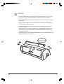
On the print head, the
“WARNING, Hot surface, Do not touch.” label is applied.
As the print head will be extremely hot after printing, please use caution.
v
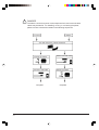
!
DANGER
The electric current from power cords, telephone lines, and communication
cables may be harmful. For installing, moving, or connecting the printer,
please connect or detach the cables in the following sequences.
To Connect
To Detach
Turn OFF the power of all the machines.
Connect the cables.
Detach from wall outlet
Connect to wall outlet
Detach the cables
Complete
vi
Complete
!
DANGER
• Never attempt to maintain or repair any parts other than those specified in
this manual. Fire or electric shock may result. If the printer performance is
diminished because cleaning or repair is required, please turn OFF the power
switch, unplug the power cord, and contact the store where the printer was pur
chased or a local service company.
• Do not lubricate or disassemble the printer. Fire or electric shock may result.
• Do not modify the printer. Fire or electric shock may result.
• Do not use the printer with any other voltage than that specified on the product.
Do not share one outlet with too many electric appliances. Fire or electric
shock may result.
• Do not use any other power cord than that specified for this printer. Do not use
a power cord attached to any other electric appliance. Fire or electric shock
hazard.
• Do not plug/unplug the power cord in/from the outlet with a wet hand.
It may cause an electric shock may result.
• Do not modify or let the power cord become damaged Do not place any heavy
objects on it. The power cord may get damaged and fire or electric shock may
result.
• If a telephone cable, communication cable, or TV antenna connection is included in the system unit installation, do not touch any of those cables during thunder and lightning storms.
• If the printer continues to be used in an abnormal condition, (when it is
overheated, smoke is coming out, unusual smell, etc.), fire or electric shock
may result. In any of these situations, immediately turn OFF the power switch,
unplug the power cord, and contact the store where the product was purchased
or a local service company.
• If any foreign objects (metal parts, water, other liquid, etc.) get inside the
printer, immediately turn OFF the power switch, unplug the power cord, and
contact the store where the product was purchased or a local service company.
If the printer is used in this condition, fire or electric shock mayresult.
• Should the printer be dropped or damaged, immediately turn OFF the power
switch, unplug the power cord, and contact the store where the product was
purchased or a local service company. If the printer continues to be used in
this condition, fire or electric shock hazard.
• Do not use any cables or connectors other than those specified for connection
with the optional equipment.
vii
!
CAUTION
• To unplug the power cord, always hold it by the plug to pull it. If you pull
the cord, it may get damaged and fire or electric shock may result.
• Do not expose the printer to high humidity or dust. Fire or electric shock
may result.
• Do not block the printer vent. If it is blocked or closed, the inside will be
come hot and a fire may result.
• The Print Head inside the printer will be hot immediately after printing.
Please be careful.
When opening or closing the Access Cover, installing the Ink-Ribbon Car
tridge, removing jammed paper, etc., please be especially careful not to
touch the Print Head.
Before putting the cover on the printer, first turn OFF the power switch and
wait until the printer cools down.
Heated Up!
viii
!
CAUTION
• When opening or closing the Access Cover, Front Cover, Cut Sheet
Guide, or Paper Stand, proceed gently and carefully.
• When the printer is not to be used for a long time, unplug the power cord.
• Ensure the printer is not subject to shocks or vibrations while it is printing.
ix
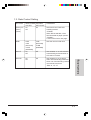
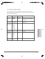
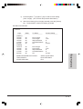
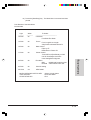
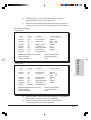
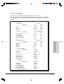
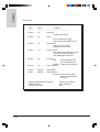
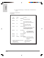
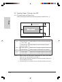
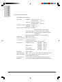
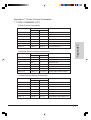
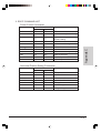
Features of the Printer
*1
x
ITEM
FUNCTION
Paper Size
3031, 3036
Cut Sheet paper
Fanfold Paper
3031N, 3036N
Cut Sheet paper
Fanfold Paper
FEATURE
76mm - 420mm
76mm - 406mm
Various size of paper can be
used.
3031, 3036
from post cards to A3-size
76mm - 297mm
76mm - 254mm
3031N, 3036N
from post cards to A4-size
Print Speed
Fast Draft(10cpi) 3036/36N: 336cps Various print speeds
3031/31N: 360cps
Draft (10cpi)
3036/36N: 250cps
3031/31N: 270cps
LQ (10cpi)
3036/36N: 75cps
NLQ
3031/31N: 68cps
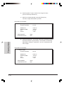
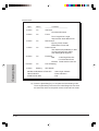
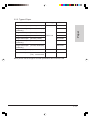
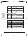
Character
Pitch
*1
10,12,15,17.1,20,24cpi, PS
Corresponds to various print
pitches
Font Style
Fast Draft, Draft,
LetterQuality (Gothic, Couirer,
Prestage, Presentor, Orator, Script)
Corresponds to various print
modifications.
Print
Style
Double-size(height, width),
These styles can be set by the
Quadruple-size,Bold, Subscript,
print commands.
Superscript,Ruled Line,Vertical-Writing
Reducation,Underline,Double-Strike
Operation
Panel
Start/Stop, Line Feed, Form Feed,
Font, Pitch, Micro-Up, Micro-Down,
User1/User2, 1st TR/2nd TR,
Alt function
Simple on finger operation
Paper Park
Holds Continuous Paper prior to
loading and after ejection.
Cut Sheet Paper can be use
without detaching the Continuous
Paper already set.
Front Loading
Loads Cut Sheet Paper.
Cut Sheet Paper can be inserted
conveniently from the front.
Tear Off
Tears along the Tear Bar line
Can easily tear Continuous Paper along the Tear Bar line.
Tractor
Double Tractor (Option)
By attaching the Option Tractor,
two types of Continuous Paper
can be set.
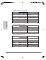
Multi-Sheet
Form
for 3036/36N: Original + 3 copies
for 3031/31N: Original + 5 copies
Forms of more than 1 original + 3/
5 copies can be used (depending
on the type of paper)by changing
the paper thickness adjustment.
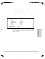
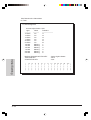
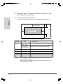
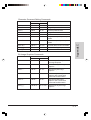
only for 3036/36N
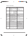
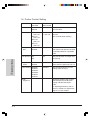
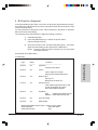
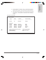
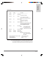
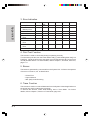
ITEM
FUNCTION
FEATURE
Emulation
IBM mode
3036/36N: IBM Proprinter X24, XL24
3031/31N: IBM Proprinter III, IIIXL
ESC/P mode
3036/36N: EPSON LQ850, LQ1050
3031/31N: EPSON FX850, FX1170
Emulation can be selected by the
set up mode.
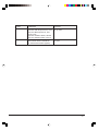
Interface
P/S2 Parallel Interface,
IEEE1284 Bi-direction Parallel I/F
RS-232C Serial Interafce (Option)
Can be connected to various system units.
xi
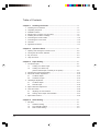
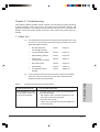
Table of Contents
Chapter 1. Installing the Printer ............................................................. 1-1
1. Checking the Accessories ............................................................................ 1-1
2. Unpacking the printer ................................................................................... 1-2
3.
4.
5.
6.
Installation Advice ........................................................................................ 1-3
Printer Parts, Locations, and Functions ....................................................... 1-4
Installing the Ink-ribbon Cartridge ................................................................ 1-6
Connecting the Printer Cable ....................................................................... 1-10
7. Connecting the Power Cord ......................................................................... 1-12
8. Test Print ..................................................................................................... 1-13
9. Application Software ..................................................................................... 1-17
Chapter 2. Operation Panel .................................................................... 2-1
1. Opening and Closing the Function Cover .................................................... 2-2
2. Turning the Alt Function ON/OFF ................................................................. 2-2
3. Key Functions ............................................................................................... 2-3
4. Lamp Functions ............................................................................................ 2-8
Chapter 3. Paper Setting ........................................................................ 3-1
1. Cut Sheet Paper ........................................................................................... 3-1
1.1. Loading Cut Sheet Paper ................................................................. 3-2
1.2. Loading Cut Sheet Paper .................................................................
(when Fanfold Paper is already in the printer) ................................. 3-5
2. Fanfold Form Feed Paper Setting ................................................................ 3-10
3. Print Start Position Adjustment ..................................................................... 3-15
3.1. Cut Sheet Paper ................................................................................ 3-15
3.2. Continuous Paper ............................................................................. 3-16
4. Left Margin Adjustment ................................................................................. 3-17
4.1. Cut Sheet Paper ................................................................................ 3-17
4.2. Fanfold Paper ................................................................................... 3-18
5. Paper Thickness Adjustment ........................................................................ 3-19
6. Tear-off Function .......................................................................................... 3-20
6.1. Adjusting the Tear Position ............................................................... 3-20
6.2. Tearing off the Paper at theTear Bar ................................................ 3-21
7. Paper Park Function ..................................................................................... 3-22
Chapter 4. Initial Setting ......................................................................... 4-1
1. Set Items ..................................................................................................... 4-1
1.1. Character Setting .............................................................................. 4-1
1.2. Form Handling Setting ...................................................................... 4-2
1.3. Data Control Setting .......................................................................... 4-3
xii
1.4.
1.5.
1.6.
2. Initial
2.1.
Printer Control Setting ...................................................................... 4-4
Emulation Setting .............................................................................. 4-6
Interface Option Setting .................................................................... 4-7
Setting Procedure ............................................................................... 4-8
Menu Configuration ........................................................................... 4-8
2.2. Setting Procedure ............................................................................. 4-9
3. Example of How to change the Initial Setting ............................................... 4-13
4. Bi-Direction Adjustment ................................................................................ 4-21
5. Print All Settings ........................................................................................... 4-27
6. Hex Dump Mode ........................................................................................... 4-28
Chapter 5. Troubleshooting ................................................................... 5-1
1. Check List ..................................................................................................... 5-1
2. Removing Jammed Paper ............................................................................ 5-11
2.1. FanfoldPaper .................................................................................... 5-11
2.2. Cut Sheet Paper ................................................................................ 5-12
Chapter 6. Consumables, Hardware Options, Maintenance................ 6-1
1. Consumables ................................................................................................ 6-1
1.1. Ink-ribbon Cartridge .......................................................................... 6-1
1.1.1. Replacing the Ink-ribbon Cartridge .............................................. 6-1
2. Hardware Options ......................................................................................... 6-2
2.1. Printer Cable ..................................................................................... 6-2
2.2. Auto Sheet Feeder (ASF) .................................................................. 6-2
2.2.1. Checking the Accessories .......................................................... 6-3
2.2.2. Installing the ASF ........................................................................ 6-4
2.2.3. Removing the ASF ...................................................................... 6-8
2.2.4. Cut Sheet Paper Handling in Auto Feed Mode .......................... 6-11
2.2.5. Cut Sheet Paper Handling in Manual Feed Mode ..................... 6-15
2.3. Optional Tractor ................................................................................ 6-18
2.3.1. Checking the Accessories .......................................................... 6-18
2.3.2.
2.3.3.
2.3.4.
2.3.5.
Installing the Optional Tractor ..................................................... 6-19
Removing the Optional Tractor ................................................... 6-22
Installing Fanfold Paper .............................................................. 6-24
Alternating Between Tractors ...................................................... 6-28
2.3.6. Handling Cut Sheet ..................................................................... 6-31
2.4. Serial Interface Option ...................................................................... 6-36
2.4.1. Checking the Accessories .......................................................... 6-36
2.4.2. Installing the Serial Interface Option ........................................... 6-37
2.4.3.
2.4.4.
2.4.5.
2.4.6.
Removing the Serial Interface Option ......................................... 6-41
Connecting the Serial Cable ........................................................ 6-44
Specification of the Serial Interface Option ................................. 6-46
Example of How to Change the Serial Interface Option Setting . 6-47
xiii
3. Cleaning ..................................................................................................... 6-54
3.1.
3.2.
Cleaning the Inside of the Printer ...................................................... 6-54
Cleaning the Cover ........................................................................... 6-54
Chapter 7. Paper ..................................................................................... 7-1
1. Remarks on Paper ........................................................................................ 7-1
2. Fanfold Paper ...............................................................................................
(when the built-in tractor or the Option Tractor is used) .............................. 7-2
2.1.
2.2.
2.3.
Printable Area and Paper Size .........................................................
(when printing is performed using the print head Pin No. 1) ............. 7-2
Type of Paper and Number of Copies in a Multi-sheet Form ........... 7-3
Conditions for Using Multi-sheet Forms ............................................ 7-4
2.4. About Perforated Lines ..................................................................... 7-6
2.5. When Fanfold Paper Runs Out ......................................................... 7-7
3. Cut Sheet Paper ........................................................................................... 7-8
3. 1. Feeding Paper Through the Cut Sheet Guide .................................. 7-8
3.1.1. Printable Area and Paper Size (when printing is performed ......
using the print head Pin No. 1) .................................................... 7-8
3.1.2. Types of Paper. ........................................................................... 7-9
3.2. Feeding Paper Through the ASF ...................................................... 7-10
3.2.1. Printable Area and Paper Size (when printing is performed ......
using the print head Pin No. 1) .................................................... 7-10
3.2.2. Types of Paper ............................................................................ 7-11
3.3. Feeding Paper Through Option Tractor or the ASF Manual Insert ...
Guide ................................................................................................. 7-12
3.3.1. Printable Area and Paper Size (when printing is performed ......
using the print head Pin No. 1) .................................................... 7-12
3.3.2. Types of Paper ............................................................................ 7-13
3.4. Conditions for Using Cut Sheet Paper .............................................. 7-14
3.5. About the Print Area for Cut Sheet Paper ......................................... 7-15
3.6. Remarks on Layout for Cut Sheet Paper .......................................... 7-15
4. Postcards ..................................................................................................... 7-16
4.1.
4.2.
Size and Standard ............................................................................. 7-16
Printable Area (when printing is performed using the print head ....
Pin No. 1) .......................................................................................... 7-17
5. Envelope (printable using manual feed) ....................................................... 7-21
5.1.
5.2.
5.3.
5.4.
Size ................................................................................................... 7-21
Boxes for Postal Zip Code Entry ....................................................... 7-23
Types of Envelopes and Paper Weight ............................................. 7-23
Printable Area (when printing is performed using the print head ....
Pin No. 1) .......................................................................................... 7-24
6. Label Paper (in Fanfold Paper Mode) ......................................................... 7-26
xiv
6.1.
Printable Area and Size (when printing is performed using the print
head Pin No. 1 ) ................................................................................ 7-26
6.2. Weight of Backing Paper ................................................................... 7-27
6.3. Paper Thickness ............................................................................... 7-27
7. Preprinting .................................................................................................... 7-28
7.1. Remarks on Preprinting .................................................................... 7-28
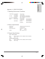
Appendix A.
Specifications .................................................................. A-1
1. Operating Environment Conditions .............................................................. A-1
2.
3.
4.
5.
Electric Specifications .................................................................................. A-1
Physical Specifications ................................................................................. A-1
Printing Specifications .................................................................................. A-2
Protective Function during Print Head warm-up ......................................... A-3
Appendix B.
Diagnostic Functions ...................................................... B-1
1. Initial Diagnostic Function ............................................................................ B-1
2.
3.
4.
5.
Operating Diagnostic Function ..................................................................... B-1
Error Indication ............................................................................................. B-2
Print Test Function ....................................................................................... B-2
Buzzer
..................................................................................................... B-2
6. Trace Function .............................................................................................. B-2
Appendix C.
Printer Control Commands ............................................ C-1
1. PPDS COMMAND LIST ............................................................................... C-1
2. ESC/P COMMAND LIST .............................................................................. C-5
xv
xvi
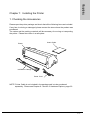
Installing
Chapter 1: Installing the Printer
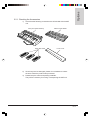
1. Checking the Accessories
Please open the printer package and check that all the following items are included.
If any item is missing or damaged, please contact the store where the product was
purchased.
The carton and the packing materials will be necessary for moving or transporting
the printer. Please store them in a safe place.
User's Guide
Printer
Ink-Ribbon Cartrige
Power Cord
NOTE: Printer Cable is not included in the package and is to be purchased
separately. Please see Chapter 6 - Section 2: Hardware Options, page 6-2.
1-1
Installing
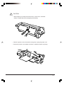
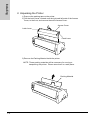
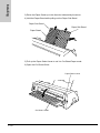
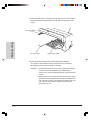
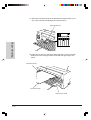
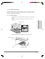
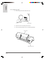
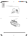
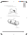
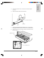
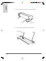
2. Unpacking the Printer
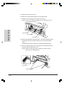
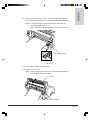
1) Remove the packing tape on the printer.
2) Pull the Latch Lever, located near the right and left ends of the Access
Cover, to the front, and remove the entire Access Cover.
Access Cover
Latch Lever
Latch Lever
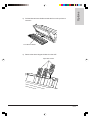
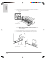
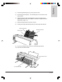
3) Remove the Packing Material inside the printer.
NOTE: Those packing materials will be necessary for moving or
transporting the printer. Please store them in a safe place.
Packing Material
1-2
Installing
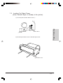
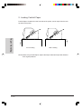
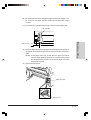
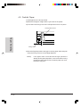
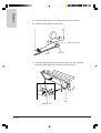
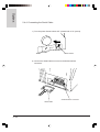
3. Installation Advice
!
CAUTION
Do not place the printer on an unstable surface.
It may fall and injure someone.
(1) Place the printer on a table surface as flat, level, and stable as possible,
where no vibrations may occur. On both sides of the printer, keep a free
space of at least 5 cm.
(2) Protect the printer from exessively high temperatures, keep it away from
heaters, radiators, direct sunlight, etc.
(3) Do not use the printer in environments with high humidity or with ecessive
dust containing oil and iron particles.
(4) Protect the printer from shocks, vibrations, strong magnetic fields, or
corrosive gases.
(5) Make sure that the mains power voltage matches the power voltage indicated
on the rating place. Do not use the printer, if the values do not match.
1-3
Installing
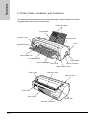
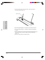
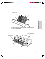
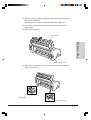
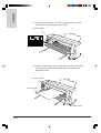
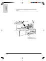
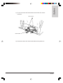
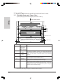
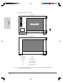
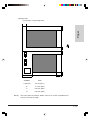
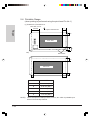
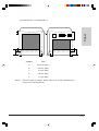
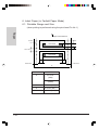
4. Printer Parts, Locations, and Functions
The following figures show the name of each printer part, and the table on the following page shows the functions of each part.
Paper Sub Stand
Paper Stand
Function Cover
Access Cover
Knob
Operation Panel
Paper Guide Left
Cut Sheet Guide
Power Switch
Paper Guide Right
Front Cover
Option Connector
Paper Select Lever
Latch Lever
Tear Bar Cutter
Gap Set Lever
Power Inlet
Rear Cover
Latch Lever
Interface Connector
1-4
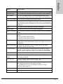
FUNCTIONS
Operation Panel
It indicates the printer status, and is used to change various settings.
Function Cover
Can be opened to change key functions and status of lamp indicators.
Paper Stand
It is used as a paper support for cut sheet paper already printed
when the option "paper exit to front" is set to OFF in the Initial Setting.
Paper Sub Stands
They are used for extending of the Paper Stand.
Access Cover
When the Ink-ribbon Cartridge is to be replaced or paper jams are to
be removed, this cover is detached to allow access to the related parts.
It also serves to protect operators from the mechanical movements of
the printer.
Knob
It is used to manually feed paper forward or backward.
Power Switch
It is used to turn ON or OFF the power of the printer.
Installing
NAME
Option Connectors They are used to connect an Auto Sheet Feeder (ASF) or the Optional
Tractor.
Paper Select Lever It is used to select the appropriate type of paper to be used in the
printer:
- Cut Sheet Paper (upper position)
- Continuous Paper (lower position)
Front Cover
It is opened when Continuous Paper is to be set. This cover is detached when an Auto Sheet Feeder (ASF) or the Option Tractor is to
be attached.
Paper Guide Right
By aligning the right edge of the Cut Sheet Paper to this guide,
an uneven feed can be prevented.
Cut Sheet Guide
It is opened for inserting Cut Sheet Paper and is used as a paper
support. It is also used as a support for post-print Cut Sheet Paper
when the option "paper exit to front" is set to ON in the Initial Setting.
Paper Guide Left
It is used to adjust the left margin of the Cut Sheet Paper.
Cover Release
By pulling this lever to the front, the latch is released and the Access
Lever
Cover can be opened.
Tear Bar Cutter
Continuous Paper will be cut at this position. By pressing the Tear Off
Key after printing, paper feeds up to this position.
Gap Set Lever
It is used to adjust the paper-pinching strength of the printer in accordance with the thickness of the paper to be used.
For the adjustment ranges, see Chapter 3, Section 5: Paper
thickness Adjust, page 3-19.
Interface Connector It is used to connect the cable to the system unit.
Power Inlet
It connects to the power cord.
1-5
Installing
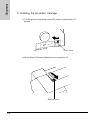
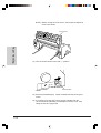
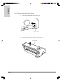
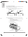
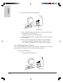
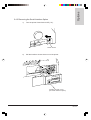
5. Installing the Ink-ribbon Cartridge
1) Turn the printer Power Switch to the OFF position (marked with a "O"
symbol).
Power Switch
2) Set the Paper Thickness Adjustment Lever to position "8" .
Gap Set Lever
1-6
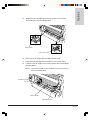
Installing
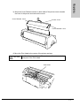
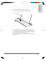
3) Move the Cover Release Levers on both sides of the printer cover towards
the front of the printer and remove the cover.
Cover Release Lever
Access Cover
Cover Release Lever
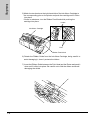
4) Move the Print Head to the center of the printer carriage.
!
CAUTION
The Print Head may be hot. Please be careful not to touch the
metal part of the Print Head.
Print Head
1-7
Installing
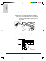
5) Match the two hooks on the right-hand side of the Ink-ribbon Cartridge to
the corresponding pins on the printer and push the cartridge until it clicks
into place.
If there is resistance, turn the Ribbon Feed Knob while pushing the
cartridge into place.
Hooks
Ink-ribbon Cartridge
Pins
Ribbon Feed Knob
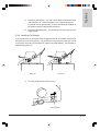
6) Detach the Ribbon Guide from the Ink-ribbon Cartridge, being careful to
avoid damaging it, since it protects the ribbon.
7) Insert the Ribbon Guide between the Print Head and the Platen and push it
down until it clicks into place. Be careful not to fold the ribbon and avoid
damaging the shield.
1-8
Installing
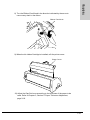
8) Turn the Ribbon Feed Knob in the direction indicated by the arrow to
remove any slack in the ribbon.
Ribbon Feed Knob
9) When the Ink-ribbon Cartridge is installed, refit the printer cover.
Printer Cover
10) Adjust the Gap Set Lever according to the thickness of the paper to be
used. Refer to Chapter 3, Section 5: Paper Thickness Adjustment,
page 3-19.
1-9
Installing
6. Connecting the Printer Cable
NOTE: Printer Cable is not a standard feature of the printer.
It must be purchased separately if you do not have one.
Refer to Chapter 6, Section 2: Hardware Options, page 6-2.
1) Turn the printer Power Switch OFF (marked with a "O" symbol).
Power Switch
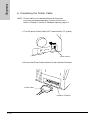
2) Connect the Printer Cable connector to the Interface Connector.
Printer Cable
Interface Connector
1-10
Installing
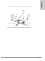
3) Fasten the Printer Cable connector by means of the two clips.
Clips
Printer Cable
4) Connect the other end of the Printer Cable to the system unit.
1-11
Installing
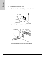
7. Connecting the Power Cord
1) Turn the printer Power Switch OFF (marked with a "O" symbol).
Power Switch
2) Connect the Power Cord to the Power Inlet.
Power Inlet
Power Cord
3) Insert the other end of the Power Cord into the wall outlet.
1-12
Installing
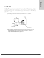
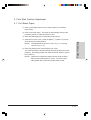
8. Test Print
The Test Print procedure is described for the use with Cut Sheet Paper. For the
installation procedure for Fanfold Paper, refer to Chapter 3, Section 2: Installing
Fanfold Paper, page 3-10. For details about paper, refer to Chapter 7: About Paper,
page 7-1.
1) Turn the printer Power Switch ON (marked with a " | " position).
Power Switch
2) Set the Paper Thickness Adjustment Lever according to the type and
thickness of the paper to be used. Refer to Chapter 3, Section 5:
Paper Thickness Adjustment, page 3-19.
1-13
Installing
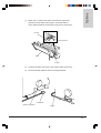
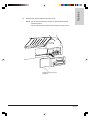
3) Raise the Paper Stand up in the direction indicated by the arrow.
4) Hold the Paper Stand while pulling out the Paper Sub Stand.
Paper Sub Stand
Paper Sub Stand
Paper Stand
5) Pull up the Paper Select Lever to set it to Cut Sheet Paper mode.
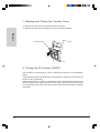
6) Open the Cut Sheet Guide.
Paper Select Lever
Cut Sheet Guide
1-14
Installing
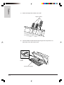
7) Match the left and right Paper Guides with the right paper edges.
8) Insert the paper into the printer until it stops against the inside roller. After
approximately 1 second the paper will be automatically fed to the print
position.
Left Paper Guide
Paper
Right Paper Guide
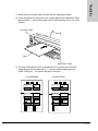
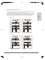
9) Turn the Power Switch OFF (marked with a "O" symbol), then turn the
Power Switch ON (marked with a " | " symbol) while holding down the
[LINE FEED] key. The printer will start a test print.
for 3036/3036N
Power
Ready
PaperOut
for 3031/3031N
Power
Ready
Start/Stop
Start/Stop
Alt
Alt
Line Feed
Tear Off
PaperOut
Form Feed
Park/Load
Line Feed
Tear Off
Font
Lock
User1
User2
Font
Lock
Courier
Prestage
Gothic
Presentor
Orator
Script
Draft
FastDraft
FastDraft
Draft
Gothic
Courier
Form Feed
Park/Load
User1
User2
1-15
Installing
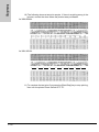
10) The following shows a test print sample. If there is anything wrong in the
printout, contact the store where the product was purchased.
for 3036/3036N:
for 3031/3031N:
1
2
3
4
5
6
7
8
9
11) To complete the test print, first press the [Start/Stop] key to stop printing,
then turn the printer Power Switch OFF "O".
1-16
Installing
9. Application Software
This section describes the Printer Type to be set in the application software. Select
one of the following printer drivers:
Epson Emulation Mode (factory default)
If the printer is configured for the Epson mode, select a following printer from
the printer selection menu of the application software.
3036
• Epson LQ1050
3031
• Epson FX1170
3036N
• Epson LQ850
3031N
• Epson FX850
IBM Emulation Mode
If the printer is configured for the IBM mode, select a following printer from
the printer selection menu of the application software.
3036
• IBM Proprinter XL24
3031
• IBM Proprinter III XL
3036N
• IBM Proprinter X24
3031N
• IBM Proprinter III
1-17
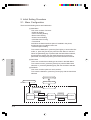
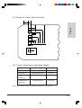
Chapter 2: Operation Panel
Panel
The Operation Panel consists of 6 function keys, with which the printer operating
modes can be set and 15/13 lamps to indicate the printer status.
The keys have different functions depending on the Function Cover OPEN/CLOSED
status and the Alt function ON/OFF status. Also the operation panel lamps show
different printer states depending on the Function Cover OPEN/CLOSE status.
for 3036/3036N:
P o w er
R e a dy
P a perO u t
S ta rt/Sto p
A lt
L in e Fe e d
Tea rO ff
Fo rm Fee d
P a rk/L o a d
Fo nt
L o ck
U s er1
U s er2
P o w er
Ready
P a pe r O u t
S ta rt/S to p
A lt
M ic ro
S e tU p
M ic ro
S e tLin e
P itc h
L o ck
1 st T R
2 n d TR
C o urier
O ra to r
10
20
P restig e
S cript
12
24
G o thic
D ra ft
15
PS
P resen tor
F as tD raft
17
Function Cover CLOSED Status
Function Cover OPEN Status
for 3031/3031N:
P o w er
R ea dy
P a p e rO u t
P ow er
A lt
A lt
F on t
L o ck
P ape rO u t
S ta rt/Stop
S ta rt/S to p
L in e F e e d
Te a r O ff
R ea d y
F o rm F e e d
P a rk /L o a d
U s e r1
U s e r2
F a s tD ra ft
D ra ft
G o th ic
C o ur ier
Function Cover CLOSED Status
M ic ro
S etU p
P itc h
L ock
M ic ro
S etLine
1 st T R
2 nd TR
10
20
12
PS
15
17
Function Cover OPEN Status
2-1
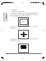
1. Opening and Closing the Function Cover
To open the Function Cover pull it down as shown in figure.
To close the Function Cover simply push it up in th reverse direction.
Panel
Function Cover
2. Turning the Alt Function ON/OFF
The Alt function is turned ON or OFF by pressing the [Alt] key on the Operation
Panel.
The Alt lamp is lit when the Alt function is ON (effective), and it turns off when the Alt
function is OFF (ineffective).
When the Alt function is OFF (i.e., the Alt lamp is off), the function keys perform the
function indicated with white characters on each key. When the Alt function is ON
(i.e., the Alt lamp is lit), the function keys perform the function indicated by the black
characters.
2-2
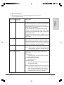
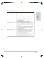
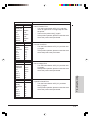
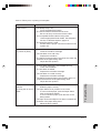
3. Key Functions
KEY NAME PRINTER
STATUS
FUNCTIONS
Start/Stop
On-Line/Off-Line
• Every time this key is pressed, the printer status
alternates between online (with the START/STOP
lamp lit) and offline (with the Ready lamp off).
• Pressing this key during printing, the printer goes
offline after the current line.
• In the Fanfold Paper mode and an out of paper
condition (i.e. the PAPER OUT lamp is lit), pressing this key the Fanfold Paper is fed up to the first
print position (TOF).
• Pressing this key after having cleared an error
condition (such as paper jam) switches the printer
back online.
Alt
Off-Line
• Pressing this key the Alt function will be
temporarily turned on (the Alt lamp is lit). After 1
second the Alt lamp will go off and the Alt function
will be deactivated. The [Tear Off], [Park/Load]
and [Font Lock] keys may then be used.
Line Feed
Off-Line
Panel
(1) When the Function Cover is closed and the Alt function is OFF
(i.e., the Alt lamp is off):
• Pressing this key feeds the paper forward 1 line.
NOTE: The line feed is performed according to the
current line feed value set in the Initial Setting or
by a software command.
Form Feed Off-Line
•The function of this key varies according to the
paper used:
Fanfold Paper:
Feeds the paper up to the first print position
(TOF) of the next page.
Cut Sheet (Manual Insertion):
Ejects the paper.
Cut Sheet (ASF):
The currently loaded sheet is ejected and the
next sheet is loaded.
NOTE: If loaded paper length does not correspond to the
paper length set by the page length setting command or by the Initial Setting in Fanfold Paper
mode, the paper will not be fed correctly to the
print start position (TOF) of the next page.
2-3
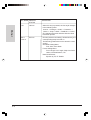
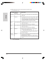
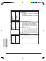
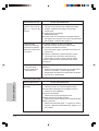
FUNCTIONS
Font
Off-Line
• When this key is pressed, the font style changes
in the following order.
Courier -> Prestige -> Gothic -> Presentor ->
Orator -> Script -> Draft -> FastDraft -> Courier
• The selection becomes effective after few lines
have been printed.
User 1
/ User 2
Off-Line
• This key selects user setting. Simultaneously, the
corresponding lamp is turned on.
The following parameters can be stored in a user
setting.
Character Setting Menu:
Font, Pitch, Zero Slash
Forms Setting Menu:
Form Length, Line Length, Skip Over Perforation,Cut Sheet Bottom, LPI
Data Control Menu:
Ejection by FF, FF Enable
Panel
KEY NAME PRINTER
STATUS
2-4
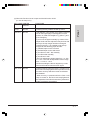
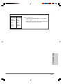
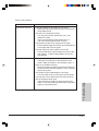
KEY NAME PRINTER
STATUS
FUNCTIONS
Tear Off
On-Line/Off-Line
• After printing is complete in the Fanfold Paper
mode, pressing this key the paper perforation is
moved to the tear bar position, according to the
current paper length.
• Pressing this key, when the paper perforation is in
tear-off position, the paper is moved to the first
print position (TOF).
• During the printout this key is disabled.
Park/Load
Off-Line
• This key is enabled only in Fanfold Paper mode.
• When the Fanfold Paper has already been loaded,
pressing this key the paper is moved to the park
position.
• When the Fanfold Paper is in the parking position,
pressing this key the paper is fed up to the first
printing position (TOF).
Font Lock
Off-Line
•Pressing this key when the Font Lock
lamp is off, the Font Lock lamp lights and the
Operation Panel functions and any selections
made via software are disabled.
•Pressing this key when the Font Lock
lamp is on, the Font Lock lamp turns off and the
selections made via software are enabled.
Panel
(2) When the Function Cover is closed and the Alt function is ON
(i.e., the Alt lamp is lit):
2-5
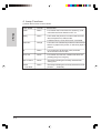
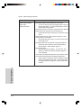
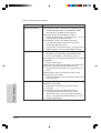
(3) When the Function Cover is open and the Alt function is OFF
(i.e. the Alt lamp is off.)
Panel
KEY NAME PRINTER
STATUS
FUNCTIONS
Start/Stop
On-Line/Off-Line
• Same as for (1) (Function Cover closed and Alt
lamp off).
Alt
Off-Line
• Pressing this key the Alt function will be
temporarily turned on (the Alt lamp is lit). After 1
second the Alt lamp will go off and the Alt function
will be deactivated. The [Set Up], [Set Line 1]
and [Pitch Lock] keys may then be used.
Micro ↑
On-Line/Off-Line
• Pressing this key the paper is fed forwards for
0.28 mm (1/90 in.).
• During the printout this key is disabled.
Micro ↓
On-Line/Off-Line
• Pressing this key the paper is fed backwards for
0.28 mm (1/90 in.).
• During the printout this key is disabled.
Pitch
Off-Line
• When this key is pressed, the character pitch
changes in the following order.
*1
10 -> 12 -> 15 -> 17 -> 20 -> 24 -> PS ->10
• The selection becomes effective after few lines
have been printed.
1st TR
/ 2nd TR
Off-Line
• This key is enabled only when the Optional Tractor
(upper tractor) is installed.
• Pressing this key, the selection toggles between
the standard (lower) tractor and the Optional (upper)
tractor.
*1
2-6
only for 3036/3036N
KEY NAME PRINTER
STATUS
FUNCTIONS
Set Up
Off-Line
• Pressing this key selects the Set Up menu.
Set Line 1
Off-Line
• The [SetLine 1] key allows you to set the 1st print
line on the logical page. The adjustment of the
position is made with the [Micro ↑], [Micro ↓] and
[Line Feed] key.
If you move the paper manually by means of the
Paper Knob and then adjust the first print line with
the keys, the top margin remains unchanged.
• Pressing this key, it is possible to set the top
margins for the following paper formats:
1) Fanfold Paper on the 1st tractor
2) Fanfold Paper fon the 2nd tractor
3) Cut Sheet in ASF - fed manually
4) Cut Sheet fed manually
5) Cut Sheet in ASF
• The TOF adjustment values range from +11 inch
to -1 inch. The Tear Off adjustment values range
from +1 inch to -1 inch.
Values exceeding the above ranges may not be
used, and if entered cause an error signal.
Pitch Lock
Off-Line
• Pressing this key when the Pitch Lock lamp is off,
the Pitch Lock lamp lights and the Operation Panel
functions and any selections made via software
are disabled.
• When this key is pressed while the Pitch Lock
lamp is turned on, the Pitch Lock lamp lights and
the Operation Panel functions and any selections
made via software are enabled.
Panel
(4) When the Function Cover is open and the Alt function is ON
(i.e. the Alt lamp is lit.)
2-7
4. Lamp Functions
(1) When the Function Cover is closed:
Panel
2-8
LAMP NAME
COLOR
FUNCTIONS
Power
Green
• It is lit when the Power Switch is set ON ("|") and
unlit when the Power Switch is OFF "O".
Ready
Green
• It is lit when the printer is in online mode and unlit
when the printer is in offline mode.
• It blinks when the Tear Off function is activated.
Paper Out
Orange
• It is lit when the Fanfold Paper Mode is selected and
there is no paper in the printer, or unlit when paper is
present.
Alt
Green
• It is lit when the Alt function is ON, and unlit
when the Alt function is OFF.
Font Lock
Green
• It is lit when the font lock condition has been set
pressing the [Font Lock] key.
User1 / User2
Green
• The lamp indicating the currently selected user
setting is lit.
Courier
.....Fast Draft
Green
• The lamp indicating the currently selected font is lit.
(Courier,.....,FastDraft)
LAMP NAME
COLOR
FUNCTIONS
Power
Green
• Same as for "(1) When the Function Cover is
closed."
Ready
Green
• Same as for "(1) When the Function Cover is
closed."
Paper Out
Orange
• Same as for "(1) When the Function Cover is
closed."
Alt
Green
• Same as for "(1) When the Function Cover is
closed."
Pitch Lock
Green
• It is lit when the font lock condition has been set
pressing the [Pitch Lock] key.
1st TR
Green
• It is lit when the standard (lower) tractor is selected
for Fanfold handling.
2nd TR
Green
• It is lit when the optional (upper) tractor is selected
for Fanfold handling.
10
Green
• The lamp indicating the currently selected pitch is
lit.
3036/3036N (10,12,15,17,20,24,PS)
3031/3031N (10,12,15,17,20,PS)
.....PS
Panel
(2) When the Function Cover is open:
2-9
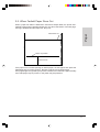
Chapter 3: Paper Handling
1. Cut Sheet Paper
Rear Out
Paper Handling
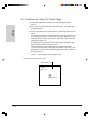
Cut Sheets are inserted from the front of the printer. The printed paper can be fed out
from the rear or the front side. Please refer to Chapter 4: Initial Setting, page 4-4.
Front Out
3-1
1.1. Loading Cut Sheet Paper
1) Turn the Power Switch of the printer ON " | ".
Paper Handling
Power Switch
2) Adjust the Paper Thickness Lever according to the type of paper to
be used. Refer to Section 5: Paper Thickness Adjustment,
page 3-19.
3) Raise the Paper Stand as shown in the following figure.
4) Hold the Paper Stand while pulling up the Paper Sub Stands.
Paper Sub Stand
Paper Sub Stand
Paper Stand
3-2
5) Set the Paper Select Lever to Cut Sheet Paper mode.
6) Open the Cut Sheet Guide.
Paper Handling
Paper Select Lever
Cut Sheet Guide
7) Set the left margin by moving the Left Paper Guide Left to the desired
position. (The "[A" mark indicates the standard print start position.)
Left Paper Guide
3-3
8) Place the Cut sheet on the paper stand aligning it to the Left Paper
Guide and match the Right Paper Guide with the right edge of the
paper.
Left Paper Guide
Paper Handling
Cut sheet paper
Right Paper Guide
9) Insert the paper between the Left and Right Paper Guides.
The paper is automatically fed to the first print line, the Ready
lamp lights and the printer is ready for printing.
NOTES: 1. If the PRINT lamp is not lit, the Cut Sheet Auto Insert
function has been disabled in the Initial Setting.
In this case, press the [Start/Stop] key to get the printer
ready.
2. If the paper is fed out to the rear side of the printer, about
30 sheets can be printed before the paper interferes with
the outcoming sheets. If the paper is ejected to the front
of the printer, each sheet must be removed before
printing a new one.
3-4
1.2. Loading Cut Sheet Paper
(when Fanfold Paper is already in the printer)
Paper Handling
1) Turn the printer Power Switch to ON " | ".
Power Switch
2) Set the Paper Select Lever to Fanfold Paper mode.
Paper Select Lever
3-5
3) Tear the fanfold paper at the tear off bar. See also Section 6:
Tear-off Function, page 3-20.
Fanfold Paper
Paper Handling
4) Press the [Start/Stop] key to change the printer status to off-line.
5) Press the [Park/Load] key. The paper is fed back to the parking
position.
6) Set the Gap Set Lever according to the thickness and the paper type
to be used. Refer to Section 5: Paper Thickness Adjustment,
page 3-19.
7) Raise the Paper Stand to the upper position.
3-6
8) Holding the Paper Stand while pulling up the Paper Sub Stand.
Paper Sub Stand
Paper Sub Stand
Paper Handling
Paper Stand
9) Push the Paper Select Lever up to set the Cut Sheet Paper mode.
10) Open the Cut Sheet Guide.
Paper Select Lever
Cut Sheet Guide
3-7
11) Move the Left Paper Guide to the desired left margin position. (The
"[A" mark indicates the standard print start position.)
Paper Guide Left
Paper Handling
12) Place the Cut sheet on the paper stand aligning it to the Left Paper
Guide and match the Right Paper Guide with the right edge of the
paper.
Left Paper Guide
Cut Sheet Paper
Right Paper Guide
3-8
13) Insert the paper between the Left and Right Paper Guides.
The paper is automatically fed to the print start position, then the
Ready lamp is lit and the printer is on-line.
Paper Handling
NOTES:1. If the PRINT lamp is not lit, the Cut Sheet Auto Insert
function has been disabled in the Initial Setting.
In this case, press the [Start/Stop] key to get the printer
ready.
2. If the paper is fed out to the rear side of the printer, about
30 sheets can be printed before the paper interferes with
the outcoming sheets. If the paper is ejected to the front
of the printer, each sheet must be removed before
printing a new one.
14) To print with Fanfold Paper again after the printing on a cut sheet,
push down the Paper Select Lever to set the Fanfold Paper mode
then press the [Park/Load] key to load the paper into the printer.
NOTE) When using Fanfold Paper, replace the Paper Stand and
Paper Sub Stand to the original positions.
3-9
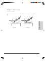
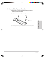
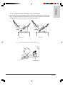
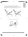
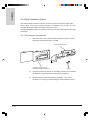
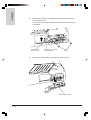
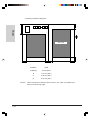
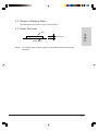
2. Loading Fanfold Paper
Fanfold Paper is loaded from the front side of the printer, and is output from the rear
top side of the printer.
Paper Handling
Front Loading
Rear Loading
NOTE) When using Fanfold Paper, replace the Paper Stand and Paper Sub Stand to
their original positions.
3-10
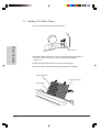
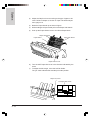
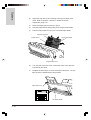
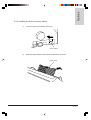
1) Adjust the Paper Thickness Adjust Lever according to the thickness
and type of used paper.
See also Section 5: Paper Thickness Adjustment, page 3-19.
2) Push down the Paper Select Lever to set the printer to Fanfold
Paper mode.
3) Open the Front Cover.
Paper Handling
Front Cover
Paper Select Lever
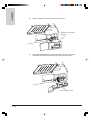
4) Raise the Fixing Levers of the Left and Right Sprockets (as shown in
figure), to free them.
Fixing Lever
Fixing Lever
3-11
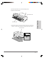
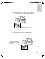
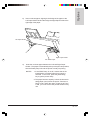
5) Open the two Sprocket covers.
6) Match the Left and Right Sprockets to the paper width.
7) Move the Tractor Guide to the center of the tractor.
NOTE) The Tractor Guide is installed only on the tractors of the
3031 and 3036 models.
Paper Handling
Sprocket cover
Tractor Guide
Sprocket cover
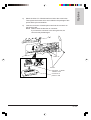
8) With the printing side of paper facing up, insert the left feeding holes
of the paper onto the Left Sprocket pins and close the Sprocket
cover.
NOTE) Make sure that the paper is inserted in loading direction.
9) Insert the right feeding holes of the paper onto the Right Sprocket
pins and close the Sprocket cover.
NOTE) Make sure that the paper is inserted correctly on both
sprockets, to avoid paper jam.
Sprocket Pin
Sprocket covers
3-12
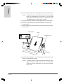
10) Move the two Sprockets to align the paper with the left margin. The
"[A" mark on the paper support shows the standard left margin
position.
11) Push down the Left Sprocket Fixing Lever to lock the Sprocket.
Paper Handling
Left Sprocket
Fixing Lever
12) Move the Right Sprocket to the right until the paper lies down flat on
the tractor and push down the Fixing Lever to lock the Sprocket in
place.
NOTE) If the paper does not lie flat and the right sprocket is
already at the rightmost position, remove the slack moving
the left sprocket to the left. Do not stretch paper too much,
because it may tear.
13) Close the Front Cover.
Right Sprocket
Fixing Lever
3-13
NOTE) Before closing the Front Cover, assure that the Sprocket
Covers are closed.
Front Cover
Paper Handling
14) Turn the Power Switch to the ON " | " position.
Power Switch
15) Press the [Start/Stop] key. Paper is loaded and the printer goes
on-line.
16) If you want to use the 2nd Tractor (option) together with the
1st Tractor Mode (standard), see Chapter 6, Section 2.3.5: Alter
nating the Tractors, page 6-28.
3-14
3. Print Start Position Adjustment
3.1. Cut Sheet Paper
1) Push up the Paper Select Lever to set the printer to Cut Sheet
Paper mode.
2) Insert a cut sheet paper. The paper is automatically fed up to the
print start position to make the printer on-line.
3) Press the [Start/Stop] key to make the printer off-line.
NOTE)
Paper Handling
4) Open the Function Cover, press the [Micro ↑ ] or [Micro ↓] keys to
set a desired print start position .
The adjustable range is from -25.4 mm (-1 in.) through
+279.4 mm (+11 in.).
5) Press the [Alt] key then press the [Set Line 1] key.
The current position is stored as the top print line position (print start
position). This setting is kept even after the Power Switch is turned
to the OFF "O" .
NOTE)
Please do not adjust the paper position using the Knob
before pressing the [Set Line 1] key. The correct print
start position will not be stored if the Knob is used.
3-15
3.2. Fanfold Paper
1) Push down the Paper Select Lever to set the Fanfold Paper mode.
2) Install the fanfold paper.
3) Press the [Park/Load] key. The paper is fed up to the print start
position.
4) Open the Function Cover, then press the [Micro ↑ ] or [Micro ↓] keys
to set a desired print start position.
NOTE)
Paper Handling
3-16
The adjustable range is from -25.4 mm (-1 in.) through
+279.4 mm (+11 in.).
5) Press the [Alt] key, then press the [Set Line 1] key.
The current position is stored as the top print line position (print
start position). This setting is kept even after the Power Switch is
turned to the OFF "O".
NOTE)
Please do not adjust the paper position using the Knob
before pressing the [Set Line 1] key. The correct print
start position will not be stored if the Knob is used.
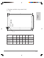
4. Left Margin Adjustment
This section describes how to adjust the left margin value. The "[A" mark on the left
side of the Cut Sheet Support and at the left bottom of the tractor unit gives a standard
reference for the first print start position.
4.1. Cut Sheet Paper
1) Place a sheet on the Cut Sheet Support, and align it to the Left Paper
Guide.
Paper Handling
2) Match the Left Paper Guide with the "[A" mark on the Cut Sheet
Support.
Left Paper Guide
3) Align the Right Paper Guide Right with the right paper margin.
Left Paper Guide
Paper
Right Paper Guide
3-17
4.2. Fanfold Paper
1) Install paper on the two sprockets.
2) Match the left paper margin with the "[A" mark on the printer.
3) Push down the Fixing Lever of the Left Sprocket to lock it in place.
Left Sprocket Cover
Paper Handling
Fixing Lever
4) Move the Right Sprocket to the right to remove paper slack and push
down the Fixing Lever to lock the Right Sprocket.
NOTE)
3-18
If the paper does not lie flat and the right sprocket is
already at the rightmost position, remove the slack moving
the left sprocket to the left. Do not stretch paper too much,
because it may tear.
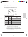
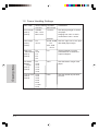
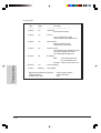
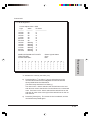
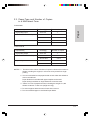
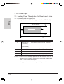
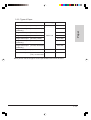
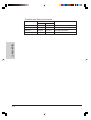
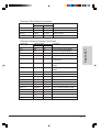
5. Paper Thickness Adjustment
To obtain optimum print quality, the gap between the Print Head and the Platen needs
to be adjusted according to the thickness of paper to be used.
Paper Handling
Gap Set Lever
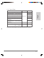
The following table shows the adjustable range:
Number of
Copies
Thickness
of Paper
Ream (Kg)
Paper Adjust Lever
Position
Original only
Thin
Normal
45-55
55-77
1
1-2
Thick
Original + 1
77-110
34/34
2
2-3
Original + 2
Original + 3
34/34/34
34/34/34/34
2-4
3-4
34/34/34/34/34
34/34/34/34/34/34
3-5
3-6
110
3
7-8
*1 Original + 4
*1 Original + 5
Post Card
Reserved
*1
Only for 3031
NOTES) 1. "Ream" is a unit of paper thickness, indicating the weight of 1,000 cut
sheets in size of 788 mm x 1091 mm (weight unit: Kg).
2. For paper of the original sheet only, Cut Sheet Paper of 45 Kg or
thicker or Fanfold Paper of 50 Kg or thicker can be used.
3. When the Paper Adjust Lever is set to a value larger than the appropriate value above, the printout appears scratchy and it shortens the lives
of the print head and the ink ribbon.
3-19
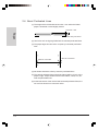
6. Tear-off Function
Paper Handling
This printer allows to feed paper up to the tear bar position by pressing the [Tear Off]
key (Tear Up). In this way you do not waste Fanfold paper when tearing it off.
After tearing the paper at the tear bar, the paper will be returned to the print start
position. (Tear Down)
This function is called "Tear Off" function.
If "Auto Tear Off" is enabled in setup menu, the printer operates as follows:
When there is no data to be printed in the receive buffer, the TOF conditions are met
and no data is sent from the PC, the printer automatically feeds up paper to the tear
bar position. (Auto Tear Up)
When data is received from the PC and the paper is in tear up state, the printer
automatically returnes the paper to the print start position. (Auto Tear Down)
This function is called "Auto Tear Off" function.
6.1. Adjusting the Tear Position
When Tear off function is executed, if the paper perforation does not match the tear
bar, adjust the Tear Position as follows:
NOTE) Before adjusting the Tear Position, adjust the page length of the used paper
in the Initial Setting or with the Page Length Setting command.
1) Install fanfold paper.
See Section 2: Fanfold paper handling, page 3-10 in this chapter.
2) Press the [Start/Stop] key to switch the printer online.
3) Press the [Form Feed] key to feed the paper for the length of one
page.
4) Press the [Tear Off] key to feed the paper up to the Tear Bar
Position.
5) Open the Function Cover. Then press the [Micro ↑] or [Micro ↓]
keys to move the paper perforation to the required Tear Bar Position.
NOTE) The adjustable range is ±25.4 mm (±1 in.).
6) Press the [Alt] key, then press the [Set Line 1] key. The current
position is stored as the Tear Bar Position. This position will be kept
even when the Power Switch is turned to the OFF "O" position.
NOTE) Do not adjust the paper position using the Knob before
pressing the [Set Line 1] key, or the correct position will
not be stored.
7) Close the Function Cover, then press the [Tear Off] key.
3-20
6.2. Tearing off the Paper at a Tear Bar
(1) When printing is complete, press the [Tear Off] key to feed the
paper up to the Tear Bar Position.
Paper Handling
(2) Using the Tear Bar, tear the paper at the perforation.
FanfoldPaper
(3) Press the [Tear Off] key to return the paper to the print start position.
3-21
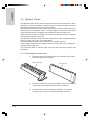
7. Paper Park Function
This printer allows to print on cut sheet paper without removing already loaded continuous paper from the tractor, but parking the fanfold paper.
1) Tear off the printed fanfold paper at the Tear Bar.
For tearing off the paper, see Section 6: Tear-off Function, page
3-20 in this chapter.
2) Press the [Park/Load] key. The fanfold paper is moved to the park
position and the Paper Out lamp is lit.
Paper Handling
3) When the fanfold paper is in the park position, load a cut sheet.
See Section 1: Loading Cut Sheets, page 3-1 in this section.
4) After the cut sheet has been printed and fed out, return the Paper
Stand and the Paper Sub Stand to their original positions.
5) Set the Paper Type Select Lever to Fanfold Paper Mode.
6) Press the [Park/Load] key. The fanfold paper is fed from the
tractor to the print start position, and the Paper Out lamp turns off.
7) Press the [Start/Stop] key to put the printer online.
3-22
Chapter 4. Initial Setting
This printer's default settings may be changed by using the Operation Panel.
The most recent settings are stored in memory even when the Power Switch is
turned OFF "O," and will be effective when the Power Switch is again turned ON "|".
In this chapter, the operation sequence from starting the initial value settings to ending them is called "Initial Setting Mode,", and the rest is called "Normal Print Mode."
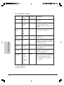
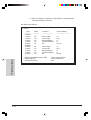
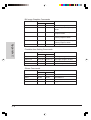
1. Set Items
In the Initial Setting Mode, the settings of the following items can be changed.
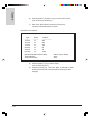
1.1. Character Settings
SET ITEM
SELECTABLE FACTORY
VALUES
SET VALUE
OVERVIEW
Font
(user1)
(user2)
FastDraft
Draft
Courier
Prestige
Gothic
Presentor
Orator
Script
Sets the font style for user1/2.
Zero Slash
(user1)
(user2)
*1
10
12
15
17
20
24
PS
Enable
Disable
*1
*1
*1
10
Sets the font pitch of User 1/2.
Disable
Sets slash or non slash of zero
for User 1/2
Initial Setting
Pitch
(User1)
(User2)
Courier
(3036/36N)
Draft
*1 (3031/31N)
*1
Only for 3036/3036N
4-1
1.2. Forms Handling Settings
SET ITEM
SELECTABLE FACTORY
VALUES
SET VALUE
OVERVIEW
Form Length
(user1)
(user2)
Variable
Min.: 1/6 in.
Max.: 60 in.
Sets the page length of continuous paper.
Ranging from 1/6 in. to 60 in.,
increments of 1/6 in. can be
11 inches
selected.
Initial Setting
4-2
Line Length
(user1)
(user2)
8 in.
13.6 in.
3031N, 3036N Sets the right limit of the print8 in.
able width (right margin).
3031, 3036
13.6 in.
Skip Over
Perforations
(user1)
(user2)
0 in.
1/2 in.
1 in.
2 in.
3 in.
0 in.
Selects whether or not the
perforated line of continuous
paper is skipped.
Cut Sheet
Bottom
margin
(user1)
(user2)
0 in.
1/8 in.
1/6 in.
1/4 in.
1/3 in.
1/2 in.
1/6 in.
Sets the bottom margin of the
paper.
Line per Inch
(user1)
(user2)
2 line
3 line
4 line
5 line
6 line
7.5 line
8 line
6 line
Sets the number of print lines
per inch.
SET ITEM
SELECTABLE FACTORY
VALUES
SET VALUE
OVERVIEW
Eject by FF
(user1)
(user2)
On
Off
On
Select the Form Feed code
handling method.
<Enable>
When DID is selected, a form
feed is treated as paper ejection.
<Disable>
A form feed is fed to next page.
Buffer
0 KB
4 KB
(3031/31N)
16 KB
(3036/36N)
4 KB
(3031/31N)
16 KB
(3036/36N)
Sets the receive buffer size.
Auto LF
On
Off
Off
Sets whether or not a line feed is
automatically performed when a
CR code is received.
Auto CR
On
Off
Off
Sets whether or not a carrige
return is automatically performed
when one of the following vertical
commands is received.
Initial Setting
1.3. Data Control Setting
-ESC Jn, LF, VT
4-3
1.4. Printer Control Setting
SET ITEM
Initial Setting
Auto TearOff Auto
Manual
Manual
Sets whether or not automatically
tear off enable
Front Eject
DID: Off
/ ASF: Off
DID: On
/ ASF: Off
DID: Off
/ ASF: On
DID: On
/ ASF: On
DID: Off
/ ASF: Off
Sets the cut sheet paper feed-out
direction.
(DID: manual paper feeding)
Ready on
DID
Enable
Disable
Enable
Sets whether or not automatically
enter print mode after the cut sheet
is manually loaded in unprintable
mode.
Uni-Dir Print
On
Off
Off
Sets print direction for single charcter printing.
Paper Out
Alarm
Enable
Disable
Enable
Sets whether or not to disable the
alarm when the paper has run out.
User Setting
Disable1
Enable1
Enable2
Disable2
Enable3
Enable4
Disable1
Sets the following item for user
settings.(refer to note1)
Bi-Di
Alignment
4-4
SELECTABLE FACTORY
OVERVIEW
VALUES
SET VALUE
Adjusts the position gap of ruled
lines between the two direction
printing in Bi-directional print
mode.
For adjusting directions, refer to
Section 4: Ruled Line Adjustment,
page 4-17 in this chapter.
User Setting
Disable 1
Enable 1
Enable 2
Disable 2
Enable 3
Enable 4
:
:
:
:
:
:
Both tractors depend on User 1 settings
TR1: User1, TR2: User2, Cut: User1
TR1: User1, TR2: User2, Cut: User2
Both tractors depend on User 1 settings
TR1: User1, TR2: User2, Cut: User1
TR1: User1, TR2: User2, Cut: User2
Initial Setting
Note 1)
4-5
1.5. Emulation Setting
Initial Setting
SET ITEM
SELECTABLE FACTORY
VALUES
SET VALUE
OVERVIEW
Emulation
IBM
EPSON
EPSON
Selects IBM emulation or EPSON
emulation.
AGM (IBM) *1 Enable
Disable
Disable
Sets wheter or not to select high
resolution graphic mode.
This settings also changes the line
density.
Code Page
(IBM)
437
850
860
863
865
437
Selects the code page in the resident font area in IBM mode.
Char. Set
(IBM)
Set1
Set2
Set1
Selects character set 1 or set 2
in IBM mode.
Pro-III
*2 On
Mode (IBM)
Off
Off
When this parameter is set on,
Proprinter III Emulation is selected.
When it is off, the ESC [ command
is partially supported.
20 Pitch
(IBM)
Enable
Selects 20 cpi or 12cpi when 12cpi
print mode is combined with condensed print mode.
*2 Enable
Disable
Table Set
(ESC/P)
Graphics
Italics
Graphics
Selects either Epson Extended
Graphic Character Table or
Italic Character Table
Int'l Char Set
(ESC/P)
USA
France
Germany
UK
Denmark
Sweden
Italy
Spain
USA
Selects a character assigned to the
code points: X'23",X'24",X'40"X'5B"
X'5C",X'5D",X'5E",X'60",X'7B",
X'7C",X'7D",X'7E" that is different
by countries.
*1 Only for 3036/36N
*2 Only for 3031/31N
4-6
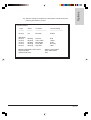
1.6. Interface Option Setting
SET ITEM
SELECTABLE FACTORY
VALUES
SET VALUE
OVERVIEW
RS-232C
Enable
Disable
Disable
Selects RS-232C interface option
when the option card is setting in
the printer.
Protcol
(RS-232C)
DTR
XON/XOFF
XON/XOFF
Selects DTR or Xon/Xoff protcol
of RS 232C
Trans. Rate
(RS-232C)
19200
9600
4800
2400
1200
600
300
9600
Selects Baud Rate of RS-232C
Data Length
(RS-232C)
7 Bits
8 Bits
8 Bits
Selects the data length of
RS-232C
Parity Bits
(RS-232C)
No Parity
Igrore
Odd
Even
Mark
Spc
No Parity
Selects the parity bits of RS-232C
Stop Bits
(RS-232C)
1 Bit
2 Bits
1 Bit
Selects the Stop bits of RS-232C
Initial Setting
This menu is enable when the interface optional card is installed in the printer.
For the installation of the interface option card, refer to Section 6: Serial Interface
Option, page 6-36 in chapter 6.
4-7
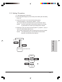
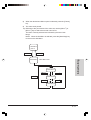
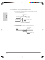
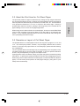
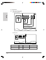
2. Initial Setting Procedure
2.1. Menu Configuration
The three Initial Setting menus are listed below:
(1) Main Menu
This menu consists of 6 items:
• Character Setting
• Forms Handling Setting
• Data Control Setting
• Printer Control Setting
• Initial Set Value Printing
• Trace Mode
And When the Serial Interface Option is installed in the printer,
the following item is added in this menu.
• Interface Option Setting
To access the Main Menu, press the [Set Up] key to enter Initial Set
mode, or, press the [Tractor] key when the Item Menu is selected.
When the [Start/Stop] key is pressed with the Main Menu selected,
the settings are stored, then the Initial Diagnostic functions are
performed, and finally the printer goes into the Normal Print Mode.
Initial Setting
(2) Item Menu
This menu contains items relating to each item in the Main Menu.
To access this menu, press the [Tractor] key with the Main Menu
selected, or, press the [Start/Stop] key with the Set Menu selected.
(3) Set Menu
This menu contains options for each set item.
To access the Set Menu, press the [Tractor] key with the Item Menu
selected.
Normal Print Mode
Normal Print Mode
Check Setup Value
Off Line
Set Up
Set Up Mode
Save Setup Value
Start/Stop
Tractor
Tractor
Main Menu
Start/Stop
4-8
Set Menu
Item Menu
Start/Stop
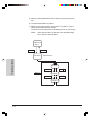
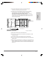
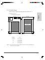
2.2. Setting Procedure
1) Load fanfold paper in the printer.
2) Press the [Start/Stop] key to switch the printer offline (with the Ready
lamp off).
3) Open the Function Cover and press the [Set Up] key.
( press the [Alt] key , then press the [Micro ↑] key )
The printer starts the Initial Set Mode and prints the Main Menu.
NOTE:
Once the Initial Set mode has been started, any remaining data that has not been processed will be cleared.
4) Referring to the print results, press the [Micro ↑] or [Micro ↓] key to
select the desired Main Menu items.
The currently selected items are indicated by the seven item lamps.
NOTE:
If the [Start/Stop] key is pressed with the Main Menu
selected, the Initial Set mode will end.
Normal Print Mode
Initial Setting
Off Line
Set Up
Start/Stop
Main Menu
Main Menu Print
Item 1
Micro ↓
Micro ↑
Item 2
Item X
4-9
5) When the desired Main Menu item is selected, press the [Tractor]
key.
6) The selected Sub Menu is printed.
7) Referring to the print results, use the [Micro ↑] or [Micro ↓] key to
select the desired Sub Menu settings.
The items currently selected are indicated by the seven item lamps.
NOTE:
When the Item Menu is selected, press the [Start/Stop]
key to return to the Main Menu.
Main Menu
Item X
Tractor
Start/Stop
Sub Menu
Sub Menu Print
Initial Setting
Sub Menu 1
Micro ↓
Micro ↓
Micro ↑
Sub Menu 2
Micro ↓
Micro ↑
Sub Menu X
4-10
8)
When the desired Item Menu option is selected, press the [Tractor]
key.
9)
The value set is printed.
10) Referring to the print results of the value set, use the [Micro ↑] or
[Micro ↓] key to select the set sub menu items.
The items currently selected are indicated by the seven item
lamps.
NOTE: When the Set Menu is selected, press the [Start/Stop] key
to return to the Sub Menu.
Sub Menu
Item X
Tractor
Start/Stop
Value Menu Print
Initial Setting
Value Menu
Value Menu 1
Micro ↓
Micro ↓
Micro ↑
Value Menu 2
Micro ↓
Micro ↑
Value Menu X
4-11
11) When the desired Set Value Item selected, press the [Tractor] key.
When the buzzer sounds, the selected item has been set, replacing
the previous setting.
NOTE: If you do not want to change the previous setting, press the
[Start/Stop] key.
12) After the new setting has been performed, the procedure returns to
the Sub Menu and prints it out.
13) Press the [Start/Stop] key to return to the Main Menu and print it out.
NOTE: To continue changing other items, repeat the above steps.
14) Press the [Start/Stop] key to complete the Initial Set Mode.
The changed settings are stored, the Initial Diagnostic functions
are executed, and then the printer returns to the Normal Print Mode.
NOTE: The changed settings are retained even after the Power
Switch has been turned OFF (O).
Initial Setting
4-12
3. Example of How to Change the Initial Setting
To change the form length setting of user 1 in the Main Menu's Forms Setting from 11
inches to 9.5 inches.
1)
Install fanfold paper in the printer.
2)
Press the [Start/Stop] key to switch the printer offline
(with the Ready lamp off).
3)
Open the Function Cover, and press the [Set Up] key. The printer
starts the Initial Set Mode and prints the Main Menu.
NOTE:
Once the Initial Set mode is selected, any non-processed
data will be cleared.
Print Results of the Main Menu
for 3036/36N:
>Setup Main Menu
12 Pitch
When
-----------On
On
To Select
----------------------------------------Character
Font/Pitch/Zro Slash
Forms
Initial Setting
Light
----------10 Pitch
Form Length/Line Length
Skip Pref/Cut Sheet Bottom/LPI
15 Pitch
On
Data Control
Eject by FF
Buffer/Auto LF/Auto CR
17 Pitch
On
Printer Control
Tear Off/Front Eject/Ready on DID
Uni-Dir Prnt/Paper Out Alarm
User Setting/Bi-Di Aligment
20 Pitch
On
Emulation
IBM
:AGM/Code Page/Char Set
EPSON :Table Set/Int'l Char Set
24 Pitch
On
Print All Setting
PS Pitch
On
HEX DUMP
MICRO UP/DOWN & PITCH KEY
TRACTOR KEY
START/STOP KEY
: Select Light & Status
: Enter Sub Menu
: End
4-13
for 3031/31N:
>Setup Main Menu
Light
----------10 Pitch
12 Pitch
When
-----------On
On
To Select
----------------------------------------Character
Font/Pitch/Zro Slash
Forms
Form Length/Line Length
Skip Pref/Cut Sheet Bottom/LPI
15 Pitch
On
Data Control
Eject by FF/FF Enable
Buffer/Auto LF/Auto CR
17 Pitch
On
Printer Control
Tear Off/Front Eject/Ready on DID
Uni-Dir Prnt/Paper Out Alarm
User Setting/Bi-Di Aligment
20 Pitch
On
Emulation
IBM
:Code Page/Char Set
Pro-III Mode/20 Pitch
EPSON :Table Set/Int'l Char Set
Initial Setting
4-14
PS Pitch
On
Print All Setting
10 Pitch
Blinking
HEX DUMP
MICRO UP/DOWN & PITCH KEY
TRACTOR KEY
START/STOP KEY
: Select Light & Status
: Enter Sub Menu
: End
4)
Press the [Micro ↑ ] or [Micro ↓] key to select Forms Setting
(Form Length). (The 12 Pitch lamp remains illuminated.)
5)
With Forms Setting (Form Length) selected, press the [Tractor]
key. The Sub Menu of theForms Setting is printed.
Sub Menu Print Results.
Light
----------(USER1)
10 Pitch
12 Pitch
15 Pitch
17 Pitch
20 Pitch
(USER2)
10 Pitch
12 Pitch
15 Pitch
17 Pitch
20 Pitch
When
------------
To Select
----------------------
Current Setting
--------------------------
On
On
On
On
On
Form Length
Line Length
Skip Perforation
Cut Sheet Bottom
LPI
11"
13.6"
0"
0"
6 Lines
On
On
On
On
On
Form Length
Line Length
Skip Perforation
Cut Sheet Bottom
LPI
11"
13.6"
0"
0"
6 Lines
MICRO UP/DOWN & PITCH KEY
TRACTOR KEY
START/STOP KEY
Initial Setting
>>Forms
: Select Light & Status
: Enter Value Menu
: End
4-15
6)
Press the [Micro ↓] key to select Form Length of User1.
(The 12 Pitch lamp remains lit.)
7)
With Form Length selected, press the [Tractor] key.
The Form Length Value Menu is printed.
Value Menu Print Results
>>>Page Length
Current Set Value
11 inch
MICRO UP
MICRO DOWN
ALT
PITCH
TRACTOR KEY
START/STOP KEY
8)
: Save
: Quit
Initial Setting
Press the [Pitch] key. The buzzer sounds to indicate that a setting
has been changed. Approximately 1 second later, the following
Value Menu is printed. At this time, "10 inch" is selected for the
Form Length.
Value Menu Print Results
>>>Page Length
Current Set Value
MICRO UP
MICRO DOWN
ALT
PITCH
TRACTOR KEY
START/STOP KEY
4-16
+1/6 inch
-1/6 inch
+1 inch
-1 inch
10 inch
+1/6 inch
-1/6 inch
+1 inch
-1 inch
: Save
: Quit
9)
Press the [Micro ↓] key three times consecutively.
Every time the key is pressed, the buzzer sounds to indicate that
the setting has been changed. Approximately 1 second later, the
following value Menu is printed. At this time, "9.5 inch" is selected
for the Form Length.
NOTE: The selected value is changed each time the key is
pressed.
Value Menu Print Results
>>>Page Length
Current Set Value
9 1/2 inch
MICRO UP
MICRO DOWN
ALT
PITCH
: Save
: Quit
Initial Setting
TRACTOR KEY
START/STOP KEY
+1/6 inch
-1/6 inch
+1 inch
-1 inch
10) Press the [Tractor] key. The Form Length of User1 is changed
to be 9.5 inches, and the buzzer sounds to indicate that the setting
has been changed.
4-17
11) After the change is complete, the Item Menu is restored and the
following Item Menu is printed.
Sub Menu Print Results.
>>Forms
Light
----------(USER1)
10 Pitch
12 Pitch
15 Pitch
17 Pitch
20 Pitch
(USER2)
10 Pitch
12 Pitch
15 Pitch
17 Pitch
20 Pitch
Initial Setting
4-18
When
------------
To Select
----------------------
Current Setting
--------------------------
On
On
On
On
On
Form Length
Line Length
Skip Perforation
Cut Sheet Bottom
LPI
11"
13.6"
0"
0"
6 Lines
On
On
On
On
On
Form Length
Line Length
Skip Perforation
Cut Sheet Bottom
LPI
11"
13.6"
0"
0"
6 Lines
MICRO UP/DOWN & PITCH KEY
TRACTOR KEY
START/STOP KEY
: Select Light & Status
: Enter Value Menu
: End
12) Press the [Start/Stop] key. The Main Menu is restored and then
printed.
Print Results of the Main Menu
for 3036/36N:
>Setup Main Menu
Light
----------10 Pitch
12 Pitch
When
-----------On
On
To Select
----------------------------------------Character
Font/Pitch/Zro Slash
Forms
15 Pitch
On
Data Control
Eject by FF
Buffer/Auto LF/Auto CR
17 Pitch
On
Printer Control
Tear Off/Front Eject/Ready on DID
Uni-Dir Prnt/Paper Out Alarm
User Setting/Bi-Di Aligment
20 Pitch
On
Emulation
IBM
:AGM/Code Page/Char Set
EPSON :Table Set/Int'l Char Set
24 Pitch
On
Print All Setting
PS Pitch
On
HEX DUMP
MICRO UP/DOWN & PITCH KEY
TRACTOR KEY
START/STOP KEY
Initial Setting
Form Length/Line Length
Skip Pref/Cut Sheet Bottom/LPI
: Select Light & Status
: Enter Sub Menu
: End
4-19
for 3031/31N:
>Setup Main Menu
Light
----------10 Pitch
12 Pitch
When
-----------On
On
To Select
----------------------------------------Character
Font/Pitch/Zro Slash
Forms
Form Length/Line Length
Skip Pref/Cut Sheet Bottom/LPI
15 Pitch
On
Data Control
Eject by FF/FF Enable
Buffer/Auto LF/Auto CR
17 Pitch
On
Printer Control
Tear Off/Front Eject/Ready on DID
Uni-Dir Prnt/Paper Out Alarm
User Setting/Bi-Di Aligment
20 Pitch
On
Emulation
IBM
:Code Page/Char Set
Pro-III Mode/20 Pitch
EPSON :Table Set/Int'l Char Set
Initial Setting
PS Pitch
On
Print All Setting
10 Pitch
Blinking
HEX DUMP
MICRO UP/DOWN & PITCH KEY
TRACTOR KEY
START/STOP KEY
: Select Light & Status
: Enter Sub Menu
: End
13) Press the [Start/Stop] key to complete the Initial Setting mode.
The changed settings are stored, the Initial Diagnostic functions
are executed, and then the printer returns to Normal Print mode.
4-20
4. Bi-Direction Alignment
In the Initial Setting mode, there is a function to adjust the gap between the respective ruled lines (vertical lines) by the left-to-right print and the right-to-left print in case
of bi-directional printing.
To enter Bi-Direction Alignment mode, select Bi-Direction Alignment in the Main
Menu's Printer Control Setting.
The following shows the Bi-Direction Alignment setting procedure:
1)
Install fanfold paper.
2)
Press the [Start/Stop] key to switch the printer offline
(with the Ready lamp off).
3)
Open the Function Cover, and press the [Set Up] key. The printer
starts the Initial Setting mode and prints the Main Menu.
NOTE: Once the Initial Set mode is selected, any non-processed
data will be cleared.
Print Results of the Main Menu
for 3036/36N:
>Setup Main Menu
12 Pitch
When
-----------On
On
To Select
----------------------------------------Character
Font/Pitch/Zro Slash
Initial Setting
Light
----------10 Pitch
Forms
Form Length/Line Length
Skip Pref/Cut Sheet Bottom/LPI
15 Pitch
On
Data Control
Eject by FF
Buffer/Auto LF/Auto CR
17 Pitch
On
Printer Control
Tear Off/Front Eject/Ready on DID
Uni-Dir Prnt/Paper Out Alarm
User Setting/Bi-Di Aligment
20 Pitch
On
Emulation
IBM
:AGM/Code Page/Char Set
EPSON :Table Set/Int'l Char Set
24 Pitch
On
Print All Setting
PS Pitch
On
HEX DUMP
MICRO UP/DOWN & PITCH KEY: Select Light & Status
TRACTOR KEY
: Enter Sub Menu
START/STOP KEY
: End
4-21
for 3031/31N:
>Setup Main Menu
Light
----------10 Pitch
12 Pitch
When
-----------On
On
To Select
----------------------------------------Character
Font/Pitch/Zro Slash
Forms
Form Length/Line Length
Skip Pref/Cut Sheet Bottom/LPI
15 Pitch
On
Data Control
Eject by FF/FF Enable
Buffer/Auto LF/Auto CR
17 Pitch
On
Printer Control
Tear Off/Front Eject/Ready on DID
Uni-Dir Prnt/Paper Out Alarm
User Setting/Bi-Di Aligment
20 Pitch
On
Emulation
IBM
:Code Page/Char Set
Pro-III Mode/20 Pitch
EPSON :Table Set/Int'l Char Set
Initial Setting
4-22
PS Pitch
On
Print All Setting
10 Pitch
Blinking
HEX DUMP
MICRO UP/DOWN & PITCH KEY
TRACTOR KEY
START/STOP KEY
: Select Light & Status
: Enter Sub Menu
: End
4)
Press the [Micro ↓] key to select Printer Control Setting
(Bi-Di Alignment). (The 17 Pitch lamp is lit.)
5)
With Print Control Setting (Bi-Di Alignment) selected, press the
[Tractor] key. The Printer Contarol Setting Sub Menu is printed.
Sub Menu Print Results.
for 3036/36N:
>>Printer Control
When
-----------On
On
15 Pitch
17 Pitch
20 Pitch
24 Pitch
PS Pitch
On
On
On
On
On
To Select
---------------------Auto Tear Off
Front Eject
Ready on DID
Uni-Dir Print
Paper Out Alarm
User Setting
Bi-Di Alignment
MICRO UP/DOWN & PITCH KEY
TRACTOR KEY
START/STOP KEY
Current Setting
-------------------------Manual
DID : Off
ASF : Off
Enable
On
Enable
Disable
: Select Light & Status
: Enter Value Menu
: End
Initial Setting
Light
----------10 Pitch
12 Pitch
for 3031/31N:
>>Printer Control
Light
----------10 Pitch
12 Pitch
15 Pitch
17 Pitch
20 Pitch
PS Pitch
10 Pitch
When
-----------On
On
On
On
On
On
Blinking
To Select
---------------------Auto Tear Off
Front Eject
Ready on DID
Uni-Dir Print
Paper Out Alarm
User Setting
Bi-Di Alignment
MICRO UP/DOWN & PITCH KEY
TRACTOR KEY
START/STOP KEY
Current Setting
-------------------------Manual
DID : Off
ASF : Off
Enable
On
Enable
Disable
: Select Light & Status
: Enter Value Menu
: End
6)
Press the [Micro ↑] key to select Bi-Di Alignment. (3036/36N: PS
Pitch lamp On, 3031/31N: 10 Pitch lamp Blinking)
7)
With Bi-Di Alignment selected, press the [Tractor] key.
The Bi-Di Alignment Value Menu is printed.
4-23
Print Results of the Value Menu
for T405:
>>>>Bi-Di Alignment
Current Adjust Value = XXX
Light
----------10 Pitch
12 Pitch
15 Pitch
17 Pitch
20 Pitch
24 Pitch
10 Pitch
12 Pitch
15 Pitch
17 Pitch
20 Pitch
24 Pitch
Initial Setting
4-24
When
-----------On
On
On
On
On
On
Blinking
Blinking
Blinking
Blinking
Blinking
Blinking
To Select
---------------------+1
+2
+3
+4
+5
+6
-1
-2
-3
-4
-5
-6
MICRO UP/DOWN & PITCH KEY
TRACTOR KEY
START/STOP KEY
*
|
|
|
|
-6
|
|
|
|
-5
|
|
|
|
-4
|
|
|
|
-3
|
|
|
|
-2
|
|
|
|
-1
|
|
|
|
: Select Light & Status
: Save
: Quit
0
|
|
|
|
+1
|
|
|
|
+2 +3 +4
|
|
|
|
|
|
|
|
|
|
|
|
+5
|
|
|
|
+6 *
|
|
|
|
|
|
|
|
for 3031/31N:
>>>>Bi-Di Alignment
Current Adjust Value = XXX
When
-----------On
On
On
On
On
On
Blinking
Blinking
Blinking
Blinking
Blinking
Blinking
To Select
---------------------+1
+2
+3
+4
+5
+6
-1
-2
-3
-4
-5
-6
MICRO UP/DOWN & PITCH KEY
TRACTOR KEY
START/STOP KEY
*
|
|
|
|
-6
|
|
|
|
-5
|
|
|
|
-4
|
|
|
|
-3
|
|
|
|
-2
|
|
|
|
-1
|
|
|
|
: Select Light & Status
: Save
: Quit
0
|
|
|
|
+1
|
|
|
|
+2 +3 +4
|
|
|
|
|
|
|
|
|
|
|
|
+5
|
|
|
|
Initial Setting
Light
----------10 Pitch
12 Pitch
15 Pitch
17 Pitch
20 Pitch
PS Pitch
10 Pitch
12 Pitch
15 Pitch
17 Pitch
20 Pitch
PS Pitch
+6 *
|
|
|
|
|
|
|
|
"0" indicates the currently set value (xxx).
8)
Press the [Micro ↑ ] or [Micro ↓] key to select the set of four
vertical lines that shows the straightest vertical line between
those printed below the Value Menu.
(The Pitch lamp should be lit or blinking.)
If an item on the + side is selected, the vertical lines on the 2nd
and 4th rows move to the left of the vertical lines on the 1st and 3rd
rows. If an item on the - side is selected the vertical lines on the
2nd and 4th rows move to the right of the vertical lines on the 1st
and 3rd rows.
9)
Press the [Tractor] key. The current choice is selected, and the
vertical lines are printed again.
4-25
10) If the change is satisfactory, press the [Start/Stop] key.
The buzzer sounds to indicate that the setting has been changed,
and the Printer Control Setting Sub Menu is restored.
NOTE: If further adjustment is necessary, repeat the above
procedure.
11) Press the [Start/Stop] key. The Main Menu is restored, and then
printed.
12) Press the [Start/Stop] key to complete the Initial Setting mode.
The changed settings are stored, the Initial Diagnostic functions
are executed, and then the printer returns to Normal Print mode.
Initial Setting
4-26
5. Print All Settings
In this mode, a list of all the current settings may be printed out.
The Initial Set Value Printout is started by selecting Print All Settings (24 Pitch lamp
On) in the Initial Value Setting Main Menu. After printing is complete, the Main Menu
is restored.
Print All Settings
Sub-Menu
---------------------------------------Font
Pitch
Zero Slash
>>Froms
Setting
User1
User2
--------------------Draft
Draft
10
10
Disable
Disable
Sub-Menu
---------------------------------------Form Length
Line Length
Skip Perforation
Cut Sheet Bottom
LPI
Setting
User1
User2
--------------------11"
11"
13.6"
13.6"
0"
0"
0"
0"
6 Line
6 Line
>>Data Contorl
Sub-Menu
---------------------------------------Eject by FF
Buffer
Auto LF
Auto CR
Setting
User1
User2
--------------------On
On
32KB
<<<
Off
<<<
Off
<<<
>>>Printer Control
Sub-Menu
---------------------------------------Tear Off
Front Eject
Ready on DID
Uni-Dir Print
Paper Out Alarm
User Setting
Setting
----------Manual
DID : Off
ASF : Off
Disable
Off
Enable
Disable
>>>Emulation
Sub-Menu
---------------------------------------Emulation
AGM(IBM)
Code Page (IBM)
Char Set (IBM)
Table Set(ESC/P)
Int'l Char Set(ESC/P)
Setting
----------ESC/P
Disable
437
Set1
Graphics
USA
Initial Setting
>>Character
4-27
6. Hex Dump Mode
In this mode, the data sent from the System Unit to the printer can be printed out with
the corresponding hexadecimal code.
The Hex Dump mode is started by selecting Hex Dump (PS Pitch lamp On) in the
Initial Value Setting Main Menu. This mode will be active until the Power Switch is
turned OFF "O."
NOTE: In the Trace Mode, data will be printed as soon as 1 line is ready.
When the receiving data is less than 1 line, it will be printed in Time-out
Print.
Initial Setting
4-28
Chapter 5. Troubleshooting
This chapter explains possible causes of printer errors and their remedies according
to their locations: errors may occur in the printer itself, hardware options, and
application software. First, attempt to find out the cause of the error , and when the
problem cannot be solved, please contact the store where the product was purchased.
1. Check List
(2)
Case 1.
The following list shows some common printer problems you may
encounter. If you find the case matching your problem, turn to the
applicable page for advice.
•
No response when
turning ON the power
Case 1
Page 5-1
•
Lamps indicate problem
Case 2
Page 5-2
•
Paper feeding problem
Case 3
Page 5-6
•
Fails to print,
or printing is incomplete.
Case 4
Page 5-7
•
Abnormal noises
Case 5
Page 5-8
•
ASF problem
Case 6
Page 5-9
•
The Optional Tractor
problem
Case 7
Page 5-10
If your problem cannot be solved, turn the printer Power Switch
OFF ("O"), disconnect the power cord, and contact the store
where the product was purchased.
No response when turning ON the power
PRINTER BEHAVIOR
The POWER lamp does
not illuminate, and there
is no printer response.
CAUSE AND REMEDIES
•
•
The plug of the power cord is loose or detached
from the wall outlet.
- Be certain to firmly connect the power cord to
the printer and to the wall outlet.
The wall outlet is faulty.
- Check by connecting other electric appliances
to the wall outlet.
Troubleshooting
(1)
5-1
Case 2. Error Indication of the lamps
PRINTER BEHAVIOR
Lamp
PowerOn
ReadyOn
PaperOut
Alt
Lock
User1
User2
Others
Lamp
PowerOn
ReadyOff
PaperOut
Alt
Lock
User1
User2
Others
Troubleshooting
5-2
Lamp
PowerOn
ReadyOff
PaperOut
Alt
Lock
User1
User2
Others
Lamp
PowerOn
Ready
paperOut
Alt
Lock
User1
User2
Others
Status
On
On
On
On
On
On
Status
Blinks
Off
Off
Blinks
Off
Off
Status
Blinks
Off
Blinks
Blinks
Blinks
Off
Status
Off
Blinks
Off
Blinks
Off
Off
Off
CAUSE AND REMEDIES
• Initial Diagnostic Test Error
- If this status is held for more than 10 seconds,
turn the Power Switch OFF ("O"), and then ON
("|") again. If the problem persists, contact the
store where the product was purchased.
• ROM/RAM Error
- Turn the Power Switch OFF ("O"), and then
ON ("|") again. If the problem persists, please
contact the store where the product was
purchased.
• Operation Panel Switch Error
- There is a problem with the Operation Panel
switches. Turn the Power Switch OFF ("O"),
and then ON ("|") again. If the problem
persists, please contact the store where the
product was purchased.
• NVRAM Error
- Turn the Power Switch OFF ("O"), and then ON
("|") again. If the problem persists,
please contact the store where the product was
purchased.
Lamp
PowerOn
ReadyOff
PaperOut
Alt
Lock
User1
User2
Others
Lamp
PowerOn
Ready
PaperOut
Alt
Lock
User1
User2
Others
Lamp
PowerOn
ReadyOff
PaperOut
Alt
Lock
User1
User2
Others
Lamp
PowerOff
Ready
paperOut
Alt
Lock
User1
User2
Others
Status
Blinks
Off
Blinks
Off
Blinks
Off
Status
Blinks
Blinks
Any
Any
Any
Any
Off
Status
Blinks
Blinks
Blinks
Off
Off
Off
Status
Off
Off
Off
Off
Off
Off
Off
CAUSE AND REMEDIES
• Home Position Error
- Turn the Power Switch OFF ("O"), and then
check for paper dust or foreign objects inside
the printer.
- Then turn the printer ON ("|") again.
If the problem persists, please contact the store
where the product was purchased.
• Control Card Error
- Turn the Power Switch OFF ("O") and then ON
("|") again.
If the problem persists, please contact the store
where the product was purchased.
• Drive Voltage Error
- Turn the Power Switch OFF ("O") and then ON
("|") again.
If the problem persists, please contact the store
where the product was purchased.
• Operation Panel Error
- Turn the Power Switch OFF ("O"), and then
ON ("|") again.
If the problem persists, please contact the store
where the product was purchased.
Troubleshooting
PHENOMENON
5-3
PRINTER BEHAVIOR
Troubleshooting
5-4
Lamp
Power
Ready
PaperOut
Alt
Lock
User1
User2
Others
Status
On
Off
Blinks
Off
Blinks
Blinks
Off
Off
Lamp
Power
Ready
PaperOut
Alt
Lock
User1
User2
Others
Status
On
Off
Blinks
Off
Any
Any
Any
Any
Lamp
Power
Ready
PaperOut
Alt
Lock
User1
User2
Others
Status
On
Off
Blinks
Blinks
Blinks
Off
Blinks
Off
CAUSE AND REMEDIES
• Font ROM Error
- Turn the Power Switch OFF ("O"), and then ON
("|") again.
If the problem persists, please contact the store
where the product was purchased.
One of the following errors has occurred:
• Paper Mode Alternation Error
- This error occurs, when the Paper Select Lever
position does not match the loaded paper.
Set the Paper Select Lever according to the
paper to be used, then press the [Start/Stop]
switch.
• Cut Sheet Feed-in/out Error
- This error occurs if paper cannot be loaded or
fed out in the Cut Sheet Paper Mode or when
the ASF is used. Remove the paper from inside
the printer, and press the [Start/Stop] switch.
If problems persist, please contact the store where the
product was purchased.
• Print Head Thermal Error
- Turn the Power Switch OFF ("O"), and then ON
("|") position again.
If the problem persists, please contact the store
where the product was purchased.
Lamp
PowerOn
Ready
paperOut
Alt
Lock
User1
User2
Others
Status
Off
Blinks
Blinks
Off
Blinks
Blinks
Off
CAUSE AND REMEDIES
• Option Tractor Error
- Turn the Power Switch OFF ("O"), and then
ON ("|") again.
If the problem persists, please contact the store
where the product was purchased.
Troubleshooting
PRINTER BEHAVIOR
5-5
Case 3. Paper feeding problems
PRINTER BEHAVIOR
Paper does not feed.
Paper tears.
Paper gets stuck.
Troubleshooting
5-6
CAUSE AND REMEDIES
• The Paper Select Lever position is not correct.
- To use cut sheets, push the Paper Select Lever to
the upper position. To use fanfold paper, push the
lever to the lower position.
• The feeding holes on the left or right side of the fanfold
paper are not fit properly over the tractor pins.
- Fit the holes over the tractor pins, and remove any
slack.
• The sprocket covers of the Tractor are open, or the
Fixing Lever is not locked.
- Close the Sprocket covers. Lock the Tractor with
the Fixing Lever.
• The paper does not correspond to the specifications.
- Use paper that conforms to the specifications
See Chapter 7: About Paper, page 7-1.
• Paper is jammed.
- Remove the jammed paper. To remove it, see
Section 2: Removing Jammed Paper, page 5-11
in this chapter.
• The Paper Thickness Adjustment Lever position does
not match the thickness of the paper being used.
- Set the Paper Thickness Lever to match the thickness of the paper being used. This is especially
important when thick paper or a multi-sheet form
is used.
Case 4. Fails to print, or printing is incomplete
CAUSE AND REMEDIES
Fails to Print.
• The Ready lamp is off.
- Press the [Start/Stop] switch.
• The Printer Cable is disconnected or loose.
- Be sure to firmly connect the Printer Cable.
• An incompatible Printer Cable is being used.
- Use an appropriate Printer Cable. See Chapter 6,
Section 2: Hardware Options, page 6-2.
• The wrong Emulation is used.
- Ensure that the proper command is sent from the
system unit.
No printout appears,
or printout is patchy.
• The Ink-ribbon Cartridge is not installed.
- Install an Ink-ribbon Cartridge.
• The Ink-ribbon is too old or dry.
- Replace the Ink-ribbon.
• The Paper Thickness Adjust Lever does not match the
thickness of the paper being used.
- Adjust the lever position.
Printout is incomplete.
• The Ink-ribbon Cartridge is not installed correctly.
- Check the installation.
• The Ink-ribbon is twisted.
- Replace the Ink-ribbon Cartridge.
• The Ink-ribbon is not fed correctly.
- Replace the Ink-ribbon Cartridge.
• The Paper Thickness Adjust Lever position does not
match the thickness of the paper being used.
- Adjust the lever position.
The print data rows are • The paper is not loaded correctly.
slanted.
- Install the paper correctly.
The line pitch is not con- • The Paper Select Lever position is not correct.
stant.
- To use cut sheet paper, push the Paper Select
Lever to the upper position.
To use continuous paper, push the lever to the
lower position.
• The Paper Thickness Adjust Lever does not match the
thickness of the paper being used.
- Adjust the lever position.
Troubleshooting
PRINTER BEHAVIOR
5-7
PRINTER BEHAVIOR
CAUSE AND REMEDIES
Wrong print start • The paper position is not set correctly.
position of the left-to- The "[A" mark indicates the standard print start
right or right-to-left
position. Match the left margin of the paper,
direction.
to this mark.
• The paper has is not straight.
- Reinstall the paper.
• The paper does not correspond to the specifications.
- Use paper that conforms to the given specifications
See Chapter 7: About Paper, page 7-1.
Irregular printing
• The Printer Cable is not firmly connected.
actions are performed.
- Be sure to firmly connect the Printer Cable.
Extra dots are printed. • The control command is incorrect.
Undesired characters
- Ensure that the proper command is sent from the
are printed.
system unit.
• The printer is affected by external electric noises.
- The noises may come from static electricity,
electric lamp circuits, or strong electric waves.
Please contact the store where the product was
purchased.
The print speed
becomes slow.
The print head stops
between lines.
• The print head protective function has not been
activated.
- When the print head becomes hot, this protective
function is activated. Once the print head
temperature decreases to normal limits, the protec
tive function is deactivated.
Case 5. Abnormal noises
Troubleshooting
5-8
PRINTER BEHAVIOR
Abnormal noises are
generated.
CAUSE AND REMEDIES
• The surface where the printer is placed is not flat.
- Place the printer on a flat and stable surface.
• The Ink-ribbon Cartridge is not installed correctly.
- Ensure correct installation.
• The knob is restrained.
- Remove any object touching the knob.
• Foreign objects are inside the printer.
- Remove any foreign objects from inside the printer.
• Paper is jammed.
- Remove the jammed paper. To remove it, refer to
Section 2: Removing Jammed Paper, page 5-11 in
this chapter.
Case 6. ASF problems
CAUSE AND REMEDIES
Paper does not feed.
• The Paper Select Lever position is not correct.
- When the ASF is used, push up the lever to the Cut
Sheet Paper Mode.
• The ASF is not attached correctly.
- Turn the printer Power Switch OFF ("O"), and
reattach the ASF.
Then, turn the printer Power Switch ON (" | ")
and check that the paper feeds correctly.
• The quantity of paper in the input bin is too large.
- Ensure that the paper level does not exceed the line
on the right side of the bin guide.
• The ASF Paper Set Lever position is incorrect.
- In Auto Feed Mode, set the Paper Set Lever to the
rear position. In Manual Feed Mode, set it to the
front position.
Paper jams.
• The paper exceeds specifications.
- Use paper according to the specifications of the
printer. Refer to Chapter 7: About Paper, page 7-1.
• Paper is not installed correctly.
- Remove the paper and fan thoroughly to make sure
the sheets are not sticking together. Then, insert the
paper in the printer.
• The quantity of the installed paper is too large.
- Do not exceed the line on the right of the bin guide.
• The Gap Set Lever position does not match the thick
ness of the paper being used.
- Adjust the lever according to the thickness of the
paper. This is especially important when using thick
paper or a multi-sheet form.
Troubleshooting
PRINTER BEHAVIOR
5-9
Case 7. Optional Tractor problems
PRINTER BEHAVIOR
Troubleshooting
5-10
CAUSE AND REMEDIES
Paper does not feed.
• The Optional Tractor is not set on the Operation Panel.
- Set the Optional Tractor on the Operation Panel.
See Chapter 2: Operation Panel, page 2-4.
• The Paper Select Lever position is incorrect.
- To use cut sheet paper, push the lever up. To use
Fanfold paper, push the lever down.
• The Optional Tractor is not attached correctly.
- Turn the printer Power Switch OFF ("O"), and
reinstall the Optional Tractor.
Then turn the Power Switch ON (" | ") and press the
[Park/Load] key to check if paper feeds correctly.
Paper gets jammed.
• The paper does not correspond to the specifications.
- Use paper according to the specifications of the
printer. See Chapter 7: About Paper, page 7-1.
• The Optional Tractor Manual Insert Guide is not closed
completely.
- Close it until it clicks.
• The holes on the left and right sides of the continuous
paper are not fit properly over the tractor pins.
- Fit the holes over the tractor pins, and remove any
slack.
• The Sprocket covers of a Tractor are open, or the
Fixing Lever is not locked.
- Close the Sprocket covers and lock the Tractor with
the Fixing Lever.
Paper feeds unevenly.
• The Gap Set Lever position does not match the
thickness of the paper.
- Adjust the lever position to match the paper
thickness.
• The Optional Tractor is not attached correctly.
- Turn the printer Power Switch OFF ("O") and
reinstall the tractor. Then turn the Power Switch
ON (" | "), and press the [Park/Load] key to check
if paper feeds evenly.
2. Removing Jammed Paper
2.1. Fanfold Paper
!
CAUTION
The print head may be hot. Please do not touch the metal
part of the print head.
NOTE: When the ASF or the Optional Tractor is attached, remove if necessary.
Proceed with the following steps with the printer placed on a flat and stable
surface.
1) Turn the printer Power Switch OFF ("O").
2) Tear off the fanfold paper.
3) Open the Access Cover, and move the print head to the leftmost or
rightmost position.
4) Open the Front Cover, open the Sprocket Covers on the left and right
Tractors, and remove the paper.
5) Gently pull the fanfold paper to the front until all the paper is
removed.
6) If any part comes out from the upper part of the printer, remove it.
7) Ensure that there are no torn paper parts remaining inside the printer,
then close the Access Cover.
If the problem persists, check again for any paper remaining inside the printer.
If the print test fails again, refer to Section 1: Check List, page 5-1 in this chapter.
Troubleshooting
8) To check that the jammed paper has been removed, perform a
print test. For the print test procedure see Chapter 1, Section 8:
Test Print, page 1-13.
5-11
2.2. Cut Sheet Paper
!
CAUTION
The print head may be hot. Please do not touch the metal
part of the print head.
NOTE: When the ASF or Optional Tractor is installed, remove if necessary.
Proceed with the following steps with the printer placed on a flat and stable
surface.
1) Turn the printer Power Switch OFF("O").
2) Open the Access Cover, and move the print head to the leftmost or
rightmost position.
3) If the paper comes out of the upper sied of the printer, pull it out
while turning the Knob to remove it.
4) Ensure that there are no torn paper parts remaining inside the printer,
then close the Access Cover.
5) Turn the Power Switch ON (" | ").
6) Press the [Start/Stop] key and check that the Paper Out lamp is
off and the Ready lamp is lit.
7) To check that the jammed paper has been removed, perform a
print test. For the print test procedure, see Chapter 1, Section 8:
Test Print, page 1-13.
If the problem persists, check again for any paper remaining inside the printer.
If the print test fails again, refer to Section 1: Check List, page 5-1 in this chapter.
Troubleshooting
5-12
Consumables,
Hardware
Options
Chapter 6.
Maintenance
Options,
1. Consumables
Consumables for this printer are Ink-ribbon Cartridges.
1.1. Ink-ribbon Cartridge
For the ink-ribbon, special ink is used to protect the print head.
Use only Compuprint original consumables
1.1.1. Replacing the Ink-ribbon Cartridge
This section describes the Ink-ribbon Cartridge replacement procedure.
!
CAUTION
The print head may be hot. Please do not touch the metal
part of the print head.
1) Turn the Power Switch OFF ("O").
2) Pull the Latch Levers at the left and right of the Access Cover
forward, and remove the Access Cover.
3) Move the print head to the center of the carriage.
4) Hold both sides of the Ink-ribbon Cartridge, and lift up to detach it.
5) Remove a new Ink-ribbon Cartridge from its protective wrapping,
and install it in the printer as described in Chapter 1,
Section 5: Installing the Ink-ribbon Cartridge, page 1-6.
After replacing the Ink-ribbon Cartridge, check that it is operating normally by
executing a print test. If the print test fails, check that the Ink-ribbon Cartridge has
been installed correctly.
NOTE: When discarding used old Ink-ribbon Cartridges, they must be disposed as
incombustible trash.
6-1
Options
2. Hardware Options
The Printer Cable, Auto Sheet Feeder (ASF), 2nd Tractor and Serial I/F are hardware
options for the printer.
2.1. Printer Cable
If a Printer Cable is needed, please order it from the store where the product was
purchased.
2.2. Auto Sheet Feeder (ASF)
The ASF allows automatic feeding of cut sheets or postcards into the printer. Even
with the ASF attached to the printer, you can still use fanfold paper or insert single cut
sheets manually.
The print mode using the ASF is called the "Auto Feed Mode," and the print mode in
which single cut sheets are inserted manually is called "Manual Insert Mode".
For further details on paper, see Chapter 7: About Paper, page 7-1.
If any problem arises when using the ASF, refer to Chapter 5: Troubleshooting, page
5-9.
If you need the ASF please order it to from the store where the product was
purchased.
6-2
Options
2.2.1. Checking the Accessories
1)
Check that the following accessories are all included with the ASF
unit.
ASF (Auto Sheet Feeder)
Paper Bin Guide
Manual Insert Guide
Front Cover
2)
Should any item be damaged, please do not hesitate to contact
the store where the product was purchased.
3)
Please keep the carton and packing materials.
They will be necessary for moving or transporting the ASF unit.
6-3
Options
2.2.2. Installing the ASF
1)
Turn the the printer Power Switch OFF ("O").
Power Switch
2)
Open the Front Cover halfway and remove it.
3)
Push up the Paper Select Lever to Cut Sheet Paper Mode.
Front Cover
Paper Select Lever
6-4
Options
4)
Match the "A" parts of the ASF unit with their respective
grooves on both sides of the printer, and press them in.
Then rotate the bottom of the ASF to secure it to the printer.
"A" part
Groove
ASF
"A" part
5)
Connect the ASF connector to the printer Option Connector.
6)
Secure the ASF cable as shown in the figure below.
Connector
Option Connector
Cable
6-5
Options
7)
Attach the Paper Bin Guides to the ASF.
Hopper Guides
8)
Insert the Manual Insert Guide along the grooves and push it in on
both sides of the ASF until it locks.
Groove
Manual Insert Guide
6-6
Options
9)
Install the Front Cover (which is included in the package as an
accessory) onto the printer.
Front Cover
6-7
Options
2.2.3. Removing the ASF
1) Turn the the printer Power Switch OFF ("O").
Power Switch
2) Open the Front Cover halfway, and remove it.
Front Cover
6-8
Options
3) Pull the Manual Insert Guide towards the front of the printer to
remove it.
Front Manual Guide
4) Remove the three Hopper Guides from the ASF.
Paper Bin Guides
6-9
Options
5) Unplug the ASF connector from the printer Option Connector.
6) Detach the ASF cable from the printer.
Option Connector
Connector
Cable
7) Hold down the Release Levers on both sides of the ASF, withdraw
the bottom part of the ASF to detach it from the printer.
ASF
Release Lever
6-10
Options
2.2.4. Cut Sheet Paper Handling in Auto Feed Mode
Cut sheet paper in Auto Feed Mode will automatically be loaded into the printer by the
ASF. The printout sheets may be fed out to the rear or front, depending on the Initial
Setting selection. Refer to Chapter 4: Initial Setting, page 4-3.
Rear Out
1)
Front Out
Turn the the printer Power Switch ON (" | ").
Power Switch
6-11
Options
2)
Adjust the Gap Set Lever according to the type of paper to be
used. Refer to Chapter 3, Section 5: Paper Thickness Adjustment, page 3-19.
3)
Raise the Paper Stand up as shown in figure.
4)
While holding the Paper Stand pull out the Paper Sub Stands.
5)
Push up the Paper Select Lever to Cut Sheet Paper Mode.
Paper Sub Stand
Paper Sub Stand
Paper Stand
Paper Select Lever
6)
Turn the ASF Paper Set Lever in the direction indicated by the
arrow.
7)
To adjust the left margin, move the Left Bin Guide.
The "[A" mark indicates the standard print start position.
Paper Set Lever
Left Paper Bin Guide
6-12
Options
8)
Push the Left and Right Separation Pad Levers in the direction
indicated by the arrow (except for the left edge bound multi-sheet
forms).
NOTE: Push these levers all the way in until they click twice.
If these levers are not pushed in the direction indicated by
the arrow, the paper may jam.
Right Separation Pad Lever
(Also push the Left Separation Pad Lever out)
9)
When using a left edge bound multi-sheet form, push the Left and
Right Separation Pad Levers in the direction indicated by the arrow.
NOTE: Push these levers in all way until they click twice.
If a left edge bound multi-sheet form is used without pushing in the levers, the paper may jam.
Right Separation Pad Lever
(Also push the Left Separation
Pad Lever out.)
6-13
Options
10) Insert cut sheet paper in the ASF aligning it to the Left Bin Guide.
NOTE: The paper should not exceed the mark inside the Right Bin
Guide. As a standard for your reference, up to 150 sheets
of 55Kg-paper in A4-size or smaller can be loaded, or up to
100 sheets if thicker or larger than A4 paper.
11) Align the Right Bin Guide to the right edge of the cut sheet paper.
12) Place the Paper Plate in the center between the Left and Right
Paper Guides.
13) Turn the Paper Set Lever of the ASF up in the direction indicated
by the arrow.
Right Hopper
Paper
Paper Set Lever
Left Hopper
14) Press the [Start/Stop] key. The Ready lamp is illuminated and the
printer is now ready for printing.
NOTE: The paper feed-out capacity is about 30 sheets for 55Kgpaper if the option "Feed-out to Rear" is ON. If the option
"Feed-out to Front" is selected, you must remove sheets
one by one.
6-14
Options
2.2.5. Cut Sheet Paper Handling in Manual Feed Mode
Cut sheet paper in Manual Feed Mode must be inserted through the opening near the
bottom of the ASF. The printout may be fed out to the front or rear of the printer in the
Initial Setting selection. Refer to Chapter 4: Initial Setting, page 4-3.
Rear Out
1)
Front Out
Turn the printer Power Switch of the printer ON (" | ").
Power Switch
6-15
Options
2)
Adjust the Gap Set Lever according to the type of paper to be
used. Refer to Chapter 3, Section 5: Paper Thickness
Adjustment, page 3-19.
3)
Raise the Paper Stand as shown in figure.
4)
Hold the Paper Stand, while pulling out the Paper Sub Stands.
5)
Push the Paper Select Lever up to Cut Sheet Paper Mode.
Paper Sub Stand
Paper Sub Stand
Paper Stand
Paper Select Lever
6)
Turn the ASF Paper Set Lever of the ASF down in the direction
indicated by the arrow.
7)
To adjust the left margin, move the Left Paper Guide Left. The "[A"
mark shows the standard print start position.
Paper Set Lever
Left Paper Guide
6-16
Options
8)
Insert cut sheet paper, aligning the left edge of the paper to the
Left Paper Guide Left and then align the Right Paper Guide to the
right edge of the paper.
Left Paper Guide
Right Paper Guide
Cut Sheet Paper
9)
Insert the cut sheet paper between the Left and Right Paper
Guides. The paper is automatically fed up to the print start position,
then the Ready lamp is lit and the printer is ready for printing.
NOTES:
1. If the PRINT lamp is not lit, it means that in the
Initial Setting Cut Sheet Paper Print Cancel is
selected. In this case, press the [Start/Stop]
key to get the printer ready.
2. The paper feed-out capacity is about 30 sheets for
55Kg-paper (ream) when the option "Feed-out to
Rear" is ON. When the option "Feed-out to Front"
is ON, you must remove the printed sheets one by
one.
6-17
Options
2.3. Optional Tractor
The Optional Tractor has the same functions as the built-in tractor the printer. When
the Optional Tractor is installed, two different types of continuous paper can be set
simultaneously and both can be selected for printing.
Alternating between the Optional Tractor and the built-in tractor is performed by the
[Tractor] key on the Operation Panel. The fanfold paper on one tractor unit can be
used for printing without unloading the fanfold paper on the other tractor unit.
When the Option Tractor is installed on the printer, you still can print with cut sheets
inserting them manually one by one.
The Optional Tractor print mode is the "2nd Tractor Mode." When using the stanrdard
tractor, the print mode is the "1st Tractor Mode."
For further details on paper, refer to Chapter 7: About Paper, page 7-1.
If any problem arises while the Optional Tractor is being used, refer to Chapter 5:
Troubleshooting, page 5-10.
If an Optional Tractor is needed, order it from the store where the product was
purchased.
2.3.1. Checking the Accessories
1)
When the carton of the Optional Tractor is opened, check that all
the following items are included:
Optional Tractor
6-18
Front Cover
2)
Should any items be missing or damaged, please do not hesitate
to contact the store where the product was purchased.
3)
Please keep the carton and packing materials. They will be
necessary for moving or transporting the Optional Tractor.
Options
2.3.2. Installing the Optional Tractor
1)
Turn the printer Power Switch OFF ("O").
Power Switch
2)
Open the Front Cover halfway, and remove it.
3)
Push the Paper Select Lever down to Fanfold Paper Mode.
Front Cover
Paper Select Lever
6-19
Options
4)
Insert the Optional Tractor ensuring that the top part run along the
"A" parts on both sides of the printer.
"A" part
Optional Tractor
NOTE: Before installing the Optional Tractor, move the Sprocket
Blocks of the printer at least 15 mm way from the
frame of the printer.
5)
Plug the Optional tractor connector into the printer connector.
6)
Secure the Option Tractor cable as shown in the figure below.
Connector
Cable
Option Connector
6-20
Options
7)
Install the Front Cover (contained in the package) onto the printer.
Front Cover
6-21
Options
2.3.3. Removing the Optional Tractor
1)
Turn the printer Power Switch OFF ("O").
Power Switch
2)
Open the Front Cover halfway, and remove it.
Front Cover
6-22
Unplug the Optional Tractor connector from the printer Option
Connector.
4)
Detach the Option Cable of from the printer.
Options
3)
Option Connector
Connector
Cable
5)
Push down the Optional Tractor Release Lever. The gears are
disengaged and the Release Lever returns to the upper position.
6)
Slightly lift it up and pull it forward to detach the Optional Tractor
from the printer.
Optional Tractor
Release Lever
6-23
Options
2.3.4. Installing the Fanfold Paper
When the Optional Tractor is installed, you can select alterately the two tractors
according to the paper used, as in the figures below.
NOTE: When the printer is printing, do not push down the Release Lever of the
Optional Tractor. A paper jam may result.
2nd Tractor Mode
1st Tractor Mode
NOTE: To use fanfold paper, return the Paper Stand and the Paper Sub Stands
to their original positions.
1)
Adjust the Gap Set Lever according to the paper type of paper to
be used. See Chapter 3, Section 5:
Paper Thickness Adjustment, page 3-19.
2)
Push down the Paper Select Lever to Fanfold Paper Mode.
3)
Open the Front Cover.
4)
Open the Manual Insert Guide.
Front Cover
Manual Insert Guide
6-24
Paper Select Lever
Options
5)
Raise the Left and Right Sprocket Fixing Levers up in the as
indicated by the arrow to release them.
Fixing Lever
Fixing Lever
6)
Open the Left and Right Sprocket Block Paper Holds.
7)
Adjust the Left and Right Sprocket Blocks to the paper width.
8)
Locate the Tractor Guide in the center between the Left and Right
Sprocket Blocks.
NOTE
The Tractor Guide is only installed on the tractors for the
3031 and 3036 models.
Sprocket covers
Tractor Guide
Sprocket covers
6-25
Options
9)
With the printing surface facing up, place the feeding holes on the
left edge of the paper over the pins of the Left Sprocket and
close the Sprocket cover.
NOTE: Place the paper parallel on both Sprockets.
10) Ensure that the feeding holes on the right edge of the paper fit
over the pins of the Right Sprocket, and close the Sprocket cover.
NOTE: To avoid paper jams, ensure that the paper is installed
correctly on both sides and placed over sprocket pins of
the same level.
Sprocket Pin
Sprocket covers
11) When the paper is installed, adjust the left margin moving the
Sprockets. The ["A" mark shows the standard print start position.
12) Push down the Fixing Lever of the Left Sprocket to lock it in
place.
Left Sprocket
Fixing Lever
6-26
Options
13) To remove slack from the paper, move the Right Sprocket Block,
then push down the Fixing Lever to lock the Right Sprocket Block.
NOTE: If the paper slack cannot be removed, adjust the Left
Sprocket Block position.
Be careful not to stretch the paper so much that it tears.
Right Sprocket Block
Fixing Lever
14) Push down the Manual Insert Guide
15) Close the Front Cover
NOTE: Before closing the Front Cover, ensure that the Sprocket
Block Paper Holds are closed.
Font Cover
Manual Insert Guide
6-27
Options
16) Turn the Power Switch ON ("|")position.
Power Switch
17) If the 2nd TRACTOR lamp is off, press the [Tractor] key to select
the Optional Tractor (2nd Tractor).
The paper feeds up to the print start position.
18) Press the [Start/Stop] key. The Ready lamp is lit and the printer is
ready to print.
19) If the 1st Tractor Mode (the built-in tractor) is to be used while
in the 2nd Tractor Mode (the Option Tractor), refers to Section
2.3.5: Alternating Between Tractors, page 6-28 in this chapter.
2.3.5. Alternating between Tractors
If the 1st Tractor Mode (for the built-in tractor) is to be used while the 2nd Tractor
Mode (Optional Tractor) is set, or vice versa, follow this procedure.
(1) In the 2nd Tractor Mode:
1)
Turn the Power Switch ON ("|").
Power Switch
6-28
Press the [Start/Stop] key to put the printer on line.
3)
Tear off the printed fanfold paper at the perforated line.
Options
2)
Fanfold Paper
4)
Press the [Tractor] key. The 1st Tractor Mode is selected and the
1st TR lamp is lit. The fanfold paper on the Optional Tractor is
moved back to the park position, and the fanfold paper installed on
the standard tractor is loaded into the printer.
5)
Press the [Start/Stop] key. The Ready lamp is lit and the printer is
ready to print.
6-29
Options
(2) In the 1st Tractor Mode:
1) Turn the Power Switch ON ("|").
Power Switch
2) Press the [Start/Stop] key to put the printer on-line.
3) Tear off the printed fanfold paper at the perforated line.
Fanfold Paper
6-30
Press the [Tractor] key. The 2nd Tractor Mode is selected and the
2nd TR lamp is lit. The fanfold paper on the standard tractor is
moved back to the park position, and the fanfold paper installed on
the Optional tractor is loaded into the printer.
5)
Press the [Start/Stop] key. The Ready lamp is lit and the printer is
ready to print.
Options
4)
2.3.6. Handling Cut Sheets
If you need to print on cut sheets when the Optional Tractor is installed, insert the cut
sheet from the front of the printer. The printed form can be fed out to the rear or front
of hte printer according to the selection made in the Initial Setting. See Chapter 4:
Initial Setting, page 4-3.
Rear Out
1)
Front Out
Turn the printer Power Switch ON ("|").
Power Switch
6-31
Options
2)
Push down the Paper Select Lever to Fanfold Paper Mode.
Paper Select Lever
3)
Tear off the printed fanfold paper at the perforated line.
Fanfold Paper
6-32
Press the [Start/Stop] key to put the printer online.
5)
Press the [Park/Load] key. The fanfold paper is moved back to the
park position.
6)
Adjust the Paper Thickness Adjustment Lever according to the
paper type to be used. See Chapter 3, Section 5: Paper Thickness
Adjustment, page 3-19.
7)
Raise the Paper Stand as shown in figure.
8)
Holding the Paper Stand while pulling out the Paper Sub Stands.
Options
4)
Paper Sub Stand
Paper Stand
9)
Paper Sub Stand
Push up the Paper Select Lever to Cut Sheet Paper Mode.
10) Open the Cut Sheet Guide.
Paper Select Lever
Cut Sheet Guide
6-33
Options
11) To adjust the left margin, move the Left Paper Guide. The "[A"
mark shows the standard print start position.
Left Paper Guide
12) Insert a cut sheet into the printer, aligning the left edge of the paper
to the Left Paper Guide and the right edge of the paper to the
Right Paper Guide.
Left Paper Guide
Cut Sheet Paper
Right Paper Guide
6-34
Options
13) Insert the cut sheet paper between the Left and Right Paper Guides.
The paper is automatically fed up to the print start position, then the
Ready lamp is lit, and the printer is ready to print.
NOTES:
1. If the Ready lamp is off, it means that Cut Sheet Paper
Print Cancel is selected in the Initial Setting. In this case,
press the [Start/Stop] key to put the printer on-line.
2. The paper feed-out capacity is about 30 sheets for 55Kgpaper (ream) when the option "Feed-out to Rear" is ON.
When the option "Feed-out to Front" is ON, you must
remove the printed sheets one by one.
14) If you need to print on fanfold paper after printing on a cut sheet,
push down the Paper Select Lever to Fanfold Paper Mode.
Then press the [Park/Load] key to load the fanfold paper.
NOTE: When using fanfold paper, be sure to return the Paper
Stand and the Paper Sub Stands to their original positions.
6-35
Options
2.4 Serial Interface Option
The Serial Interface Option is used to connect to the host computer by RS-232C
serial cable. The Serial Interface Option is installed in the printer, and the
corresponding parameters can be set in the Setup menu.
If the Serial Interface Option is needed, order it from the store where the product was
purchased.
2.4.1 Checking the Accessories
1)
When the carton of the Serial Interface Option is opened, check
that all the following items are included:
Serial Interface Card
Interface Access Cover
(for Serial Interface Oprion)
6-36
Screw
2)
Should any items be missing or damaged, please do not hesitate
to contact the store where the product was purchased.
3)
Please keep the carton and packing materials. They will be
necessary for moving or transporting the Serial Interface Option.
Options
2.4.2 Installing the Serial Interface Option
1)
Turn the printer Power Switch OFF ("O").
Power Switch
2)
Raise the Paper Stand in the direction indicated by the arrow.
Paper Stand
6-37
Options
3)
Pull the Interface Access Cover out of the printer.
Interface Access Cover
(Original)
4)
Insert the Serial Interface Card into the rear of Cover, then rotate
the bottom of Serial Interface Card to secure it to the printer.
Serial Interface Card
6-38
Match the holes "A" of Serial Interface Card to the screw holes.
Then tighten the Screws which are included in the package of this
option with the plus screwdriver.
6)
Insert the connector of Serial Option Card into the connector on
the printer's card.
NOTE Please check the direction of connector.
If you insert the connector in the wrong dirction, the
connector may be damaged.
Options
5)
Holes "A"
Screws
Connector of Serial
Interface Card
Connector on
printer's card
6-39
Options
7)
Insert the Interface Access Cover included in Serial Interface
Option.
NOTE Do not use the printer without the Interface Access Cover.
Interface Access Cover
(for Serial Interface Option)
6-40
Options
2.4.3 Removing the Serial Interface Option
1)
Turn the printer Power Switch OFF ("O").
Power Switch
2)
Pull the Interface Access Cover out of the printer.
Interface Access Cover
(for Serial Interface Oprion)
6-41
Options
3)
Remove the connector of Serial Option Card from the connector
on the printer's card.
Then remove two screws of setting the Serial Option Card by plus
screwdriver.
Connector on
printer's card
4)
Connector of Serial
Interface Card
Screw
Remove the Serial Interface Card from the rear of Cover.
Serial Interface Card
6-42
Options
5)
Reinsert the original Interface Access Cover .
NOTE Do not use the Interface Access Coverincluded in Serial
Interface Option.
Do not use the printer without the Interface Access Cover.
Interface Access Cover
(Original)
6-43
Options
2.4.4. Connecting the Serial Cable
1) Turn the printer Power Switch OFF (marked with a "O" symbol).
Power Switch
2) Connect the Serial Cable connector to the Serial Interface
Connector.
Serial Interface Connector
Serial Cable
6-44
Options
3) Fix the connector the fixed screws on both side of the serial
connector.
Fixed Screw
Serial Cable
4) Connect the other end of the Serial Cable to the system unit.
6-45
Options
2.4.5 Specification of the Serial Interface Option
1) PROTCOL
DTR, XON/XOFF
2) TRANSFER RATE
19200, 9600, 4800, 2400, 1200, 600, 300
3) DATA LENGTH
7 Bits, 8 Bits
4) PARITY BITS
Non, Ignore, Odd, Even
5) STOP BITS
1 Bit, 2Bits
6) PIN ASSIGNMENT
Pin No.
6-46
Signal
1
FG
Frame Ground
2
TXD
Transmit Data
3
RXD
Raceive Data
4
RTS
Request To Send
5
CTS
Clear To Send
6
DSR
Data Set Ready
7
SG
Signal Ground
20
DTR
Data Terminal Ready
Options
2.4.6 Example of How to Change the Serial Interface Option Setting
To change the transfer rate setting in the Main Menu's Serial Interface from 9600 to
19200.
1) Install the Serial Interface Option in the printer.
2) Install the fanfold paper in the printer.
3) Press the [Start/Stop] key to put the printer offline
(with the Ready lamp off).
4) Open the Function Cover, and press the [Set Up] key. The printer
starts the Initial Set Mode and prints the Main Menu.
Print Results of the Main Menu
for 3036/36N:
>Setup Main Menu
Light
----------10 Pitch
12 Pitch
When
-----------On
On
To Select
----------------------------------------Character
Font/Pitch/Zro Slash
Forms
Form Length/Line Length
Skip Pref/Cut Sheet Bottom/LPI
15 Pitch
On
Data Control
Eject by FF
Buffer/Auto LF/Auto CR
17 Pitch
On
Printer Control
Tear Off/Front Eject/Ready on DID
Uni-Dir Prnt/Paper Out Alarm
User Setting/Bi-Di Aligment
20 Pitch
On
24 Pitch
On
Emulation
IBM
:AGM/Code Page/Char Set
EPSON :Table Set/Int'l Char Set
Print All Setting
PS Pitch
On
HEX DUMP
10 Pitch
Blinking
Serial Interface
RS-232C :Protcol/Trans. Rate
Data Length/Parity Bits
Stop Bits
MICRO UP/DOWN & PITCH KEY
TRACTOR KEY
START/STOP KEY
: Select Light & Status
: Enter Sub Menu
: End
6-47
Options
for 3031/31N:
>Setup Main Menu
Light
----------10 Pitch
12 Pitch
When
-----------On
On
To Select
----------------------------------------Character
Font/Pitch/Zro Slash
Forms
Form Length/Line Length
Skip Pref/Cut Sheet Bottom/LPI
15 Pitch
On
Data Control
Eject by FF/FF Enable
Buffer/Auto LF/Auto CR
17 Pitch
On
Printer Control
Tear Off/Front Eject/Ready on DID
Uni-Dir Prnt/Paper Out Alarm
User Setting/Bi-Di Aligment
20 Pitch
On
Emulation
IBM
PS Pitch
On
:Code Page/Char Set
Pro-III Mode/20 Pitch
EPSON :Table Set/Int'l Char Set
Print All Setting
10 Pitch
Blinking
HEX DUMP
12 Pitch
Blinking
Serial Interface
RS-232C :Protcol/Trans. Rate
Data Length/Parity Bits
Stop Bits
MICRO UP/DOWN & PITCH KEY
TRACTOR KEY
START/STOP KEY
6-48
: Select Light & Status
: Enter Sub Menu
: End
Press the [Micro ↑] or [Micro ↓] key to select Serial Interface
Setting (Trans. Rate). (The 12 Pitch lamp remains blinking.)
5)
With Serial Interface Setting (Trans. Rate) selected, press the
[Tractor] key. The Sub Menu of theSerial Interface Setting is
printed.
Options
4)
Sub Menu Print Results.
>>Serial Interface
Light
-----------
When
------------
To Select
----------------------
Current Setting
--------------------------
10 Pitch
On
RS-232C
Enable
(RS-232C)
10 Pitch
12 Pitch
15 Pitch
17 Pitch
20 Pitch
Blinking
Blinking
Blinking
Blinking
Blinking
Protocol
Trans. Rate
Data length
Parity Bits
Stop Bits
DTR
9600
8 Bits
No Paity
1Bits
MICRO UP/DOWN & PITCH KEY
TRACTOR KEY
START/STOP KEY
: Select Light & Status
: Enter Value Menu
: End
6-49
Options
6)
Press the [Micro ↑] or [Micro ↓] key to select Trans. Rate .
(The 12 Pitch lamp is blinking.)
7)
With Trans. Rate selected, press the [Tractor] key.
The Trans. Rate Value Menu is printed.
Value Menu Print Results
>>>Trans. Rate (RS-232C)
Light
----------10 Pitch
12 Pitch
15 Pitch
17 Pitch
20 Pitch
24 Pitch
PS Pitch
When
-----------on
on
on
on
on
on
on
To Select
---------------------9600
4800
2400
1200
600
300
19200
MICRO UP/DOWN & PITCH KEY
TRACTOR KEY
START/STOP KEY
6-50
: Select Light & Status
: Save
: Quit
8)
Press the [Micro ↑] key to select 19200 .
(The 10 Pitch lamp is lit.)
9)
Press the [Tractor] key. The Trans. Rate is changed to 19200,
and the buzzer sounds to indicate that the setting has been
changed.
Options
10) After the change is complete, the Item Menu is restored and the
following Item Menu is printed.
>>Serial Interface
Light
-----------
When
------------
To Select
----------------------
Current Setting
--------------------------
10 Pitch
On
RS-232C
Enable
(RS-232C)
10 Pitch
12 Pitch
15 Pitch
17 Pitch
20 Pitch
Blinking
Blinking
Blinking
Blinking
Blinking
Protocol
Trans. Rate
Data length
Parity Bits
Stop Bits
DTR
19200
8 Bits
No Paity
1Bits
MICRO UP/DOWN & PITCH KEY
TRACTOR KEY
START/STOP KEY
: Select Light & Status
: Enter Value Menu
: End
6-51
Options
11) Press the [Start/Stop] key. The Main Menu is restored and then
printed.
Print Results of the Main Menu
for 3036/36N:
>Setup Main Menu
Light
----------10 Pitch
12 Pitch
When
-----------On
On
To Select
----------------------------------------Character
Font/Pitch/Zro Slash
Forms
Form Length/Line Length
Skip Pref/Cut Sheet Bottom/LPI
15 Pitch
On
Data Control
Eject by FF/FF Enable
Buffer/Auto LF/Auto CR
17 Pitch
On
Printer Control
Tear Off/Front Eject/Ready on DID
Uni-Dir Prnt/Paper Out Alarm
User Setting/Bi-Di Aligment
20 Pitch
On
Emulation
IBM
24 Pitch
On
:Code Page/Char Set
Pro-III Mode/20 Pitch
EPSON :Table Set/Int'l Char Set
Print All Setting
PS Pitch
On
HEX DUMP
10 Pitch
Blinking
Serial Interface
RS-232C :Protcol/Trans. Rate
Data Length/Parity Bits
Stop Bits
MICRO UP/DOWN & PITCH KEY
TRACTOR KEY
START/STOP KEY
6-52
: Select Light & Status
: Enter Sub Menu
: End
Options
for 3031/31N:
>Setup Main Menu
Light
----------10 Pitch
12 Pitch
When
-----------On
On
To Select
----------------------------------------Character
Font/Pitch/Zro Slash
Forms
Form Length/Line Length
Skip Pref/Cut Sheet Bottom/LPI
15 Pitch
On
Data Control
Eject by FF/FF Enable
Buffer/Auto LF/Auto CR
17 Pitch
On
Printer Control
Tear Off/Front Eject/Ready on DID
Uni-Dir Prnt/Paper Out Alarm
User Setting/Bi-Di Aligment
20 Pitch
On
Emulation
IBM
PS Pitch
On
:Code Page/Char Set
Pro-III Mode/20 Pitch
EPSON :Table Set/Int'l Char Set
Print All Setting
10 Pitch
Blinking
HEX DUMP
12 Pitch
Blinking
Serial Interface
RS-232C :Protcol/Trans. Rate
Data Length/Parity Bits
Stop Bits
MICRO UP/DOWN & PITCH KEY
TRACTOR KEY
START/STOP KEY
: Select Light & Status
: Enter Sub Menu
: End
12) Press the [Start/Stop] key to complete the Initial Setting mode.
The changed settings are stored, the Initial Diagnostic functions
are executed, and then the printer returns to Normal Print mode.
6-53
Options
3. Cleaning
To maintain the printer in good condition, please perform periodical cleaning every 2
or 3 months.
Before cleaning, proceed as follows.
!
CAUTION
The print head may be hot immediately after printing.
Wait until it cools down (about 15 minutes) before cleaning.
1) Turn the printer Power Switch OFF ("O").
2) Unplug the Power Cord.
3.1. Cleaning the Inside of the Printer
Use a soft brush to remove dust, ribbon pieces, paper bits, etc.
3.2. Cleaning the Cover
Use a soft cloth moistened with water and a mild detergent to wipe dust, smudges,
and stains off of the printer's cover.
Do not use any volatile chemicals (benzine, paint thinner, alcohol, etc.).
Such chemicals may damage the cover surface.
6-54
Chapter 7. Paper
This chapter describes paper that can be used with this printer.
Ensure that all paper used is free of tears, dust, wrinkles, and curled or bent edges.
1. Remarks on Paper
Paper
If a large amount of paper is to be printed, be sure to perform a test print. Check that
the paper feeds correctly and the printout is clear.
Types of paper that should not be used with the printer include:
Paper with uneven thickness;
Paper with exposed or partially peeled-off adhesive labels;
Paper with metallic parts;
Paper with cut-outs or windows (including binding holes);
Paper with engravings;
Folded paper;
Paper with folded or torn edges;
Extremely thin or thick paper (which exceeds paper specifications);
NOTE: When using a multi-sheet form, a maximum of 5 copies
including the original is normally acceptable. This obviously
depends also on the paper weight (thickness).
Paper thicker than 0.35 mm cannot be used.
Particularly small or large paper (exceeding the paper specifications);
Warped paper;
NOTE: Do not expose paper to high temperatures or humidity, to
avoid curling or wrinkling.
Before using curled paper, it must be bend to straighten it.
Use white high-quality paper (recycled paper can also be used).
If paper with the following characteristics is to be used, be sure to perform sufficient
print tests before using:
• Label Paper (Labels may peel off when the paper is moved backwards.)
NOTE: Do not print on the label support paper or across the border line
between the support and the label.
• Multi-sheet Form Paper (no-needle stapling)
• Postcards or envelopes which exceed the paper specifications
7-1
2. Fanfold Paper (when the standard or the Optional Tractor is used)
2.1. Printable Area and Paper Size
(when printing is performed using the print head Pin No. 1)
Paper Feed Direction
Paper
D±2
Perforated Line
E
B
C
Printable Range
12.7 ± 0.1
6.35
∅ 4 ± 0.2
Sprocket Hole
F
Perforated Line
6.35 ± 0.3
6.35
6.35 ± 0.3
A
(Unit:mm)
SYMBOL
SIZE
A
3 to 16 in.
(3036, 3031)
3 to 10 in.
(3036 N, 3031N)
B
6.35 mm
(Min.)
C
6.35 mm
(Min.)
D
6.35 mm
This is the top allowance for auto-feeding (the distance from the
top of the paper to the print head Pin No. 1)
E
6.35 mm
To avoid print smudges, caused by the horizontal perforated lines,
printing should not be attempted within this range.
F
6.35 mm
To avoid print smudges, caused by the horizontal perforated lines,
printing should not be performed within this range. Please also
note that for the F range, it is advisable not to print in a range of
about 20 mm from the lower margin.
NOTE:
CONTENTS
Paper Width
To avoid print smudges, caused by the vertical perforated lines
and the feeding holes, printing should not be performed within this
range. For best results, a width of at least 12 mm should be
assured.
3031, 3036; When using 16-inch paper, the "B" value is about 13 mm (Min.).
3031N, 3036N; When using 10-inch paper, the "B" value is about 13 mm (Min.).
7-2
2.2. Paper-Type and Number of Copies
in a Multi-sheet Form
for 3036/36N
Ream(Kg)
High-quality Paper
43 to 135
1
One-time Back-carbon Paper
32.5 to 38.5
4
32.5 to 48.5
2 to 3
32.5 to 38.5
4
34 to 55
2 to 3
Impact Paper
Number of Copies
Paper
PaperQuality
for 3031/3031N
PaperQuality
Ream(Kg)
High-quality Paper
43 to 135
1
One-time Back-carbon Paper
32.5 to 38.5
4 to 6
32.5 to 48.5
2 to 3
32.5 to 38.5
4 to 6
34 to 55
2 to 3
Impact Paper
Number of Copies
NOTES: 1. The value in the column "Number of Copies" indicates the number of
sheets, including the original, in a form set to be printed in a single
printing.
2. It is reccommended to use paper binded on both sides with adhesive
dots or etched lines.
Paper binded on both sides with paper staples can be used.
Paper having both sides or single sides free cannot be used.
3. "Ream" is a unit of paper thickness, indicating the weight of 1,000
sheets at 788 mm x 1091 mm (weight unit: Kg).
4. Do not use paper with thickness of more than 0.35 mm.
5. Do not use fanfold paper in Cut Sheet Paper Mode.
7-3
2.3. Conditions for Using Multi-sheet Forms
(1) Any carbon paper should be glued to the backing paper and should
not cover the feeding holes.
1 mm or more
Paper
Mount Paper
One-time Carbon Paper
Sprocket Holes
(2) The Paper-stapled part (by non-needle stapling) should be
folded to the rear.
Paper
Original Side
Needles-Stapled Part
7-4
(3) The paper-stapled portion tends to cause large line gaps.
Therefore, more than 2 parts should be used.
Perforated Line
Glue
Glue
Point
Point
Perforated Line
Paper
(4) If sheets are to be glued together, glue them near the feeding
holes (less than 1/2 inch from either edge of the paper).
When glueing the multi-sheets together, glue them at spots on
both sides of the paper (refer to the figure below).
When glueing, be careful to apply the glue equally and not create
wrinkles. Do not let the perforated line be raised more than 1 mm
(refer to the figure below).
glue at spots on
both sides of the
paper
50.8 mm
(2inch)
1pcs 2pcs 3pcs 4pcs 5pcs 6pcs
Less than 1mm
*1
*1
*1 Only for 3031/31N
(5) Apply glue on both sides of multi-sheet forms.
(6) Do not use a multi-sheet form bound with a metal stapler, as it will
damage the printer.
(7) Be careful to apply the glue equally and not create wrinkles.
(8) Do not use forms where the original sheet and the copy sheets have
different sizes.
(9) When using a multi-sheet form, a maximum of 4 (for 3031/31N: 6)
sheets, including the original, are acceptable, (depending on the
ream). Refer to Chapter 3, Section 5: Paper Thickness Adjustment,
page 3-19.
7-5
2.4. About Perforated Lines
(1) The height of the fold should be less than 1 mm when the folded
paper is stretched out and slightly tensed.
Less than 1 mm
Paper
Tense with your hands
(2) Use forms such as zig-zag-folded at the horizontal perforated lines.
(3) The paper edges should not be cut apart by horizontal perforated
lines.
Must be connected
Must be connected
(4) No sheets should be curled up near the perforated lines.
(5) The vertical perforated lines should be placed within 1/2 inch of the
paper's edge. Paper sheets should not be folded, curled, torn, etc.
near the perforated lines.
(6) At the intersection of the vertical and horizontal perforated lines, the
two cut lines should not cross each other.
7-6
2.5. When Fanfold Paper Runs Out
When a paper-out status is detected in Continuous Paper Mode, the printer automatically stops printing at approximately 6.4 mm above the bottom of the last page.
Printing is disabled and the Paper Out lamp is lit.
Paper
Perforated Line
Paper out position
About 20 mm
If the paper runs out while printing on fanfold paper, set new paper then press the
[Start/Stop] key to resume printing. Be sure to set the correct page length.
If the page length recognized by the printer is different from that of the paper actually
used, half-pages may be printed, or the platen may be printed on.
7-7
3. Cut Sheet Paper
3.1. Feeding Paper Through the Cut Sheet Insert Guide
3.1.1. Printable Area and Paper Size
(when printing is performed using the print head Pin No. 1)
Paper
D
Feed Direction
E
E
C
Printable Area
(Note1)
B
A
SYMBOL
SIZE
CONTENTS
A
76.2 to 420 mm
(3031, 3036)
Paper Width (3 inches to A3-size, landscape)
76.2 to 297 mm
(3031N/3036N)
Paper Width (3 inches to A4-size, landscape)
B
6.35 mm (Min.)
Distance from the paper edge to the print range
C
76.2 to 364 mm
Paper Length (3 inches to B4-size, portrait)
D
6.35 mm (Min.)
Distance from the paper edge to the print range
E
6.35 mm (Min.)
Distance from the paper edge to the print range
NOTES) 1. When using A3-size paper (landscape) for 3031 and 3036 model, the "E"
value is about 37 mm (min.).
When using A4-size paper (landscape) for 3031N and 3036N models,
the "E" value is about 40 mm (min.).
2. For paper with a 3-inch width, only the Left Paper Guide is to be used.
7-8
3.1.2. Types of Paper
REAM (Kg)
SIZE
Single-sheet Paper
(A4-size, portrait)
210 X 297
Single-sheet Paper
(A4-size, landscape)
297 X 210
Single-sheet Paper
(B5-size, portrait)
182 X 257
Single-sheet Paper
(B5-size, landscape)
Single-sheet Paper
(B4-size, portrait)
257 X 364
Single-sheet Paper
(3036 only)
(B4-size, landscape)
364 X 257
Single-sheet Paper
(3036 only)
(A3-size, landscape)
420 X 297
Multi-sheet Paper
(2-3)
Multi-sheet Paper
(4)
(4-6)
38.5 to 78
Paper
KIND OF PAPER
257 X 182
32.5 to 48.5
for 3036
for 3031
32.5 to 38.5
NOTE) Some multi-sheet paper exceed specifications and cannot be used.
7-9
3.2. Feeding Paper Through the ASF
3.2.1. Printable Area and Paper Size
(when printing is performed using the printer head Pin No. 1)
Paper
D
Feed Direction
E
E
C
Printable Area
(Note1)
B
A
SYMBOL
SIZE
A
100 to 420 mm
CONTENTS
Paper Width (4 inches to A3-size, landscape)
(3031, 3036)
100 to 257 mm
Paper Width (4 inches to B4-size, portrait)
(3031N, 3036N)
B
6.35 mm (Min.)
Distance from the paper edge to the print range
C
100 to 364 mm
Paper Length (4 inches to B4-size, portrait)
D
6.35 mm (Min.)
Distance from the paper edge to the print range
E
6.35 mm (Min.)
Distance from the paper edge to the print range
NOTES) 1. When using A3-size paper (landscape) for 3031 and 3036,
model, the "E" value is about 37 mm (Min.).
When using B4-size paper (portrait) for 3031N and 3036N model, the "E"
value is about 27 mm (Min.).
2. For paper with a 3-inch width, only the Left Paper Guide is to be used.
7-10
3.2.2. Types of Paper
REAM (Kg)
SIZE
Single-sheet Paper
(A4-size, portrait)
210 X 297
Single-sheet Paper
(3036 only)
(A4-size, landscape)
297 X 210
Single-sheet Paper
(B5-size, portrait)
182 X 257
Single-sheet Paper
(B5-size, landscape)
Single-sheet Paper
(B4-size, portrait)
257 X 364
Single-sheet Paper
(3036 only)
(B4-size, landscape)
364 X 257
Single-sheet Paper
(3036 only)
(A3-size, landscape)
420 X 297
Multi-sheet Paper
(2-3)
Multi-sheet Paper
(4)
(4-6)
38.5 to 78
Paper
KIND OF PAPER
257 X 182
32.5 to 48.5
for 3036/36N
for 3031/31N
32.5 to 38.5
NOTE) Some multi-sheet paper exceeds specifications and cannot be used.
7-11
3.3. Feeding Paper Through the Optional Tractor or the
ASF Manual Insert Guide
3.3.1. Printable Area and Paper Size
(when printing is performed using the print head Pin No. 1)
Paper
Feed Direction
E
(Note1)
D
E
C
Printable Area
B
A
SYMBOL
SIZE
A
76.2 to 420 mm
CONTENTS
Paper Width (3 inches to A3-size, landscape)
(3031, 3036)
76.2 to 257 mm
Paper Width (3 inches to B4-size, portrait)
(3031N/3036N)
B
6.35 mm (Min.)
Distance from the paper edge to the print range
C
76.2 to 364 mm
Paper Length (3 inches to B4-size, portrait)
D
6.35 mm (Min.)
Distance from the paper edge to the print range
E
6.35 mm (Min.)
Distance from the paper edge to the print range
NOTES) 1. When using A3-size paper (landscape) for 3031, 3036 model, the "E"
value is about 37 mm (Min.).
When using B4-size paper (portrait) for 3031N, 3036N model, the "E"
value is about 27 mm (Min.).
7-12
3.3.2. Types of Paper
REAM (Kg)
SIZE
Single-sheet Paper
(A4-size, portrait)
210 x 297
Single-sheet Paper
(3036 only)
(A4-size, landscape)
297 x 210
Single-sheet Paper
(B5-size, portrait)
182 x 257
Single-sheet Paper
(B5-size, landscape)
Single-sheet Paper
(B4-size, portrait)
257 x 364
Single-sheet Paper
(3036 only)
(B4-size, landscape)
364 x 257
Single-sheet Paper
(3036 only)
(A3-size, landscape)
420 x 297
Multi-sheet Paper
(2-3)
32.5 to 48.5
Multi-sheet Paper
(4)
for 3036/36N
(4-6) for 3031/31N
32.5 to 38.5
38.5 to 78
Paper
KIND OF PAPER
257 x 182
NOTE) Some multi-sheet paper exceed specifications and cannot be used.
7-13
3.4. Conditions for Using Cut Sheet Paper
(1) The angle between the vertical and horizontal edges must be
90°±15'.
(2) Do not use cut sheet paper with perforated lines. Such paper may
become jammed.
Paper
(3) As for multi-sheet forms, impact paper or carbon back paper can be
used.
The number of sheets in a multi-sheet form must be a maximum of
5, including the original. However this may vary depending on the
ream (thickness). Refer to Chapter 3, Section 5: Paper Thickness
Adjustment, page 3-19.
A multi-sheet form where the size of the original sheet differs from
that of the other sheets cannot be used.
Glued multi-sheet forms is allowed within a width of more than
1 mm from the top edge of the paper, and width of more than 1 mm
and length of 10 mm near the left and right bottom edges. (Refer to
the figure below).
NOTE:
Uneven glue may cause paper jams.
Glue standards for multi-sheet forms
Glue Width 1 mm
Angle
90° ± 15'
Feed Direction
7-14
3.5. About the Print Area for Cut Sheet Paper
Paper
The print start position of paper is determined by setting the top margin at less than
6.4 mm using the [Set Line1] key. However, the actual distance from the top edge to
the first print line is determined by the software, line feed value, etc. Set the last line
to be printed at a distance of 11.3 mm or more from the bottom edge. Printing is
possible lower than this, however, printing in this range may not be constant due to
paper feeding errors or errors in the page length itself.
When using control codes to feed out cut sheet paper, be sure to use the ESC EM R
code (to feed out paper) so that print data on the next page is not printed at the
bottom. If your software application does not use the ESC EM R code, arrange the
form by adjusting the bottom margin.
3.6. Remarks on Layout of Cut Sheet Paper
The printable area on cut sheet paper is shown in the figures on pages 7-8, 7-10, and
7-12. The actual print position, however, may be slightly different due to various
factors. For the layout of preprint items on cut sheet paper, please take the following
into consideration.
The non-printable area on the left edge may vary depending on the set position of the
Left Paper Guide and on how the paper is inserted. If any print position difference
arises, it may be adjusted by moving the Left Paper Guide.
If printing all the way to the bottom margin, the paper may be fed out without printing
the final line. To prevent this, please provide an extra line when designing the layout.
When using control codes to feed out cut sheet paper, use the ESC EM R (to feed out
paper). Do not let the printer perform an auto page change by using the LF (Line
Feed) code consecutively.
7-15
4. Postcards
4.1. Size and Standard
(1) Ordinary Postcard
9
Paper
7
11
9
6.5
9.0
18.0
30.5
37.5
51.5
100
11
(2) Reply Card
51.5
100
100
200
TYPE
REAM
LONGER EDGE
SHORTER EDGE
Ordinary Postcard
110 Kg
148 mm
100 mm
Reply Postcard
110 Kg
200 mm
148 mm
NOTE) A reply card folded at the center cannot be used.
7-16
(Unit: mm)
4.2. Printable Range
(when printing is performed using the print head Pin No. 1)
Front Side
Paper
(1) Ordinary Postcard
1) Inserting Long-edge First
Rear Side
C
Print Area
B
NOTE)
SYMBOL
SIZE
A (NOTE)
30 mm (Min.)
B
11.3 mm (Min.)
C
6.35 mm (Min.)
D
6.35 mm (Min.)
This is the space for stamps, labels, memos, etc. which is printable up to
6.35 mm from the top edge.
7-17
2) Inserting in Shorter-edge First
Front Side
C
Paper
Print Area
Rear Side
SYMBOL
SIZE
A (NOTE)
30 mm (Min.)
B
11.3 mm (Min.)
C
6.35 mm (Min.)
D
6.35 mm (Min.)
NOTE) This is the space for stamps, labels, memos, etc. which is printable up to
6.35 mm from the top edge.
7-18
Paper
(2) Reply Card
1) Inserting in Longer-edge First
NOTE)
SYMBOL
SIZE
A (NOTE)
30 mm (Min.)
B
11.3 mm (Min.)
C
6.35 mm (Min.)
D
6.35 mm (Min.)
This is the space for stamps, labels, memos, etc. which is printable up to
6.35 mm from the top edge.
7-19
2) Inserting in Shorter-edge First
Paper
Print Area
NOTE)
7-20
SYMBOL
SIZE
A (NOTE)
30 mm (Min.)
B
11.3 mm (Min.)
C
6.35 mm (Min.)
D
6.35 mm (Min.)
This is the space for stamps, labels, memos, etc. which is printable up to
6.35 mm from the top edge.
5. Envelope (printable using manual feed)
5.1. Size
D
Paper
C
B
E
E
A
Flap
TYPE
A (mm) B (mm) C (mm) D (mm) E (mm) Inserting
Direction
Portrait No.4
220 - 230
90
15 - 25
205
5 - 20
Shorter-edge
Portrait No.3
250 - 260
120
15 - 25
235
5 - 20
Shorter-edge
Landscape No.3
(3036 only)
297 - 309
216
15 - 32
277
5 - 20
Longer-edge
Landscape No.2
(3036 only)
347 - 364
240
15 - 32
332
5 - 20
Longer-edge
7-21
NOTES) 1. Do not use envelopes with cut-out windows.
2. Use envelopes of Kraft paper or higher quality.
3. Use envelopes with a flap standard edge (straight flap edge line).
Paper
4. When envelopes are glued on the flap portion, be sure that the glue is
completely dry and does not stick to fingers when touched.
Do not use envelopes with peel-off cover paper attached to the glued
portion.
5. Do not print on the flap or glued portion, or within 6.35 mm of the
glued part.
6. Use envelopes with no folds, wrinkles, tears, etc. If curled, remove it
by bending in the opposite direction.
7-22
5.2. Boxes for Postal Zip Code Entry
7.0
37.5
18.0
9.0
6.5
30.5
2
51.5
5
Paper
9
12.0
9.0
5.3. Types of Envelopes and Paper Weight
TYPE
INSERTING DIRECTION
REAM (Kg)
Portrait No. 4
Shorter-edge First
43 to 73
Portrait No. 3
Shorter-edge First
43 to 73
Landscape No. 3
Longer-edge First
60 to 73
Longer-edge First
60 to 103
(3036 only)
Landscape No. 2
(3036 only)
NOTE: Only the four types of envelopes listed above can be used.
7-23
5.4. Printable Range
(when printing is performed using the print head Pin No. 1)
(1) Portrait No.4, Portrait No.3:
Paper
More than 31 mm
(NOTE)
A
Paper Feed Direction
D
Print Area
B
E
Flap
Glued Parts
D
Print Area
B
C
NOTE)
7-24
A
SYMBOL
SIZE
A
20.32 mm (Min.)
B
6.35 mm (Min.)
C
12.7 mm (Min.)
D
6.35 mm (Min.)
E
11.3 mm (Min.)
This is the space for stamps, labels, memos, etc. which is printable up to
6.35 mm from the flap-fold line.
Paper
(2) Landscape No. 3, Landscape No. 2:
NOTE)
SYMBOL
SIZE
A
20.32 mm (Min.)
B
6.35 mm (Min.)
C
12.7 mm (Min.)
D
6.35 mm (Min.)
E
11.3 mm (Min.)
This is the space for stamps, labels, memos, etc. which is printable up to
6.35 mm from the flap-fold line.
7-25
6. Label Paper (in Fanfold Paper Mode)
6.1. Printable Range and Size
(when printing is performed using the print head Pin No. 1)
Paper
Paper Feed Direction
4 ±0.2
C
Print Area
B
12.7 ±0.1
Print Area
D
6.35 ±0.3
D
A
SYMBOL
SIZE
A
3 to 16 in.
(3036)
3 to 10 in.
(3036N)
7-26
B
6.35 mm (Min.)
C
6.35 mm (Min.)
D
6.35 mm (Min.)
6.35 ±0.3
6.2. Weight of Backing Paper
Use label paper of ream 55 to 70 Kg or its equivalent.
6.3. Paper Thickness
Paper
Label
MAX 0.35mm
Backing Paper
NOTE)
On a single paper of backing paper, all the labels should be of the same
thickness.
7-27
7. Preprinting
7.1. Remarks on Preprinting
Paper
For preprinting, do not lay out preprint data almost touching the printable range border.
(Refer to Fanfold Form Feed Paper, page 7-2; Cut Sheet Paper, page 7-8, page 7-10,
page 7-12; Postcard, page 7-17, page 7-18; Reply card, page 7-19, page 7-20;
Envelope, page 7-24, page 7-25; Label Paper, page 7-26.)
Maximum
Print Area
For preprinting a vertical ruled line, provide a 1 character minimum space on left and
right to the line.
: Space as much as 1 character
A
C
B
D
For preprinting horizontal ruled lines, provide a 1 character minimum space above
and below the line.
: Space as much as 1 character
7-28
A
B
C
D
Appendix A
Appendix A. SPECIFICATIONS
1. Operating Environment Conditions
Temperature for operation:
Humidity
for storage:
for operation:
10°C to 40°C
-10°C to 60°C
20% to 80%(No condensation)
for storage:
Wet Globe Temperature:
15% to 80%(No Condensation)
26.7°C or less
Noise:
Normal Mode
for 3036/36N
for 3031/31N
About 55 dB (A)
About 58 dB (A)
Quiet Mode
for 3031
for 3031N
About 55 dB (A)
About 57 dB (A)
2. Electric Specifications
Input Power:
120V±10% or 220 / 240V±10%
Frequency:
Power Consumed
47 Hz to 63 Hz
at stand-by: 15 VA
Calorie:
Max/:
120 VA
Max. 103 kcal / hour
3. Physical Specifications
3031, 3036 models
Size:
Weight:
646 mm (width) x 272 mm (depth) x 206 mm (height)
About 11 Kg
3031N, 3036N models
Size:
Weight:
506 mm (width) x 272 mm (depth) x 206 mm (height)
About 9 Kg
A-1
Appendix A
4. Printing Specifications
Print Method Wire Dot Matrix
Print Head
3036/36N
Number of Wires: 24
Wire Diameter:
0.22 mm
3031/31N
Number of Wires: 9
Wire Diameter:
0.30 mm
Number of Copies 3036/36N
3031/31N
Original + 3
Original + 5
Paper Types Cut Sheet Paper / Postcard:
Manual Insertion, ASF (option)
Continuous Paper: 1st Tractor, 2nd Tractor (option)
Multi-sheet Paper: Manual Insertion, Continuous Paper,
ASF (option)
Label Paper:Manual Insertion, Continuous Paper
A-2
Paper Size
Paper Thickness
Min. 76.2 mm (3 in.)
Max. 0.35 mm (0.014 in.)
Print Direction
Bi-directional Printing
(Single-direction Printing is also possible.)
Print Speed
Fast Draft (10 cpi)
3036/36N:
3031/31N:
336 cps
360 cps
Draft (10 cpi)
3036/36N:
3031/31N:
250 cps
270 cps
Letter Quality
Nearly Letter Quality
3036/36N:
3031/31N:
75 cps
68 cps
Emulation
Character Pitch
ESC/P, PPDS
ANK: 10, 12, 15, 17.1, 20, 24 (Only for 3036/36N), PS cpi
Max. Print Width
3031, 3036: 203 mm (8 in.) to 345.4 mm (13.6 in.)
3031N, 3036N: 203 mm (8 in.)
Ink-ribbon Life
Interface
About 4 million characters (at ANK Draft-speed Print)
Conforming to IEEE 1284 Bi-directional Parallel Interface
Appendix A
5. Protective Function during Print Head Warm-up
When printing is performed continuously over a long period, the print head heats up,
which may be a cause of trouble. To protect the print head when it becomes too hot,
this printer stops the print head between lines or prints only in one direction until the
print head cools down.
Printing operations are suspended until the print head cools down.
Once the print head has cooled down to a certain temperature, normal printing is
restored.
A-3
Appendix B. Diagnostic Functions
Appendix B
This printer has 6 built-in diagnostic functions.
• Initial Diagnostic Function
• Operating Diagnostic Function
• Error Display
• Print Test Function
• Buzzer
• Trace Function
1. Initial Diagnostic Function
This function is activated when the printer is in a Reset status. (when a Reset signal
is received from the System Unit at power-ON, etc) The following tests are
performed to determine if there are any errors with the printer.
• Memory Test
• CPU Test
• Non-volatile Memory Test
• Operation Panel Test
• Printer Mechanical Test
If any error is found during these tests, the error is indicated by a flickering of the
lamps on the Operation Panel. As for the meaning of each error indication, refer to
Section 3: Error Indication, page B-2 in this chapter.
2. Operating Diagnostic Function
While the Printer Power Switch is ON (at the "|" position), this function checks items
not included in the Initial Diagnostic Function above:
• Print Head Position Check
• Non-volatile Memory Check
(only at writing to and reading from the non-volatile memory)
• Paper Absence
• Print Density Check
• Interrupt Check
• Head Error
When these checks are performed and an error is found, the error is indicated by the
flickering of the lamps on the Operation Panel. As for the meaning of each error
indication, refer to Section 3: Error Indication, page B-2 in this chapter.
B-1
3. Error Indication
Error Name
Appendix B
Memory Error
Non-volatile
Memory Error
Home Position Error
CG Error
Operation Panel
Error
Option Tractor Error
Print Head Drive
Error
Print Head Thermal
Error
Control Card Error
Ready
Paper
Out
Blinks
Blinks
Alt
User2
Blinks
Blinks
Blinks
Blinks
Blinks
Blinks
Blinks
Blinks
Blinks
Blinks
Blinks
Blinks
Blinks
User1
Blinks
Blinks
Blinks
Blinks
Blinks
Lock
Blinks
Blinks
Blinks
Blinks
Blinks
Blinks
Blinks
Indefinite
4. Print Test Function
This function is used to check that printing is operating normally.
To execute the print test, turn the Power Switch ON ("|") while holding down the [Line
Feed] key. While the print test is executed, keys will operate normally just as in the
normal printable status. For further details, refer to Chapter 1, Section 8; Print Test,
page 1-13.
5. Buzzer
The buzzer is generated by commands from the System Unit. It informs the operator
of an error occurrence, etc. as listed below.
• Printer Error
• Paper Absence
• BEL (bell) Code Receiving
6. Trace Function
This function is used to convert all data sent from the System Unit and applications to
the printer into ASCII codes and to print them.
To execute this function, select Initial Setting, Item 6: Trace Mode. For further
details, refer to Chapter 4, Section 6: Trace Mode, page 4-21.
B-2
Appendix C. Printer Control Commands
1. PPDS COMMAND LIST
Command
Control Code
Hex.
Dec.
Function
NUL
00
00
Null
BEL
07
7
Bell
DC1
11
17
Select Printer
DC3
13
19
Deselect Printer
CAN
18
24
Cancel Data
ESC Q n
1B 51 n
27 81 n
Deselect Printer
ESC U n
1B 55 n
27 85 n
Set Print Direction
Appendix C
Printer Control Commands
Horizontal Position Setting Commands
Command
Control Code
Hex.
Dec.
Function
CR
0D
13
Carriage Return
BS
08
8
Back Space
HT
09
9
Horizontal Tab
ESC D
1B 44
27 68
Set Horizontal Tabs
ESC R
1B 52
27 82
Set Default Tab Racks
ESC X n m
1B 58 n m
27 88 n m
Set Horizontal Margins
ESC d n n
1B 64 n n
27 100 n n
Relative Move Inline Forward
Vertical Position Setting Commands
Command
Control Code
Hex.
Dec.
Function
LF
0A
10
Line Feed
VT
0B
11
Vertical Tab
FF
0C
12
Form Feed
ESC 4
1B 34
27 52
Set Top of Form
ESC 5 n
1B 35 n
27 53 n
Automatic Line Feed
ESC J n
1B 4A n
27 74 n
Relative Move Base Line
ESC J n
1B 4A n
27 74 n
AGM:Relative Move Base Line
C-1
Line Pitch Setting Commands
Command
Control Code
Hex.
Dec.
Function
ESC 0
1B 30
27 48
Set 1/8 Inch Line Pitch
ESC 2
1B 32
27 50
Invoke Text Line Pitch
ESC 3 n
1B 33 n
27 51 n
Set Graphics Line Pitch
ESC 3 n
1B 33 n
27 51 n
AGM: Set n/180 Inch Line Pitch
ESC A n
1B 41 n
27 65 n
Set Text Line Pitch
ESC A n
1B 41 n
27 65 n
AGM: Set n/60 Inch Line Pitch
ESC [ \ ...
1B 5B 5C .. 27 91 92 ... Set Vertical Units
Appendix C
Character Set Setting Commands
Command
Control Code
Hex.
Dec.
Function
ESC 6
1B 36
27 54
Select PC Character Set 2
ESC 7
1B 37
27 55
Select PC Character Set 1
ESC =
1B 3D
27 61
Download Character Start
ESC \ n m
1B 5C n m
27 92 n m
Print All Characters
ESC ^
1B 5E
27 94
Print Single Character
Character Pitch Setting Commands
C-2
Command
Control Code
Hex.
Dec.
Function
SI
0F
15
Start 17CPI Printing
SO
0E
14
Begin Double-Wide Printing by
Line
DC2
12
18
Select 10 CPI
DC4
14
20
End Double-Wide Printing by
Line
ESC :
1B 3A
27 58
Select 12 CPI
ESC I n
1B 49 n
27 73 n
Select Font and Pitch
ESC P n
1B 50 n
27 80 n
Proportional Space Mode
Command
Control Code
Hex.
Dec.
Function
ESC - n
1B 2D n
27 45 n
Auto Underscore
ESC E
1B 45
27 69
Begin Emphasized Print
ESC F
1B 46
27 70
End Emphasized Print
ESC G
1B 47
27 71
Begin Double Strike Print
ESC H
1B 48
27 72
End Double Strike Print
ESC S n
1B 53 n
27 83 n
Begin Subscript / Superscript
Mode
ESC T
1B 54
27 84
End Subscript / Superscript
Mode
ESC W n
1B 57 n
27 87 n
Double Wide Continuous Mode
ESC [ @ ...
1B 5B 40 ... 27 91 64 .. Select Print Type Style
ESC _ n
1B 5F n
27 95 n
Appendix C
Character Ornament Setting Commands
Continuous Overscore Mode
Bit Image Graphics Commands
Command
Control Code
Hex.
Dec.
Function
ESC * ...
1B 2A ...
27 42 ...
AGM: Multiple Density
Bit Image Graphics
ESC K ...
1B 4B ...
27 75 ...
Normal Density Bit Image
Graphics
ESC L ...
1B 4C ...
27 76 ...
Dual Density Bit Image
Graphics
ESC Y ...
1B 59 ...
27 89 ...
Dual Density Bit Image
Graphics with Consecutive
Horizontal Dot Elimination
ESC Z ...
1B 5A ...
27 90 ...
High Density Bit Image
Graphics with Consecutive
Horizontal Dot Elimination
ESC [ g ...
1B 5B 67 ... 27 91 103 .. Multiple Density Bit Image
Graphics
C-3
Printable Area Setting Commands
Appendix C
C-4
Command
Control
Hex.
Cord
Dec.
Function
ESC B ...
1B 42 ...
27 66 ...
Set Vertical Tabs
ESC C n m
1B 43 n m
27 67 n m
Set Page Length
ESC N n
1B 4E n
27 78 n
Set Skip Perforation
ESC O
1B 4F
27 79
Reset Skip Perforation
2. ESC/P COMMAND LIST
Printer Control Commands
Control Code
Hex.
Dec.
Function
BEL
07
7
Buzzer
DC1
11
17
Device Control 1 [Select State]
DC3
13
19
Device Control 3
[Deselect State]
CAN
18
24
Cancel Data
ESC U n
1B 55 n
27 85 n
Unidirectional Printing On/Off
ESC @
1B 40
27 64
Initialize Printer
ESC EM n
1B 19 n
27 25 n
Auto Sheet Feeder Control
ESC <
1B 3C
27 60
Select Unidirectional [one line]
DEL
7F
127
Delete a Character
ESC 8
1B 38
27 56
Disable Paper-Out Detection
ESC 9
1B 39
27 57
Enable Paper-Out Detection
Appendix C
Command
Horizontal Position Setting Commands
Command
Control Code
Hex.
Dec.
Function
BS
08
8
Backspace
HT
09
9
Horizontal Tabulation
ESC D
1B 44
27 68
Set Horizontal Tabs
ESC $ n m
1B 24 n m
27 36 n m
Set Absolute Print Position
CR
0D
13
Carriage Return
ESC l n
1B 6C n
27 108 n
Set Left Margin
ESC Q n
1B 51 n
27 81 n
Set Right Margin
C-5
Vertical Position Setting Commands
Appendix C
Command
Control Code
Hex.
Dec.
Function
LF
0A
10
Line Feed
VT
0B
11
Vertical Tabulation
FF
0C
12
Form Feed
ESC J n
1B 4A n
27 74 n
Performs Incremental Line
Feed
ESC B ...
1B 42 ...
27 66 ...
Set Vertical Tabs
ESC b n
1B 62 n
27 98 n
Set Vertical Tabs in Channels
ESC / n
1B 2F n
27 47 n
Select VFU Channel
Line Pitch Setting Commands
Command
Control Code
Hex.
Dec.
Function
ESC 0
1B 30
27 48
Select 1/8" line spacing
ESC 2
1B 32
27 50
Select 1/6" line spacing
ESC 3 n
1B 33 n
27 51 n
Select n/180" line spacing
ESC + n
1B 2B n
27 43 n
Select n/360" line spacing
ESC A n
1B 41 n
27 65 n
Set n/60" text line spacing
Character Setting Commands
C-6
Command
Control Code
Hex.
Dec.
Function
ESC R n
1B 52 n
27 82 n
Select International Character
Set
ESC kn
1B 6B n
27 107 n
Select TypeStyle Family
ESC t n
1B 74 n
27 116 n
Select Character Table
ESC x n
1B 78 n
27 120 n
Select Letter Quality or Draft
Mode
ESC % n
1B 25 n
27 37 n
Select Resident or Download
ESC q n
1B 71 n
27 113 n
Typestyle Selection
Character Pitch Setting Commands
Command
Control Code
Hex.
Dec.
Function
ESC P
1B 50
27 80
Select 10 CPI
ESC M
1B 4D
27 77
Select 12 CPI
ESC g
1B 67
27 103
Select 15 CPI
ESC p n
1B 70 n
27 112 n
Turn Proportional Mode On/Off
Command
Control Code
Hex.
Dec.
Function
SO
0E
14
Select Double-Wide Mode
SI
0F
15
Select Condensed Mode
DC2
12
18
Cancels Condensed Mode
DC4
14
20
Cancel Double-Wide Mode
ESC & 0 ..
1B 26 00 .. 27 38 0 ..
Define User-Defined
Characters
ESC S n
1B 53 n
27 83 n
Select Superscript/Subscript
Mode
ESC T
1B 54
27 84
Cancel Superscript/Subscript
Mode
ESC w n
1B 77 n
27 119 n
Turn Double High Mode On/Off
ESC E
1B 45
27 69
Select Emphasized Mode
ESC F
1B 46
27 70
Cancel Emphasized Mode
ESC G
1B 47
27 71
Select Double-Strike Mode
ESC H
1B 48
27 72
Cancel Double-Strike Mode
ESC ( - ...
1B 28 2D ... 27 40 45 .. Select Line/Score
ESC - n
1B 2D n
27 32 n
Turn Underline Mode On/Off
ESC 4
1B 34
27 52
Select Italic Mode
ESC 5
1B 35
27 53
Cancel Italic Mode
ESC ! n
1B 21 n
27 33 n
Master Select
ESC SP n
1B 20 n
27 32 n
Set Intercharacter Space
Appendix C
Character Ornament Setting Commands
C-7
Bit Image Graphics Commands
Appendix C
Command
Control Code
Hex.
Dec.
Function
ESC *...
1B 2A ...
27 42 ...
Select Bit Image
ESC K ...
1B 4B ...
27 75 ...
Select Single-Density Graphics
Mode
ESC L ...
1B 4C ...
27 76 ...
Select Double-Density
Graphics Mode
ESC Y ...
1B 59 ...
27 89 ...
Select High-Speed DoubleDensity Graphics Mode
ESC Z ...
1B 5A ...
27 90 ...
Select High-Speed QuadrupleDensity Graphics Mode
ESC ? ...
1B 3F ...
27 63 ...
Bit Image Transformation
Printable Area Setting Commands
Command
Control Code
Hex.
Dec.
Function
ESC C n
1B 43 n
Set Page Length in Lines
ESC C 0 n
1B 43 00 n 27 67 0 n
Set Page Length in Inches
ESC N n
1B 4E n
27 78 n
Skip Over Perforation
ESC O
1B 4F
27 79
Cancel Skip Over Perforation
27 67 n
Others Commands
C-8
Command
Control Code
Hex.
Dec.
Function
ESC #
1B 23
27 35
Cancel MSB Control
ESC =
1B 3D
27 61
Set MSB to 0
ESC >
1B 3E
27 62
Set MSB to 1
ESC : ....
1B 3A 00 .. 27 58 0 ..
Copy ROM to RAM