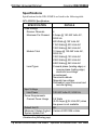
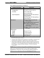
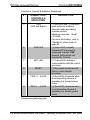
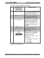
1
DIN Rail Universal Dimmer
Crestron DIN-1DIMU4
Auto Load Detection
Each channel of the DIN-1DIMU4 is capable of auto-detecting the
dimmable load type connected to it and selecting the appropriate
operating mode to control that load. Reverse phase (trailing edge) mode
supports incandescent and electronic low-voltage load types, while
forward phase (leading edge) mode handles magnetic low-voltage, neon,
and other inductive load types. A non-dim mode is also selectable for
switching of non-dimmable lighting fixtures. Any channel may be set for
any mode, allowing one dimmer module to handle any combination of
lighting types on four separately controlled circuits.
Phase-Synchronous Detection Circuitry
Crestron® proprietary zero cross filter technology provides superior
immunity to noise on the power line, reducing lamp flicker and
compensating for fluctuations in line voltage and frequency.
Short Circuit Protection
Built-in over current protection (OCP) prevents failure of the
DIN-1DIMU4 caused by excessive loading or improper wiring of the
outputs.
Master Air-Gap Relay
When all four channels are turned fully off, the internal master relay
automatically opens providing air-gap isolation to allow safe servicing
and changing of light bulbs on all four controlled circuits.
Override Input
An override input is provided to allow an external contact closure to
momentarily override the control system program and set each channel
output to its override preset level. Levels can be adjusted and saved
locally from the front panel, or remotely via software.
DIN Rail Installation
The DIN-1DIMU4 is designed to snap onto a standard DIN rail for
installation in a wall mount enclosure. Wiring connections are made
using screw terminals positioned along the bottom, clearly accessible
from the front for easy installation and servicing. All setup controls and
indicators are positioned on the center front panel. When installed in an
2 • DIN Rail Universal Dimmer: DIN-1DIMU4
Operations & Installation Guide – DOC. 6668D