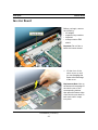
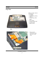
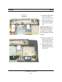
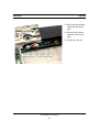
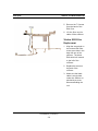
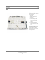
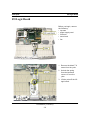
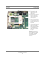
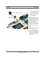
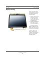
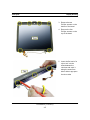
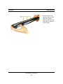
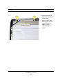
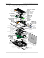
1
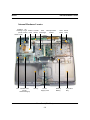
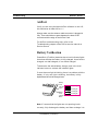
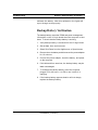
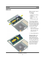
Apple Service Source
PowerBook (FireWire)
Apple Service Source
Basics
Overview
PowerBook (FireWire) is the latest addition to the PowerBook G3 Series
of computers. This version offers increased processor speeds of up to 500
megahertz (MHz), larger hard drives, DVD-ROM drives standard in all
configurations, FireWire, and wireless networking with AirPort.
To differentiate this model from previous G3 PowerBooks, look for the
FireWire ports on the back I/O panel, or the name PowerBook printed in
the middle of the bottom section of the display bezel.
PowerBook (FireWire)
1
Basics
Repair Strategy
Repair Strategy
Parts for the PowerBook (FireWire) will be available for order through
the Apple Service Price Pages and the AppleOrder system. Except for the
displays, Apple Authorized Service Providers (AASPs) in the U.S. can
repair PowerBook (FireWire) systems. In Canada, Apple Authorized
Service Providers can also repair displays.
Service PowerBook (FireWire) computers through module exchange and
parts replacement. In the U.S. only, customers can request Apple Direct
Dispatch, or they can choose carry-in service from an AASP.
Ordering
AASPs planning to support the computer systems covered in this manual
may purchase Service modules and parts to develop servicing capability.
To order parts, use the AppleOrder system and refer to the PowerBook
(FireWire) Apple Service Price Pages.
Large businesses, universities, and K-12 accounts must provide a
purchase order on all transactions, including orders placed through the
AppleOrder system.
U.S. Ordering
U.S. Apple Authorized Service Providers not enrolled in AppleOrder may
fax their orders to Service Provider Support (512-674-8125) or mail
them to
Apple Computer, Inc.
Service Provider Support
MS 212-SPS
Austin, TX 78714-9125
For U.S. inquiries, please call Service Provider Support at 800-9192775 and select option #1.
PowerBook (FireWire)
2
Basics
Warranty/AppleCare Protection Plan
Canadian Ordering
In Canada, all service parts (including the displays) are available through
AppleOrder. Refer to the Apple Service Price Pages or the Service Parts
Database on Service Source Online for part numbers and pricing.
Canadian Service Providers not enrolled in AppleOrder may fax their
orders to Service Provider Support in Canada (800-903-5284). For
Canadian inquiries, please call Service Provider Support at 800-2179517.
Warranty/AppleCare Protection Plan
PowerBook (FireWire) computers are covered under the Apple One-Year
Global Limited Warranty. The AppleCare Protection Plan is also available
for these products. AASPs are reimbursed for warranty and AppleCare
Protection Plan repairs made to these computers. For pricing
information, refer to Apple Service Price Pages or the Service Parts
Database on Service Source Online.
PowerBook (FireWire)
3
Basics
Repair Issues
Repair Issues
Do Not Remove Heat Exchanger from Microprocessor Board
Unless the microprocessor board needs to be replaced, do not separate the
heat exchanger from the microprocessor board when taking the
PowerBook (FireWire) apart. When the heat exchanger is removed, the
phase change material covering the microprocessor chip may need to be
removed and replaced. For further information, refer to the Take Apart
chapter of this manual.
Verify Model Before Ordering Parts
PowerBook (FireWire) computers look almost identical to previous
PowerBook G3 Series computers. Most parts used in the PowerBook
(FireWire) are different and are not backward- or forward-compatible.
Verify the model of computer you are repairing before ordering parts. The
configuration tool in the Service Parts Database will help you identify the
correct parts for this product.
PowerBook (FireWire)
4
Basics
FireWire
New Technologies
FireWire
FireWire is a high speed serial data bus that can move large amounts of
data between computers and peripheral devices. It features simplified
cabling, hot swapping, and transfer speeds up to 400 megabits per second
(Mbps).
FireWire allows users to connect digital consumer products such as digital
camcorders, set-top boxes, and music systems directly to the computer.
PowerBook (FireWire) is the first of Apple’s portable computers to
feature built-in FireWire ports.
For more complete technical information about FireWire, see the Tech
Info Library article 30520, “FireWire: Technology Overview.”
AirPort
AirPort is a local area network (LAN) solution for wireless networking
among multiple computers. Instead of using cables and wires, AirPort
transfers data between computers via radio waves. Through AirPort
networks, users can gain access to the Internet, send and receive email,
share files, play multi-player games, and perform other network
activities.
The AirPort product line includes the AirPort Base Station, AirPort
Software Base Station, and AirPort Card. PowerBook (FireWire) is the
first of the full-featured portable products to support it.
For more information about AirPort, see “AirPort Card” under “Boards
and Cards” later in this chapter. You can also refer to the Tech Info
Library or the AirPort service manual on Service Source.
PowerBook (FireWire)
5
Basics
AirPort
Features
PowerBook (FireWire) features include:
• PowerPC G3 microprocessor running at clock speeds of 400 or 500
MHz
• backside L2 cache of up to 1 MB of fast static RAM
• two standard SO-DIMM expansion slots for SDRAM modules and a
minimum of 64 MB of SDRAM installed, expandable to 512 MB total
• 14.1-inch TFT (thin-film transistor) display with XGA resolution
(1024 x 768 pixels)
• standard VGA video connector for external video monitor with XGA
resolution, and S-video connector that supports PAL and NTSC video
monitors
• 8 MB of video SDRAM
• Ultra ATA hard drive of up to 18 GB
• DVD-ROM with DVD-RAM readability supported
• integrated wireless communication with AirPort Card upgrade
• two hot-swappable expansion bays for two batteries or one battery and
one DVD-ROM drive
• one manual-eject CardBus slot that accepts one Type II CardBus card or
PCMCIA Card
• built-in 56 Kbps modem
• two FireWire ports with support for FireWire Disk Mode
• built-in Ethernet port with RJ-45 connector for 10Base-T and
100Base-T operation
• two USB ports for external keyboard, mouse, and other USB devices
• built-in microphone and speakers as well as a line-level stereo input
jack and a stereo headphone jack
• keyboard with embedded numeric keypad and inverted-T arrow keys.
Some function keys control the display and speakers
• trackpad with tap/double tap and drag features
• 2D and 3D graphics via ATI Rage Mobility M3 with AGP
• infrared link for up to 4 Mbit-per-second IrDA data transfer
PowerBook (FireWire)
6
Basics
Drives
Drives
Module Compatibility
Expansion modules used in the PowerBook G3 Series (Bronze Keyboard)
may be used in the PowerBook (FireWire), and vice versa. Modules from
PowerBook G3 Series computers before PowerBook G3 Series (Bronze
Keyboard) are not compatible with the PowerBook (FireWire). Any
third-party modules made for PowerBook (FireWire) also may not
function properly if used in these earlier PowerBook G3 Series
computers.
DVD-ROM Drive
All models of the PowerBook (FireWire) ship with a 4x-speed DVD-ROM
drive that is compatible with existing CD-ROM media. The DVD-ROM drive
supports the following disc formats:
• DVD-ROM
• DVD-RAM (read only)
• CD-ROM (Modes 1 and 2)
• CD-ROM XA (Mode 2, Forms 1 and 2)
• Audio CD
• Photo CD
• CD-RW (read only)
• CD-R (read only)
• CD-Extra
• CD-I (Mode 2, Forms 1 and 2)
• CD-I Ready
• CD-I Bridge
• Video CD
Hard Drive
The PowerBook (FireWire) ships with an Ultra-ATA hard drive of at least
6 GB. At introduction, hard drives of up to 18 GB are available for
configuration-to-order.
PowerBook (FireWire)
7
Basics
Memory and Power
Memory and Power
Sleep Memory Extension 1.0
Apple has identified a very rare issue that may occur when putting a
PowerBook (FireWire) to sleep. The computer may be unable to recognize
the hard drive at startup. To prevent this from happening, Apple strongly
recommends that all PowerBook (FireWire) customers running systems
prior to Mac OS 9.0.4 install the Sleep Memory Extension 1.0.
After installing the Sleep Memory Extension and restarting the computer,
the "Preserve memory contents on sleep" checkbox in the Energy Saver
control panel will be dimmed and unavailable.
Download the Sleep Memory Extension 1.0 from the Apple Software
Updates Web site at http://www.apple.com/swupdates/.
RAM Expansion
The PowerBook (FireWire) has two RAM slots on the microprocessor
board, and no RAM soldered on the I/O logic board. All units ship with a
minimum of 64 MB of factory-installed RAM. The maximum amount of
RAM supported is 512 MB. The PowerBook (FireWire) uses standard
144-pin SDRAM SO-DIMMs with a height of up to two inches.
RAM Compatibility
SDRAM SO-DIMMs used for PowerBook (FireWire) must be PC-100
compatible. Previous PowerBook G3 Series computers used PC-66 RAM
that may not be compatible with this computer.
As with the PowerBook G3 Series computers, EDO RAM should not be used.
PowerBook (FireWire)
8
Basics
Memory and Power
Battery Compatibility
The Lithium Ion (LiIon) batteries used for the PowerBook (FireWire) are
compatible with those used in the PowerBook G3 Series (Bronze
Keyboard) and vice versa. Batteries from earlier PowerBook G3 Series
computers are not compatible with PowerBook (FireWire).
Battery Level Indicators
LiIon batteries have battery level indicator lights that tell whether the
battery is fully charged, three-fourths charged, one-half charged, onefourth charged, or empty. To check the battery charge, press the status
button located next to the status lights. The battery charges whenever the
external AC adapter is connected.
If the battery lights blink, there is a problem with the battery. If only one
light blinks, the battery is fully depleted and needs to be recharged.
Battery Handling Guidelines
Warning: LiIon batteries contain hazardous chemicals and should not be
thrown out with household or office trash. Review battery handling and
disposal instructions in Safety Information in Bulletins/Safety.
The following are guidelines for properly handling batteries:
• Never get batteries wet.
• Handle the battery carefully. Do not drop, puncture, disassemble,
mutilate, or incinerate it.
• Do not leave a battery in the computer for longer than a week without
plugging in the power adapter.
• Do not short the battery contacts.
• Do not leave the battery in hot locations (such as the trunk of a car).
• Do not leave a battery in storage for longer than six months without
recharging it.
• Recharge batteries only as described in the user’s manual and only in
ventilated areas.j
PowerBook (FireWire)
9
Basics
Memory and Power
Battery Disposal and Recycling
Lithium batteries such as the backup battery in PowerBook (FireWire)
require disposal when dead, but you cannot throw them away. In Addition to
being potentially explosive, lithium is water reactive, requiring these
batteries to be disposed of as hazardous waste.
After removing a dead backup battery, clip off the lead wires and place the
battery into the zip-lock wrapper that the replacement battery came in.
Call your local or regional solid waste agency or recycling organizations to
find out about battery disposal options in your area.
PowerBook (FireWire)
10
Basics
Sound and Video
Sound and Video
Sound
The PowerBook (FireWire) supports 44.1 kHz 16-bit stereo sound
output and input, available simultaneously. Sound output is through either
the built-in speakers or the external sound output jack.
Sound input can come from:
• built-in microphone
• external stereo sound input jack
• modem slot
• CardBus socket
• expansion bay device
Video
The PowerBook (FireWire) 14.1 inch thin-film transistor (TFT) display
contains 1024 x 768 pixels and shows up to millions of colors. Both the
internal display and an external monitor are supported by an ATI Rage
Mobility M3 IC.
Features of the Rage Mobility M3 include:
• 8 MB of embedded SDRAM
• 3D acceleration
• video acceleration
• MPEG decoding support
• dual-display mode support
• composite video output for a TV monitor
PowerBook (FireWire)
11
Basics
Input and Output
Input and Output
Keyboard and Trackpad
The keyboard and trackpad are the same design as those used in the earlier
PowerBook G3 Series of computers. The PowerBook (FireWire) keyboard
includes a built-in numeric keypad and controls to adjust display
brightness, speaker volume, and external audio port volume.
Several of the keys on the keyboard have more than one mode of operation.
These changes are controlled by the Fn key, the Num Lock key, and the
Function Keys checkbox in the Keyboard control panel.
FireWire Ports and Target Disk Mode
The PowerBook (FireWire) has two external FireWire ports. The ports:
• support serial I/O at up to 400 Mbps
• provide up to 6 watts of power when the computer is turned on
• accept external power input from the bus
• support starting up the system from a mass storage device
• support target disk mode
Target Disk mode is similar to SCSI Disk mode, except it uses a FireWire
connection. When the PowerBook is in Target Disk mode, the PowerBook
operates as a mass storage device. The two primary uses of this feature
are:
• high-speed data transfer between computers or devices
• diagnosis and repair of a corrupted internal hard drive
To put the PowerBook in Target Disk mode, press the T key while starting
up. To take the PowerBook out of Target Disk mode, press the power
button.
USB Ports
The PowerBook (FireWire) has two Universal Serial Bus (USB) ports
that can be used to connect I/O devices such as a USB mouse, printers,
PowerBook (FireWire)
12
Basics
Input and Output
scanners, and low-speed storage devices. The ports use USB Type A
connectors, which have four pins.
Ethernet Port
The PowerBook (FireWire) has a built-in 10/100 Mbps Ethernet port.
When connected to either a 10Base-T or a 100Base-T hub, the port will
recognize which type of hub is connected.
The connector for the Ethernet port is a short, shielded RJ-45 connector
on the back of the computer.
Infrared
The PowerBook (FireWire) has a direct infrared (IR) communication
link connected internally to a serial port on the KeyLargo IC. The IR link in
the PowerBook (FireWire) supports IrDA at up to 4.0 Mbps.
PowerBook (FireWire)
13
Basics
Boards and Cards
Boards and Cards
General
The architecture of the PowerBook (FireWire) is designed around two
main circuit boards: the microprocessor board and the I/O logic board.
Besides the two main boards, the PowerBook (FireWire) can contain up to
seven cards: power supply card, sound card, RAM card (factory installed),
RAM card (user installed), AirPort Card, modem, and modem EMI filter.
AirPort Card
The AirPort Card transmits and receives data at up to 11 Mbps. Connecting
to the Internet or a wired local area network (LAN) requires a base station
as the connection to the Internet or a bridge between the wireless signals
and a wired LAN. Software included with the AirPort Card enables a
Macintosh computer that has an AirPort Card installed to act as a base
station.
In PowerBook (FireWire), the AirPort Card is installed under the
keyboard and above the PCMCIA Card slot.
PCMCIA (PC) Cards
The PCMCIA Card slot accepts one Type II card. The slot supports both 16bit PC Cards and 32-bit CardBus cards. Cards can be removed and replaced
while the computer is operating. The slot supports Zoomed Video on the
card connector.
To eject a PC card, first drag the PC Card icon (if present) to the trash.
Then push once on the eject button to release the button, and a second time
to eject the card.
The following are guidelines for properly handling PC Cards:
• Use only cards that are compatible with the PC Card unit. Refer to the
compatibility information that came with the PC Card. If you cannot
PowerBook (FireWire)
14
Basics
Boards and Cards
•
•
•
•
•
find the compatibility information, contact the card vendor.
Do not insert anything other than a PC Card into the card slots.
The computer must be on or off to eject a PC Card. Do not eject a PC
Card when the computer is in sleep mode.
Before you eject a card, make sure nothing is blocking the card’s slot.
To use the card again immediately, pull it out about an inch more and
then push it back in. If you don’t follow this procedure and try to push
the card back in to use it again, the card will not engage properly.
Do not pull on a PC Card before it has been ejected out of the slot.
Forcing a PC Card out of the slot may damage the computer or the card.
If the card is partially ejected, use pliers to carefully pull the card out
the rest of the way.
PowerBook (FireWire)
15
Basics
Left Side View
Views
Left Side View
PowerBook (FireWire)
16
Basics
Front View
Front View
PowerBook (FireWire)
17
Basics
Right Side View
Right Side View
PowerBook (FireWire)
18
Basics
Rear View
Rear View
PowerBook (FireWire)
19
Basics
Internal Hardware Locator
Internal Hardware Locator
PCMCIA I/O
Cardcage Logic AirPort
(Under Board Card
AirPort Card)
Fan
Modem Card
(Under
Heat Exchanger)
Heat
Inverter
Microprocessor
Board Exchanger
Board
Battery
Power
Supply Card
PowerBook (FireWire)
20
Hard Sound
Drive Card
Backup
Battery
Expansion
Bay
Basics
I/O Logic Board Drawing
I/O Logic Board Drawing
PCMCIA CardCage
Connector
RJ-11 Cable/
Phone Jack
Connector
Display
Cable Connector
Sound Card
Connector
Hard Drive
Connector
Microprocessor
Board
Connector
Fan
Modem
Connector Connector
Keyboard
Connector
Trackpad
Connector
Power
Supply
Card
Connector
PowerBook (FireWire)
21
Backup
Battery
Connector
Expansion
Bay
Connector
Basics
Microprocessor Board Drawing
Microprocessor Board Drawing
Microprocessor
Board
RAM
Card Slot
Pull
Tab
Heat
Exchanger
Mounting
Bracket
I/O Logic Board Connector
(Underside of Board)
(Underside of Board)
Factory-Installed RAM
Card Slot
PowerBook (FireWire)
22
Apple Service Source
Specifications
Introduction
Specifications information for this product can be found in the
SpecDatabase, which you can access at Service Source Online
(http://service.info.apple.com) or on Service Source CD.
Spec Database at Service Source
Online
From the Service Source Online home page, click Troubleshoot
and Repair to access the main repair procedures page. Then
click either Apple Spec in the navigation table in the upper
right corner of the page, or click Apple Spec Database from the
list of reference tools below.
Spec Database on Service Source CD
Open the CD and double-click the Apple Spec Database alias
located at the top level of the CD.
PowerBook (FireWire)
1
General - 1
Apple Service Source
Troubleshooting
General
In each service manual on Service Source, you will find
Flowcharts and/or Symptom Charts designed to help you
diagnose and repair Apple computers.
If you have narrowed the problem down to a particular
symptom, start with the Symptom Charts. Because cures are
listed in the order of most likely solution, try the first cure
first. Verify whether or not the product continues to exhibit
the symptom. If the symptom persists, try the next cure.
If you are not sure what the problem is, or if the Symptom
Charts do not resolve the problem, refer to the Flowcharts.
Diagnostic tools are also available to help you isolate a
hardware problem. Refer to the Diagnostics page of Service
Source, which you can access on Service Source CD or at
Service Source Online (http://service.info.apple.com).
If you require additional assistance, contact Apple Technical
Support.
PowerBook (FireWire)
General / Power-On Self Test - 2
Troubleshooting
Power-On Self Test
There is a power-on self test that resides in the ROM of the
PowerBook (FireWire). This test automatically runs
whenever the computer is powered on after being fully shut
down (the power-on self test does not run if the computer is
only restarted).
If a problem is detected during the test, you will not hear a
normal startup chime. Instead, the system will beep as
explained in the Power-On Self Test Beep Definitions chart.
Power-On Self Test Beep Definitions
Beeps
Definition
1 beep
No RAM is installed or detected.
2 beeps
EDO memory is installed. The PowerBook (FireWire)
ships with SDRAM SO-DIMMs and does not accept EDO
memory.
3 beeps
No RAM banks passed memory testing.
4 or 5 beeps
Bad checksum for the remainder of the boot ROM. The
ROM (which is located on the microprocessor module)
is bad.
PowerBook (FireWire)
General / AirPort - 3
Troubleshooting
AirPort
Verify you are using the latest AirPort software. In the U.S.,
this should be at least AirPort 1.1.
Always make sure the antenna cable connector is plugged in
fully. There should be no space between the base of the
connector and the edge of the AirPort Card.
For AirPort troubleshooting help, refer to the
Troubleshooting chapter of the AirPort service manual on
Service Source.
Battery Verification
PowerBook (FireWire) batteries have level-indicator lights
that show whether the battery is fully charged, three-fourths
charged, one-half charged, or one-fourth charged.
To determine the actual battery charge, push in the level
indicator button to activate the indicator lights.
If more than one light is blinking, there is a problem with the
battery. If only one light is blinking, the battery is fully
depleted and should be charged soon.
Battery
Level
Indicator
Lights
Battery
Level
Indicator
Button
Fully charged
3/4 charged
1/2 charged
1/4 charged
Note: If it seems that the lights are not reporting levels
correctly, fully discharge the battery and then recharge it to
PowerBook (FireWire)
Troubleshooting
General / Backup Battery Verification - 4
calibrate the battery. After this calibration, the lights will
report charge levels properly.
Backup Battery Verification
The backup battery saves the PRAM and power management
information on the I/O logic board when the computer is shut
down. To check that the backup battery is working:
1. Verify backup battery is connected to the I/O logic board.
2. Set the date, time, and time zone.
3. Select Shut Down from the Apple menu or Special menu.
4. Remove the main battery and disconnect the power adapter
for 10 minutes.
5. Connect the power adapter, insert the battery, and power
on the computer.
6. If the date and time were lost, the backup battery may be
dead or discharged.
7. To recharge the backup battery, leave the computer
plugged in for 48 hours. It is OK to use it while it is
charging.
8. If the backup battery appears dead or will not charge,
replace the backup battery.
PowerBook (FireWire)
General / Reset PRAM - 5
Troubleshooting
Reset PRAM
Important: Resetting PRAM erases the contents of the RAM
disk, if there is one. Resetting PRAM also restores the default
settings in most control panels. After you reset PRAM, be
sure to check any custom settings for the desktop pattern,
memory, network, AppleTalk, trackpad, power conservation,
and so forth.
To reset PRAM:
1. Power on the computer by pressing the Power key.
2. Immediately press Option-Command-P-R.
3. Press the four keys until you have heard the startup
chime at least one additional time after the initial startup
chime.
Reset the Power Manager
PowerBook (FireWire) computers have a reset button located
on the back of the computer behind the I/O door. Press the
button once to reset the power manager.
PowerBook (FireWire)
General / Block Diagram - 6
Troubleshooting
Block Diagram
Backside
L2 cache
SO-DIMM
slots
100 MHz
Max bus
100 MHz
memory bus
66 MHz RAGE 128 M3
AGP bus
graphics IC
Uni-N
memory
controller
and PCI
bus bridge
CardBus slot
connector
PCI1211
CardBus
bridge
32-bit
33MHz
PCI bus
S-video connector
VGA monitor
connector
Ethernet
PHY
Ethernet port
FireWire
PHY
FireWire port
FireWire port
Boot
ROM
Expansion
bay connector
ATA bus
Connector to
internal IDE
disk drive
Ultra-ATA
bus
Screamer
sound IC
Connector to
internal antenna
RF
and
IF
Connector to
Internal display
PowerPC G3
microprocessor
DSP and
MAC
KeyLargo
I/O device
and disk
controller
Sound in jack
Sound out jack
Internal
speaker
connector
IrDA link
USB port
USB port
Wireless LAN module
Controller
and DAA
PMU99
power
controller
Modem module
PowerBook (FireWire)
Telephone
connector
Symptom Charts / Start Up - 7
Troubleshooting
Symptom Charts
Start Up
RAM failure occurs
(beeps are heard at
start up)
Note: There is no RAM on the microprocessor board itself, so the
computer will beep if no memory is installed in at least one of the
slots.
1.
Remove top RAM SO-DIMM (if present) and restart computer.
If startup sequence is normal, replace RAM SO-DIMM and
retest. Note: Verify RAM is PC-100 compatible.
2.
Replace bottom RAM SO-DIMM and retest.
3.
Replace microprocessor board.
4.
Replace I/O logic board.
Power
Computer won’t
power up
1.
Restart computer by pressing the reset button on the back of
the unit. Wait five seconds and press the Power key.
2.
Try known-good power adapter.
3.
Try known-good, firmly seated, charged battery. Repeat.
4.
Connect power adapter and restart computer in 3-4 minutes.
5.
Disconnect internal keyboard completely and try powering up
unit. If unit powers up, replace keyboard.
6.
Verify microprocessor card is firmly seated.
7.
Replace sound card.
8.
Replace power supply card.
9.
Replace microprocessor board.
10. Replace I/O logic board.
PowerBook (FireWire)
Symptom Charts / Power - 8
Troubleshooting
Screen is blank;
backlight isn’t on;
computer doesn’t
respond
1.
Restart the computer by pressing the reset button on the back
of the unit. Wait five seconds and press the Power key.
2.
Restart computer.
3.
Disconnect power adapter and remove battery, then wait 3-4
minutes. Reconnect computer to power source and restart.
4.
Check power adapter cable.
5.
Try known-good, charged battery.
6.
Try known-good power adapter.
7.
Remove all power (power adapter and batteries) and
disconnect backup battery for ten minutes.
8.
Check all I/O logic board cables and connections.
9.
Replace sound card.
10. Replace microprocessor board.
11. Replace power supply card.
12. Replace I/O logic board.
Power adapter is
plugged in, but
Control Strip doesn’t
indicate adapter is
connected
After you remove
battery and power
adapter, some Control
Panel settings are
different
1.
Verify power adapter is connected correctly and the power
cord is plugged solidly in the adapter.
2.
Verify there is power at the outlet.
3.
Try known-good power adapter.
4.
Try known-good power cord.
5.
Reset power manager (press reset button behind the I/O door.
6.
Replace sound card.
7.
Replace power supply card.
8.
Replace I/O logic board.
1.
Connect power adapter to unit for 24 hours to see if backup
battery is just depleted. (It takes approximately 48 hours to
fully charge the backup battery.)
2.
Check backup battery cable and connections.
3.
Replace backup battery.
4.
Replace I/O logic board.
PowerBook (FireWire)
Symptom Charts / Power - 9
Troubleshooting
Computer functions
when plugged into
wall outlet but not on
battery power
Battery won’t charge
Battery will not
charge unless unit is
in sleep mode or shut
down
1.
Verify battery is charged by pressing the level indicator
button on the battery. If the battery is charged, one or more
status lights on the battery will glow.
2.
Reseat battery to make sure battery is mating with contacts on
I/O logic board.
3.
Try battery in opposite expansion bay.
4.
Try known-good, firmly seated, charged battery. Try the same
battery in opposite expansion bay.
5.
Turn off the computer. Press the reset button on the back of
the unit, wait five seconds, then press the Power key.
6.
Try known-good power adapter.
7.
Replace power supply card.
8.
Replace I/O logic board.
1.
Verify battery is charged by pressing the level indicator
button on the battery. If the battery is charged, one or more
status lights on the battery will glow.
2.
Turn off the computer. Press the reset button on the back of
the unit, wait five seconds, and press the Power key.
3.
Try battery in opposite expansion bay.
4.
Try known-good, firmly seated, charged battery. Try the same
battery in opposite expansion bay.
5.
Replace power supply card.
6.
Replace I/O logic board.
Verify the appropriate power adapter is being used.
PowerBook (FireWire)
Symptom Charts / Video - 1 0
Troubleshooting
Video
Pixel(s) always on or
off
1.
A certain number of pixel anomalies are inherent in display
technology and vary by many factors, including type of
technology. If you suspect that the display contains an
abnormal number of anomalies, contact Apple Technical
Support.
Warning: Do not use a metal screwdriver to reseat the display cable
or shorting could result. Use a plastic or nylon tool.
Partial or full row of
pixels is always on or
always off
Display is very light
or totally white
An external monitor
connected to the
computer shows no
video
1.
Check display cable connection.
2.
In the U.S., contact Apple Technical Support.
3.
Replace display cable (international only).
4.
Replace display (international only).
5.
Replace I/O logic board.
1.
Verify display cable and inverter board cable connections to
the I/O logic board.
2.
Replace inverter board.
3.
In the U.S., contact Apple Technical Support.
4.
Replace display cable (international only).
5.
Replace display (international only).
1.
Verify external monitor has power.
2.
Try different resolutions in the Monitors control panel.
3.
Try another monitor cable and verify the video adapter has
part number 590-1123 on the adapter.
4.
Try another monitor.
5.
Restart unit and reset PRAM.
6.
Replace I/O logic board.
PowerBook (FireWire)
Symptom Charts / Video - 1 1
Troubleshooting
No display, but
computer appears to
operate correctly
1.
Connect power adapter.
2.
Adjust screen brightness using keyboard controls.
3.
Verify display cable, inverter board, and I/O logic board
connections.
4.
Connect external, known-good monitor.
5.
Verify inverter cable is properly connected.
6.
Replace inverter cable.
7.
Replace inverter board.
8.
In the U.S., contact Apple Technical Support.
9.
Replace display cable (international only).
10. Replace display (international only).
11. Replace I/O logic board.
An external monitor
connected to the
computer shows
either horizontal or
vertical rolling, or
horizontal or vertical
distortion
1.
Try different resolutions in the Monitors control panel.
2.
Verify monitor using another computer.
3.
Try another video adapter and verify the video adapter has
part number 590-1123 on it.
4.
Replace I/O logic board.
Backlight doesn’t
operate; screen is
very dim
1.
Adjust screen brightness setting.
2.
Verify backlight cable connection is secure.
3.
Check display cable and inverter board connections to the I/O
logic board.
4.
Verify inverter cable is properly connected and that cable is
good.
5.
Verify cables are not pinched or severed.
6.
Replace inverter board.
7.
In the U.S., contact Apple Technical Support.
8.
Replace display (international only).
9.
Replace I/O logic board.
PowerBook (FireWire)
Symptom Charts / Sound - 1 2
Troubleshooting
Sound
No sound from
speaker(s)
Startup sound is
heard, then no sound
from speaker(s)
1.
Verify mute mode is not enabled (F6 on the keyboard).
2.
Check the volume setting in the Sound control panel.
3.
Verify no external speakers or headphones are plugged in.
4.
Reset PRAM.
5.
Make sure speaker cable is plugged into sound card.
6.
Replace sound card.
7.
Replace speakers (part of the top case).
8.
Replace I/O logic board.
1.
Remove sound preferences from System Folder, reset PRAM,
then restart.
2.
Perform clean installation of system software.
Hard Drive
Internal hard drive
does not spin
Expansion bay module
will not insert
properly in the
expansion bay
1.
Make sure power adapter is connected.
2.
Disconnect external devices.
3.
Check hard drive connection.
4.
Replace hard drive cable. Note: Pull up evenly on the cable to
avoid bending pins.
5.
Replace hard drive.
6.
Replace I/O logic board.
1.
Check for obstructions in the expansion bay.
2.
Check that the far right keyboard tab is inserted properly and
not extending into the expansion bay.
3.
Try another module.
4.
Replace I/O logic board.
PowerBook (FireWire)
Troubleshooting
Symptom Charts / PC Card Module (PCMCIA) -
PC Card Module (PCMCIA)
PC Card won’t eject
PC Card is inserted
but doesn’t appear on
desktop
PC Card can’t be
inserted
1.
Make sure computer is not in sleep mode.
2.
Make sure PC Card slot is not blocked.
3.
Drag PC Card to trash.
4.
Try PC Card eject button. (Press the PC Card eject button
once to release the button, then again to eject the card.)
5.
Remove keyboard and AirPort Card (if installed), then gently push
the card out with your finger.
6.
Verify PC Card is not warped or damaged in any way; if so,
replace with new card.
7.
Replace PCMCIA cardcage.
Note: Modem and communication cards may not appear on desktop.
1.
Verify correct software for the PC Card is installed.
2.
Manually eject the PC Card and reinsert it.
3.
Try another PC Card.
4.
Replace PCMCIA cardcage.
5.
Replace I/O logic board.
1.
Make sure PC Card is right side up (cards are keyed and
cannot be inserted upside down).
2.
Check for obstructions in the PC Card slot.
3.
Push PC Card in from center of the exposed edge.
4.
Try a different PC Card.
5.
Replace PCMCIA cardcage.
PowerBook (FireWire)
Symptom Charts / DVD-ROM Drive - 1 4
Troubleshooting
DVD-ROM Drive
Drive does not accept
disc
Volume control does
not operate correctly
Computer cannot
mount disc
1.
Verify disc is properly seated in the carrier.
2.
Reinsert drive in expansion bay.
3.
Replace drive.
4.
Replace I/O logic board.
1.
Check Sound control panel setting.
2.
Verify mute mode is not enabled.
3.
Verify the setting of volume control button.
4.
Reinsert drive.
1.
Reinsert drive.
2.
Replace disc (if dirty or damaged).
3.
Verify Apple CD/DVD ROM extension is installed.
4.
Replace drive.
5.
Replace I/O logic board.
DVD-Video
Movie plays, but
special features (such
as director’s notes
and other languages)
are unavailable
1.
Not all DVD titles offer special features. Check the liner notes
included with the disc for a list of features.
2.
If both the picture and sound are OK, then DVD drive is
functional. This means either the software or the movie title
(DVD video disc) is the source of the symptom. Try playing
another title to determine if the disc is the cause. If the
software is the cause, reinstall software.
PowerBook (FireWire)
Troubleshooting
DVD video movie will
not play
Poor performance of
DVD video disc (poor
sound or picture)
Symptom Charts / Infrared Communication -
1.
Clean the disc with an appropriate cleaner.
2.
Try another DVD video disc.
3.
Ensure DVD video disc appears on desktop.
4.
Check that Parental Controls setting is set to On. Select an
MPAA rating at the same level or higher than the title being
viewed.
5.
Check region code for DVD video title. (Warning message
appears.)
6.
Reinstall software.
1.
Check the DVD video disc for scratches.
2.
Disable background applications.
3.
Turn off AppleTalk and TCP/IP.
4.
Set display to millions of colors.
5.
Set Disk Cache to default setting in Memory control panel.
6.
Use Extensions Manager to disable extensions except for the
standard Apple extensions and DVD extensions. Restart the
computer.
7.
For an audio problem, try playing an audio CD. If problem
persists, refer to the Sound symptom chart in this chapter.
Infrared Communication
Infrared
communication is not
working
1.
Clean infrared window with soft lint-free cloth.
2.
Make sure units are spaced 3-6 feet apart and at less than a
20 degree angle.
3.
Verify infrared signal is being received by host computer.
4.
Replace I/O logic board.
PowerBook (FireWire)
Symptom Charts / Modem - 1 6
Troubleshooting
Modem
No dial tone
No internal modem
selection available
Modem reports an
error when dialing
out
Modem is having
trouble connecting to
Online site
1.
Verify known-good analog (not digital) telephone line.
2.
Verify cable is not plugged into Ethernet port.
3.
If using Apple Remote Access 3.0, select Ignore Dial Tone in
the Modem control panel. If the modem connects with this
setting selected, try another phone line. If using a terminal or
communications program, enter “atx1” to disable tone
detection. To reset the modem back to the factory settings,
enter “atz.”
4.
Replace cable/phone jack.
5.
Replace modem EMI filter card.
6.
Replace modem.
1.
Remove keyboard and verify modem is properly installed and
modem EMI filter card is plugged in.
2.
Verify correct modem software is installed and selected.
3.
Replace modem.
1.
Use the Modem Country Selector utility to make sure the
modem is set to the correct country.
2.
Make sure the correct driver is installed and the correct CCL
is selected and that they are not corrupted. If necessary,
reinstall the driver and/or CCL.
3.
Try another cable and phone jack.
4.
If problem persists, reinstall system and modem software.
1.
Use the Modem Country Selector utility to make sure the
modem is set to the correct country.
2.
The phone line may have too much noise. If the user has a
second line, try that one. The user should contact their local
phone company and request their line be checked.
3.
Check to make sure the TCP/IP control panel is correctly
configured for the user's Internet Service Provider. If the
PowerBook (FireWire)
Symptom Charts / Modem - 1 7
Troubleshooting
TCP/IP control panel is not configured correctly, it may
connect but won’t be able to access any sites.
4.
Sometimes online services use different servers for dial-up/
authentication and for services. If one server is down, users
may be able to login but not access any services. Contact the
online service for help.
The dialup software
will not initiate a
connection
1.
Use the Modem Country Selector utility to make sure the
modem is set to the correct country.
2.
Make sure dialup software is fully installed and all required
extensions are enabled. If necessary, reinstall the dialup
software and provide the necessary information for setup.
Modem is dropping its
connection
1.
Use the Modem Country Selector utility to make sure the
modem is set to the correct country.
2.
Try another cable and phone jack.
3.
The phone line may be too noisy to handle the higher modem
speeds. Try connecting at a slower speed or use a generic CCL
file. (If you are familiar with the CCL script language, you
can edit the modem script to force a connection at a lower
speed.) If the problem continues, contact the phone company
to report the bad phone line.
4.
Verify that the user has call waiting on that phone line. With
call waiting active, an incoming call can interrupt the
connection. Disable call waiting using AT commands placed in
the init string of the dialup application. Usually the string is
*70.
5.
There may be a problem with the server to which you are
connecting. Servers sometimes develop problems that
disconnect users without explanation. Try calling back later
or use an alternate number if one is available.
6.
Check with the Internet Service Provider.
7.
Reseat the modem. If the problem persists, replace the
modem.
PowerBook (FireWire)
Symptom Charts / USB and FireWire - 1 7
Troubleshooting
USB and FireWire
1.
Disconnect all external devices and start up computer. Then
plug in devices.
2.
Eliminate chain by plugging in only one device.
3.
Try another port.
4.
Start up system with extensions off.
5.
If device is self-powered, power on external device before
starting computer.
6.
Check cable connections.
7.
Try known-good cable.
8.
Try known-good external device.
9.
Replace I/O logic board.
Computer starts up to
a floating FireWire
icon (similar to SCSI
Disk Mode)
1.
Reset computer.
2.
Replace keyboard.
3.
Replace I/O logic board.
In target disk mode,
computer does not
display FireWire icon
until host is started
up, or computer
crashes when host is
shut down
1.
Verify FireWire cable is good and check the connection.
2.
Make sure host computer is running FireWire 2.3 or later. Use Apple
System Profiler to verify.
3.
Make sure no other FireWire devices are connected.
4.
Verify computer was started up with the T key pressed.
5.
Check the keyboard connection.
6.
Replace keyboard.
7.
Replace I/O logic board.
After you connect
external USB or
FireWire device,
computer does not
start up
PowerBook (FireWire)
Symptom Charts / USB and FireWire - 1 8
Troubleshooting
USB or FireWire
device, such as digital
camera, not
recognized by
computer
I/O devices are
unrecognized, or
garbage is
transmitted or
received
Cursor does not move
when using trackpad
Note: If you are trying to use a serial device with a USB/Serial
adapter, check with the manufacturer for compatibility.
1.
Verify current driver for the device is installed.
2.
Turn on camera before launching desktop video (DV)
application.
3.
Try different USB or FireWire device on same port.
4.
Eliminate chain by plugging in only one device.
5.
Try the other USB or FireWire port.
6.
Replace I/O logic board.
1.
Check cables.
2.
Check with vendor for current drivers.
3.
Try other USB or FireWire port.
4.
Reset PRAM.
5.
Test device with known-good computer.
6.
Replace I/O logic board.
1.
Shut down computer, unplug power adapter, and remove
battery. Let computer sit for one minute before restarting.
2.
Reset power manager (press the reset button behind the I/O
door).
3.
Check trackpad connections.
4.
Connect USB mouse and try to move cursor. If trackpad does
not move cursor but external USB mouse does, replace
trackpad (included in top case).
5.
Replace I/O logic board.
PowerBook (FireWire)
Symptom Charts / USB and FireWire - 1 9
Troubleshooting
Cursor moves on
screen with external
mouse connected, but
clicking or doubleclicking the mouse
has no effect
Cursor moves, but
clicking trackpad
button has no effect
Cursor does not move
on the screen with an
external mouse, but
USB external
keyboard works
1.
If the mouse is connected to an external keyboard, connect the
mouse to one of the USB ports on the computer.
2.
Try the other USB port.
3.
Try another mouse.
4.
Reset PRAM.
5.
Start up from the CD that came with the computer. If the
mouse works, reinstall the system software.
6.
Replace I/O logic board.
1.
Reset power manager (press the reset button behind the I/O
door).
2.
Remove top case and manually press trackpad button on power
supply with a nylon tool or other non-metal object. If button
activates cursor, check top case seating.
3.
Replace power supply card.
4.
Replace trackpad button actuator (included in the top case).
1.
Verify the mouse is connected securely to the USB keyboard or
port.
2.
Check inside mouse for buildup of dirt or other contaminants.
Clean mouse if necessary.
3.
If mouse is connected to the keyboard, connect it to a USB port.
4.
Try the other USB port.
5.
Try another mouse.
6.
Replace I/O logic board.
PowerBook (FireWire)
Symptom Charts / USB and FireWire - 2 0
Troubleshooting
Cursor intermittently
does not move or
moves erratically
No response to any
key on keyboard
Known-good Ethernet
network printer does
not print
Note: User must touch trackpad with the surface of only one finger
at a time and point directly down on the trackpad surface.
1.
Clean trackpad surface with computer off, using a non-staticinducing material.
2.
Reset power manager (press the reset button behind the I/O
door).
3.
Turn off clicking in Trackpad control panel.
4.
Try unit on battery power. If problem goes away, replace
power adapter.
5.
Check trackpad connections.
6.
Replace trackpad (included in top case).
7.
Replace I/O logic board.
1.
Reset the power manager (press the reset button behind the I/
O door).
2.
Check keyboard connection by disconnecting and reconnecting
keyboard cable.
3.
Replace keyboard.
4.
Replace I/O logic board.
1.
Verify Chooser and networking control panel (AppleTalk and
TCP/IP) settings are correct.
2.
Reinstall printer drivers.
3.
Check printer cables.
4.
Attach computer directly to printer using Ethernet crossover
cable, and retest.
5.
Reset PRAM.
6.
Replace I/O logic board.
PowerBook (FireWire)
Symptom Charts / USB and FireWire - 2 1
Troubleshooting
Known-good USB
printer does not print
1.
Verify computer has correct driver installed. Check vendor’s
Web site to download current driver.
2.
Reset PRAM.
3.
Verify printer is selected in the Chooser.
4.
Run Apple System Profiler to see if it recognizes the USB
printer is connected. If it does, it is a software issue.
5.
Try the other port. Make sure the printer is connected
directly to the computer.
6.
Check cables.
7.
Replace I/O logic board.
Power-related error
message appears
1.
Plug the device into an electrical outlet if it has a power cord.
2.
Unplug the device and plug it into another USB port on the
computer or another device plugged into a power outlet such
as a USB hub.
After sleep, a USB
device is sometimes
not recognized
1.
Restart the computer.
2.
Contact device manufacturer for latest driver update.
PowerBook (FireWire)
Symptom Charts / Miscellaneous - 2 2
Troubleshooting
Miscellaneous
Sleep light doesn’t
turn on
Screen goes blank and
computer shuts down
every few minutes
1.
Verify computer is in sleep mode and not off.
2.
Reset power manager (press the reset button behind the I/O
door.
3.
Replace inverter board.
1.
Computer is going into system sleep to conserve battery
power. Adjust sleep delays in Energy Saver control panel or
connect power adapter.
2.
Verify the appropriate power adapter is being used.
3.
Try a known-good power adapter.
Application seems to
run slower after a few
seconds
Computer is in processor cycling mode. If this interferes with
operation of application, turn off Allow Processor Cycling in the
Energy Saver control panel. Note: This feature conserves energy
when running off battery power.
Hard drive is slow to
respond, or screen
goes blank too often
Adjust sleep delays in Energy Saver control panel or connect power
adapter.
Fax software is not
working
The PowerBook (FireWire) comes with FaxSTF software installed.
Apple does not provide support for this software. Contact Smith
Micro at 949-632-5810 or send email to
[email protected].
PowerBook (FireWire)
Symptom Charts / Miscellaneous - 2 3
Troubleshooting
Intermittent
operating problems
such as not starting
up or initialization
errors
1.
Remove the microprocessor EMI shield and check that the two
screws over the microprocessor unit and the screw on the left
side of the heat exchanger are installed.
2.
Verify microprocessor board is properly installed.
3.
Press on microprocessor board a second time to make sure the
board is fully seated.
Important: The microprocessor board can be partially inserted and
the computer will still function. However, over time, heat will
cause a partially seated microprocessor board to lose contact and
cause intermittent system problems. The connection of these
boards is checked and double-checked at the factory.
4.
Remove the heat exchanger and examine the black thermal
transfer material over the microprocessor chip. Follow the
procedures in the Take Apart chapter of this manual to replace
the heat exchanger.
PowerBook (FireWire)
Symptom Charts / Miscellaneous - 2 4
Troubleshooting
Startup Problems Flowchart
START
Reset the
power manager.
Press power button to
begin startup sequence.
Do you
hear the
startup
tones?
No
Does any
video
appear?
No
1. Check the display cables.
2. Replace the power supply
card.
3. Replace the sound card.
Yes
Yes
1. Check the volume.
2. Check the keyboard and
display cables.
3. Replace the sound card.
4. Replace the speaker.
5. Replace the I/O logic board.
Are the
startup tones
normal?
No
See Startup in the
Symptom Charts.
Yes
Does a
gray screen
appear with
pointer?
Yes
No
1. Check display/inverter cable
connections.
2. Replace the display and
backlight cables.
3. Replace the inverter.
4. Replace the display.
5. Replace the I/O logic board.
1
PowerBook (FireWire)
Troubleshooting
Symptom Charts / Startup Problems Flowchart
Startup Problems Flowchart (continued)
Go to
Start
1
Does
the
PowerBook continue
to start up to the
desktop?
Does
the flashing
question mark
appear?
No
Yes
Yes
No
1. Start up with extensions off.
2. Start up with the CD that
comes with the computer
(press the C key).
3. Replace the hard drive.
4. Replace the I/O logic
board.
1.
2.
3.
4.
Reset PRAM.
Start up from the CD that comes with the computer.
If hard drive appears, reinstall system software.
If hard drive doesn't appear,see if Drive Setup
can reformat it.
5. Replace the hard drive cable.
6. Replace the hard drive.
7. Replace the I/O logic board.
Do the
trackpad and
keyboard
function?
No
Yes
1. Reset the power manager.
2. Check the trackpad and
keyboard cables.
3. Replace the trackpad and
keyboard cables.
4. Replace the trackpad.
5. Replace the keyboard.
6. Replace the I/O logic board.
Insert a known-good
CD-ROM or DVD disc
and see if it mounts.
Does the
disc
mount?
No
1.
2.
3.
4.
Check for proper software drivers.
Reseat the module.
Replace the module.
Replace the I/O logic board
Yes
END
PowerBook (FireWire)
Apple Service Source
Take Apart
General
Tools
Use the following tools for procedures in this chapter:
• 5 mm nut driver
• #8 Torx screwdriver (T-8)
• #1 Phillips screwdriver
• flat-head jeweler’s screwdriver (for keyboard lock)
• flat-blade nylon or plastic tool (spudger)
• dental pick or hook tool (to open flex connectors)
• razor blade or X-Acto knife (to remove screw covers)
PowerBook (FireWire)
1
Take Apart
Cables
Cables
Follow these guidelines when working with cables:
• Ensure all cables are routed exactly when reassembling.
Use all grooves and/or protrusions to align cabling. If the
cable is improperly routed, you may not be able to
reassemble the computer, or once reassembled, the
computer may fail to function.
• Check that all cables are properly aligned in the
connectors and that the connections are tight.
• Handle flex cables carefully. Using excessive force to
disconnect a cable can tear the cable or damage it so it will
not work properly.
• Use a nylon tool or dental pick to help loosen cable
connections.
PowerBook (FireWire)
2
Take Apart
Expansion Bay Modules
Procedures
Expansion Bay Modules
Before you begin, unplug
the AC adapter.
Important: You must
remove all modules
(batteries and drives) in
the expansion bays before
performing any Take Apart
procedure.
PowerBook (FireWire)
3
Take Apart
Expansion Bay Modules
1. Open the display to a
90-degree angle to
prevent the computer
from tipping over
when the expansion
bay modules are
removed.
Note: If you open the
display all the way,
support the underside of
the screen with a book or
other flat object.
2. Pull the expansion bay
eject arm toward you
to eject the module.
3. Slide the module out of
the expansion bay.
PowerBook (FireWire)
4
Take Apart
Keyboard
Keyboard
Before you begin, remove
the following:
• AC adapter
• expansion bay modules
Note: You do not need to
disconnect and remove the
keyboard completely to
gain access to the hard
drive, SDRAM DIMMs,
backup battery, and some
other modules.
1. Unlock the keyboard if
it is locked. Locate the
locking screw in the
LED to the left of the
F5 key and turn the
screw counterclockwise.
PowerBook (FireWire)
5
Take Apart
Keyboard
2. Pull down on the
keyboard release tabs
located to the left of the
F1 and F9 keys until
the top portion of the
keyboard pops up.
3. Lift the top of the
keyboard up and pull it
away from you to
disengage the five tabs
holding the keyboard in
place.
Important: Do not lift the
keyboard by the keycaps.
Keycaps are not
replaceable.
Replacement Note: Check
that the far right tab on
the keyboard is in the slot
and not protruding into the
expansion bay.
PowerBook (FireWire)
6
Take Apart
Keyboard
4. Flip the keyboard over
and lay it on top of the
palm rests and
trackpad.
5. Grasp the keyboard
cable as close as
possible to the
connector and pull up
to disconnect the
keyboard from the I/O
logic board. Rock the
cable carefully if
additional leverage is
needed.
Replacement Note:
Position the cable over the
connector and pull the
keyboard slightly to the
right so the cable is not
bent. Hold the cable as
close as possible to the
connector and press
straight down. Use the end
of a nylon tool to press the
cable firmly into the
connector.
PowerBook (FireWire)
7
Take Apart
Microprocessor EMI Shield
Microprocessor EMI Shield
Before you begin, remove
the following:
• AC adapter
• expansion bay modules
• keyboard
1. Remove the two shield
mounting screws.
2. Release the latch on the
left side of the shield,
and lift the shield out
of the computer.
PowerBook (FireWire)
8
Take Apart
AirPort Card
AirPort Card
Before you begin, remove
the following:
• AC adapter
• expansion bay modules
• keyboard
• microprocessor EMI
shield
Important: If no AirPort
Card is present, park the
antenna cable connector in
the plastic holder next to
the modem. This keeps the
cable connector from
moving around and
possibly shorting the
system.
1. If an AirPort card is
installed, lift up on the
AirPort Card tab and
raise the card slightly,
then disconnect the
antenna cable from the
card.
2. Pull the tab to the
right to remove the
card from its slot.
Replacement Note: Tuck
the edge of the tab under
the plastic cover on the
inverter board to keep the
card flat.
PowerBook (FireWire)
9
Take Apart
Microprocessor Board and Heat Exchanger
Microprocessor Board and Heat Exchanger
Before you begin, remove
the following:
• AC adapter
• expansion bay modules
• keyboard
• microprocessor EMI
shield
1. Disconnect the backup
battery from the I/O
logic board.
Note: To remove the
backup battery, pull it
firmly to the left and out of
its holder.
Caution: There is danger of
explosion if the lithium
backup battery is not
replaced properly. Verify
that the replacement
battery is the correct type
before replacing it.
PowerBook (FireWire)
10
Take Apart
Microprocessor Board and Heat Exchanger
2. Remove the long
Phillips screw from
the bottom left side of
the heat exchanger.
Important: Do not remove
the two screws holding the
heat exchanger to the
microprocessor board
unless you are replacing
the microprocessor board.
3. Pull up on the tab on
the right side of the
board to release it
from its connector. The
connector is along the
bottom, right side of
the board.
PowerBook (FireWire)
11
Take Apart
Microprocessor Board and Heat Exchanger
4. Lift up on the bottom,
left corner of the heat
exchanger and lift it up
with the
microprocessor board.
5. Pull the board to the
right until the tabs on
the left side of the
board clear the slots in
the stiffener.
Warning: Do not flex these
pieces or you could break
the heatpipe or the plastic
frame around the
microprocessor.
PowerBook (FireWire)
12
Take Apart
Microprocessor Board and Heat Exchanger
Heat Exchanger
Replacement
1. Remove the two
Phillips screws from
the heat exchanger and
separate it from the
microprocessor board.
2. Use a razor blade to
carefully scrape the
black thermal transfer
pad off the bottom of
the heat exchanger and
the top of the
microprocessor chip.
3. Place a new thermal
transfer pad on the
heat exchanger.
4. Replace the plastic
frame around the
microprocessor chip if
it has been removed.
5. Replace the two screws
on the heat exchanger.
PowerBook (FireWire)
13
Take Apart
Microprocessor Board and Heat Exchanger
Microprocessor Board and
Heat Exchanger
Replacement
1. Tilt the left side of the
board down slightly to
engage the two tabs in
the slots in the
stiffener.
2. Make sure the hard
drive tab is not caught
under the
microprocessor board
when you replace the
board.
3. Press twice on the
microprocessor board
to make sure it is
firmly seated.
PowerBook (FireWire)
14
Take Apart
SDRAM
SDRAM
Before you begin, remove
the following:
• AC adapter
• expansion bay modules
• keyboard
• microprocessor EMI
shield
• microprocessor board
There are two expansion
slots for RAM modules on
the microprocessor board.
The factory-installed RAM
is on the underside of the
microprocessor board.
1. Pull the snaps on
either side of the RAM
card to the sides. The
card will tilt up.
2. Pull the RAM card out.
Replacement Note: Hold
the RAM card at a 30degree angle and line up
the notch in the RAM card
with the small plastic tab
in the RAM expansion slot.
Push in on the card and
then down until the two
snaps click into place.
PowerBook (FireWire)
15
Take Apart
Modem
Modem
Before you begin, remove
the following:
• AC adapter
• expansion bay modules
• keyboard
• microprocessor EMI
shield
• microprocessor board
1. If no AirPort Card is
installed, remove the
antenna cable
connector from the
antenna cable holder on
the right side of the
modem.
2. Remove the T-8 screw
on the right side of the
modem and lift off the
antenna cable holder.
PowerBook (FireWire)
16
Take Apart
Modem
3. Use a flat-blade nylon
tool to lift up the top,
left side of the modem
and release it from its
connector.
4. Disconnect the modem
EMI filter cable on the
right side of the modem.
Replacement Note: Do not
replace the long screw on the
bottom left of the modem.
This long screw passes
through the heat exchanger
and then the modem. If you
replace the screw at this
stage, you will damage the
bottom case.
Replacement Note: After
replacing an international
modem, use the Modem
Country Selector utility to
set the modem to the
correct country.
PowerBook (FireWire)
17
Take Apart
Hard Drive
Hard Drive
Before you begin, remove
the following:
• AC adapter
• expansion bay modules
• keyboard
• microprocessor EMI
shield
• microprocessor board
1. Use a nylon tool to
disconnect the hard
drive cable from the
I/O logic board.
PowerBook (FireWire)
18
Take Apart
Hard Drive
2. Pull up on the tab until
the hard drive lifts up,
then pull the hard
drive out of its bay.
3. Remove the four T-8
screws at each black
grommet.
4. Pull the hard drive
away from the bracket
and pull the hard drive
cable through the slot
in the bracket.
5. Loosen both sides of the
hard drive connector
with a nylon tool
before pulling up on
the hard drive cable.
Important: Bent pins in the
hard drive cable may affect
the performance of the
hard drive.
PowerBook (FireWire)
19
Take Apart
Hard Drive
Hard Drive
Replacement
1. Place the hard drive in
the hard drive bracket
with the label showing
through the open side.
2. Route the hard drive
cable through the slot
in the bracket on the
component side of the
hard drive before
replacing the four
screws.
Warning: The hard drive
cable is not keyed. If you
troubleshoot or format a
hard drive outside the
unit, make sure the cable
is inserted into the
connector on the I/O logic
board correctly. Serious
damage could result to both
the hard drive and the
computer if the cable is
connected improperly.
PowerBook (FireWire)
20
Take Apart
Hard Drive
3. Slide the hard drive in
the bottom case so that
the tabs in the bottom
of the bracket fit inside
the alignment slots on
the bottom case. Take
care not to scrape the
cable on the top of the
stiffener.
PowerBook (FireWire)
21
Take Apart
Inverter Board
Inverter Board
Before you begin, remove
the following:
• AC adapter
• expansion bay modules
• keyboard
• microprocessor EMI
shield
Important: Do not flex or
bend the inverter board.
1. Lift the front of the
clutch cover up until
you can disengage the
hooks at the back edge
of the cover.
Replacement Note: Line up
the hooks on the top edge of
the clutch cover to the
corresponding latches,
then press the bottom edge
of the clutch cover down on
both ends until it snaps
into place.
PowerBook (FireWire)
22
Take Apart
Inverter Board
2. Disconnect the display
cable.
3. Remove the T-8 screw
on the display cable to
the left of the inverter
board.
4. Peel the ferrite bead
attached to the display
cable off the top case to
allow you to move the
cable out of the way.
5.
Tilt the inverter board
slightly toward you to
disengage the hook on
the left end of the board
from its holding slot,
then lift the board up
until the hook is clear
of the slot.
6. Slide the inverter
board straight to the
left until the hook on
the right end of the
board clears its
holding slot. Do not
bend the board.
7. Disconnect the
inverter cable at the
I/O logic board and pull
it out of its routing.
PowerBook (FireWire)
23
Take Apart
Inverter Board
8. Deroute the wireless
antenna cable from the
top case.
9. Disconnect the
backlight cable on the
right side of the
inverter board.
Important: Do not pull on
the backlight cable or
attempt to pull the cable
further out from the
display, or you may pinch
the wire.
PowerBook (FireWire)
24
Take Apart
Display Module
Display Module
Before you begin, remove
the following:
• AC adapter
• expansion bay modules
• keyboard
• microprocessor EMI
shield
• inverter board
1. Disconnect the display
cable from the I/O
logic board.
2. Remove the T-8 screw
holding the display
cable to the top case.
PowerBook (FireWire)
25
Take Apart
Display Module
3. Turn the computer
around and remove the
four T-8 screws
behind the I/O door.
4. Lift up on the display
to remove it from the
base. For quicker
reassembly, do not
change the position of
the clutches.
Important: The four screws
behind the I/O door are
slightly longer than other
similar screws and could
cause dimpling of the
plastics if they are used in
the wrong location.
PowerBook (FireWire)
26
Take Apart
Top Case
Top Case
Before you begin, remove
the following:
• AC adapter
• expansion bay modules
• keyboard
• microprocessor EMI
shield
• AirPort Card
• microprocessor board
• inverter board
• display module
1. Disconnect the
wireless flex cable
from the I/O logic
board.
PowerBook (FireWire)
27
Take Apart
Top Case
2. Remove the three long,
silver T-8 screws
under the clutch cover.
3. Remove the black T-8
screw under the clutch
cover near the power
key.
Replacement Note: Do not
replace the second black
T-8 screw on the left at
this stage. It is installed
when the display module is
replaced.
4. Remove the black T-8
screw on the far right
of the stiffener near
the expansion bay door.
5. Slide the black mylar
EMI shield out from
under the palmrest and
pull it back
PowerBook (FireWire)
28
Take Apart
Top Case
6. Disconnect the
trackpad cable from
the I/O logic board.
7. Remove the two long
silver T-8 screws on
the power supply card.
8. Turn the unit over and
remove the seven T-8
screws on the bottom
case.
Replacement Note: The two
long screws go in the
outside holes above the
expansion bay release
levers.
PowerBook (FireWire)
29
Take Apart
Top Case
9. Locate the tab on the
inside of the top case
between the right
expansion bay door and
the vents.
10. Insert the flat end of a
nylon tool into the open
seam and press up
against the tab until it
pops apart.
PowerBook (FireWire)
30
Take Apart
Top Case
11. Insert the flat end of a
nylon tool between the
metal I/O wall and the
top case, then gently
press back until the
holding tab pops out of
its slot.
12. Continue separating
the top and bottom
cases from the back to
the front. Push in on
the PC card eject
button on the left side
if the button pops out.
13. Release the tabs on the
front last.
PowerBook (FireWire)
31
Take Apart
Top Case
14. Disconnect the speaker
cable from the sound
card.
15. Disconnect the power
cable from the sound
card.
16. Lift the top case off.
PowerBook (FireWire)
32
Take Apart
Power Supply Card
Power Supply Card
Before you begin, remove
the top case.
1. Remove the two silver
T-8 screws on the
power supply card.
2. Use a black nylon tool
to lift up on the top,
left side of the card to
release it from its
connector.
Replacement Note: Do not
install a power supply
card without the black EMI
shield attached.
PowerBook (FireWire)
33
Take Apart
Stiffener and Modem EMI Filter
Stiffener and Modem EMI Filter
Before you begin, remove
the following:
• top case
• power supply card
1. Lift the I/O EMI shield
off the I/O ports at the
back wall.
Replacement note: hook
the shield over the metal of
the I/O wall before
pressing it into place.
2. Remove the two black
T-8 screws near the
backup battery and the
PCMCIA cardcage.
PowerBook (FireWire)
34
Take Apart
Stiffener and Modem EMI Filter
3. Use a flat-blade nylon
tool to disconnect the
RJ-11 cable/phone
jack from the modem
EMI filter. Do not pull
on the cable.
4. Note the routing of the
cable and then lift the
stiffener off the I/O
logic board.
PowerBook (FireWire)
35
Take Apart
Stiffener and Modem EMI Filter
5. Remove the T-8 screw
from the back of the
EMI filter.
6. Lift the filter and its
cable off the stiffener.
Modem EMI Filter
Replacement
1. Align the screw hole on
the modem EMI filter
to the screw hole in the
back left arm of the
stiffener. The black
EMI shield will extend
to the left of the
stiffener.
2. Replace the screw on
the back of the
stiffener.
3. Make sure the black
cable is not pinched
under the stiffener or
pinched by a screw
when assembling the
unit.
PowerBook (FireWire)
36
Take Apart
Fan
Fan
Before you begin, remove
the following:
• top case
• power supply card
• stiffener
1. Disconnect the fan
from the I/O logic
board.
2. Peel the fan off its
frame and lift the fan
out.
Replacement Note: Place
the fan with the cable
against the corner of the
I/O logic board.
PowerBook (FireWire)
37
Take Apart
Sound Card
Sound Card
Before you begin, remove
the following:
• top case
• stiffener
Lift up on the left side of
the sound card to release it
from its connector. Flex
the back wall if the card
does not come out easily.
PowerBook (FireWire)
38
Take Apart
I/O Logic Board
I/O Logic Board
Before you begin, remove
the following:
• top case
• power supply card
• stiffener
• sound card
• fan
1. Remove the black T-8
screw from the yoke.
2. Unhook the spring
from the latch and
remove it from the
yoke.
3. Lift the yoke off the I/O
logic board.
PowerBook (FireWire)
39
Take Apart
I/O Logic Board
4. Disconnect the fan
cable from the I/O
logic board.
5. Remove the T-8 screw
from the front, left
corner of the board,
next to the fan.
6. Use a 5 mm nut driver
to remove the nut from
the back, left corner of
the board.
7. Lift up on the front and
side of the I/O logic
board and pull forward
on the board until it
clears the I/O wall at
the rear.
Warning: Do not use the
narrow part of the board
as a handle. The board
could break at this
junction.
PowerBook (FireWire)
40
Take Apart
I/O Logic Board
8. Slide the RJ-11 cable/
phone jack off the back
of the I/O logic board.
9. Slide the reset button
off the board.
Replacement Notes: Align
the reset button so the long
post is on the bottom and
extends to the outer edge of
the board. Align the
channels on the button to
the edges of the board and
slide the button onto the
board.
Position the RJ-11 cable/
phone jack so the wires
extend up the phone jack
and over the top. Align the
channels to the edges of the
board and slide the RJ-11
phone jack on.
PowerBook (FireWire)
41
Take Apart
I/O Logic Board
PCMCIA Cardcage
Note: The PCMCIA cardcage
consists of two pieces that
can come apart. To avoid
alignment problems, it is
important not to separate
the two pieces.
1. Turn the I/O logic
board over and remove
the four Phillips
screws holding the
PCMCIA cardcage on.
Replacement Note: The two
short screws go in the
holes near the outside edge
of the board.
2. Turn the board rightside up and use a flatblade nylon tool to
separate the cardcage
from its connector.
3. Grasp the bottom edges
of the cardcage and pull
straight up. Do not pull
on the top edges of the
cardcage or the
cardcage could come
apart.
PowerBook (FireWire)
42
Take Apart
Display (International Only)
Display (International Only)
Repairs to the display are handled only by the CPRC in the United States. See the Basics
chapter of this manual for information on repair strategy in the U.S. and Canada.
Repair strategy varies in international regions.
Note: The display uses vendor-specific display cables. To identify the manufacturer of the
display panel, remove the microprocessor EMI shield and then disconnect the display cable.
The manufacturer’s name is printed on the underside of the cable.
PowerBook (FireWire)
43
Take Apart
Display Housing
Display Housing
Before you begin, follow
the procedures to remove
the display module from
the bottom case.
1. Use an X-Acto knife or
razor blade to pry up
the two mylar screw
covers at the bottom of
the display bezel.
2. Use the pointed end of a
nylon tool to pry the
four display bumpers
from their recesses.
Note: The adhesive on the
backs of the screw covers
and bumpers must be kept
clean or they will not
adhere properly when
reapplied. Use new parts if
those you removed are
damaged or dirty.
PowerBook (FireWire)
44
Take Apart
Display Housing
3. Remove the two
Phillips screws on the
bottom of the bezel.
4. Remove the four
Phillips screws on the
top of the bezel.
5. Insert the flat end of a
nylon tool into the
seam between the
clutches and work it
along the seam from
side to side to pop open
the three tabs
PowerBook (FireWire)
45
Take Apart
Display Housing
6. Work the nylon tool
along the seam on each
side of the display
clamshell and open the
three tabs on each side
of the display
PowerBook (FireWire)
46
Take Apart
Wireless Antenna
Wireless Antenna
Before you begin, remove
the display housing.
Note: Look at the routing of
the antenna cable before
you start to make sure you
correctly reroute the
cable in reassembly.
1. Remove the black
Phillips screw holding
the diversity board to
the left clutch.
2. Slide the black clip off
the left clutch. Note:
Make a discreet mark
on the wireless
antenna cable to show
how much cable should
extend outside the clip
in reassembly.
PowerBook (FireWire)
47
Take Apart
Wireless Antenna
3. Deroute the antenna
cable along the left side
of the display.
4. Pull up on the metal
antenna ground at the
top left side of the
display panel to
unstick it from the
bezel.
PowerBook (FireWire)
48
Take Apart
Wireless Antenna
5. Remove the two silver
Phillips screws from
the antenna ground on
the right side of the
display panel.
6. Deroute the antenna
cable along the right
side of the display
panel and lift the
wireless antenna
assembly off the
display.
Replacement Note: Route
the antenna cable under the
guides along the bottom
edge of the display panel
bracket.
Use a nylon tool to tuck the
cable into the slot on the
right side. The cable will
sit on top of the panel as it
crosses the corners of the
LCD panel.
PowerBook (FireWire)
49
Take Apart
Display Cable
Display Cable
Before you begin, remove
the following:
• display module
• display housing
Important: Do not press on
the back of the display
panel with your hand or
any other object. Bright
spots in the display could
result.
1. Remove and set aside
any kapton tape holding
the display cable and
microphone cable in
place.
2. Disconnect the
microphone cable from
the display cable.
3. Disconnect the display
cable from the LCD
panel.
PowerBook (FireWire)
50
Take Apart
Display Cable
4. Remove the two black
Phillips screws on the
right clutch.
5. Remove the two black
Phillips screws on the
right brace.
6. Remove the two silver
Phillips screws on the
right antenna ground,
deroute the antenna,
and move it out of the
way.
7. Lift the LCD panel away
from the bezel.
8. Pull the display cable
tab off its retaining
post on the clutch.
9. Peel up the end of the
tape on the display
cable and unwind it
from the clutch.
10. Remove the cable from
the clutch.
PowerBook (FireWire)
51
Take Apart
Display Cable
Display Cable
Replacement
1. Connect the display
cable to the back of the
LCD panel.
2. Lay the clutch/brace
on top of the cable and
fit the holes in the
display cable tab over
the posts on the clutch.
3. Wrap the cable away
from you and over the
clutch twice. The
second wrap will slide
inside the first wrap
and the ferrite bead
will lie under the part
of the clutch that
connects to the bottom
case.
4. Wrap the adhesive tape
around the clutch
securely.
PowerBook (FireWire)
52
Take Apart
LCD Panel
LCD Panel
Before you begin, remove
the following:
• display module
• display housing
• wireless antenna
• display cable (through
step 6 only of the
Display Cable Take
Apart procedure)
1. Remove the two black
Phillips screws on the
left clutch.
2. Remove the remaining
black Phillips screw
on the left brace.
3. Lift the LCD panel away
from the bezel.
PowerBook (FireWire)
53
Take Apart
LCD Panel
4. Remove the two black
T-8 screws on the
sides of the display
brackets (two on the
left bracket and two on
the right bracket).
Replacement Notes: Lay
the two wires of the
backlight cable on the back
side of the clutch. Place the
antenna cable on the side of
the clutch closest to you
with the ridge between the
backlight cable wires and
the antenna cable. The
backlight wires should
extend 8.0 mm past the end
of the clutch.
Slide the clip over the end
of the clutch to hold the
wires in place.
PowerBook (FireWire)
54
Take Apart
Microphone
Microphone
Before you begin, remove
the display housing.
1. Disconnect the
microphone cable from
the microphone card.
2. Pull the microphone
out of its holder and
peel the microphone
card off the bezel.
PowerBook (FireWire)
55
Apple Service Source
Additional Procedures
Sprung I/O Door Repair Procedure
An I/O door is sprung if it will not close all the way and has no
snap to it. It is not necessary to take the unit apart to get the
door back on its spring.
PowerBook (FireWire)
1
Additional Procedures
Sprung I/O Door Repair Procedure
1. Grasp the top and
bottom edges of the I/O
door in the center of
the door.
2. Pull the I/O door away
from the back of the
computer in an even
motion, keeping the
bottom and the top of
the door aligned. It may
be necessary to hook
the bottom lip of the
I/O door with a
fingernail to avoid
tilting the door.
3. Pull the I/O door out
approximately five to
ten millimeters (0.2
to 0.5 inches) from the
I/O wall until you hear
a pop.
4. Still holding the I/O
door with your
fingers, rotate it to the
closed position and let
it relax back into
place. You will hear
another pop as the
spring goes back into
its proper position.
5. Open and close the I/O
door several times to
make sure it operates
properly.
PowerBook (FireWire)
2
Apple Service Source
PowerBook (FireWire)
Exploded View
The Exploded View chapter includes a general exploded view showing the
major parts of the computer and their part numbers; a display exploded
view; reassembly checksheets; and screw locators.
PowerBook (FireWire)
1
PowerBook (FireWire) Main Exploded View
Exploded View
PowerBook (FireWire) Main Exploded View
Keyboard
922-4174
Microprocessor EMI Shield
922-4196
AirPort Card
661-2219
Microprocessor Board
400 MHz 661-2284
500 MHz 661-2285
Heat Exchanger
922-4191
SDRAM
64 MB 661-2281
128 MB 661-2282
256 MB 661-2283
Modem,V.90
US/CAN/JPN
661-2309
Clutch Cover
922-3814
Inverter Board
922-4169
Wireless
Antenna Connector
Holder 922-4203
Top Case
922-4178
Hard Drive
6 GB 661-2242
12 GB 661-2243
18 GB 661-2234
Hard Drive
Bracket
922-4193
Modem EMI Filter
922-4175
PCMCIA Cardcage
922-4176
Stiffener
922-4180
I/OEMI Shield
Hard Drive Flex Cable
922-4195
922-4170
Power Supply Card
661-2287
RJ-11Cable/Phone Jack
922-3845
Reset Button
922-4202
Latch Spring
922-3849
Yoke 922-3832
I/O Logic Board
661-2286
Sound Card
661-2288
Fan 922-4194
Backup
Battery
922-3829
See
Exp Displ
lod ay
ed
Vie
w
Battery
661-2295
Bottom Case
922-4179
DVD-ROM
661-2244
PowerBook (FireWire)
2
PowerBook (FireWire) Display Exploded View
Exploded View
PowerBook (FireWire) Display Exploded View
Display Housing
922-4183
Clutch/Brace,
Wire Side
922-4181
Wireless Cable Antenna
922-4173
14.1" Display
661-2290 (LG)
661-2289 (Samsung)
Display Cable
922-4171 (LG)
922-4190 (Samsung)
Backlight
Cable Clip
922-3846
Clutch/Brace,
Flex Side
922-4182
Microphone
922-4172
Display Assembly With Cables
And Without Display Housing
Display Bezel
922-4199
Screw Cover
922-3823
Backlight
Cable
Wireless Antenna
Cable
PowerBook (FireWire)
3
Bumper
922-3824
PowerBook (FireWire) Screw Locator
Exploded View
PowerBook (FireWire) Screw Locator
4
1
(1) Logic Board
(upper left Corner)
2
(2) PCMCIA Card Cage
3
(2) PCMCIA Card Cage
4
MPU EMI Shield
Wireless
Antenna
Holder
5
[Logic Board By Fan
Modem
6
Heat Exchanger to MPU
7
(1) Modem EMI Filter
(2) LB near backup Battery and
PCMCIA Cardcage
(1) Top Case under Clutch Cover
(3) Top Case to Stiffener,
(1) Top Case to Stiffener near
Expansion bay
(1) Modem/airport cable holder
(5) Bottom Case up, (short)
(1) Yoke
Heat
Exchanger
(4) I/O Door
9
(2) Bottom Case, Long Screws
11
12
Microprocessor
EMI Shield
6
7
Top Case
11
7
PCMCIA
Cardcage
Stiffener
Power
Supply
Card
(4) Hard Drive Bracket
to Hard Drive
11
1
7
Yoke
Display
(4) LCD Panel to Braces
14
(2) Antenna ,Right Side
15
(6) Bezel
(4) Display Clutches
(4) Display Braces
Hard Drive
Bracket
7
(1)Heat Exchange/ Modem,
to bottom case
(2) Power Supply Card
13
12
Modem EMI Filter
8
10
10
See
Exp Displ
lod ay
ed
Vie
w
I/O Logic
Board
2
Cardcage
7
9
PowerBook (FireWire)
4
3
8
Bottom Case
PowerBook (FireWire) Display Screw Locator
Exploded View
PowerBook (FireWire) Display Screw Locator
Display
13
(4) LCD Panel to Braces
14
(2) Antenna ,Right Side
15
(6) Bezel
(4) Display Clutches
(4) Display Braces
Display
Housing
Clutch/
Brace,
Wire
Side
15
13
Wireless
Cable Antenna
15
13
14
14.1" Display
15
15
15
13
13
15
Clutch/
Brace,
Flex
Side
Display Bezel
Screw Cover
922-3823
PowerBook (FireWire)
5
Bumper
922-3824
PowerBook (FireWire) Reassembly Checksheet
Exploded View
PowerBook (FireWire) Reassembly Checksheet
1
2
3
4
5
6
7
8
9
10
11
12
13
14
Install backup battery (do not connect cable yet).
Install PCMCIA cardcage on I/O logic board (4 screws: 2 short, 2 long).
Install reset button on I/O logic board.
Install RJ-11 cable/phone jack on I/O logic board.
Install sound card on I/O logic board.
Install I/O logic board on bottom case.
Install fan on bottom case.
Install modem EMI filter card on stiffener (1 screw).
Install stiffener (2 screws).
Install screw on I/O logic board near fan.
Install nut on back left corner of I/O logic board.
Install yoke (1 screw and 1 spring).
Install power supply card (2 screws in middle of card).
Install I/O EMI shield.
Reset
Button
Underside of
I/O Logic Board
Long
Screws
Short
Screws
Modem
Filter
Screw
8
RJ11
Cable/
Phone
Jack
14
4
5
3
11
2
6
10
9
7
1
13
12
PowerBook (FireWire)
6
PowerBook (FireWire) Reassembly Checksheet
Exploded View
PowerBook (FireWire) Reassembly Checksheet (continued)
15 Snap top case to bottom case.
16 Connect power and speaker cables
to I/O logic board.
17 Connect wireless card slot cable to I/O logic board.
18 Install power supply card (2 screws on top of card).
19 Connect trackpad cable to I/O logic board.
20 Tuck power supply card EMI shield under palmrest.
21 Install right stiffener screw.
22 Install screws under clutch cover (4).
23 Install bottom case screws on underside of unit
(5 short, and 2 long over expansion bay
release levers).
24 Connect modem EMI filter board cable to modem
and install modem on I/O logic board (1 screw).
25 Install wireless antenna cable holder (1 screw).
26 Install and connect hard drive to I/O logic board.
27 Install display (4 screws behind I/O door).
28 Install AirPort card (if present).
29 Route wireless antenna cable and connect it
to AirPort card or into holder near modem.
30 Connect display cable to I/O logic board
and install screw.
31 Connect backlight cable to inverter board
and install inverter board on top case.
32 Connect inverter board cable to
I/O logic board and route cable.
33 Install clutch cover.
34 Install microprocessor board and
heat exchanger (1 screw).
35 Connect backup battery cable to
I/O logic board.
36 Install microprocessor EMI shield (2 screws).
37 Install and connect keyboard.
38 Install expansion bay modules.
38
37
36
34
28
26
24
29
31
30
32
27
27
31
22
16
32
25
26
30
24
35
21
17
20
37
19
18
15
23
38
38
Long
Underside
Long
PowerBook (FireWire)
7
Connectors
Screw