1
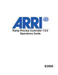
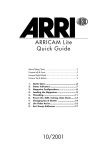
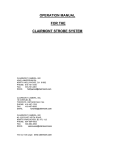
RCU-1
Instruction Manual
as of: May 1995
ALL ARTWORK, PICTURES AND TEXTS ARE COVERED BY OUR COPYRIGHT. THEY MUST NOT BE COPIED FOR REPRODUCTION (E.G. ON
CD-ROM DISKS OR INTERNET-SITES) OR USED IN THEIR ENTIRE FORM
OR IN EXCERPTS WITHOUT OUR PREVIOUS WRITTEN AGREEMENT.
IF YOU ARE DOWNLOADING PDF-FILES FROM OUR INTERNET HOMEPAGE FOR YOUR PERSONAL USE, MAKE SURE TO CHECK FOR UPDATED
VERSIONS. WE CANNOT TAKE ANY LIABILITY WHATSOEVER FOR
DOWNLOADED FILES, AS TECHNICAL DATA ARE SUBJECT TO
CHANGE WITHOUT NOTICE.
RCU-1 Operating elements
READY-LED
READY-LED
Indicator (square)
for the standard
display-mode
(RCU functions)
socket
REV
REV / FOR
operation direction switch
FOR
RUN-LED
READY
RUN
ft
m
h:min
TC UB
fpsR
sec:f
1
5
2
6
3
7
4
8
filter
jam
DISPLAY
PROG asy
end
bat
MODE
SEL / ▼
SET/▲
function
switch
MODE • SEL • SET
keys
fps
CAM
)
ramp
RCU
RCU
fps + )
ramp + )
PHASE-key
ft
m
h:min
TC UB
fpsR
sec:f
1
5
2
6
3
7
4
8
filter
jam
PROG asy
end
bat
analog to the RUN-LED on the camera
(with a slight delay due to data transfer)
MODE • SEL • SET
keys for display control
(analog to the display control on the camera)
CAM • RCU
function switch
to select between
camera display with remote control,
or RCU functions
fps
ramp
fps+ )
ramp+
)
handwheel
during the communication test,
or if the attached camera
does not respond
RUN-LED
mode selection switch
(RCU-1 functions)
)
fps
if the camera´s operating direction
is not the same as that on the RCU-1,
or if the communication is interrupted
operation direction switch
RUN-key
RCU-1
red
REV / FOR
mode selection
switch
RAMP
communication has been established,
and a valid camera is recognised
flashes red
RAMP-key
PHASE
green
)
PHASE
RUN
RAMP
keys for camera control
handwheel
to adjust camera speed
and shutter angle manually
Remote Control Unit – 1
Safety Specifications
• In order to assure optimum performance,
it is essential to read this instruction manual.
Warning signs indicate
the possibility of operational error
or equipment damage!
• Assembly and initial operation should be carried
out only by persons who are already familiar
with the equipment!
• The warning signals in the display of the RCU-1
must be obeyed, please correct the settings of
values if necessary.
(see chapter 6 – Warning Signs)
• Use only original ARRI replacement parts
and accessories!
• Product Specifications
In case of enquiries or when ordering parts,
please advise product identification number
and type designation.
1
Remote Control Unit – 1
Contents
Safety Specifications ............................ 1
1. The System ........................................ 4
Range of Functions .................................. 5
2. Setup .................................................. 8
2. 1 Electrical Connection ......................... 8
2. 2 Switching on .................................... 9
2. 3 Important Notes ............................... 9
3. CAM Functions ................................ 11
4. RCU Functions ................................. 12
4. 1 ) ................................................ 13
Adjusting the shutter angle
with the handwheel ............................... 13
Defining end-stops for the handwheel
(shutter angle) ....................................... 14
4. 2 fps ................................................ 16
Adjusting the filming speed
with the handwheel ............................... 16
Defining end-stops for the handwheel
(filming speed) ...................................... 17
4. 3 ramp ............................................. 19
Recall an automatically
controlled speed ramp
with a user-defined ramping-time ............. 19
Selecting the start and the end value
for the filming speed .............................. 20
Entering the ramp duration ..................... 21
Checking the screen-time ........................ 23
2
Remote Control Unit – 1
4. 4 fps + ) ........................................ 24
Adjusting the filming speed
with an automatically synchronised
change of the shutter angle
for constant exposure ............................. 24
Defining end-stops for the handwheel
(filming speed) ...................................... 25
Checking the shutter angle value limits ..... 27
4. 5 ramp + ) ..................................... 28
Recall an automatically controlled
speed ramp with a synchronised change
of the shutter angle
for constant exposure ............................. 28
Selecting the start and the end value
for the filming speed .............................. 29
Checking the shutter angle value limits ..... 29
Entering ramp duration .......................... 30
Checking the screen-time ........................ 31
5. Reverse Operation ........................ 33
6. Warning Displays .......................... 34
Standard Display Mode .......................... 34
All Modes ............................................. 35
7. Trouble Shooting ........................... 36
8. Technical Data ................................ 37
3
Remote Control Unit – 1
1. The System
The RCU-1 is a practical remote-control and program unit for all new-generation ARRIFLEX cameras:
from the ARRIFLEX␣ 16SR␣ 3 through the 535 and
535B to the new ARRIFLEX␣ 435.
Its range of functions is automatically adapted to the
attached camera: at both operating speed value
limits and on an electronically adjustable mirror
shutter. The RCU-1 can be used whenever uncomplicated, sturdy, and yet still comprehensive remote
control is important.
With the RCU-1 the synchronisation of the filming
speed with the opening angle of the shutter provides
an easy exposure compensation. Complete programs can be created to control the co-ordinated
change of speed and opening sector over a chosen
period of time. These programs may be recalled by
the push of a button whenever needed. The RCU-1
also automatically calculates the actual screen-time
for all programmed ramping functions.
An optimal control and precise adjustment of values
is easy with the big handwheel. The free programming of its end stops to individually defined minimum and maximum values is also extremely
comfortable.
An illuminated liquid crystal display accurately and
comprehensively shows the set values and the
camera status with all warning indicators.
4
Remote Control Unit – 1
Range of Functions
The RCU-1 combines two modes of operation in a
compact housing:
• CAM-functions
In the CAM-mode exactly the same operational
modes and functions are accessible as directly
on the camera itself. The display of the RCU-1
shows the same information as the camera display. The keys MODE, SEL, SET, RUN, RAMP
and the RUN-LED have the same function as the
equivalent operating elements on the camera.
In this mode the RCU-1 serves as a pure remote
control without its own programming possibilities.
• RCU-functions
Additionally the RCU-1 offers easy programming
and a convenient manual setting of filming speed
and shutter angle.
5
Remote Control Unit – 1
RCU-1 operating modes are:
)
to control the shutter angle manually with the
handwheel on cameras with an electronically
adjustable mirror shutter.
The end-stops for the handwheel can be programmed to cover a user-defined range of the
shutter angle.
fps
for the direct control of the filming speed with
the handwheel.
The end-stops for the handwheel can be programmed to cover a user-defined range of filming
speeds.
ramp
for the easy programming and the recall of
automatically controlled speed ramps
with a user-defined ramp duration.
fps + )
for a manual control of the filming speed with the
handwheel and an automatically synchronised
mirror shutter adjustment for constant exposure.
The end-stops for the handwheel can be programmed to cover a user-defined range of filming
speeds.
ramp + )
to program and recall automatically controlled
speed ramps with a user defined ramping-time
and an automatically synchronised shutter angle
adjustment for constant exposure.
6
Remote Control Unit – 1
In RCU mode, the display of the RCU-1 shows the
current values of the correspondent RCU modes.
The MODE, SEL, SET and RAMP key relate only
to the chosen RCU function. The available ranges
for filming speed and shutter angle are automatically recognised and supported for all connected
ARRIFLEX cameras.
• The Iris Control Unit (ICU) may be used for
cameras without electronically controlled
mirror shutters for constant exposure in the
ramp function.
7
Remote Control Unit – 1
2. Setup
2. 1 Electrical Connection
The RCU-1 is connected to the CCU-socket on the
camera with the cable KC-39 (1.5 m), or the cable
KC-41 (20 m). This serial RS 232 interface transfers
all data precisely and is not sensitive to interference.
KC-20
NC 24/7
8
KC-39
RCU-1
Remote Control Unit – 1
2. 2 Switching on
The RCU-1 does not have its own on/off switch. It
is supplied directly through the camera via the connection cable, as soon as the camera is switched on.
The display of the RCU-1 illuminates red as long,
as the camera is on.
The READY-LED changes from blinking red to permanent green, once the communication has been
successfully established. The RCU-1 is now ready
for use.
2. 3 Important Notes
• Do not edit speed values on the camera, when
operating in the RCU mode, as these values are
going to be constantly overridden by the RCU-1.
The RCU-1 is an active unit, and its settings are
predominant to the settings of the camera. The
camera retains the values which had been set
with the RCU-1. This applies for switching back
from RCU to CAM mode, as well as if the RCU-1
is disconnected from the camera.
• All selected parameters, programs and user defined end-stops are stored in the RCU-1 even if it
is disconnected. Therefore it is possible that user
defined end-stops programmed into the RCU-1
are not available with a currently connected
camera – i. e. end-stops have been programmed
for a highspeed camera and the RCU-1 is later
used on a regular production camera. The RCU-1
automatically recognises the connected type of
camera, but does not automatically change programmed values.
9
Remote Control Unit – 1
If the set values exceed the available range for
the currently connected model, a warning
indication is displayed.
Important:
In RCU-mode the RCU-1 overrides the
values for filming speed and shutter angle
set at the camera. This may result in a
wrong exposure for the subsequent takes
if the values are not checked before you
go on filming.
A value for the shutter angle set with the
RCU-1 is retained in the camera. The shutter
angle will not be automatically readjusted
to 180°.
All ramp functions programmed with the RCU-1 are
stored directly in the remote control unit, and not in
the camera. The RAMP-function is therefore not
identical with the program-function on the camera.
It is also different from a program edited with the
CCU and stored in the camera afterwards.
Do not use the Iris Control Unit (ICU) simultaneously with the RCU-1 in RCU mode
on a camera with an electronically adjustable mirror shutter. This may cause incorrect exposure.
Disconnect the ICU before using the RCU-1.
10
Remote Control Unit – 1
3. CAM Functions
CAM
RCU
position CAM
The operating elements on the RCU-1 control the
same functions as the correspondent keys and indicators on the camera:
MODE • SEL • SET • PHASE, RUN-key
and RUN-LED.
The RAMP key represents the “program“-function
of the camera in this mode of operation.
All camera functions are explained in the
corresponding instruction manuals of the cameras.
In CAM position the display of the RCU-1 shows
exactly the same information as the display on
the camera.
It is highly recommended to switch the
RCU-1 into the CAM position before
connecting it to the camera, if only CAM
functions are used. This ensures that no
filming speed or shutter angle set on the
camera is overridden in switch-position
PS/CCU on the camera and in RCU
mode on the RCU-1.
In RCU mode the RCU-1 overrides all
settings of the camera for these values.
(see Important Notes).
Ramping programs, stored in the camera
with a CCU are not affected.
11
Remote Control Unit – 1
4. RCU Functions
CAM
RCU
position RCU
In this mode the RCU-1 offers convenient access
to camera functions and an especially fast setting
of operational parameters, as well as additional
programming features.
• Change to RCU with the function switch.
• The sliding switch on the camera must be set from
NORM to PS/CCU. This enables the remote
control of the camera with the RCU-functions.
fps
The display of the RCU-1 keeps on blinking with the
warning signal “not PSCCU“, as long as the camera
is not switched to PS/CCU and therefore not ready
for remote control.
On the ARRIFLEX 535A the fps-switch is set to “CCU“
by using a coin.
12
Remote Control Unit – 1
4. 1
fps
)
)
RCU
ramp
fps + )
ramp + )
mode selection switch set to
)
Adjusting the shutter angle
with the handwheel
For cameras with an electronically adjustable
mirror shutter it is extremely convenient to control
the shutter angle with the RCU-1 manually.
• Set the mode selection switch to ) .
The display of the RCU-1 shows the value of
the currently selected and active shutter angle
together with the mode description “AnGLE“.
• The shutter angle can now be directly controlled
with the handwheel.
The adjustment range of the handwheel
may already be limited by a previously
user-defined selection
(see defining end-stops for the handwheel).
13
Remote Control Unit – 1
Cameras without an electronically adjustable mirror
shutter of course do not support this function. As a
warning signal for the user the display of the RCU-1
indicates: “no AdJ“.
Defining end-stops for the handwheel
(shutter angle)
The values for the left and the right end-stop of the
handwheel can be set to cover a user-defined
range of the shutter angle. This enables an extremely
sensitive and also precise setting of values within
the whole rotation-angle of the handwheel.
• Depress the MODE key on the RCU-1 once to
enter the editing mode.
• Then depress the SEL key for approximately 2
seconds, until a part of the display starts blinking.
Only the blinking positions can be adjusted with
the handwheel.
• With the repeated depression of the SEL key the
subsequent positions for the values can be edited
one after the other to match the requested range
for the shutter angle. It is not necessary to enter
the minimum value at the first position and then the
maximum. The lower value will be automatically
assigned to the left end-stop as the minimum.
• The selected values are stored in the RCU-1 with
the SET key.
14
Remote Control Unit – 1
• Return to the standard display by depressing the
MODE key. As an immediate indicator and a
working aid a small rectangle is integrated into
the display to mark up the standard display
mode.
Warning:
In RCU-mode the RCU-1 overrides the
values for filming speed and shutter angle
previously set on the camera.
To avoid wrong exposure, check the active
values before starting the next take.
A shutter angle set with the RCU-1 is
retained in the camera and will not be
automatically readjusted to 180°.
15
Remote Control Unit – 1
4. 2 fps
fps
)
ramp
RC
U
fps + )
ramp + )
mode selection switch set to fps
Adjusting the filming speed
with the handwheel
• Set the mode selection switch to fps.
The display of the RCU-1 shows the value of the
currently selected and active filming speed together with the mode description “SPEEd“.
• The filming speed can now be directly controlled
with the handwheel.
fpsR
The adjustment range of the handwheel may already
be limited to a previously user-defined selection
(see defining end-stops for the handwheel).
The display of the RCU-1 will blink with the warning
“SPEEd rAnGE“ when a previously defined selection
exceeds the available range for the currently connected camera. The end-stops must be corrected to
match the active camera (see Important Notes).
16
Remote Control Unit – 1
fpsR
Warning:
In RCU-mode the RCU-1 overrides the
values for filming speed and shutter angle
previously set on the camera.
To avoid wrong exposure, check the active
values before starting the next take.
i. e. if you only reset the RCU-1to the
CAM-mode, the filming speed previously
selected with the RCU-1 still remains active
on the camera.
Defining end-stops for the handwheel
(filming speed)
The values for the left and the right end-stop of the
handwheel can be set to cover a user-defined
range of filming speeds.
• Depress the MODE key to enter the editing mode.
• Then depress the SEL for about 2 seconds, until a
part of the display starts blinking.
Only the blinking positions can be adjusted
with the handwheel.
17
Remote Control Unit – 1
• With the repeated depression of the SEL key the
subsequent positions for the values can be edited
one after the other to match the requested range
of filming speeds. It is not necessary to enter the
minimum value at the first position and then the
maximum. The lower value will be automatically
assigned to the left end-stop as the minimum
position.
• The selected values are stored in the RCU-1 with
the SET key.
fpsR
• Return to the standard display by depressing
the MODE key.
The lower value limit is usually entered into the upper
line of the display. The lower line represents the top
limit. The values can also be selected in opposite
order. After depressing the SET key the values
will automatically be swapped. Thereby the upper
line will always represent the selected minimum.
18
Remote Control Unit – 1
4. 3 ramp
fps
)
ramp
RCU
fps + )
ramp + )
mode selection switch set to ramp
Recall an automatically
controlled speed ramp
with a user-defined ramping-time
• Set the mode selection switch to ramp.
The display of the RCU-1 shows the start value of
filming speed together with the mode description
“rA“.
The camera will start running with this filming speed
after depressing the RUN key.
PROG
fpsR
Once the camera is running, you can start the ramp
function at any desired time by depressing the
RAMP key. Then the camera’s filming speed will
change continually throughout the programmed
ramp duration, from the start value to the end value.
Another depressing of the RAMP key (while the
camera is still running) will cause the ramp function
to run in reverse order (from the end value back to
the start value). This procedure can be repeated
as often as desired within one take.
19
Remote Control Unit – 1
The RAMP key can also be again depressed before
the first ramp function has finished. Then the ramp
immediately reverses its direction and returns from
the reached filming speed back to the selected
starting speed.
There is no automatic exposure compensation connected with this ramp function. If a synchronised
adjustment of the shutter angle is required, select
the ramp + ) mode.
Warning:
Cameras with an electronically adjustable mirror shutter retain the shutter
angle set with the RCU-1. It is highly
recommended to check the shutter angle
prior to recalingl a programmed speed
ramp.
Selecting the start and the end value
for the filming speed
The start and end value for the filming speed is
entered in the same way as described in chapter
4. 2. In the ramp function the upper line represents the start value, the lower line the end value
for the filming speed. The start value might
actually be higher than the end value.
• Depress the MODE key to enter the editing mode.
• Then depress the SEL for about 2 seconds, until
part of the display starts blinking.
Only the blinking positions can be adjusted with
the handwheel.
20
Remote Control Unit – 1
• With the repeated depression of the SEL key the
subsequent positions for the values can be edited
one after the other to match the requested range
of filming speeds.
• The selected values are stored in the RCU-1 with
the SET key.
PROG
fpsR
Entering the ramp duration
• After editing the speed values depress the MODE
key again to enter the values for the ramp duration.
The display will shows the ramp duration
together with the indication “SEC“.
• Depress the SEL key for approximately 2 seconds.
The lower line of the display will begin to blink
with the indication “AUtO“.
If the SET key is now depressed, the RCU-1 automatically calculates and stores the shortest
possible ramp duration.
PROG
R
21
Remote Control Unit – 1
• If a specific ramp duration is required, depress
the SEL key again.
The positions of the seconds value which can be
edited with the handwheel will blink in the lower
line. The upper line shows the corresponding
screen-time that is automatically calculated for
the selected ramp duration.
By again depressing the SEL key, the position
for tenths of seconds can also be edited.
• Finish entering the ramp duration with the SET key.
PROG
Warning:
If the manually entered ramp duration is
less than the technically available
shortest ramp duration, the display of the
RCU-1 will begin to blink in the upper line
with the indication “SEC”. The selected
ramp function is technically not feasible.
If this warning is ignored, and the incorrect
ramp duration is stored in the RCU-1, the
standard display will begin to blink with
the warning “SEC rAnGE“
The READY-LED will blink green.
A ramp function can not be started.
Correct the ramp duration.
PROG
fpsR
22
Remote Control Unit – 1
Checking the screen-time
Screen-time is the time (in seconds) needed for a
projection at 24 fps. It is automatically calculated
from the start- and end-value of the filming speed
and the chosen ramp duration.
• After entering the ramp duration, depress the
MODE key again to display the screen-time.
PROG
R
The screen-time can not be edited in this display
mode. It serves as supplementary information.
• By again depressing the MODE key, return to the
standard display with the indication “rA“ and
the start value of the filming speed.
The editing of the ramp parameters is completed.
23
Remote Control Unit – 1
4. 4 fps +
fps
)
)
ramp
U
RC
fps + )
ramp + )
mode selection switch set to fps +
)
Adjusting the filming speed
with an automatically synchronised
change of the shutter angle
for constant exposure
• Set the mode selection switch to fps + ) .
The display of the RCU-1 shows the currently
selected values for the shutter angle in the upper
line, and for the filming speed in the lower line.
• The filming speed can now directly be controlled
with the handwheel.
fpsR
For cameras without an electronically adjustable
mirror shutter the following warning is indicated on
the display:
fpsR
24
Remote Control Unit – 1
In this mode the shutter angle is synchronised to the
change of the filming speed for a constant exposure.
The shutter angle of 180° is automatically assigned
to the upper filming speed value.
The constant exposure time is calculated from the
maximum filming speed value and the shutter angle
of 180°, which is assigned to this speed value:
General Rule
exposure time =
1
highest filming speed x 2
For example: Highest filming speed = 50 fps,
gives 1/100 second exposure time. This exposure
time is now valid for all selectable filming speeds.
Defining end-stops for the handwheel
(filming speed)
End-stops which had been previously defined in the
fps mode are automatically used for this mode.
New end-stops can also be defined as described
in 4. 2. Usually the upper line represents the lower
filming speed limit, the lower line the upper limit.
• Depress the MODE key to enter the editing mode.
• Then depress the SEL for about 2 seconds, until
a part of the display starts to blink.
Only the blinking positions can be adjusted with
the handwheel.
25
Remote Control Unit – 1
• With the repeated depression of the SEL key the
subsequent positions for the values can be edited
one after the other to match the requested range
of filming speeds. It is not necessary to enter the
minimum value at the first position and then the
maximum. The lower value will be automatically
assigned to the left end-stop as the minimum
position.
• The selected values are stored in the RCU-1 with
the SET key.
fpsR
If the selected speed range can not be
exposure-compensated with the shutter
angle (i.e. the speed range is too wide),
the READY-LED will blink green. In the
standard display the warning
“AnGLE rAnGE“ is indicated.
fpsR
26
Remote Control Unit – 1
Checking the shutter angle value limits
After editing the speed range, the RCU-1 automatically calculates the shutter angle which is assigned
to the lower filming speed limit.
• Depress the MODE key again.
In the upper line of the display the value for the
shutter angle assigned to the lowest speed will be
indicated. In the lower line, the angle assigned
to the highest speed. The angle values can not be
edited.
Note:
The ramp-function fps + ) and ramp
+ ) of the RCU-1 can also be used for
the ARRIFLEX 535.
In case the achieved speed change
should be faster than 6B/s it is advisable
to use the CCU-1 for a better exposure
compensation.
27
Remote Control Unit – 1
4. 5 ramp +
)
ramp
RCU
fps
)
fps + )
ramp + )
mode selection switch set to ramp +
)
Recall an automatically controlled
speed ramp with a synchronised
change of the shutter angle
for constant exposure
Additional to the ramp-function this mode provides
an exposure compensation (constant exposure time)
through the automatically synchronised change of
the shutter angle. For detailed information refer to
the ramp-function (chapter 4. 3).
The constant exposure time is calculated according
to the General rule, described under fps + )
(see 4. 4).
• Set the mode selection switch to ramp + ) .
The display of the RCU-1 indicates the start value
of the filming speed in the lower line. The upper
line shows the shutter angle which is assigned to
this starting value.
These are the parameters the camera will start with
after depressing the RUN key.
PROG
fpsR
28
Remote Control Unit – 1
Cameras without an electronically adjustable mirror
shutter of course do not support this function.
A warning signal is indicated an the display:
PROG
fpsR
Selecting the start and the end value
for the filming speed
• Select the start and the end value for the required
speed ramp.
The programming of the parameters is extensively
explained in chapter 4. 3. If values had already
been selected in this mode, the RCU-1 uses these
settings automatically to define the start and the end
value of the filming speed.
Checking the shutter angle value limits
• Depress the MODE key to display the shutter
angle values, the RCU-1 automatically calculates
for the exposure compensation.
The upper line shows the shutter angle assigned
to the start speed, the lower line the corresponding
value for the end speed of the programmed
ramp function. The angle values can not be edited.
The display serves as supplementary information.
PROG
R
29
Remote Control Unit – 1
In case the start and the end values of the
filming speed define a range that can no
longer be compensated with the shutter
angle the READY-LED starts to blink green
as a warning.
The standard display indicates the
warning “AnGLE rAnGE“.
fpsR
Entering ramp duration
• After checking the angle value limits another depressing of the MODE key takes the display to
the editing of the ramp duration.
The values are programmed as described in
chapter 4. 3 “Entering ramp duration“.
• Due to the exposure compensation with the shutter
angle, a longer ramp duration might be necessary,
as compared to the plain ramp function.
30
Remote Control Unit – 1
Checking the screen-time
• Depress the MODE key once more to display the
screen-time for the programmed speed ramp with
exposure compensation. Screen-time is the time
(in seconds) needed for a projection at 24 fps.
It is automatically calculated from the start- and
end-value of the filming speed and the selected
ramp duration.
PROG
The screen-time can not be edited. The display
serves as supplementary information. Leave the
edit mode by depressing the MODE key, and
return to the standard display.
All parameters are now programmed and stored
in the RCU-1.
Note:
The ramp-function fps + ) and ramp
+ ) of the RCU-1 can also be used for
the ARRIFLEX 535.
In case the achieved speed change
should be faster than 6B/s it is advisable
to use the CCU-1 for a better exposure
compensation.
31
Remote Control Unit – 1
32
Remote Control Unit – 1
5. Reverse Operation
Reverse operation is easily set with the REV / FOR
operation direction switch. On the ARRIFLEX 535B
and 435 cameras, all RCU functions can be used
without restriction in reverse operation.
• The ARRIFLEX␣ 535A supports via the RCU-1 only
-25 fps in reverse operation. The filming speed
in reverse operation can not be adjusted with the
RCU-1.
The ) function might be used without restriction.
The display will blink with the warning: “OnLY 25“.
If 24 fps are required in reverse operation with
the ARRIFLEX 535A, the CCU must be used to
set this filming speed.
fpsR
Reverse operation is not possible with the
ARRIFLEX␣ 16SR␣ 3.
The display of the RCU-1 blinks with the “R“
symbol as a warning, and the READY-LED
illuminates red.
The camera can be started with the RCU-1,
but will only run in the regular forward
operation direction.
33
Remote Control Unit – 1
6. Warning Displays
Special warnings are only displayed for the RCU
functions, i. e. if the necessary conditions for a particular function are not present or an entered or
stored value limit is not possible for the camera in
use. For the CAM functions only the regular
warnings as with the camera display are indicated.
There are no extra warnings for these functions.
Symbols or signs highlighted by blinking always
mean a warning. The only exceptions are the
highlighting of the positions to be changed in the
editing modes and the word “Auto“ for the
automated calculation of values.
Standard Display Mode
The speed selection switch
is not at PS/CCU
(respectively at CCU
with the ARRIFLEX␣ 535A).
fps
PROG
fps
PROG
fpsR
34
A VSU or ESU is connected
to the camera.
The functions of the RCU-1 are overlapping with the VSU or ESU.
Warning:
Operational errors are possible!
A SCU is connected to the camera.
The functions of the RCU-1 are overlapping with the SCU.
Warning:
Operational errors are possible!
Remote Control Unit – 1
The edited speed is outside the
available range.
fpsR
The edited shutter angle or the automatically calculated and stored angle
is now out of the available range.
fpsR
PROG
fpsR
The edited ramp duration is technically
not possible
(i. e.: the change of the shutter angle
is more than 55°/second)
The connected camera does not
employ an electronically adjustable
mirror shutter.
On the ARRIFLEX␣ 535A reverse
operation with the RCU-1 is only
available at -25 fps (see Reverse
Operation).
fpsR
All Modes
The
)
or fps Symbol blinks
The edited or calculated values are outside the
available range. Blinking only occurs in the display
modes in which the relevant symbol appears.
Remedy: edit again.
35
Remote Control Unit – 1
7. Trouble Shooting
The RCU-1 does not switch on
despite the camera being on
Problem
• it is dirty
• the operation direction
of the camera and the RCU-1
are not alike
• communication to the camera
is disturbed
• RCU-1 is defective
• accessory fuse on the camera
is defective
• cable KC-39 or KC-41 is defective
Cause
• repair
• remove handwheel with an
Inbus 1.3 mm and clean,
the adjustment will not be lost
• 16SR 3 reverse operation
is not possible
• check switch position PSCCU
or CCU
• replace cable KC-39 or KC-41
• have the RCU-1 repaired
• replace fuse
• replace cable KC-39 or KC-41
Remedy
Handwheel sticks or chafes
The READY-LED on the RCU-1
flashes red or turns red
• it is mechanically deformed
36
Remote Control Unit – 1
8. Technical Data
Measurements ............. 178 x 70 x 62 mm
(l x w x h)
Weight ....................... 0.54 kg (without cable)
Power supply .............. 24 V= (18 ... 32 V)
Power consumption ...... approx. 45 mA
Data interface ............. RS-232
Pin assignment:
Pin 1: ............. TXD-RCU
Pin 2: ............. RXD-RCU
Pin 3: ............. + 24 V Standby
Pin 4: ............. Shield
Pin 7: ............. Ground (0 V)
remaining pins free
Handwheel
rotation angle ............. mechanically ... 150°
electrically ....... 145°
Resolution ................... filming speed
> 100 fps ....... 0,01 fps
< 100 fps ....... 0,001 fps
shutter angle .... 0,1°
Connecting cable ......... Type: KC-39
ID NR: K4.47329.0
Length: 1.5 m
optional:
Type: KC-41
ID NR: K2.47350.0
Length: 20 m
Identnumber RCU-1 ...... K2.47197.0
37
ARRI Service
ARRI SERVICE
Germany ................. Arnold & Richter Cine Technik
Türkenstraße 89
D-80799 München
phone: (089) 3809-0
fax: (089) 3809-1244
fax service: (089) 3809-1793
E-mail service: [email protected]
USA .......................... ARRI USA
617, Route 303
Blauvelt, New York 10913
phone: (914) 353 14 00
fax: (914) 425 12 50
E-mail: [email protected]
ARRI USA
600 North Victory Blvd.
Burbank, California 91502
phone: (818) 841 70 70
fax: (818) 848 40 28
E-mail: [email protected]
GB ............................ ARRI (GB) Ltd.
The Movie House
1-3 Airlinks, Spitfire Way
phone: (0208) 848 88 81
fax: (0208) 561 13 12
E-mail: [email protected]
ARRI Service
Italy .......................... ARRI ITALIA S.R.L.
Viale Edison 318
20099 Sesto S. Giovanni (Milano)
Tel.: (02) 26 22 71 75
Fax: (02) 242 16 92
E-mail: [email protected]
ARRI ITALIA S.R.L.
Via Placanica, 97
00040 Morena (Roma)
phone: (06) 79 89 02 02
fax: (06) 79 89 02 39
Canada .................... ARRI Canada Ltd.
415 Horner Avenue, Unit 11
Etobicoke, Ontario
Canada M8W 4W3
phone: (416) 255 33 35
fax: (416) 255 33 99
E-mail: [email protected]
Remote Control Unit – 1
© ARRI/KVW
Technical data is subject to change without notice
RD 601 03 0595
Printed in Germany
Identnumber for Instruction Manual:
K5.44000.0
Available languages
German
English
ARNOLD & RICHTER
CINE TECHNIK
TÜRKENSTR. 89 • D-80799 MÜNCHEN • TEL. (089) 3809-0
FAX (089) 3809 - 1244 • http://www.arri.com
38