1
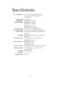
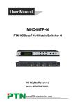
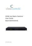
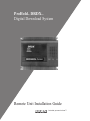
ProHold DRDX
Digital Download System
TM
TM
Remote Unit Installation Guide
Just what you want to hear™
FCC Notice
This equipment has been tested and found to comply within the limits for a
Class A digital device, pursuant to Part15 of FCC rules. These limits are
designed to provide reasonable protection against harmful interference in a residential installation. This equipment generates, uses and can radiate radio frequency energy and, if not installed and used in accordance with the instructions,
may cause harmful interference to radio communications.
There is no guarantee that interference shall not occur in a particular installation. If this equipment does cause harmful interference to radio (and) or television reception, which can be determined by turning the equipment on and off,
and noting any change in said interference, the user is encouraged to try to correct the interference by one or more of the following measures:
• Reorient or relocate the receiving antenna.
• Increase the separation between the equipment and receiver.
• Connect the equipment into an outlet on a circuit different from that to
which the receiver is connected.
• Consult the dealer or an experienced radio/TV technician for assistance.
This Class A digital apparatus meets all requirements of the Canadian
Interference-Causing Equipment Regulations
Cet appareil numérique de la classe A respecte toutes les exigences du
Règlement sur le matériel brouilleur du Canada.
FCC Requirements
1. The Federal Communications Commission (FCC) has established Rules
which permit this device to be directly connected to the telephone network.
Standardized jacks are used for these connections. This equipment should
not be used on party lines or coin lines.
2. If this device is malfunctioning, it may also be causing harm to the telephone
network; this device should be disconnected until the source of the problem
can be determined and until repair has been made. If this is not done, the
telephone company may temporarily disconnect service.
3. The telephone company may make changes in its technical operations and
procedures; if such changes affect the compatibility or use of this device, the
telephone company is required to give adequate notice of the changes.
4. If the telephone company requests information on what equipment is connected to their lines, inform them of:
(a) The telephone number that this unit is connected to,
(b) the ringer equivalence number: 0.2B
(c) The USOC jack required [RJ11C], and
(d) The FCC registration Number
Items (b) and (d) are indicated on the label. The ringer equivalence number
(REN) is used to determine how many devices can be connected to your
telephone line. In most areas, the sum of the RENs of all devices on any
one line should not exceed five (5.0). If too many devices are attached,
they may not ring properly.
Service Requirements
5. In the event of equipment malfunction, all repairs should be performed by
our Company. It is the responsibility of users requiring service to report the
need for service to our Company or one of our authorized agents. Service
can be facilitated through our office at: Bogen Communications, Inc., 50
Spring Street, Ramsey, NJ 07446 Phone: (201) 934-8500.
Warning: Changes or modifications to this unit not expressly approved by the party
responsible for compliance could void the user’s authority to operate the equipment.
© 1997 Bogen Communications, Inc.
50 Spring St., Ramsey, NJ 07446
All rights are reserved. No part of this document may be photocopied, reproduced, or
translated to another language without the prior written consent of Bogen
Communications Inc.
Notice: The information contained in this document is subject to change without notice
and should not be construed as a commitment by Bogen Communication, Inc.
Bogen Communications Inc. assumes no responsibility for any errors that may
appear in this document nor does it make expressed or implied warranty of any
kind with regard to this material, including, but not limited to, the implied warranties of merchantability and fitness for a particular purpose.
Bogen Communications Inc. shall not be liable for incidental or consequential damages
in connection with, or arising out of the furnishing, performance, or use of this document and the equipment which is describes.
Part No. 54-5033-01
June, 1997
Printed in Korea
Important Safety Instructions
1. Read and follow all instructions.
2. Follow all warnings and instructions marked on the product
3. Unplug the product from the wall outlet before cleaning. Do not use liquid cleaners or aerosol
cleaners. Use a damp cloth for cleaning.
4. Do not use this product near water, for example, near a bath tub, wash bowl, kitchen sink, or
laundry tub, in a wet basement, or near a swimming pool.
5. Do not place this product on an unstable cart, stand or table. The product may fall causing
serious damage to the product.
6. Slots and openings in the cabinet and the back or bottom are provided for ventilation, to protect
it from overheating, these openings must not be blocked or covered. The openings should
never be blocked by placing the product on the bed, sofa or other similar surface. The product should never be placed near or over a radiator or heat register. This product should not
be placed in a built-in installation unless proper ventilation is provided.
7. This product should be operated only from the type of power source indicated on the marking
label. If you are not sure of the type of power supply, consult your dealer or local power company.
8. The power supply included with this product has a 2-prong plug for connection with a standard
electrical outlet.
9. Do not allow anything to rest on the power cord. Do not locate this product where the cord will
be abused by persons walking on it.
10. Do not overload wall outlets and extension cords as this can result in the risk of fire or electrical shock.
11. Never push objects of any kind into this product through cabinet slots as they may touch dangerous voltage points or short out points that could result in a risk of fire or electric shock.
Never spill liquid of any kind on the product.
12. To reduce the risk of electric shock, do not disassemble this product, but return it to the factory
service center when some service or repair work is required. Opening or removing covers
may expose you to dangerous voltages or other risks. Incorrect assembly can cause electric
shock when the product is subsequently used.
13. Unplug this product from the wall and refer servicing to the factory service center personnel
under the following conditions:
a. When the power supply cord or plug is damaged or frayed.
b. If liquid has been spilled into the product.
c. If the product has been exposed to rain or water.
d. If the product does not operate normally by following the operating instructions. Adjust
only those controls that are covered by the operating instructions because improper adjustment of other controls may result in damage.
e. If the product has been dropped or the cabinet has been damaged.
f. If the product exhibits a distinct change in performance.
14. Avoid using a telephone during an electrical storm. There may be a remote risk of electric
shock from lightning.
15. Do not use the telephone to report a gas leak in the vicinity of the leak.
ProHold DRDX
TM
TM
Digital Download System
DRDX Unit Installation Guide
1
Specifications
Power Requirements: 9V AC. Power supply included with the
unit provides 9V AC @ 800 mA from
110V AC Source
Coding Method: IMA Standard
Sampling Rate: 128 Kilobits/sec minimal
Memory Capacity: PRO4 DRDX - 4 minutes
PRO6 DRDX- 6 minutes
PRO8 DRDX - 8 minutes
PRO12 DRDX- 12 minutes
Memory Backup: 20 year non volatile FLASH Memory
Ext. Speaker Output: 1 watt into 8Ω via standard RCA Phono Jack
LINE Output: 600Ω transformer balanced via standard RCA
Phono Jack
AUX Input: Local Analog Pre-amp input via standard RCA
Phono Jack
External Controls: VOLUME Control (tool accessible only)
SPEAKER on/off switch
External Indicators: POWER LED - (red)
PLAY LED - (green)
LOAD LED - (green)
PSTN Connection: Standard RJ11 analog loopstart station interface
Modem Line Speed: 33.6 KBPS basic rate + MNP5/V.42 bis
Compression/ECC
Mounting: Wall or Desk Top
Dimensions: 7” x 10” x 3.5”
Shipping Weight: 1.6kg./4lb.
2
Contents
1.
Introduction . . . . . . . . . . . . . . . . . . . . . . . . . . . . . . . . . . . . . . . . . .4
2.
Front Panel Features . . . . . . . . . . . . . . . . . . . . . . . . . . . . . . . . . . . .5
3.
Top Panel Controls and Connections . . . . . . . . . . . . . . . . . . . . . . . .6
4.
Installation . . . . . . . . . . . . . . . . . . . . . . . . . . . . . . . . . . . . . . . . . . .7
4.1
Unpacking & Inspection . . . . . . . . . . . . . . . . . . . . . . . . . . . . . . . . .7
4.2
Installation Precautions . . . . . . . . . . . . . . . . . . . . . . . . . . . . . . . . . .7
4.3
Connecting Power Supply . . . . . . . . . . . . . . . . . . . . . . . . . . . . . . . .7
4.4
Connecting to the PSTN Network . . . . . . . . . . . . . . . . . . . . . . . . . .7
4.5
Connecting to your Telephone System . . . . . . . . . . . . . . . . . . . . . .8
4.6
Connection to an External Speaker (optional) . . . . . . . . . . . . . . . . .8
4.7
Connection to a Local Music Source (optional) . . . . . . . . . . . . . . . .8
5.
Operation . . . . . . . . . . . . . . . . . . . . . . . . . . . . . . . . . . . . . . . . . . . .9
6.
Typical Configurations . . . . . . . . . . . . . . . . . . . . . . . . . . . . . . . . . .9
6.1
Direct Connect . . . . . . . . . . . . . . . . . . . . . . . . . . . . . . . . . . . . . . . .9
6.2
Time Share . . . . . . . . . . . . . . . . . . . . . . . . . . . . . . . . . . . . . . . . . . .9
6.2.1 External Share Device . . . . . . . . . . . . . . . . . . . . . . . . . . . . . . . . . .9
6.2.2 Parallel Time Share . . . . . . . . . . . . . . . . . . . . . . . . . . . . . . . . . . . .10
6.2.3 Distinctive Ring . . . . . . . . . . . . . . . . . . . . . . . . . . . . . . . . . . . . . .10
6.3
PBX/KSU Station Line . . . . . . . . . . . . . . . . . . . . . . . . . . . . . . . . .10
7.
Troubleshooting . . . . . . . . . . . . . . . . . . . . . . . . . . . . . . . . . . . . . .11
8.
Care and Maintenance . . . . . . . . . . . . . . . . . . . . . . . . . . . . . . . . . .12
3
1. Introduction
The ProHold DRDX is the latest addition to the ProHold Series of Message On
Hold Digital Announcers form BOGEN Communications.
The ProHold Remote DRDX is designed to provide the end-user with superior
‘DDD’ Digital Message Quality, combined with flexible programming.
With ProHold DRDX there are no more lost tapes, worn out heads or gummy
capstans. ProHold DRDX is virtually maintenance free. There are absolutely no
moving parts to wear or break. In fact, once your ProHold DRDX is installed,
you may never have to touch it again. Every feature is able to be controlled
remotely.
Each ProHold DRDX unit Features:
• Full Digital Audio Quality - ‘Digital Door-to-Door’ (DDD)
• Fully Automatic On-Board Digital Mixing
• 20 year Non Volatile FLASH Audio Memory Backup
• Bogen STC (Single Track Control) - Precision Audio Editing
• Bogen B-mail Audio Delivery Software
• Instant Access Downloads - Anywhere, Anytime
• Line share with fax machine or other telco device
• Choice of 600Ω or 1 watt 8Ω output
• Choice of Digitally Recorded Music Bed or Local Analog Bed
• Built-in Monitor Speaker with on/off switch
• Status LED Indicators
• Choice of Local or Remote Volume Control
• Choice of Two Fully Independent Programs
• Time of Day Program Switching
Unit Operation is as simple as FLASH-n-PLAY! Just connect ProHold DRDX
to your PBX/KSU MOH port, plug in the PSTN line and plug the power supply into the wall. Now just call your Studio and within minutes you’re up and
running. No more waiting for the ‘snail mail’ postman!
4
2. Front Panel Features
2
1
1.
LED Indicators
POWER, PLAY and LOAD. The POWER LED is lit when unit is
plugged into wall. The PLAY LED is lit when unit is playing either
Program. The LOAD LED is lit only when the unit is communicating
with the Base Station.
2.
Monitor Speaker
Lets you monitor playback levels and locally set via the local volume
control. A SPKR ON/OFF switch is included on the top panel.
5
3. Top Panel Controls
and Connections
7
6
5
4
3
2
1
Key
Identifier
Description
1
9V AC
Jack accepts 9V AC power to the unit. The power
supply included with the unit provides 9V AC @
800mA from a 110V AC source.
2.
1 WATT
RCA Phono Jack - 1 watt into 8Ω
3
Ω
LINE 600Ω
600Ω output to the MOH input on a telephone
system or to the amplifier of a loudspeaker system
4.
AUX IN
Local analog input provides analog music bed
5
SPKR ON/OFF Speaker on/off switch - controls monitor speaker
output
6
VOLUME
Controls the output level of the monitor speaker,
LINE and 1 watt output jacks.
7
TEL LINE
Standard RJ11 Analog Station Jack - provides
remote connection services
6
4. Installation
4.1 Unpacking & Inspection
Your ProHold DRDX unit was carefully checked and inspected at the factory.
Inspect the carton and unit for signs of damage as you unpack your unit. If
damage is found, notify the dealer from whom the unit was purchased. If you
received the unit through the mail, you must file a claim with the carrier.
4.2 Installation Precautions
Please observe the following Installation Precautions:
• Do Not install the unit in damp areas, or in areas where it is likely to
be exposed to moisture.
• Do Not install the unit in areas where the ambient temperature is
likely to go below 40°F or exceed 90°F.
• Make sure to use suitable fasteners when mounting the unit on hollow walls or other similar thin materials. Plastic screw anchors are
provided.
4.3 Connecting Power Supply
Connect the output plug from the power supply included with the unit to the
9V AC jack on the rear panel of the ProHold DRDX. Plug the power supply
into any convenient 110V AC outlet.
4.4 Connecting to the PSTN
Network
Connect the RJ11 jack, (phone line jack) located on the rear panel of the
ProHold DRDX, to any convenient analog station line using the standard telephone line cable provided with the unit.
Helpful HINT: Record the number of the phone line you are connecting to
ProHold DRDX - you will need it later.
7
4.5 Connecting to your
Telephone System
Use the audio cable terminated with an RCA type plug (provided) to connect
the LINE 600Ω output or 1 watt output to your telephone system’s Messageon-Hold (MOH) input. (The outputs may also be used to feed into the input of
a loudspeaker system amplifier.)
4.6 Connection to an External
Speaker (optional)
The 1 watt output RCA Phono Jack may be used to power an external 8Ω
speaker. The output provides 1 watt into 8Ω.
4.7 Connection to a Local
Music Source (optional)
If desired a Local Preamplified Analog Music source may be connected to the
AUX IN RCA Phono Jack on the top panel of the ProHold DRDX unit. Local
music input will be optionally mixed with the stored digital audio output of the
ProHold DRDX.
Note: This option must be enabled by your Studio via the Remote Interface.
8
5. Operation
ProHold DRDX is extremely simple to operate. Once the unit has been properly installed the only action you have to perform is to call your studio and give
them the phone number of the ProHold DRDX unit.
Your studio will help you customize your production and preferences. As soon
as you give your final approval, your Message is ON LINE working for your
business. No waiting for the snail-mail express!
6. Typical
Configurations
ProHold DRDX is extremely flexible and can be configured many different
ways. Here are three typical configurations.
6.1 Direct Connect
Direct Connect is the simplest ProHold DRDX configuration. The unit PSTN
interface is connected to a direct dedicated outside line. This line is only used
for ProHold DRDX access.
6.2 Time Share
Time Share allows the ProHold DRDX to share its access line with some other
user application or equipment. There are two different flavors of this type of
connection:
6.2.1 External Share Device
In this configuration the incoming phone line is split via an external device
(Line Switch) into separate USER and ProHold lines. These lines share the
same physical number and it its the responsibility of the Line Switch to differentiate between incoming USER calls and ProHold calls. This method is highly
reliable, inexpensive and maximizes the users resource usage.
9
6.2.2 Parallel Time Share
In this configuration the incoming phone line is split via a ‘line splitter’ device.
(Available at most electronic/hardware stores). One line is physically connected
to both devices, like the phone extensions in your home. You could have your
studio set the ProHold DRDX to one (1) ring answer but restricted to Mondays
from 5:00 p.m. till 5:00 a.m. All other times the USER Equipment would actually pick up the line (user equipment should be set to pick up on 2 to 3 rings)..
6.2.3 Distinctive Ring
Using the ‘line splitter’ setup as above, the ProHold DRDX can also be optionally configured to recognize distinctive ring from the CO for incoming line
pickup. This option requires distinctive ring to be enabled on the users phone
line but has the advantage of allowing ProHold DRDX to positively answer
any time the Base Station calls.
6.3 PBX/KSU Station Line
PBX/KSU Station Line connection places the ProHold DRDX at an internal
extension attached to your PBX/Key System. This extension MUST be a standard analog phone extension with talk battery provided. The extension need not
have a direct dial number (DID), the B-mail software can find its way past
almost all auto-attendant type programs. In this case both the main phone number AND the extension must be provided to your studio.
10
7. Troubleshooting
There is virtually nothing which can fail within the ProHold DRDX unit.
Almost all unit problems can be traced to a few simple causes.
Power LED does not light
Check power supply connection. Verify wall outlet is operational (e.g. no
blown fuse or tripped breaker)
No Audio
Check VOLUME control setting
Verify Patch Cord connected to correct output RCA Jack
Verify PBX/KSU connection
If new unit, call studio to download Audio Program
Call studio to verify Program
Unit will not ‘Pick Up’ phone
Verify Phone Number of line connected to unit
Verify that line is not ‘in use’ by another device
Audio Distorted On PBX/KSU Hold Bus
Reduce Volume or change output port to either the 1 WATT or 600Ω LINE
output ports.
11
8. Care and
Maintenance
The impact resistant housing and quality construction of the ProHold DRDX
virtually eliminates the need for service or maintenance
There are No User Serviceable Components within the unit or the power supply. Refer all servicing to qualified personnel.
12
Notes
13
50 Spring Street • Ramsey, NJ 07446
(201) 934-8500
www.bogen.com