1
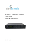
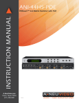
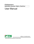
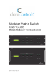
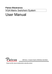
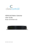
User Manual MHD44 HDMI Matrix Switcher All Rights Reserved Version: MHD44_2014V1.0 HDMI 4x4 Matrix Switcher NOTICE: Please read this user manual carefully before using this product. This manual is only for operation instruction only, not for any maintenance usage. The functions described in this version are updated till February 2014. Any changes of functions and parameters since then will be informed separately. Please refer to the dealers for the latest details. This manual is copyright PTN Electronics Limited. All rights reserved. No part of this publication may be copied or reproduced without the prior written consent of PTN Electronics Limited. All product function is valid till 2014-2-8. Update History Version 1.0 Date 2014.02.08 Update Content First version. HDMI 4x4 Matrix Switcher Table of Contents 1. Introduction .................................................................................................................1 1.1 Introduction to MHD44 ....................................................................................... 1 1.2 Features ............................................................................................................ 1 1.3 Package Contents ............................................................................................. 1 2. Product Appearance of MHD44 ..................................................................................2 2.1 Front Panel ........................................................................................................ 2 2.2 Rear Panel......................................................................................................... 3 3. System Connection .....................................................................................................3 3.1 Usage Precautions ............................................................................................ 3 3.2 System Diagram ................................................................................................ 4 3.3 Connection Procedure ....................................................................................... 4 3.4 System Applications .......................................................................................... 4 4. System Operations .....................................................................................................5 4.1 Button Control.................................................................................................... 5 4.2 IR Control .......................................................................................................... 6 4.2.1 Usage of IR Remote ................................................................................6 4.3 RS232 Control ................................................................................................... 7 4.3.1 Control MHD44 via a PC .........................................................................7 4.3.2 PC RS232 Control Software Setting ........................................................7 4.3.3 RS232 Commands ..................................................................................7 4.4 USB Firmware Updating .................................................................................. 10 5. Specification ............................................................................................................. 12 6. Panel Drawing .......................................................................................................... 12 7. Troubleshooting & Maintenance ............................................................................... 13 8. Safety Operation Guide ............................................................................................ 14 9. After-sales Service ....................................................................................................15 HDMI 4x4 Matrix Switcher 1. Introduction 1.1 Introduction to MHD44 MHD44 is a high-performance digital matrix switcher for HDMI signals, including 4 HDMI inputs, 4 HDMI outputs. It conforms to HDCP standards, supports HDMI 1.4a, and can handle 1080P 3D signal. It can be controlled via diverse and flexible control methods including front panel buttons, RS232 serial port and IR. 1.2 Features Supports HDMI 1.4a, 1080P@24Hz 3D, DVI1.0 compatible Supports 6.75Gbps bandwidth Intelligent EDID data management Supports online upgrade process via USB port on front panel LCD screen shows real-time connection status, switching status, whether input/ output signal is with HDCP, and output resolution. 1.3 Package Contents 1 x MHD44 2 x Mounting ears (6 x Black Screws) 1 x RS232 cable 4 x Plastic cushions (4 x Screws) 1 x Power adapter (12V DC) 1 x IR remote 1 x IR receiver 1 x User manual Note:Please confirm if the product and the accessories are all included, if not, please contact with the dealers. 1 HDMI 4x4 Matrix Switcher 2. Product Appearance of MHD44 2.1 Front Panel No. ① ② Name Firmware Power Indicator Description Micro USB port for update firmware. Keeps light when power on. ③ IR In-built IR receiver, receives IR signals emitted by IR remote to facilitate remote control. ④ LCD Indicator Real-time show for system status. INPUTS INPUT1 ~ 4 corresponds 4 HDMI input sources separately. Inquire mode: press “AV” more than 3 seconds to enter this mode to check connection status, switching status, whether input/ output signal is with HDCP and output resolution. Press to change different menus, to inquire resolutions of INPUT1~4. ⑤ AV: to transfer AV and IR signal synchronously by the switcher. ⑥ ⑦ FUNCTION BUTTONS OUTPUTS ALL: to transfer one input to all outputs. EDID: manually capture and study the EDID data from output device to input port. Note: Make sure signal source is set up correctly and can deliver data to display device stably. OUTPUT1 ~ 4 corresponds 4 HDMI output sources separately. 2 HDMI 4x4 Matrix Switcher 2.2 Rear Panel No. ① Name GROUND ② INPUTS ③ OUTPUTS ④ IR EYE ⑤ RS232 ⑥ Power adapting port Description Connect to grounding, make the unit ground well. 4 HDMI input ports, connect with HDMI ports of signal sources. 4 HDMI output ports, connect with HDMI ports of output source devices. Connect with IR receiver, use the IR remote to control MHD44. The serial port for unit control, 9-pin female connector, connects with control device such as a PC. (Make sure to fill in corresponding communication protocol parameters correctly.) Connect with 12V DC power adaptor. The indicator will turn red and keep light when power on. 3. System Connection 3.1 Usage Precautions 1) System should be installed in a clean environment and has a prop temperature and humidity. 2) All of the power switches, plugs, sockets and power cords should be insulated for safety. 3) All devices should be connected before power on. 3 HDMI 4x4 Matrix Switcher 3.2 System Diagram 3.3 Connection Procedure 1) Connect HDMI sources (e.g. DVD) to HDMI “INPUTS” of MHD44 with HDMI cables. 2) Connect HDMI displayers to HDMI “OUTPUTS” of MHD44 with HDMI cables. 3) Connect the RS232 port (9 pin female connector) of MHD44 to a control device with a serial cable, and control MHD44 via the control device (e.g. a PC). 4) Connect IR receiver to the IR Eye port. 5) Connect 12V DC power adaptor to MHD44. 3.4 System Applications With its good performance in control and transmission, MHD44 can be widely used in computer realm, monitoring, large screen displaying, conference system, television education and bank securities institutions etc. 4 HDMI 4x4 Matrix Switcher 4. System Operations 4.1 Button Control The operation examples are showed in 2.1 Front Panel. Here we make a brief introduction to the system inquiry operations. Use Keep pressing the button “AV” for 3 seconds, it will enter into system inquire menu. to check the previous/next item. Function Items Example Description Check the connection status of inputs Y means the corresponding port is connected with input device, N means not. Check the connection status of outputs Y means the corresponding port is connected with output device, N means not. Correspondence between inputs and outputs Shows the correspondence between the 4 inputs and 4 outputs. Check if the input is with HDCP Y means the input signal is with HDCP, N means not. Check if the output is with HDCP Y means the output signal is with HDCP, N means not. Check the output resolution Use to check all the 4 output resolutions. 5 HDMI 4x4 Matrix Switcher 4.2 IR Control 4.2.1 Usage of IR Remote Standby button, press it to enter/exit standby mode. Input channels, range from 1~4. Menu buttons, AV , ALL and EDID buttons have the same function as AV , ALL and EDID on the front panel. THROUGH: to transfer the signals directly to the corresponding output channels. Example: Press “3”, “THROUGH”, the result will be IN 3→OUT 3. Press “ALL”, “THROUGH”, the result will be: 1→1, 2→2, 3→3, 4→4. Output channels, ranges from 1~4. Note: In-built IR or extended IR receiver connected to IR Eye can control the device with this remote control. 6 HDMI 4x4 Matrix Switcher 4.3 RS232 Control 4.3.1 Control MHD44 via a PC To control MHD44, you need to connect the 9 pin female RS232 port to a PC’s RS232 port. By using RS232 control software and setting right specifications, you are able to control MHD44. 4.3.2 PC RS232 Control Software Setting Installation: Copy the control software file to the computer which is connected with HDMI Matrix Switcher. Uninstallation: Delete all the control software files in corresponding file path. Basic Settings: Firstly, connect the HDMI Matrix Switcher with all input source devices and output displaying devices needed. Then connect HDMI Matrix Switcher with a computer which is installed with RS232 control software. Note: Please set the parameters (including COM number, baud rate, data bit, stop bit and the parity bit) correctly, and then you are able to send commands. 4.3.3 RS232 Commands Communication protocol: RS232 Communication Protocol Baud rate: 9600 Command Types System Command Data bit: 8 Stop bit: 1 Command Codes Parity bit: None Functions /*Type; Inquire the models information. /%Lock; Lock the front panel buttons on the Matrix. /%Unlock; Unlock the front panel buttons on the Matrix. /^Version; Inquire the version of firmware /:MessageOff; /:MessageOn; Turn off the feedback command from the com port. It will only show the “Switch OK!”. Turn on the feedback command from the com port. 7 HDMI 4x4 Matrix Switcher Demo. Undo. [x]All. All#. All$. Transfer signals from the input channel [x] to all output channels Transfer all input signals to the corresponding output channels respectively. Switch off all the output channels. [x]$. Transfer signals from the input channel [x] to the output channel [x]. Switch off the output channel [x]. [x]@. Switch on the output channel [x]. All@. Switch on all output channels. [x]#. Status[x]. Transfer the AV signal from the input channel [x1] to the output channel [x2]. Inquire [x] output statues. Status. Inquire all outputs statues one by one. [x1] B[x2]. Recall[Y]. Save the present operation to the preset command [Y], ranges from 0 to 9. Recall the preset command [Y]. Clear[Y]. Clear the preset command [Y]. PWON. Work in normal mode. PWOFF. Enter into standby mode. Save[Y]. Operation Command Switch to the “demo” mode, 1->1, 2->2, 3->3 … and so on .The switching interval is 2 seconds. To cancel the previous operation. HDCP management command. [Y] is for input (value: I) or output (value: O). [X] is the number of one port, if the value of X is ALL, it means all ports. [Z] is for HDCP compliance status (value: 1 or 0, 1 stands for “with”, 0 stands for “without”). /%[Y]/[X]:[Z]. Y=I & Z=1, means the input port is compliant with HDCP. Y=O & Z=1, means output with HDCP. Y=I & Z=0, means the input port is not compliant with HDCP. Y=O & Z=0, means output without HDCP. %0800. Manual HDCP management. %0801. Automatically HDCP management. If input is with HDCP, so is output. 8 HDMI 4x4 Matrix Switcher EDIDH[x]B[y]. DigitAudioON[ x]. DigitAudioOF F[x]. Input port [y] learns the EDID from output port [x]. If the EDID data is effective and the audio part supports not only PCM mode, then force-set it to PCM mode. If the EDID data is not effective, then set it as initialized EDID data. Enable HDMI audio output of port x. X=1, 2, 3, 4, enable this one port. X=5, enable all the 4 ports. Disable HDMI audio output of port x. X=1, 2, 3, 4, disable this one port. X=5, disable all the 4 ports. %0911. Reset to factory default. %9961. Check the system locking status. %9962. Check the status of standby mode. %9971. Check the connection status of the inputs. %9972. Check the connection status of the outputs. %9973. Check the HDCP status of the inputs. %9974. Check the HDCP status of the outputs. %9975. Check the switching status. %9976. Check the output resolution. %9977. Check the status of digital audio of output channels. %9978. EDIDPCM[x]. EDIDG[x]. EDIDMInit. EDIDM[X]B[Y]. EDIDUpgrade [x]. Check whether the input port is compatible with HDCP Set the audio part of input port [x] to PCM format in EDID database. Get EDID data from the output and display the output port number of X. Recover the factory default EDID data. Manually EDID switching. Learn the EDID data of output[X] to the input[Y]. Upgrade EDID data via the RS232 port [X] is for input port, when the value of X is 5, it means to upgrade to all input ports. When the switcher gets the command, it will show a message to send EDID file (.bin file). Operations will be canceled after 10 seconds. (Note 1) Please cut off all connections of HDBaseT ports. 9 HDMI 4x4 Matrix Switcher Select one type of EDID data and upgrade built-in EDID data. Supports 4 types of EDID data: UpgradeIntED ID[x]. 1. 1080P, 2D, PCM2.0 2. 1080P, 2D, 5.1 (audio) 3. 1080P, 3D, PCM2.0 4. 1080P, 3D, 5.1 (audio) [x] = 1, 2, 3 or 4 When the switcher gets the command, it will show a message to send EDID file (.bin file). Operations will be canceled after 10 seconds. EDID/[x]/[y]. Set the built-in EDID data of input port [x] to type [y]. The value of [y] is 1, 2, 3, and 4. The EDID data types are same as mentioned above. Note: 1. Please disconnect all the twisted pairs before sending command EDIDUpgrade[X]. 2. In above commands, “[”and “]” are symbols for easy reading and do not need to be typed in actual operation. 3. Please remember to end the commands with the ending symbols “.” or “;”. 4. Type the command carefully, it is case-sensitive. 4.4 USB Firmware Updating To meet with the request of different users or additional functions in future, the firmware of MHD44 can be upgraded via USB. When you need to upgrade it, please download the latest upgrade file and then you are able to upgrade it through the update EXE software. Copy the EXE software to the PC in controlled and double click the program to upgrade the firmware. When the program is running normally, it will enter into the interface (as shown in next figure), please press the button Open and choose the upgrade file downloaded, and then press the button Updata. Then it starts to upgrade. When all are done, it will appear with a dialog box showing the message Update success. 10 HDMI 4x4 Matrix Switcher Note: The COM number connected with PC is available only when in 1 to 9. 11 HDMI 4x4 Matrix Switcher 5. Specification Video Input Input Input Connector Input Level Input Impedance Video General Gain 4 HDMI A Type Female HDMI T.M.D.S. 2.9V/3.3V 100Ω (Differential) 0 dB Video Signal HDMI (or DVI-D) Resolution Range Up to 1920 x 1200@60Hz or 1080P@60Hz Video Output Output Output Connector Output Level Output Impedance Bandwidth Maximum Pixel Clock Switching Speed 4 HDMI A Type Female HDMI T.M.D.S. 2.9V/3.3V 100Ω (Differential) 6.75Gbit/s 225MHz 200ns (Max.) EDID In-built EDID data and manual EDID management Management HDCP Supports HDCP 1.3, auto and manual HDCP management. Control Parts 1 IR EYE (black) Control Ports Panel Control Front panel buttons 1 RS232 (9 pin female D) IR Default IR remote General W482.6 x H43.9 x Power Case DC12V,2A D236.5mm (1U high, Supply Dimension full rack wide) Temperature -20 ~ +70℃ Humidity 10% ~ 90% 6. Panel Drawing 12 HDMI 4x4 Matrix Switcher 7. Troubleshooting & Maintenance 1) When there is a color losing or no video signal output, maybe the cables have already broken or haven’t been connected well. 2) When EDID management does not work normally, probably the HDMI cable is broken at the output end. 3) When switching, there is a blank screen on the displayer, maybe the displayer does not support the resolution of the video source. Switch again or manage the EDID data manually to make the resolution of the video source automatically compliant with the output resolution. 4) When user cannot control the switcher by computer through its COM port, please check the COM port number in the software, and make sure the COM port is in good condition and the communication protocol is correct. 5) When switching , there is no output image: Check if there is any signal at the input. Check if there is any signal at the output. If there is no signal input/output, maybe the input/output cables broken or the connectors loosen, please change for another cable. Check if the output port number is the same with the controlled one. If it is still the same after the above checking, maybe there is something wrong in the switcher. Please send it to the dealer for repairing. 6) If the static becomes stronger when connecting the video/audio connectors, it probably due to bad grounding, please check the grounding and make sure it connected well; otherwise it would damage the switcher. 7) If the switcher cannot be controlled through the RS232 port, front panel buttons or by the IR remote, the unit may have already been broken. Please send it to the dealer for repairing. 13 HDMI 4x4 Matrix Switcher 8. Safety Operation Guide In order to guarantee the reliable operation of the equipments and safety of the staff, please abide by the following proceeding in installation, using and maintenance: 1) The system must be earthed properly. Do not use two blades plugs and ensure the alternating power supply ranged from 100v to 240v and from 50Hz to 60Hz. 2) Do not put the switcher in a place of too hot or too cold. 3) As the power generating heat when running, the working environment should be maintained fine ventilation, in case of damage caused by overheat. 4) Cut off the general power switch in humid weather or left unused for long time. 5) Before following operation, ensure that the alternating current wire is pull out of the power supply: Take off or reship any components of the equipment. Take off or rejoin any pin or other link of the equipment. 6) As to non-professional or without permission, please DO NOT try to open the casing of the equipment, DO NOT repair it on your own, in case of accident or increasing the damage of the equipment. 7) DO NOT splash any chemistry substance or liquid in the equipment or around. 14 HDMI 4x4 Matrix Switcher 9. After-sales Service 1) If there appear some problems when running MHD44, please check and deal with the problems reference to this user manual. Any transport costs are borne by the users during the warranty. 2) You can email to our after-sales department or make a call, please tell us the following information about your cases. Product version and name. Detailed failure situations. The formation of the cases. 3) We offer products for all five-year warranty, which starts from the first day you buy this product (The purchase invoice shall prevail). 4) Any problem is same with one of the following cases listed, we will not offer warranty service but offer for charge. Beyond the warranty. Damage due to incorrectly usage, keeping or repairing. Damage due to device assembly operations by the maintenance company non-assigned. No certificate or invoice as the proof of warranty. The product model showed on the warranty card does not match with the model of the product for repairing or had been altered. Damage caused by force majeure. Remarks: For any questions or problems, please try to get help from your local dealer, or to email PTN at: [email protected]. 15 www.putron.com PTN Electronics Limited Tel: +86-755-2846 1819 Fax: +86-755-8471 7796 Email: [email protected] Website: www.putron.com