1
Mercury Plant Controller Installation Guide
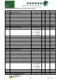
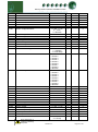
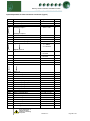
Section Stages ..........................................................................................................................................................57
Alarm Relay ...............................................................................................................................................................57
Stage Sizes ................................................................................................................................................................57
Operation (Fuzzy) .....................................................................................................................................................58
Operation (Staged) ...................................................................................................................................................58
Other operational features .......................................................................................................................................59
Floating Head Pressure ..........................................................................................................................................59
Drop Leg..................................................................................................................................................................59
Night Set-back .........................................................................................................................................................59
Day Set-back ...........................................................................................................................................................59
Invert Relays ...........................................................................................................................................................60
Sticky Fans ..............................................................................................................................................................60
USB Operation ........................................................................................................................................................60
Viewing ......................................................................................................................................................................61
Inputs and Outputs ...................................................................................................................................................61
Input/Output Tables ..................................................................................................................................................61
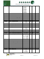
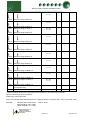
Input/Output table for Pack Controller (Type 1) ......................................................................................................61
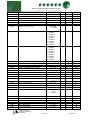
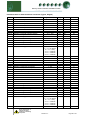
Input/Output table for Dual Pack Controller (Type 2) ..............................................................................................62
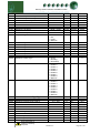
Input/Output table for Pack/Condenser Controller (Type 3) ...................................................................................63
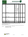
Input/Output table for Dual Condenser Controller (Type 4) ....................................................................................65
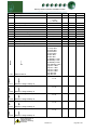
Input/Output table for Condenser Controller (Type 5).............................................................................................67
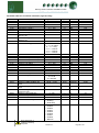
Input/Output table for Pack Controller (Type 6) ......................................................................................................68
Input/Output table for Dual Pack Controller (Type 7) ..............................................................................................69
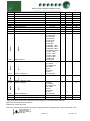
Input/Output table for Pack/Condenser Controller (Type 8) ...................................................................................70
Input/Output table for Dual Condenser Controller (Type 9) ....................................................................................72
Input/Output table for Condenser Controller (Type 10) ..........................................................................................74
Quickview ..................................................................................................................................................................75
Override .....................................................................................................................................................................75
Info Button .................................................................................................................................................................75
Standby Mode ...........................................................................................................................................................75
Probe Offsets ............................................................................................................................................................76
Display Messages .....................................................................................................................................................76
Network Alarms ........................................................................................................................................................76
Specification..............................................................................................................................................................77
Power requirements: ...............................................................................................................................................77
General ....................................................................................................................................................................77
Inputs .......................................................................................................................................................................77
Relay Ratings ..........................................................................................................................................................77
Installation: ................................................................................................................................................................78
Mounting on to a DIN rail ........................................................................................................................................78
Clearances: .............................................................................................................................................................78
Cleaning: .................................................................................................................................................................78
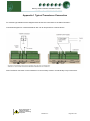
APPENDIX 1 TYPICAL TRANSDUCER CONNECTION ..........................................................................................79
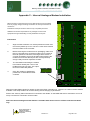
APPENDIX 2 – INTERNAL ANALOGUE MODEM INSTALLATION ........................................................................80
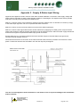
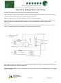
APPENDIX 3 – SUPPLY & STATUS INPUT WIRING...............................................................................................81
APPENDIX 4 – SUPPLY & STATUS INPUT WIRING...............................................................................................82
REVISION HISTORY ..................................................................................................................................................83
Warning
Ensure that all power is
switched off before
installing or maintaining
this product
Please Note
The specifications of the product detailed on this
Set-Up Guide may change without notice. RDM
Revision 2.7
Page 3 of 83