1
Film-Tech
The information contained in this Adobe Acrobat pdf
file is provided at your own risk and good judgment.
These manuals are designed to facilitate the
exchange of information related to cinema
projection and film handling, with no warranties nor
obligations from the authors, for qualified field
service engineers.
If you are not a qualified technician, please make no
adjustments to anything you may read about in these
Adobe manual downloads.
www.film-tech.com
Model CP500
Digital Cinema Sound
Processor
Installation and Alignment
Issue 5
Part No. 91371
Installation and Alignment Manual
For
Model CP500
Digital Cinema Sound Processor
Dolby Laboratories Incorporated
U.S.A. 100 Potrero Avenue, San Francisco, CA 94103
Tel: 415-558-0200; Fax: 415-863-1373, www.dolby.com
U.K. Wootton Bassett, Wiltshire SN4 8QJ
Tel: (44) 1793-842100; Fax: (44) 1793-842101
DISCLAIMER OF WARRANTIES: Equipment manufactured by Dolby Laboratories is warranted against defects in materials and
workmanship for a period of one year from the date of purchase. There are no other express or implied warranties and no warranty of
merchantability or fitness for a particular purpose.
LIMITATION OF LIABILITY: It is understood and agreed that Dolby Laboratories’ liability whether in contract, in tort, under any warranty, in
negligence or otherwise shall not exceed the cost of repair or replacement of the defective components and under no circumstances shall
Dolby Laboratories be liable for incidental, special, direct, indirect or consequential damages (including but not limited to damage to software
or recorded audio or visual material), or loss of use, revenue or profit even if Dolby Laboratories or its agents have been advised, orally or in
writing, of the possibility of such damages.
Dolby and the double-D symbol are registered trademarks of Dolby Laboratories.
Windows 95 is a trademark of Microsoft Corporation
Digital decoding covered by the following U.S. patents: 4,790,016, 4,914,701, 4,799,260 4,941,177, 5,109,417, 5,142,656, 5,230,038,
5,274,740, 5,297,236, 5,357,594, 5,463,424, 5,583,962, 5,608,805, and other worldwide patents granted and pending.
©1998 Dolby Laboratories Inc.
ISSUE 5
Software v 1.30
S98/11507/12003
Dolby Part No. 91371
TABLE OF CONTENTS
SECTION 1 INTRODUCTION
1.1 About the Dolby CP500 ......................................................................1-1
1.2 Hardware Configurations Available....................................................1-1
CP500-D........................................................................................1-1
CP500-300.....................................................................................1-1
CP500-SR......................................................................................1-2
CP500-70.......................................................................................1-2
1.3 About This Manual..............................................................................1-2
1.4 Specifications ......................................................................................1-3
1.5 Regulatory Notices ..............................................................................1-5
FCC ...............................................................................................1-5
UL..................................................................................................1-5
UK .................................................................................................1-5
IEC.................................................................................................1-5
SECTION 2 EQUIPMENT REQUIRED
SECTION 3 INSTALLATION AND JUMPERS
3.1 Replacing an Existing Sound System..................................................3-1
3.1.1 Before playing the film:........................................................3-1
3.1.2 While playing the film:.........................................................3-1
3.1.3 Disconnect the old system ....................................................3-1
3.2 Mount the CP500.................................................................................3-2
3.3 Connect the CP500..............................................................................3-2
3.3.1 Connect Motor Start Relays ................................................3-3
3.3.2 Connect Remote Controls ...................................................3-3
3.3.3 Connection of Solar Cell Boards.........................................3-4
3.4 Check and Set Jumpers........................................................................3-6
Cat. No. 661 Optical Pre-amplifier Card (Analog
Soundtracks) ......................................................................3-6
Cat. No. 681 Analog Switch Card .....................................3-6
Cat. No. 682 Analog Output Card .....................................3-7
Cat. No. 683 Crossover Card (Optional) ...........................3-8
3.5 Install Circuit Cards - Card Descriptions .......................................... 3-10
Model CP500-D .......................................................................... 3-10
Cat. No. 222SR/A Module .............................................. 3-10
Cat. No. 661 Optical Preamplifier Card .......................... 3-10
Cat. No. 681 Input Switch Card ...................................... 3-10
Cat. No. 675A Digital Signal Processing Cards (2) ........ 3-10
Cat. No. 685 6-Channel Analog to Digital Converter
Card ................................................................................. 3-10
Cat. No. 662 6-Channel Digital to Analog Converter
and Voltage Controlled Amplifier Card .......................... 3-10
Cat. No. 682 Analog Output Card ................................... 3-10
Cat. No. 684 System Controller Card.............................. 3-10
Cat. No. 683 Crossover Card (Optional) ......................... 3-11
ii
Dolby Digital Soundtrack Processing System............................. 3-11
Cat. No. 670 Video Front-end Card ............................................ 3-11
Cat. No. 671 DSP Cards (2) ........................................................ 3-11
Cat. No. 673 System Services Card ............................................ 3-11
Cat. No. 675A Digital Signal Processing Card ........................... 3-11
Cat. No. 680 Bit Rate Converter Card ........................................ 3-11
Model CP500-D/300 ............................................................................... 3-11
Model CP500-SR .................................................................................... 3-11
Model CP500-70 ..................................................................................... 3-11
Cat. No. 222A Modules (2)......................................................... 3-11
Cat. No. 669 Adapter Card.......................................................... 3-11
Cat. No. 685 6-Channel Analog to Digital Converter
Card ............................................................................................. 3-11
3.6 Bypass Power Wiring.................................................................................... 3-12
3.7 Power On....................................................................................................... 3-13
3.7.1 Hum and Other Noise Problems..................................................... 3-14
Fold-Out Drawings:
Card Locations
CP500 Wiring
SECTION 4 FRONT PANEL and ALIGNMENT OVERVIEW
4.1 The CP500 Front Panel ................................................................................. 4-1
4.1.1 Soft Keys: SK1 to SK8.................................................................. 4-1
4.1.2 Hard Keys....................................................................................... 4-1
Formats........................................................................................ 4-1
Menu............................................................................................ 4-1
Cancel.......................................................................................... 4-3
OK ............................................................................................... 4-3
Exit .............................................................................................. 4-3
4.1.3 Other Controls and Indicators: ....................................................... 4-3
4.2 System Password........................................................................................... 4-4
4.3 Aligning the B-Chain .................................................................................... 4-5
SECTION 5 B-CHAIN ALIGNMENT
5.1 Check Theater Equipment ............................................................................. 5-1
Amplifiers.................................................................................... 5-1
Air-conditioning .......................................................................... 5-2
5.2 Preparing for Room Equalization.................................................................. 5-2
Using a Microphone Multiplexer with the CP500 ...................... 5-2
5.2.1 Configure the Cat. No. 682 for Use with the Optional
Cat. No. 683 Electronic Crossover Card ................................................. 5-2
5.2.2 Screen Channels ............................................................................. 5-2
5.2.3 Surround Channel Bass Drivers (Optional).................................... 5-3
5.3 Room Equalization........................................................................................ 5-4
5.4 Bypass Crossover Adjustment......................................................................5-15
iii
SECTION 6 A-CHAIN ALIGNMENT
6.1 Aligning the A-Chain .................................................................................... 6-1
6.2 Analog Optical Alignment - Projector........................................................... 6-2
SECTION 7 Cat. No. 700 DIGITAL SOUNDHEAD
7.1 Mechanical Alignment ....................................................................................7-1
7.2 Adjustment Setup with Oscilloscope ..............................................................7-1
7.3 Focus Adjustment............................................................................................7-2
7.4 Exciter Lamp Level Confirmation and Adjustment ........................................7-3
7.5 Film Path Alignment .......................................................................................7-3
7.6 Optical Alignment ...........................................................................................7-4
7.7 How to Identify Types of Soundtracks ............................................................7-6
7.8 Film Threading ................................................................................................7-6
7.9 Cat. No. 673.....................................................................................................7-7
7.10 Projector Changeover / Motor Run Indicators ..............................................7-7
7.11 Format Control ..............................................................................................7-7
7.12 Automatic Selection of the Dolby Digital Format.........................................7-7
7.12.1 A Quick Look at Operation With Standard Set-up........................7-7
7.12.2 Operation with Custom Setup ........................................................7-9
Allowable Source Formats .......................................................... 7-10
Allowable Target Formats ........................................................... 7-10
How It Works .............................................................................. 7-10
Disabling the Auto-Digital Feature ............................................. 7-10
7.12.3 Setting Up the Auto-Digital System............................................. 7-11
Assigning Source Formats........................................................... 7-11
Assigning Target Formats ........................................................... 7-12
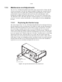
7.13 Maintenance and Adjustments .................................................................... 7-13
7.13.1 Replacing the Exciter Lamp ......................................................... 7-13
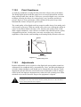
7.13.2 Print Cleanliness........................................................................... 7-13
7.13.3 Adjustments.................................................................................. 7-13
SECTION 8 FINAL ADJUSTMENTS
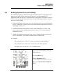
8.1 Setting Optical Surround Delay.......................................................................8-1
8.2 Setting Digital Soundhead Delay ....................................................................8-3
8.2.1 Static.................................................................................................8-3
8.2.2 Dynamic............................................................................................8-4
8.2.3 Typical Settings ................................................................................8-4
8.3 Setting Digital Surround Delay .......................................................................8-5
iv
8.4 Bypass Adjustments ........................................................................................8-6
8.4.1 Before you Adjust ............................................................................8-6
8.4.2 Bypass Level Adjustment (No Cat. No. 683 Electronic
Crossover Card Installed)..........................................................................8-7
8.4.3 Output HF/LF Balance and Level Adjustments(With
Cat. No. 683 Electronic Crossover Card)..................................................8-8
8.4.4 Bypass Level Adjustment for Early Cat. No. 682 (No
Cat. No. 683 Electronic Crossover Card Installed) ........................ 8-10
8.4.5 Early Cat. No. 682 Output HF/LF Balance and Level
Adjustments (With Cat. No. 683 Electronic Crossover
Card)............................................................................................... 8-11
8.5 About Non-sync ............................................................................................ 8-12
8.6 Mute Speed Adjustment ................................................................................ 8-13
SECTION 9 ACCESSORIES
9.1 CP500 Operation with Remote Controls.........................................................9-1
9.1.1 Cat. No. 689 CP500 Remote Control...............................................9-1
9.1.2 Cat. No. 734 CP500 Remote Fader ..................................................9-2
9.1.3 Auditorium Fader .............................................................................9-3
9.2 Operation with Cat. No. 580 Microphone Multiplexer...................................9-4
9.2.1 Operation..........................................................................................9-4
9.2.2 Components......................................................................................9-6
SECTION 10 TROUBLESHOOTING
10.1 During the Show.......................................................................................... 10-1
10.1.1 If Film Sound Is Lost.................................................................... 10-1
10.1.2 If One Channel Fails or is Distorted............................................. 10-2
10.1.3 If Switching to Bypass Does Not Restore Sound ......................... 10-2
10.1.4 If You Hear Extraneous Noises When Playing a
Digital Film ............................................................................................. 10-2
10.1.5 Excessive or Inappropriate Sound From Surround
Speakers .................................................................................................. 10-3
10.1.6 On CP500s Equipped with Cat. No. 683 Electronic
Crossover:................................................................................................ 10-3
10.2 Between Shows ........................................................................................... 10-4
10.2.1 Analog Film Sound Signal Path LEDs......................................... 10-4
10.2.2 Digital Film Sound Signal Path LEDs ......................................... 10-5
10.2.3 Bypass Signal Path LEDs............................................................. 10-7
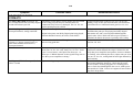
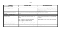
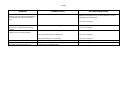
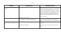
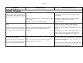
10.3 Troubleshooting Chart................................................................................. 10-7
APPENDIX A ADVANCED OPERATIONS
A.1 Customizing the Format Display Screen........................................................A-1
v
A.2 Saving System Settings...................................................................................A-5
®
A.2.1 Using the Terminal Program in Windows .....................................A-5
Equipment Needed ........................................................................A-5
Transferring Data From the CP500 to the Computer ....................A-5
Transferring Data From the Computer to the CP500 .................. A-9
A.2.2 Using Load500 Software ............................................................... A-11
Equipment Needed ...................................................................... A-11
Transferring Data From the CP500 to the Computer .................. A-11
Transferring Data from the Computer the to the
CP500 .......................................................................................... A-13
A.3 Transferring Data Between Two CP500s ..................................................... A-15
APPENDIX B CAT. NO. 683 ELECTRONIC CROSSOVER
B.1 Description and Features.................................................................................B-1
B.2 Installation ......................................................................................................B-1
B.3 Alignment .......................................................................................................B-2
B.3.1 Screen Channels...............................................................................B-2
B.3.2 Surround Channel Bass Drivers.......................................................B-3
B.3.3 Bypass Crossover Subsystem...........................................................B-3
B.4 Special Applications .......................................................................................B-4
B.4.1 Time Delay.......................................................................................B-4
B.4.2 Crossover Frequency........................................................................B-5
B.5 Headers Available...........................................................................................B-5
B.6 Jumpers and Headers ......................................................................................B-6
APPENDIX C BACKPLANE CONNECTOR ASSIGNMENTS
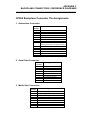
1. Automation Connector: ............................................................C-1
2. Serial Data Connector: .............................................................C-1
3. Motor Start Connector:.............................................................C-1
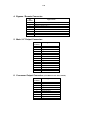
4. Bypass / Remote Connector: ....................................................C-2
5. Main / LF Output Connector: ...................................................C-2
6. Crossover Output Connector: ...................................................C-2
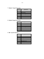
7. Optical 1 Input Connector: .......................................................C-3
8. Optical 2 Input Connector: .......................................................C-3
9. Mic. Input Connector: ..............................................................C-3
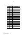
10. Accessory Rack Analog Connector:.......................................C-4
11. Accessory Rack Digital Connector:........................................C-5
12. 6 Channel Input Connector:....................................................C-6
13. Reader 1 and Reader 2 Input Connector:................................C-7
FOLD-OUT DRAWINGS:
System Setup Menu Tree
Alignment and Diagnostics Menu Tree
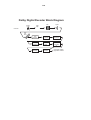
Signal Block Diagram
Backplane Interconnections
vi
APPENDIX D THE DOLBY DIGITAL SUBSYSTEM
D.1 Basic Functions ..............................................................................................D-1
D.2 Discussion of Changeover Technique ............................................................D-3
D.3 Auxiliary Data Channel..................................................................................D-3
APPENDIX E THE EVOLUTION OF DOLBY FILM SOUND
Optical Sound.......................................................................................... E-1
Magnetic Sound....................................................................................... E-2
Dolby Gets Involved................................................................................ E-3
The Next Step: Dolby SR........................................................................ E-4
And Now - Dolby Digital ........................................................................ E-4
About Dolby AC-3 .................................................................................. E-5
Making Films Sound Better .................................................................... E-5
SECTION 1
INTRODUCTION
1.1
About the Dolby CP500
Dolby Laboratories has continuously established new benchmarks for motion
picture sound. The CP500 Digital Cinema Processor maintains that tradition, setting
new standards for performance, value, flexibility, and convenience. Entirely selfcontained, the CP500 provides both Dolby Digital and Dolby analog processing
built in. An easy-to-read LCD screen and uncomplicated front panel soft keys
makes it easy to install, operate, and maintain. Software that can be readily
programmed, controls any existing or future format. Built-in test instrumentation
that includes a real time analyzer make the CP500 easier to align and calibrate than
conventional processors. No external PC is required for setup. Once aligned,
calibration settings can be password protected to prevent mis-adjustment.
Built-in diagnostic software enables theater staff to verify performance of the
complete theater sound system. Calibration settings for a given theater can be
stored on a PC, and should the need ever arise, they can be transferred directly to
another CP500 or other modules, thereby reducing or eliminating the need for
further calibration after repairs. As improvements to the CP500 digital control and
processing software are developed, the latest revisions can be downloaded from a
PC to the CP500 hardware. Moreover, updates to the audio coding used for Dolby
Digital soundtracks, which are included from time to time on Dolby Digital release
prints, download automatically into the CP500 the first time such a print is played in
the cinema.
Options available for the CP500 include internal Linkwitz-Riley crossover networks
(Cat. No. 683) for bi-amplified screen speakers, and 6 channel A/D converter (Cat.
No. 685) for use with Dolby models DA10 or DA20 processors, 70mm magnetic
systems, or other cinema sound systems.
1.2
Hardware Configurations Available
The CP500 is available in four versions:
CP500-D
•
•
Dolby Digital decoding capability
Dolby A-type and SR analog soundtrack decoding capability
CP500-D/300
•
•
•
Primarily used in preview theaters and studios
Dolby A-type and SR analog soundtrack decoding capability
Dolby Digital decoding capability
1-2
CP500-SR
•
•
Dolby A-type and SR analog soundtrack decoding capability
Upgradable to Dolby Digital decoding by means of plug-in circuit cards
CP500-70
•
•
•
Dolby Digital decoding capability
Dolby A-type and SR analog soundtrack decoding capability
70mm magnetic soundtrack capability (includes a 6 channel A/D module
and 4 additional channels of Dolby A-Type noise reduction for use with
an external magnetic pre-amp); can play Formats 42 and 43
Any CP500 configuration also interfaces readily with other film sound equipment.
1.3
About This Manual
This manual is intended to be used by individuals who are qualified in the area of
cinema sound equipment installation and service. The basic day-to-day operation of
the CP500 is covered in the CP500 Users' Manual, Dolby part number 91372.
This installation and alignment manual covers the procedures necessary to ensure
that the theater sound system is accurately aligned to standards that have been
established by Dolby Laboratories. Following these procedures will ensure that the
theater sound system will accurately reproduce the soundtrack as the director and
sound mixers intended.
The Dolby CP500 is the central element of the theater sound system. The projector,
the Dolby Processor, the power amplifiers and the loudspeakers, as well as the
auditorium itself, must all be considered when aligning the system for optimum
performance.
The system alignment procedure is divided into two parts. The B-chain alignment
includes the equalization, loudspeaker crossover, and output level adjustments, in
addition to the regulation of miscellaneous functions, such as fade-out time
adjustment. The A-chain alignment involves adjustments made to the projector
soundhead optics, solar cell, and optical preamplifier card.
1-3
1.4
Specifications
Construction
Rack-mount chassis frame construction with plug-in modules accessible behind hinged front
panel.
Signal Connections
a. Standard 9 pin D-type connectors for Mic., Optical 1, Optical 2, Serial Data, and Motor Start
signals.
b. Standard 25 pin female D-type connectors for Digital Readers 1 and 2, Accessory Unit,
Automation connections, and 6 Channel Analog Inputs.
c. RCA type phono jacks for Non-sync 1 and 2.
d. Phoenix screw terminal connectors for processor outputs, bypass power, and remote control
connections.
Signal Inputs
a. 6 Channel: Six analog inputs for use with external magnetic preamplifier or external
processor, 300 mV operating level. (Requires optional Cat. No. 685.)
b. Optical: Two pairs of balanced inputs for two projectors with stereo solar cells (available from
Dolby Laboratories mounted on brackets for most projector types). Inputs compatible with LED
illuminated reverse-scan analog readers.
c. Non-sync: Two stereo inputs for non-sync sources. 50 kOhm input impedance, 50 mV to 2.5 V
sensitivity. 2:4 decoder may be used to decode Dolby Surround program sources.
d. Microphone: One balanced input for B-chain equalization P.A. mic. or multiplexer and one
unbalanced input for house announcement mic.
e. Dolby Digital Film Reader (CP500-D): Two inputs for connection to penthouse or inboard
readers.
Signal Outputs
47 ohms output impedance will drive any load greater than 600 ohms. Maximum output level, +20
dBu. Typical operating level, -10 dBu.
Operating levels from 25 mV to 0.7 V may be accommodated.
Output For Hearing-impaired System
Center-weighted sum of L, R, C for connection to auxiliary system for the hearing impaired.
Output impedance is 47 ohms with a fixed output level of 200 mV.
Optical Preamplifier
A Cat. No. 661 Optical Preamplifier accepts signals from two projectors with stereo solar cells.
Gain and slit loss adjustments are digitally controlled.
Noise Reduction
Two channels of Dolby A-type noise reduction and two channels of Dolby SR are provided as
standard. Up to six channels of A-type (CP500-70) and two additional channels of studio SR
(CP500-300) can be accommodated.
Four Channel Decoder
Cat. No. 675A DSP Module decodes left, center, right, and surround channels from the two optical
tracks on Dolby analog optical prints. Adjustable delay to optimize front to surround separation.
1-4
Loudspeaker Equalization
L,C,R: 27 band digital 1/3 octave EQ; digitally controlled bass and treble
LsRs: digital 9-band, full octave EQ
SW: Digital parametric EQ with 12dB cut capability
Remote Connections
Connections for up to two Dolby Cat. No. 689 remote fader, format selectors and/or Cat. No. 734
fader-only remotes are provided. A provision is also made for a temporary auditorium fader
consisting of a 100k potentiometer.
Automation
Direct mode allows eight contact closures to ground for selecting formats.
Sequential mode allows a single contact closure to ground for sequencing pre-programmed
formats.
Distortion
Typically 0.05% in Dolby SR mode (Format 05, with output operating level set to -10 dBu and
input 10dB over Dolby level ).
Dynamic Range
Typically 92 dB with fader set to 7.0.
Dimensions
Four units high rack mount chassis. Standard 178 mm high by 493 mm wide faceplate (7 x 9").
Maximum projection behind mounting surface is 360 mm (14.17"). Maximum projection in front
of mounting plate is 32 mm (1.23").
Weight
11.7 kgs (26 lb.) Max.
Power Requirements
100 - 240 VAC, 50-60 Hz Auto Sensing. 2 A max. input current. Single phase. 120 Watts max.
Fuse Requirements
Single 1 1/4" or 5 X 20 mm slow blow fuse according to local safety requirements.
Operating Conditions
0 - 40 oC, 20-80 % humidity, non-condensing.
1-5
1.5
Regulatory Notices
FCC
This equipment has been tested and found to comply with the limits for a Class A digital device,
pursuant to Part 15 of the FCC Rules. These limits are designed to provide reasonable protection
against harmful interference when the equipment is operated in a commercial environment. This
equipment generates, uses, and can radiate radio frequency energy and, if not installed and used in
accordance with this instruction manual, may cause harmful interference to radio
communications. Operation of this equipment in a residential area is likely to cause harmful
interference in which case the user will be required to correct the interference at his or her own
expense.
UL
The CP500 is UL listed. This installation manual is for use by qualified personnel only. To avoid
electric shock do not open the unit or perform any servicing unless you are qualified to do so.
WARNING: Check that the correct fuse has been installed. To reduce the risk of fire, replace the
fuse only with the same type and rating.
FUSE - 2 Amp, time-lag (T2A), 20 mm long, 250 Volt
Dolby part no. 56027
The ground terminal of the power plug is connected directly to the chassis of the unit. For
continued protection against electric shock, a three-pin, correctly wired and earthed power outlet
must be used. Do not use a ground-lifting adapter and never cut the ground pin on the three-prong
plug.
UK
WARNING: THIS APPARATUS MUST BE EARTHED.
As the colours of the cores in the mains lead may not correspond with the coloured markings
identifying the terminals in your plug, proceed as follows:
•
•
•
The core that is coloured green and yellow must be connected to the terminal in
or coloured
the plug that is marked with the letter E or by the earth symbol
green or green and yellow.
The core that is coloured blue must be connected to the terminal that is marked
with the letter N or coloured black.
The core that is coloured brown must be connected to the terminal that is marked
with the letter L or coloured red.
IEC
This unit complies with the EMC requirements of EN50081-1 and EN 50082-1 when installed in
an E2 environment in accordance with this manual.
1-6
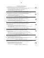
IMPORTANT SAFETY NOTICE
This unit complies with the safety standard IEC65. To ensure safe operation and to guard
against potential shock hazard or risk of fire, the following must be observed:
o If the unit has a voltage selector, ensure that it is set to the correct mains voltage for your supply. If there is no voltage
selector, ensure that your supply is in the correct range for the input requirement of the unit
o Ensure fuses fitted are the correct rating and type as marked on the unit.
o The unit must be earthed by connecting to a correctly wired and earthed power outlet.
o The power cord supplied with this unit must be wired as follows:
Live—Brown
Neutral—Blue
Earth—Green/Yellow
IMPORTANT – NOTE DE SECURITE
Ce materiel est conforme à la norme IEC65. Pour vous assurer d'un fonctionnement sans danger et de prévenir
tout choc électrique ou tout risque d'incendie, veillez à observer les recommandations suivantes.
o Le selecteur de tension doit être placé sur la valeur correspondante à votre alimentation réseau.
o Les fusibles doivent correspondre à la valeur indiquée sur le materiel.
o Le materiel doit être correctement relié à la terre.
o Le cordon secteur livré avec le materiel doit être cablé de la manière suivante:
Phase—Brun
Neutre—Bleu
Terre—Vert/Jaune
WICHTIGER SICHERHEITSHINWEIS
Dieses Gerät entspricht der Sicherheitsnorm IEC65. Für das sichere Funktionieren des Gerätes und zur
Unfallverhütung (elektrischer Schlag, Feuer) sind die folgenden Regeln unbedingt einzuhalten:
o Der Spannungswähler muß auf Ihre Netzspannung eingestellt sein.
o Die Sicherungen müssen in Typ und Stromwert mit den Angaben auf dem Gerät übereinstimmen.
o Die Erdung des Gerätes muß über eine geerdete Steckdose gewährleistet sein.
o Das mitgelieferte Netzkabel muß wie folgt verdrahtet werden:
Phase—braun
Nulleiter—blau
Erde—grün/gelb
NORME DI SICUREZZA – IMPORTANTE
Questa apparecchiatura è stata costruita in accordo alle norme di sicurezza IEC 65. Per una perfetta
sicurezza ed al fine di evitare eventuali rischi di scossa êlettrica o d'incendio vanno osservate le
seguenti misure di sicurezza:
o Assicurarsi che il selettore di cambio tensione sia posizionato sul valore corretto.
o Assicurarsi che la portata ed il tipo di fusibili siano quelli prescritti dalla casa costruttrice.
o L'apparecchiatura deve avere un collegamento di messa a terra ben eseguito; anche la connessione rete deve
avere un collegamento a terra.
o Il cavo di alimentazione a corredo dell'apparecchiatura deve essere collegato come segue:
Filo tensione—Marrone
Neutro—Blu
Massa—Verde/Giallo
AVISO IMPORTANTE DE SEGURIDAD
Esta unidad cumple con la norma de seguridad IEC65. Para asegurarse un funcionamiento
seguro y prevenir cualquier posible peligro de descarga o riesgo de incendio, se han de observar
las siguientes precauciones:
o Asegúrese que el selector de tensión esté ajustado a la tensión correcta para su alimentación.
o Asegúrese que los fusibles colocados son del tipo y valor correctos, tal como se marca en la unidad.
o La unidad debe ser puesta a tierra, conectándola a un conector de red correctamente cableado y puesto a tierra.
o El cable de red suministrado con esta unidad, debe ser cableado como sigue:
Vivo—Marrón
Neutro—Azul
Tierra—Verde/Amarillo
VIKTIGA SÄKERHETSÅTGÄRDER!
Denna enhet uppfyller säkerhetsstandard IEC65. För att garantera säkerheten och gardera mot
eventuell elchock eller brandrisk, måste följande observeras:
o Kontrollera att spänningsväljaren är inställd på korrekt nätspänning.
o Konrollera att säkringarna är av rätt typ och för rätt strömstyrka så som anvisningarna på enheten föreskriver.
o Enheten måste vara jordad genom anslutning till ett korrekt kopplat och jordat el-uttag.
o El-sladden som medföljer denna enhet måste kopplas enligt foljande:
Fas—Brun
Neutral—Blå
Jord—Grön/Gul
BELANGRIJK VEILIGHEIDS-VOORSCHRIFT:
Deze unit voldoet aan de IEC65 veiligheids-standaards. Voor een veilig gebruik en om het gevaar van electrische
schokken en het risico van brand te vermijden, dienen de volgende regels in acht te worden genomen:
o Controleer of de spanningscaroussel op het juiste Voltage staat.
o Gebruik alleen zekeringen van de aangegeven typen en waarden.
o Aansluiting van de unit alleen aan een geaarde wandcontactdoos.
o De netkabel die met de unit wordt geleverd, moet als volgt worden aangesloten:
Fase—Bruin
Nul—Blauw
Aarde—Groen/Geel
GB
F
D
I
E
S
NL
SECTION 2
EQUIPMENT REQUIRED
The following equipment is required for proper installation and alignment of the
CP500 Digital Cinema Processor.
•
Dual-trace oscilloscope with X-Y facilities (minimum bandwidth 20 MHz, 50
MHz recommended).
•
Calibrated microphone (preferably multiple microphones and a multiplexer).
•
Sound pressure level meter with slow time-constant and C weighting scale.
•
Voltmeter for measuring the exciter lamp power supply.
•
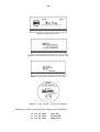
Test Films, available from Dolby Laboratories or equipment dealers (Figures 2-1
through 2-7). We recommend that you make loops of these test films, long
enough to go through the entire projector film path so that azimuth and lateral
film position adjustments can be made accurately.
Figure 2 - 1. Dolby Tone – Cat. No. 69T.
Figure 2 - 2. Pink Noise – Cat. No. 69P.
Figure 2 - 3. 1kHz, Crosstalk/Cell Alignment – Cat. No. 97.
2-2
Figure 2 - 4. SMPTE Buzz Track.
Figure 2 - 5. Stereo Optical Surround Level – Cat. No. 151B.
Figure 2 - 6. Illumination Uniformity – Cat. No. 566.
JIFFY
TEST FILM
Cat. No. 251 SR•D—A subjective film for testing theatre sound
RECORDED IN
Running Time: 6 minutes
Picture format: 1.85:1 widescreen or
2.35:1 anamorphic
Sound formats:
10
05
digital
analog
Dolby Laboratories Inc. • 100 Potrero Avenue
San Francisco, CA 94103-4813
Telephone 415-558-0200 • Facsimile 415-863-1373
Dolby, the Double-D symbol and Dolby Stereo are trademarks
of Dolby Laboratories Licensing Corporation
S96/10117/11146
Figure 2 - 7. “Jiffy” Test Film – Cat. No. 251 SR/Digital.
Additional test films used during Dolby Digital system installation:
•
•
•
Cat. No. 1010
Cat. No. 1011
Cat. No. 1012
Sync Test
Channel ID
Dolby Level
SECTION 3
INSTALLATION AND JUMPERS
Do NOT connect the CP500 to mains power until all connections have been made
and all jumpers have been checked or set.
If air-conditioning noise is audible in the theater, arrange for lubrication of the
motor, fan bearings, adjustment of belts and drives, and cleaning of filters to reduce
the ambient noise to a minimum. If the air-conditioning cannot be repaired switch it
off while the CP500 is being aligned.
3.1
Replacing an Existing Sound System
If the CP500 replaces an existing cinema sound system, play a typical film before
you remove the old system so you will have a benchmark for comparison to the new
system. It can also serve as a check of the positioning of the exciter lamp, the
focusing of the soundtrack lens, and the condition of the solar cell.
3.1.1
Before playing the film:
•
•
•
•
•
•
3.1.2
Verify that the existing power amplifiers are in good working order.
Verify that the existing speakers are in good working order, and that
there is no loose or missing hardware, structural parts, or damaged
drivers in the enclosures.
Verify that all wiring is present and properly connected and that
crossovers are operating and are correctly adjusted.
Check the polarity of the speaker connections.
Verify that there are adequate earth (ground) connections.
Verify that radio interference problems are adequately resolved.
While playing the film:
While you run the film, listen carefully in various parts of the theater for audio
system problems:
•
•
•
•
Hum.
Noise, clicks, pops.
Distorted sound.
Poor tonal balance (lack of high-frequency or bass content).
These problems must be resolved before you can proceed with the new installation.
3.1.3
Disconnect the old system
•
Disconnect power from the existing cinema sound equipment.
•
Disconnect all cabling from the existing sound processor. Leave the
cables connected to the power amplifiers, booth monitor, etc.
3-2
3.2
Mount the CP500
To avoid heat problems, do not mount the Dolby CP500 immediately above or
below the power amplifiers. Locate the power amplifiers away from the CP500 to
avoid hum pickup problems. Always leave a 1U (43 mm, 1.75") space above and
below the CP500 to provide adequate ventilation. Install an air guide or baffle to
deflect hot air from equipment below the CP500.
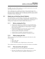
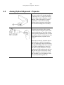
To ensure good ground contact, install star washers on all or at least one rack
mounting screw per piece of equipment (Figure 3-1). This will also aid in the
prevention of electrical noise problems.
Figure 3 - 1. Install star washers to rack mounting screws.
Proper shielding and termination of cables and cable assemblies are also very
important. Be sure to follow the methods shown in the wiring diagrams.
If you are installing a Dolby Cat. No. 700 Digital Soundtrack Reader, refer to its
installation manual for mounting and alignment.
3.3
Connect the CP500
Refer to the appropriate fold-out page (at the end of this section) showing
connections to the various CP500 model configurations.
Make output signal connections by inserting stripped and tinned leads into the
supplied cable connectors and tightening each lead in place by means of the integral
set screw. The cable connectors are then plugged into place at the corresponding
locations shown on the fold-out wiring diagram. Shields must be connected as
shown in the fold out page to avoid radio frequency interference.
NOTE: Follow all local codes and regulations covering electrical wiring. It is recommended that conduit be
used for wiring runs.
Green plastic connector shells have been included in your installation kit for use in countries which are
governed by the EMC directives. The shells must be used as noted on the fold-out pages.
3-3
3.3.1
Connect Motor Start Relays (Models CP500-D, and -70)
For two-projector installations, motor start relays are required for projector
changeover. Digital data on the soundtrack is read in advance of the picture,
therefore an advanced changeover signal is required (see Appendix C). Projector
motor start contact closures provide this signal to the CP500. Isolated contact
closures from mechanical or opto-isolated relays wired across projector motors
must be used. Refer to the Installation Wiring Power and Control diagram at the
end of this section.
Signal levels:
Motor Start
Motor Off:
Less than 1 Vdc with respect to signal ground.
Greater than 3.5Vdc, less than 18Vdc.
Refer to the unit connections fold-out diagram for details (located at the end of this
manual). For single projector installations, a prewire connector is supplied.
3.3.2
Connect Remote Controls
The CP500 is equipped for use with three types of remote controls: the Cat. No.
689, and Cat. No. 734, which are offered by Dolby Laboratories, and an auditorium
fader, which can be made from parts purchased at an any electronics store.
The Cat. No. 689 CP500 Remote Control duplicates the front panel format
selection, fader, and mute controls of the CP500.
The Cat. No. 734 CP500 Remote Fader consists of a shaft encoder with LEDs to
indicate the fader setting.
The auditorium fader is a 100k linear pot wired as a variable resistor, with
minimum resistance corresponding to fader 10.
Details on how to connect any of these remotes to the CP500 are shown in the
Installation Wiring Power and Control drawing located at the end of this section.
3-4
3.3.3
Connection of Solar Cell Boards
In contrast to traditional solar cells, the Cat. No. 655 and other solar cell circuit
boards used by several projector manufacturers are active devices with their own
power supply. Some care needs to be given to the wiring between the board and the
CP500 in order to avoid grounding problems and to provide immunity to RF
interference. In principle, this means separating the audio ground connections and
the RF shielding screen connections.
The 0V point (audio ground) must be connected from the basement reader card to
the CP500 by a separate wire (or wires) along with the audio signal wires. The
cable shield (screen) must be kept separate from the audio ground connections. It
must be connected only to the chassis or enclosure of the equipment at each end.
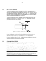
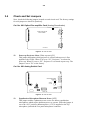
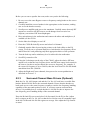
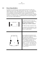
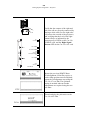
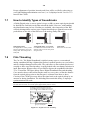
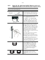
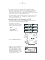
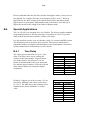
The following diagrams (Figures 3-2 and 3-3) show two connectors on the board.
The three pin connector, J1 is used for the power supply. The signal output
connector J2 provides six output pins; two each for the "balanced" left and right cell
outputs, and two 0V audio ground connections.
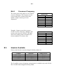
NOTE: The following tables show the Right channel appearing on pins 1, 2, and 3 of the 6-pin connector J2.
The physical orientation of the board mounting in the projector and the orientation of the connector body
mounting on the board affect which channel appears on which pins of the connector. Be aware that pin
allocations for the channels will vary depending on mounting arrangements of the board and
connector. The J2 connector pin solder hole with a square outline is pin 1.
J2 Pin Number
1
2
3
4
5
6
Signal
Right +
Signal Ground
Right –
Left +
Signal Ground
Left –
OR:
J2 Pin Number
1
2
3
4
5
6
Signal
Left Signal Ground
Left +
Right Signal Ground
Right +
There must be a connection between the ground pins at the Cat. No. 655 solar cell
circuit board and the audio common in the CP500. This connection must not use
the shield of the optical input cable, otherwise RF energy can be imposed on the
CP500 ground system.
Pin numbers 6 and 9 of each 9-pin D connector ("Projector") on the CP500 allow
these connections to be made. The wire that connects either of these pins to the
Cat. No. 655 audio ground should pass inside the same shield as the optical input
cables and not connect with the shield at any point.
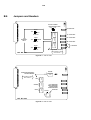
3-5
J2
Cinema Processor
* Ground Wire on J2 Pin 2 is Optional
* Ground Wire on J2 Pin 5 is Required
Chassis Ground
J1
Figure 3 - 2. Wiring using two 3-wire shielded (screened) cables.
J2
Cinema Processor
* Ground Wire on J2 Pin 2 is Optional
* Ground Wire on J2 Pin 5 is Required
Chassis Ground
J1
Figure 3 - 3. Wiring using one 5 or 6-wire shielded (screened) cable.
3-6
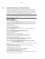
Check and Set Jumpers
Next, check the following jumpers located on each circuit card. The factory settings
for each jumper are shown in [brackets].
Cat. No. 661 Optical Pre-amplifier Card (Analog Soundtracks)
PROJECTOR 2
PROJECTOR 1
J2
POWER-UP PROJECTOR
SELECT JUMPER
DS503
PROJ 1
SIG1
DS501
GND
SIG 2
PROJ 2
CAT.NO. 661
Figure 3 - 4. Cat. No. 661.
J2
Power-up Projector Select (Wake-up state) [P1]
This jumper determines which projector is selected when power is first
applied to the CP500. When J2 is set to “P1”, Projector 1 is selected at
power up. When J2 is set to “P2”, Projector 2 is selected at power up. The
jumper is set to "P1" at the factory.
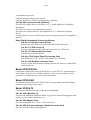
Cat. No. 681 Analog Switch Card
DS100
DS200
RV101
CW
NONSYNC1 L
CW
R135
RV201
NONSYNC1 R
RV100
CW
R235
PHANTOM MIC POWER
FOR EQ MIC
NONSYNC2 L
OFF
ON
CW
RV200
NONSYNC2 R
J3
L1100
C63
J2
C64
3.4
RV1100
CW
EQ MIC
IC9
RV2100
CW
SIG MIC
IC6
IC8
IC7
CAT.NO. 681
Figure 3 - 5. Cat. No. 681.
J3
Equalization Microphone Phantom Power [OFF]
This jumper enables a phantom power source for theater equalization
microphones which require phantom power to operate. When the jumper is
set to the “ON” position, phantom power (15V) is supplied to the EQ
microphone jack and the rear panel microphone connector.
3-7
Cat. No. 682 Analog Output Card
Figure 3 - 6. Cat. No. 682.
Crossover Select Jumpers [NO]
J3
Left Channel
J4
Center Channel
J5
Right Channel
J901 Bypass Audio Channel
These jumpers route the designated signals through an optional Cat. No. 683
crossover card. If the Cat. No. 683 card is installed, these jumpers should be
set to the “YES” position. If the optional Cat. No. 683 is not present, these
jumpers should be set to the “NO” position. The jumpers are set to the “NO”
position at the factory.
NOTE: If bypass audio is routed to the optional Cat. No. 683 crossover card, the bypass portion of the
crossover circuitry must be functioning in order to produce a bypass audio output.
J900
Bypass Calibration
This jumper inserts a calibrated pink noise signal into the bypass system for
level and (optional) crossover adjustments. The calibration signal is enabled
when the jumper is in the “BCAL” position and is disabled otherwise.
NOTE: It is important to move the jumper to the disabled position after calibration is complete so that
the bypass signal path remains completely isolated from any possible erroneous signals in the signal
path.
J902
Bypass Channel Output Level Select [LO]
This jumper, along with the bypass gain adjustment potentiometer (RV901),
adjusts the level of the bypass channel. The jumper provides a “coarse” gain
setting and the potentiometer provides a “fine” gain adjustment. The “HI”
jumper position can be used to produce a higher output level range on the
bypass channel. This jumper is factory set to the “LO” position.
NOTE: If Cat. No. 683 Crossover card is installed, the preferred setting for this jumper is HI.
J2
L and R Surround High-Pass Filter Frequency Select [50Hz]
This header sets filter circuits to the indicated high-pass frequency. Signals
below this frequency are attenuated in order to prevent distortion or damage to
surround speakers that are unable to handle extreme low frequency energy.
NOTE: The function of the Bypass Output Level control changes to Bypass Low Frequency
Balance Control if a Cat No. 683 Crossover Card is installed.
3-8
Cat. No. 683 Crossover Card (Optional)
BYPASS
RN600
CROSSOVER FREQUENCY
SETTING HEADERS
500 Hz
RN202
500 Hz
RIGHT
RN302
500 Hz
LEFT SURROUND
RIGHT SURROUND
BASS SPEAKER
CROSSOVER FREQ
SELECTOR
ACTIVE
100 Hz
50 Hz
RN102
CENTER
RN400
LEFT
500 Hz
Freq setting for large
horn is shown.
CAT. NO. 683
Figure 3 - 7. Cat. No. 683 – Crossover Frequency Setting Headers.
Crossover Frequency Setting Headers- Screen Channels
RN102 Left Channel
RN202 Center Channel
RN302 Right Channel
RN600 Bypass
These headers select the desired crossover frequency. For large horns, the
correct setting is usually 500 Hz. For small horns, 800 Hz is usually
correct. Check the loudspeaker manufacturer’s specifications for details.
Be sure to select the same Bypass crossover frequency header as the
screen channels use. The headers are shipped with each card.
NOTE: Custom settings are possible. See Appendix B, Cat. No. 683.
BYPASS CHANNEL
HIGH FREQUENCY GAIN
HI
LO
BYPASS LEVEL
J600
RN101
LEFT
NO DELAY
1.9 mSEC
DELAY
J100
J200
CENTER
RN201
LOW
FREQUENCY
DELAY
1.9 mSEC
DELAY
RIGHT
NO DELAY
CAT. NO. 683
RN301
DELAY
J300
1.9 mSEC
NO DELAY
L
HF BALANCE
C
HF BALANCE
R
HF BALANCE
LS
RS
LF BALANCE
DELAY SETTING HEADERS
Delay setting for large
horn is shown.
Figure 3 - 8. Cat. No. 683 – Low Frequency Time Delay Enable Jumpers
3-9
Low Frequency Time Delay Enable Jumpers [DELAY]
J100
Left Channel
J200
Center Channel
J300
Right Channel
These jumpers allow the low frequency portion of the designated channels
to be delayed when the jumper is placed in the “DELAY” position. This
compensates for the time offset caused by high frequency drivers being
behind the low frequency drivers in contemporary stage speakers. With the
jumper in the "DELAY" position, sound produced by the low frequency
speakers is delayed to cause the low and high frequency energy to reach
the listener at the same time. There is no low frequency delay when the
jumper is set to “NO DELAY”. The factory setting is “DELAY”.
Low Frequency Time Delay Setting Headers
RN101 Left Channel
RN201 Center Channel
RN301 Right Channel
For large horns, the correct delay setting is usually 1.9 ms. For small
horns, 0.8 ms is usually correct. The headers are shipped with each card.
NOTE: Custom settings are possible. See Appendix B, Cat. No. 683.
RN400 L and R Surround Low-Pass Filter Frequency Select [50Hz]
This header sets filter circuits to the indicated low-pass frequency. Signals
below this frequency are sent to the surround channel low frequency
drivers. Both the Cat. No. 682 Output card and the Cat. No. 683 have
reversible filter headers for the surround channels. Ensure that the headers
on both cards are set to the same frequency, chosen to suit the low
frequency handling capability of the surround speakers in use. If you have
surround bass drivers, it is probably best to set both headers to
100 Hz in order to improve the low frequency power handling ability of
the surround channel. The factory setting is 50Hz.
J600
Bypass Channel HF Output Level Range [LO]
This jumper selects between two gain ranges for the bypass channel high
frequency output. The “HI” setting has approximately 12 dB higher
output level than the “LO” setting. The factory setting is “LO”.
3-10
3.5
Install Circuit Cards - Card Descriptions
If they are not already installed in the CP500 unit, install all of the cards for your
system as shown below for each CP500 version. Note that the noise reduction
modules (Cat. No. 222SR-A) are shipped uninstalled. This is to prevent damage
during shipment due to their weight. Should it ever be necessary to ship the CP500
again, be sure to remove these from the unit and pack them separately.
NOTE: Cat. No. 222SR-A modules are primarily intended for playback of 35mm photographic soundtracks,
and have headroom capabilities based on that medium. As a result, use of Cat. No. 222SR-A modules are not
recommended for playback of 35 mm magnetic print-masters or SR encoded 70mm magnetic film. Contact
Dolby Laboratories for further information.
Model CP500-D
Cat. No. 222SR/A Module
Provides two channels of Dolby A-type noise reduction and Dolby SR processing.
Cat. No. 661 Optical Preamplifier Card *Must be functioning for bypass operation*
Amplifies the outputs of the analog soundtrack solar cells in the selected projector.
Projector select logic.
Provides slit loss equalization.
Cat. No. 681 Input Switch Card
Stereo analog multiplexer for selecting signal to be fed to noise reduction cards.
Audio sample rate clock.
Cat. No. 675A Digital Signal Processing Cards (2)
Matrix decoder for Dolby Pro-Logic.
Non-sync processing.
Signal generation and signal analysis functions.
Twenty-seven band 1/3 octave equalization for L, C, R channels.
Nine band octave equalization for L and R surround channels.
Equalization for subwoofer channel.
Cat. No. 685 6-Channel Analog to Digital Converter Card
Used for external 6-channel analog inputs (optional).
Cat. No. 662 6-Channel Digital to Analog Converter and Voltage
Controlled Amplifier Card
Converts digital data to analog audio and includes the main fader voltage controlled
amplifier.
Cat. No. 682 Analog Output Card *Must be functioning for bypass operation*
Switches and routes output channels.
Contains treble and bass control circuits.
Generates hearing impaired output and mid-surround output.
Contains bypass power regulator and output amplifier.
Cat. No. 684 System Controller Card
Must be present for level control in bypass mode. Bypass will function at a fixed
level if this card is not present or operational.
3-11
Contains Microprocessor.
Controls front panel display and controls.
Contains interface for remotes and automation equipment.
Cat. No. 683 Crossover Card (Optional)
Provides active high- and low-pass filters on L, C, and R signals for bi-amplified
installations.
Provides low frequency surround channel outputs.
Provides low frequency delay for time alignment of L, C, and R low frequency
drivers.
Contains bypass crossover and must be present for bypass operation in bi-amplified
systems.
Dolby Digital Soundtrack Processing System
Cat. No. 670 Video Front-end Card
Digitizes the video data received from the film soundtrack reader.
Cat. No. 671 DSP Cards (2)
Processes the digitized video data and extracts the AC-3 bitstream.
Cat. No. 673 System Services Card
Contains the operating software.
Cat. No. 675A Digital Signal Processing Card
This additional Cat. No. 675A provides Dolby AC3 decoding.
Cat. No. 680 Bit Rate Converter Card
Converts PCM audio from the variable projector rate clock to a stable PCM
audio sample rate.
Model CP500-D/300
Contains the same boards as the CP500-D above, except Cat. No. 300 modules are
used in place of the Cat. No. 222SR/A modules. A Cat. No. 668 Adapter Card is
required. Used primarily in preview theaters and studios.
Model CP500-SR
Contains the same boards as the CP500-D above except without the Dolby Digital
soundtrack processing system cards.
Model CP500-70
Contains the same boards as the CP500-D, and additionally:
Cat. No. 222A Modules (2)
Provides four additional channels of Dolby A-type noise reduction bringing the total
number of noise reduced channels to six.
Cat. No. 669 Adapter Card
Used for installing the two Cat. No. 222A cards above.
Cat. No. 685 6-Channel Analog to Digital Converter Card
Used for external 6-channel analog inputs.
3-12
3.6
Bypass Power Wiring
For emergency operation, the CP500 comes equipped with an independent external
mains power module. If the main power supply or processor circuitry fails, the unit
will automatically switch to bypass operation, allowing the show to continue with
limited sound processing functions. The unit can also be switched manually to
bypass operation by pushing a button located inside the front panel and labeled
POWER/BYPASS.
In some countries the primary cable for the module may not have a mains plug
fitted. These unterminated leads must be as follows:
Brown wire -- Live or hot
Blue wire -- Neutral
NOTE: If you are uncertain about the wiring of your mains outlet do not use it. Consult a qualified
electrician.
For safety reasons, the bypass power module contains an internal fuse. DO NOT connect the module to AC
mains power until the output wires have been connected to the CP500. Otherwise, shorted secondary wires
will blow the fuse.
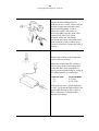
Install the ferrite clamp on the bypass power supply cable where it connects to the
back of the CP500. Open the clip and wrap the bypass power supply wire around
one side of the ferrite three times so that the loops lie inside the ferrite channel.
Close the clip until it snaps firmly closed. Make sure that the bypass power supply
cable is not pinched between the halves of the ferrite clamp.
3-13
3.7
Power On
Connect the bypass power module to the CP500 and plug it into AC mains. The
unit is shipped with the POWER/BYPASS switch set to BYPASS. The front panel
BYPASS LED should light.
Open the front panel and confirm that one of the Projector Select LEDs is on.
Projector 1 or Projector 2 is selected by Jumper J2 on the Cat. No. 661 (See
manual section 3.4).
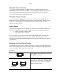
Connect the main power cable. Then, push the Bypass/Power button to turn on the
CP500.
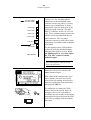
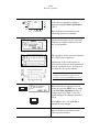
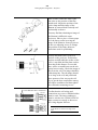
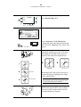
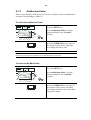
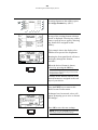
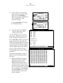
When power is first applied, the first
screen that appears displays the revision
level of the software. Next, a brief
"Loading System" message is displayed.
In a few seconds, the Current Format
screen appears. This is the normal screen
that the projectionist or any other
operator would see and the only screen
they will need to see for ordinary
purposes.
Run quick checks to confirm that:
• Rotating the front panel knob changes the numbers displayed next to it.
• Pushing the MUTE button causes the MUTE LED to flash.
• Pushing any of the buttons on each side of the display causes the mute LED to
go off and the LED next to the button pushed to go on (except buttons next to
" " on the display).
3-14
3.7.1
Hum and Other Noise Problems
If you hear undesirable hum from the speakers when you apply power to the CP500
and other projection room equipment, check the following list for possible causes.
1.
Equipment grounding. All equipment including the CP500 is grounded to
the rack. To ensure good ground contact, install a starwasher to one
mounting screw per piece of equipment. Installation of star washers is
strongly recommended because electrical contact may not be achieved since
modern powder coat paints can be very tough.
2.
Ground loops caused by audio signal wiring, especially to power amplifiers.
Be sure to check the booth monitor installation.
3.
Projector power wiring. All mains wiring should be properly grounded.
4.
Room lighting dimmer controls (SCR-TYPE).
5.
Power amplifiers. Disconnect from the CP500 and ground the inputs to
determine if the power amplifiers are causing hum problems.
6.
Solar cell wiring. (Analog film sound format selected). Check the shield
connections. Cell wiring should be placed away from mains and other
wiring. Cell wires must not be connected to the frame of the projector.
7.
Exciter lamp power supply. Check for ripple on the DC power supply
outputs. Some old exciter lamp power supplies and emergency supplies
provide AC to the lamp. The resulting hum makes them totally unsuitable
for a Dolby film sound system. Such exciter supplies must be replaced.
8.
Projection room lighting/solar cells. Ambient lighting, especially
florescent tubes, can leak into the solar cell area and cause hum.
SECTION 4
FRONT PANEL AND ALIGNMENT OVERVIEW
This section describes the CP500 LCD display and operation of the front panel
controls, along with of an overview of the general principles involved in the
alignment of Dolby cinema equipment. It is useful to develop an understanding of
why the CP500 is aligned as described in this manual. If the installer is already
familiar with the CP500 and these principles, or is in a hurry to complete the
installation, this section may be read later. Continue the installation procedure
beginning with Section 5.
4.1
The CP500 Front Panel
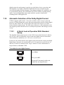
4.1.2
Soft Keys: SK1 to SK8
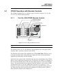
(SK1)
(SK5)
(SK2)
(SK6)
(SK3)
(SK7)
(SK4)
(SK8)
The buttons located on each side of the LCD display are sometimes called "soft
keys"(SK). That is, they do not have a single fixed function but rather their function
is software controlled and changes based on the current screen displayed. The
purpose of each button is shown on the display and can change with each different
displayed screen.
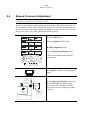
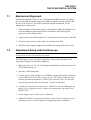
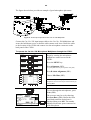
4.1.3
Hard Keys
FORMATS
The single large and four small keys along the bottom of the display are the "hard
keys". Their function is labeled on the panel. The large key on the left,
FORMATS, is used to return to the Format Selection (Current Formats) screen
from any other menu screen. This screen is displayed during normal day-to-day
operation of the CP500. If any other screen or menu is displayed, this button returns
the display immediately to this "top" of the menu tree.
MENU
The MENU key is used as the first step in selecting all software functions and
menus except format selection. It selects or returns the unit to the top menu.
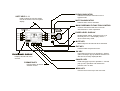
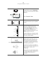
BYPASS INDICATOR
Indicates continuous red when unit is in
bypass mode.
SOFT KEYS 1 - 8
Used to select the function shown
next to the switch in the front panel
display.
MUTE ON INDICATOR
Flashes when mute is activated.
MAIN FADER/MULTI-FUNCTION CONTROL
Controls sound level and also is used for
data selection in menu operations.
(SK1)
(SK5)
(SK2)
(SK6)
(SK7)
(SK4)
(SK8)
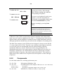
Displays fader setting. Ranges from 0 to 10.
Normally set to 7.0 This display shows '- -'
when in data entry mode.
MUTE KEY
Mutes output to all channels when activated.
EXIT KEY
Used to select the previous menu.
OK KEY
FRONT PANEL DISPLAY
Displays format and menu
screens.
FORMATS KEY
Used to switch to format
selection screen.
Used during pop-up menu operations. Selects
option currently in pop-up window selection box.
Also stores currently displayed data.
CANCEL KEY
Used during pop-up menu operations. Cancels
pop-up menu operation and restores the
previous menu or data.
MENU KEY
Used to return to the top of the menu tree.
4-2
(SK3)
FADER LEVEL DISPLAY
4-3
CANCEL
Many of the screens used during set-up, alignment, or diagnostics contain a "PopUp" screen within the main screen. The CANCEL key is used to cancel the current
pop-up operation being performed and restore any data that was changed during the
pop-up screen operation.
OK
This key is used to accept and store the current setting in a pop-up screen.
EXIT
This key is used to signal completion of an adjustment procedure or select the
previous screen.
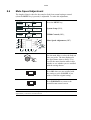
4.1.3
Other Controls and Indicators
To the right of the display is another window showing the selected fader level. As
with previous generations of Dolby cinema processors, a fader setting of "7.0" is the
nominal correct operating level. This setting matches the level used during the film's
production. As the main fader (or front panel knob) is turned, the numbers on the
display will move from zero to ten. The main fader rotates continuously with no
end stops. The number displayed will always indicate the current level setting.
Bypass
Mute On
The MUTE button is used to fade the sound down without disturbing the current
fader setting. A green LED, MUTE ON, located above the fader level display will
flash, indicating that the CP500 outputs are muted.
A BYPASS LED is located to the left of the MUTE ON LED. As with other
Dolby cinema processors, the CP500 utilizes a separate back-up power supply
which is used during emergency operation. If the CP500 is operating in bypass
mode, this red LED will come on (not flashing). If there should be a failure, the
system can switch into bypass mode either temporarily or permanently. The
minimum electronics required for a bypass output signal from the CP500 is:
•
•
•
•
Functioning bypass power transformer (external module)
Cat. No. 661 Optical Preamplifier card
Cat. No. 682 Analog Output card
Cat. No. 683 (optional) Crossover card, if used in a bi-amplified
installation.
4-4
A manual bypass push-button is located inside the front panel on the right hand side
of the unit.
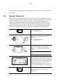
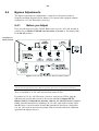
4.2
System Password
Many of the CP500 alignment functions can be protected from unauthorized access
be using a system password (any four numbers). A password can be stored after the
system is aligned in order to block any changes to the B-chain alignment, level
settings, or time delays. Knowledge of this password would be required to enter
these CP500 menus. The CP500 is shipped with no system password. The number
stored in CP500 memory is "0000". This allows access to all alignment functions.
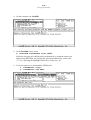
The following procedure should be used to set or change the system password.
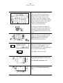
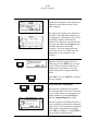
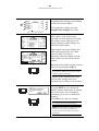
Press the MENU key.
MENU
The Menu Selections screen will be
displayed.
Press Alignment (SK2).
FORMATS
Menu
Cancel
OK
Exit
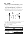
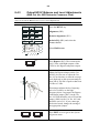
The System Alignment screen will
appear. Press Set System Password
(SK8).
FORMATS
Menu
Cancel
OK
Exit
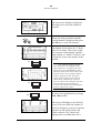
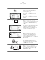
NOTE: If a system password has already been
stored in memory, then the screen below will
appear.
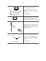
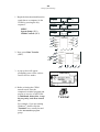
Rotate the front panel knob to select the
digit you wish to set, then press and hold
soft-key SK4, "1234", while rotating the
front panel knob to set the desired
number. Repeat this process for any of
the four password digits you wish to set.
OK
Press the OK key to store the new
password.
4-5
4.3
Aligning the B-Chain
The B-chain is defined as those system components from the fader through the
loudspeakers. In the CP500, available adjustments include equalization, level
control, and digital soundhead, analog, and digital surround delay settings.
Adjustable mute fade-out time is also provided.
It is not practical for the entire cinema industry to standardize on a single make and
model of loudspeaker. In any event, the different acoustical characteristics of
individual theaters would, to some extent, negate any such standardized speakers.
Electronic equalization of each loudspeaker system achieves consistent results in a
broad spectrum of environments, and with a broad range of speakers. Accurate
equalization requires the use of standardized acoustic measurement procedures.
A pink noise generator provides a continuous random noise signal that covers the
total bandwidth and is used to measure and adjust the response of the loudspeakers.
The use of random noise eliminates the problems inherent with tones (standing
wave patterns in the theaters) and enables the frequency response of the entire
system to be observed. Each channel can be measured and adjusted independently
of the other channels.
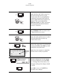
A calibrated microphone or a multi-microphone setup with multiplexer is placed in
the auditorium to receive the pink noise reproduced by the loudspeaker. The output
of the selected microphone is fed to a real time analyzer (RTA) circuit built into the
CP500 cinema processor, and equalization can be performed using the CP500 front
panel display to show the audio spectrum received by the microphone(s). Pure pink
noise would yield a “flat” horizontal line on the RTA. Thus, the effect of
adjustments to the equalizers is quickly and easily seen.
One of the problems inherent in equalization is the nature of the environment. In an
open space, a perfect loudspeaker, radiating a perfectly flat response in all
directions, placed in front of a perfectly flat microphone, producing perfectly flat
response to sounds arriving from all directions, will display a perfectly flat response
on the RTA from pink noise. In an enclosed space such as a theater, the results are
different. When the pink noise generator is first turned on, all of the sound that
initially reaches the microphone comes directly from the loudspeaker; the response
is flat—for a few milliseconds. Then reflected sound from the walls, ceiling, floor,
seats, etc. starts to arrive at the microphone together with the direct sound from the
loudspeaker. This indirect or reflected sound reinforces the direct sound. The
system soon settles into an equilibrium condition. As much energy is being absorbed
at the walls, ceiling, etc. as is fed into the room. Since high and mid frequency
energy is absorbed when sound is reflected, the displayed response appears to have
a rising bass and a falling treble characteristic. At first glance, rolling off the bass
and boosting the high frequencies may appear to be the logical approach for a flat
steady-state response, but such an arrangement works only on sustained sounds.
Dialogue contains short, impulsive sounds and will yield a much-too-bright result
4-6
because there is no time for reverberation to build and add to the original sound.
What is required is a curve that favors such impulsive “first arrival” sound and
implies the same gently falling response that is observed when the output of an ideal
loudspeaker is measured with a perfect microphone in the theater.
The amount of reverberation varies with frequency and the higher the frequency the
more the treble will be absorbed rather than being reflected. A typical reverberation
curve in a theater rolls off at about 3 dB per octave above 2 kHz. This characteristic
is used to define the standard steady-state response curve for all dubbing theaters in
which films with Dolby soundtracks are mixed and for all Dolby processor-equipped
cinemas.
The size of the theater affects the reverberation time and, therefore, the
measurement of frequency response. After alignment to this standard curve, some
slight adjustment of high frequency slope may be found necessary for extremely
large or small theaters. The Treble Control can be used to reduce the output on the
response curve by approximately 1 dB at 8 kHz for very large theaters; an increase
of 1 dB at 8 kHz may be in order for a very small theater. Any such adjustment
should be based on an evaluation by ear of actual known films rather than as a rule
of thumb.
Some loudspeakers used in theaters are far from ideal and require boosting of the
low- and high-frequency extremes in order to produce an approximation of the
standard reference response curve. Bass and treble controls–centered on the
turnover points of typical loudspeakers–lift the ends of the spectrum without the
need for large amounts of narrow-band boost from the third-octave EQ circuitry.
The final factor is masking of the screen. Most films today are shown in a widescreen format. The masking curtains of the screen must be drawn back sufficiently
to clear the left and right speakers before any adjustments or measurements are
made. The treble horns should clear the screen frame and be mounted as close as
possible to the screen. Conventional black felt side masking can severely curtail high
frequency response. Consequently, there would be severe losses if the left and right
loudspeakers were equalized with the masking open as for a 2.35:1 film, and then
the masking were brought in for a 1.85:1 film, thus obscuring the outer speakers.
To avoid this problem, some theaters have installed acoustically transparent
masking cloth, and others leave the masking open whenever they are showing a
1.85:1 film with a stereo soundtrack. Moving the speakers towards the center of the
screen so as to clear heavy masking is not a good solution, since the stereo
separation would be degraded.
Repainted screens cannot be used for quality sound playback, since the perforations
which allow the high frequencies through the screen can become clogged with
paint.
SECTION 5
B-CHAIN ALIGNMENT
5.1
Check Theater Equipment
Thoroughly check the loudspeakers and power amplifiers for sources of poor
performance:
•
Check that the loudspeaker cables are in good condition and that they of a
suitable gauge for the impedance of the speakers and the length of the run.
•
Rattles (a leak in the low frequency driver cabinet may appear to be a rattle).
•
Loose bolts or other hardware.
•
Open drivers.
In systems with pairs of drivers – low frequency or high frequency – one
voice coil of the pair may be open but the system will still function.
Check the speakers with an ohmmeter. If one channel requires markedly
more equalization than the other or if one speaker overloads at lower
levels than the other speakers, an open driver circuit could be the cause.
•
Missing drivers or other components.
•
The settings of the crossovers to match the type of drivers in use and the
acoustics of the theater.
The high frequency driver level control must be set for the best possible
frequency response before you attempt any equalization. This is also true if
the system uses active crossovers with bi-amp equipment.
•
Phasing between the low frequency and high frequency drivers, and between the
channels.
•
Aiming of speakers.
Check that the speakers are correctly aimed into the auditorium, and that
they are not obstructed by the screen frame, struts or other obstructions.
•
Check that speakers are correctly connected; that the speaker on the left is
connected to the left power amplifier.
Amplifiers
•
Distortion.
•
Gross gain differences among amplifiers.
If one amplifier differs in performance from the others, it should be checked
and repaired, if necessary, before proceeding further. Input gain controls
should all be at the same setting.
5-2
B-Chain Alignment
•
•
Blown fuses.
Good air movement through power amplifiers.
Air-conditioning
If air-conditioning noise is audible in the theater, arrange for lubrication of the
motor and fan bearings, adjustment of belts and drives, and cleaning of filters to
reduce the ambient noise to a minimum.
5.2
Preparing for Room Equalization
Using a Microphone Multiplexer with the CP500
If you are using a Dolby Cat. No. 580 Microphone Multiplexer system and need
instructions on its use, turn to Section 9.2.
5.2.1
Configure the Cat. No. 682 for use with the
Optional Cat. No. 683 Electronic Crossover Card
Verify that the Cat. No. 682 jumpers J901, J3, J4, and J5 are set to the "YES"
position to enable the crossover features of the Cat. No. 683.
5.2.2
Screen Channels
The factory setting for the Cat. No. 683 card has the Low Frequency Time Delay
Enable Jumpers set to DELAY. This indicates that jumpers J100, J200, and J300 of
the Cat. No. 683 card allow the low frequency portion of the designated channels to
be delayed by 1.9 ms or 0.8 ms. The “DELAY” setting compensates for the time
offset caused by high frequency drivers being behind the low frequency drivers in
contemporary stage speakers. Sound produced by the low frequency speakers is
delayed to cause the low and high frequency energy to reach the listener at the same
time. There is no low frequency delay when the jumper is set to “NO DELAY”.
Board locations RN102, RN202, RN302, and RN600 select the desired crossover
frequency and locations RN101, RN201, and RN301 select the time delay. For
large horns, the correct setting is usually 500 Hz and 1.9 ms. For small horns, 800
Hz and 0.8 ms is usually correct. Check the loudspeaker manufacturer’s
specifications for details.
5-3
B-Chain Alignment
Before you set out to equalize the room, make sure you do the following:
1. Be sure to use the same Bypass crossover frequency setting header as the screen
channels use.
2. Carefully install the correct headers in the appropriate socket locations, making
sure to set the header correctly.
3. Set all power amplifier gain pots to the maximum. Carefully ensure that only HF
outputs are routed to the HF horns to avoid damage from excessive low
frequency excursion of HF horn diaphragms.
4. Place microphones in the auditorium and connect the mikes and multiplexer (if
available) to the CP500.
5. Set the fader level display to read “0”.
6. Enter the CP500 B-chain EQ screen and select Left channel.
7. Gradually turn the fader by moving the pointer to the fader slider on the EQ
screen. Verify by ear or spectrum analyzer or both that the low frequency driver
and HF horn are each producing only their appropriate halves of the spectrum.
8. Turn the fader up until a satisfactory level is achieved in the auditorium.
9. Set all EQ controls to flat.
10. Using the Left trimpot on the edge of the CN683, adjust the relative HF horn
output level so that the low frequency driver and HF horn output levels match in
the octaves just above and just below the crossover frequency. For example, if
the crossover frequency is set to 500 Hz, then the level from 250-500 Hz should
match that from 500-1,000 Hz.
11. Adjust the Right and Center channels, then proceed to room equalization as
described in Section 5.3.
5.2.3
Surround Channel Bass Drivers (Optional)
Both the Cat. No. 682 Output card and the Cat. No. 683 card have reversible filter
headers labeled 50/100 Hz for the surround channels. Ensure that the headers on
both cards are set to the same frequency (usually to suit the low frequency handling
capability of the surround speakers in use). If you have separate surround bass
drivers, it is probably best to set both headers to 100 Hz in order to improve the
low frequency power handling ability of the surround channel.
Enter the B-chain EQ screen and select Left Surround. Set the EQ to flat. Adjust
the Ls trimpot on the Cat. No. 683 so that the level in the room is reasonably equal
in the 40-100 Hz and 100-200 Hz regions on average. Now adjust the EQ controls
as usual.
5-4
B-Chain Alignment
5.3
Room Equalization
Equalization is performed using a real-time analyzer built into the CP500. The
adjustment for the five full range channels involves two steps - coarse adjustment
and fine adjustment, using a 27-band equalizer for each of the screen channels (left,
center, and right), and a 9-band equalizer for the two surround channels (left
surround and right surround). Subwoofer channel equalization involves setting the
frequency, "Q", and level of "cut". The real-time analyzer screen displays a standard
response curve. The ideal setting is reached when the room response readings fall
on or very close to this standard curve.
POWER AMPS
OFF
Set all the gain controls on all power
amplifiers to a known repeatable setting.
The preferred setting for most
amplifier gain controls is maximum.
If a different setting is required in order
to optimize the noise performance of the
system, the controls should be locked in
position or marked clearly.
Position calibrated microphones in the
theater. Whenever possible, use multiple
microphones and a multiplexer.
(Suggested microphone positions for use
with a multiplexer are shown in Section
9.2.) For a single microphone, the
recommended position is shown in the
diagram – 2/3 of the way from the front
speakers to the rear – but off the axis of
the center speaker – 5 feet off the floor
level – and angled 45 degrees upward
toward the screen.
5-5
B-Chain Alignment
WARNING: The following steps will cause the CP500 to output pink noise to the power
amplifiers. The CP500 is shipped with the output levels set to a minimum. If you are unsure of the
settings on your unit, turn off the power amplifiers before pressing the Output Adjust key. Then,
press the key and observe the front panel display; it will show the present output level adjustment
settings. With the settings at minimum, excessive loudness will usually not be a problem.
To perform a preliminary adjustment
of the output level:
press:
screen shows:
Menu
Format
Selection
key
press:
screen shows:
Menu
Selection
Allignment
Press the MENU key,
key
press:
screen shows:
Press Alignment (SK2),
utput A ust
System
Alignment
key
(A system password may be required at this point.)
Choose Output Adjust (SK2).
F
MA S
Menu
it
ancel
DS100
DS200
RV101
CW
Phantom power is optionally provided to
both connectors via a jumper on the Cat.
No. 681.
NONSYNC1 L
PHANTOM MIC POWER
FOR EQ MIC
CW
R135
RV201
NONSYNC1 R
CW
R235
RV100
NONSYNC2 L
OFF
ON
CW
RV200
NONSYNC2 R
L1100
J3
J2
RV1100
CW
EQ MIC
RV2100
CW
SIG MIC
IC6
CAT. NO. 681
The spectrum analyzer, built into the
CP500, has automatic level control covering a range of input levels. However, if
you get an error message that reads that
the input level is too low or too high, the
EQ mic trimpot on the Cat. No. 681
should be adjusted to have the level meter
on the Cat. No. 222 show approximately
Dolby level for 85 dBC pink noise in the
auditorium. This will place the signal in
the middle of the analyzer’s acceptable
level range.
5-6
B-Chain Alignment
LEFT SIGNAL PRESENT
RIGHT SIGNAL PRESENT
NONSYNC1 LEFT
NONSYNC1 RIGHT
NONSYNC2 LEFT
NONSYNC2 RIGHT
EQ MIC INPUT
EQ MIC
SIGNATURE MIC
CAT. NO. 681
Connect Cat. No. 580 Microphone
Multiplexer to the microphone input
connector on the rear panel, or if using
another type of multiplexer or single
microphone, open the front door of the
CP500 and plug it into the "EQ MIC
INPUT" connector on the Cat. No. 681
card. This is a balanced input connection
which is wired in parallel with the rear
panel connector. The rear panel
connector can also be used with a single
microphone if a suitable cable or adaptor
is provided.
The left signal presence LED indicator
on the top card edge should illuminate
indicating that signal is present. If it is
not illuminated or is very dim, adjust
the "EQ Mic" control to obtain
sufficient signal.
NOTE: If your microphone requires phantom
power, move jumper J3 on the Cat. No. 681
board to the ON position.
Pink noise will now be routed to the
center channel output.
The calibration is retained in CP500
memory and can be used in future adjustments, however it is advisable to
recalibrate the system when re-arranging
microphones because the sound pressure
level will vary slightly with microphone
placement.
30
40
70
50
FF
O
80
60
With a hand-held sound pressure level
meter, measure the noise level in the
room. Enter this reading in the box displayed by rotating the front panel knob,
then press the OK key.
OK
If the sound pressure level in the theater
is too low, a dialog box will appear on
the CP500 screen.
30
40
70
50
FF
O
80
60
5-7
B-Chain Alignment
Adjust the level in the room to about 85
dBC, using the EQ mic control as
mentioned above. Verify the level by
using your hand-held sound level meter.
“85 dBC”
SIGNAL PRESENT
SIGNAL PRESENT
Now open the front door of the CP500
and locate RV1100, the second trimpot
from the bottom on the Cat. No. 681.
NONSYNC1 LEFT
NONSYNC1 RIGHT
NONSYNC2 LEFT
EQ MIC INPUT
RV1100 EQ MIC
A
SIGNATURE MIC
Cat.No.222SR/A
Cat.No.222SR/A
NONSYNC2 RIGHT
Dual SR/A Decoder Module
SR
SR
CAT. NO. 681
Adjust the trimpot so that the 4-LED
Dolby level meter on the Cat. No. 222
(standard or -300 versions) or righthand Cat. No. 222 (70 mm versions)
indicates approximately equal greens.
CAT. NO. 222
NOTE: Some CP500-300 versions may not have a
Cat. No. 222 installed. On these units, adjust the
trimpot so that the signal-present LED at the top of
the Cat. No. 681 flickers and is reasonably close to
full brightness. Its action should be similar to that of
the selected channel’s signal-present LED on the
Cat. No. 682.
If the CP500 has previously been
calibrated, it will display a dialog box
asking if calibration is to be performed or
if the old calibration data is to be used.
Press OK to recalibrate, or CANCEL to
use the old calibration data.
NOTE: While in the output level adjust menu,
pressing the Calibrate SPL key (SK1) will allow
recalibration of the system.
5-8
B-Chain Alignment
Each of the channels should now be
adjusted to give a reasonable sound
pressure level in the room. It is not
necessary to get exact readings at this
point since the levels will change slightly
during equalization of the room. Exact
output level adjustment must be
performed after equalization.
To select the channel to be adjusted,
rotate the front panel knob. Pink noise is
routed to the channel indicated by the
video highlight along the bottom of the
screen.
FORMATS
Menu
Cancel
OK
Adjust the output level of the selected
channel by pressing and holding the
Up/Down Arrow key (SK4) and
rotating the front panel knob.
Exit
When all the channel output levels are
adjusted, press the EXIT key. The
system will display a box prompting you
to save or discard the changes.
EXIT
Press OK to save the settings.
OK
To perform equalization of the room,
Press B-Chain Alignment (SK1).
FORMATS
Menu
Cancel
OK
Exit
Then, press B-Chain Equalization
(SK1).
FORMATS
Menu
Cancel
OK
Exit
5-9
B-Chain Alignment
The system now displays a dialog box
allowing you to select the channel to
equalize.
OK
Rotate the front panel knob until the
desired channel is displayed, then press
the OK key to select the channel.
The display will switch to the 27 Band
Half-Screen mode. This screen is split
into two parts which display equalizer
band settings, or “sliders” at the top, and
a frequency versus level analyzer at the
bottom.
SK1
SK1
SK3
NOTE: For enhanced resolution, the RealTime Analyzer has a second display mode,
called "Full-Screen". To change to full screen
display mode, press the Full Scrn key (SK1).
This larger display allows closer scrutiny of the
analyzer's results. Only one graphic equalizer
control is displayed at a time. Once again,
rotating the front panel knob will select the
band to adjust, and holding the "Up/Down
arrow" key (SK4) while rotating the front panel
knob will adjust the selected band's EQ.
To return to the "Half Screen" mode of display,
press the “Split Scrn” key (SK1).
Set the coarse equalization by pressing
Treb / Bass (SK3).
The screen will change to the Bulk EQ
screen. The lower half will continue to
show the frequency versus level analyzer
and the top will switch to Bass and
Treble controls. (The "full-screen"
display mode is available here also.)
5-10
B-Chain Alignment
Adjust the Bass and Treble controls to
move the room levels close to the
reference line. This is accomplished by
rotating the front panel knob until the
arrow is under the desired control to be
adjusted. Then, press and hold the
Up/Down arrow key (SK4), and rotate
the front panel knob until the desired
response is displayed.
SK4
Press All Bands (SK3) to return to the
27 Band Half-Screen screen.
SK3
Rotate the knob until the arrow is under
the desired band shown in the top
section of the screen.
Perform fine adjustment of each band by
pressing and holding the SK4 key while
rotating the front panel knob.
SK4
Reference
Response
Line
Adjust the room response to match the
reference line as closely as possible.
When the adjustments for this channel
have been completed, press the EXIT
key. If changes have been made, a box
will appear asking if the changes should
be saved.
EXIT
Press OK to save, or CANCEL to
discard the new changes.
OK
5-11
B-Chain Alignment
Select the next channel to adjust by
again pressing B-Chain Equalization
(SK1).
FORMATS
Menu
Cancel
OK
Exit
Repeat the above procedure for the
remaining front screen channels.
Equalization facilities for the surround
channels are slightly different than for
the screen channels.
The equalizers for the surround channels
are 9-band octave equalizers.
Adjustment of the room response is
performed by using the front panel knob
and the "Up/down arrow" key just as it
was done for the screen channels.
NOTE: As with the front screen channel
equalizers, the Full-Screen display mode is
available by pressing the Full Scrn key (SK1).
When the desired response has been
achieved, press the EXIT key to return
to the B-Chain Alignment screen. If
changes have been made, a box will
appear asking if the changes should be
saved.
EXIT
OK
Press OK to save, or CANCEL to
discard the new changes.
Repeat the above procedure for the
other surround channel.
5-12
B-Chain Alignment
Equalization facilities for the subwoofer
channel are also different than for the
other channels.
The subwoofer equalizer is a digital cutonly filter, with adjustable frequency, Q
(or sharpness), and amount of cut. From
the analyzer display, determine the
primary low-frequency resonant peak of
the room and adjust the Frequency, Q,
and Cut controls to cancel this
resonance. The front panel knob and
"Up/down arrow" key (SK4) are once
again used to select and move the
controls.
When the desired response has been
achieved, press the EXIT key to return
to the B-Chain Alignment window. If
changes have been made, a box will
appear asking if the changes should be
saved.
EXIT
OK
Press OK to save, CANCEL to discard
the new changes.
To perform SPL Adjustment
SK2
EXIT
Now that the equalization is complete,
the sound pressure level in the room can
be set exactly. Return to the output level
adjust window by pressing EXIT and
then the Output Adjust key (SK2).
Since the system was calibrated earlier, it
is not required to perform the calibration
again, however it is prudent to recalibrate
if microphone placement has changed.
Press OK to recalibrate, or CANCEL to
use the earlier calibration data.
5-13
B-Chain Alignment
Using the front panel knob and the
"Up/down arrow" key:
Set the SPL to 85 dB for the screen
channels.
Set the SPL to 82 dB for the surround
channels.
When the proper levels have been
achieved, the subwoofer level may be set
by pressing the Subwoofer Level key
(SK2).
SK2
The subwoofer adjustment begins with a
calibration cycle which uses center
channel pink noise to establish the zero
reference line of the RTA display.
When the reference level has been
established, center channel noise is
removed and noise is routed to the
subwoofer in digital mode (+10 dB, 180
Hz bandwidth.
Use the front panel knob to set the
average of the bands below 180 Hz to
+10 dB on the RTA display.
FORMATS
Menu
Cancel
OK
Exit
When the correct level has been
achieved, the optical subwoofer level
may be adjusted by pressing the Opt.
Sw Level key (SK3).
5-14
B-Chain Alignment
Noise is now routed to the subwoofer in
optical mode (0 dB, 50 Hz bandwidth).
Use the front panel knob to set the
average of the bands below 50 Hz to
0 dB on the RTA display.
Center noise can be turned on and off at
any time by pressing the Center Noise
key (SK1), allowing observation of the
bass extension of the center speaker
contributed by the subwoofer.
Check the polarity of the signal being
sent to the subwoofer channel by using
the Opt. Sw Polarity key (SK4). Center
noise must be On for this test.
SK4
Note the change in the average level of
the bands from 20 Hz to 100 Hz when
SK4 is pressed. There should be a level
DECREASE when the polarity key is
switched to INVerted. The subwoofer is
out of phase with the front channels if
you do not see this level decrease.
Reverse the subwoofer(s) speaker
connections to correct the polarity.
When the desired level has been
achieved, press EXIT to return to the
main output level adjust window. If
changes have been made, press OK to
save the settings in CP500 memory, or
CANCEL to discard them.
EXIT
OK
5-15
B-Chain Alignment
5.4
Bypass Crossover Adjustment
NOTE: In a bi-amplified system, the bypass subsystem must have its own electronic crossover as well, to
avoid damage to the HF horns from low frequency signals.
In order to perform these adjustments, first turn off the CP500 and remove the Cat.
No. 682. Move jumper J900 to the BCAL position. Re-insert the card and turn on
the CP500. Also, set the bypass adjust level jumpers on the Cat. No. 682 to HI and
the Cat. No. 683 to LO. Then, perform the following steps.
press:
screen shows:
Press the MENU key,
Menu
Format
Selection
key
press:
screen shows:
Menu
Selection
Alignment
choose Alignment (SK2), and
key
press:
screen shows:
B-Chain
Alignment key
System
Alignment
press:
screen shows:
B-Chain
Equalization
B-Chain
Alignment
B-Chain Alignment (SK1).
Select B-chain Equalization (SK1),
key
Choose the Center channel and half
screen mode.
Center
FORMATS
Menu
Cancel
OK
Exit
SK6
Press Bypass (SK6) to select the bypass
mode.
DS100
BYPASS
OUTPUT LEVEL
HI
LO
DS800
GND
J902
NO
TP
J5
YES
RIGHT
CROSSOVER
CAT. NO. 682
BYPASS
LF BALANCE
with
Cat.No. 683
installed
Set the Bypass LF Balance trimpot on
the Cat. No. 682 for equal average
levels in octaves just below and just
above the crossover frequency (usually
500 Hz).
5-16
B-Chain Alignment
BYPASS LEVEL
Adjust the Bypass Level trimpot on the
Cat. No. 683 for 85 dBC in the room.
30
40
70
50
F
OF
80
60
CAT. NO. 683
“85 dBC”
Position J900 to
disable BCAL
Cat. No. 682 card
Next, turn off the CP500 and reset
jumper J900 to disable BCAL to
preserve correct bypass operation. If the
jumper is left in BCAL, Bypass mode
will not isolate the CP500 output from
faulty sounds in the main signal path.
Bear in mind that when the unit first
switches into Bypass mode, (when
power is first applied, for example) the
fader level in Bypass will be set to “7.0”.
When in Bypass mode, the fader setting
can be adjusted and will be remembered
until Bypass power is interrupted.
Adjustments made to the fader level
while not in Bypass do not affect the
setting of the fader for Bypass mode.
SECTION 6
A-CHAIN ALIGNMENT
The A-chain alignment involves adjustments made to the projector soundhead
optics, solar cell, and optical preamplifier card. It is the part of the sound system
that covers the film path, analog soundtrack solar cell, optical preamplifier, slit loss
equalizer, digital soundtrack reader, associated digital signal processing and
decoding circuitry, and Dolby processing circuits.
The CP500 does not contain a magnetic A-chain but has facilities for switching
external magnetic preamplifiers into the B-chain.
6.1
Aligning the A-Chain
The A-Chain optics is first cleaned and mechanically adjusted, then calibrated by use
of the Cat. No. 69T Dolby Tone test film. This film is used to establish the correct
Dolby operating level within the CP500.
A pink noise test film is used for A-chain frequency response and soundhead
alignment. Pink noise has a constant amount of energy per 1/3-octave band,
creating a flat response on a real-time analyzer display.
The optical slit is the key element in the A-chain because it imposes the initial
limitation on the high-frequency response of the system. Light from the exciter lamp
passes through the optical slit and is focused on the optical soundtracks on the film.
The light that passes through the soundtracks falls on the stereo solar cell which
generates an electrical signal proportional to the audio signal recorded on the
optical soundtracks. The slit introduces high frequency loss which must be
compensated by circuitry in the Cat. No. 661 optical preamplifier card.
The slit image must be correctly focused on the film and must be precisely at right
angles to the direction of film movement in order to maintain the correct phase
relationships between the two optical tracks. Any azimuth error will show as a loss
of high frequency in the front channels and potentially excessive crosstalk in the
surround channels.
Each channel in the Cat. No. 661 optical preamplifier is equipped with a slit loss
equalizer control. Adjustment of this control shifts a fixed amount of boost upward
or downward in frequency, but the shape of the curve remains constant. A flat
response up to a minimum of 12 kHz can be achieved.
6-2
Analog Optical Alignment - Projector
6.2
Analog Optical Alignment - Projector
If a stereo solar cell is already installed
on Projector No. 1, inspect the surface
of the cell for cracks, chipping, or other
damage. If the cell appears to require
replacement, remove the mounting
bracket from the projector and replace
the cell and mounting block assembly.
Clean the lens surfaces with a cotton
swab moistened with glass cleaner. But
keep in mind that you may find, during
optical preamp adjustment, that it will be
necessary to remove and inspect the lens
if the high-frequency response is not
correct.
If the lens is removed, clean the lens as
indicated above and look through the
lens at a bright light. Repeated alternate
heating and cooling of the lens can cause
oil or other contaminants to enter the
lens barrel. Verify that there is a clear,
unobstructed light path through the lens
and that the edges of the slit are sharp
without cracks or corrosion. Fit a new
lens assembly if you are unable to clear
the optical path through the slit.
6-3
Analog Optical Alignment - Projector
Inspect the lateral film guides for
evidence of cuts, cracks, surface defects,
and any foreign materials that could
impair the film guiding. Clean as
required or replace the guides, as
necessary. Make sure the guide roller
rotates freely, and if it is springmounted, make sure that lateral
movement and return is not obstructed.
If the roller has a felt or rubber insert,
check for a flat spot, replace the roller if
need be.
Remove the existing exciter lamp and
replace with a new lamp.
Adjust the exciter lamp DC voltage to
70% to 85% of the rated voltage and
verify that there is no more than 3%
ripple present with the lamp on, using an
AC millivolt meter or oscilloscope.
LAMP VOLTAGE
6V
9V
DC ADJUSTMENT
4-5 Volts
6.5-8 Volts
If the projector uses a plastic light pipe
or tube, verify that the light output is not
appreciably affected by dirt, cracks or
flaws, yellowing, or foreign matter.
Replace if necessary.
6-4
Analog Optical Alignment - Projector
Place a white card at the front of the
lens close to the position of the film
sound track. Adjust the position of the
exciter lamp until the image of the
filament is centered both vertically and
horizontally as shown.
You may find that obtaining an image of
the filament is difficult in some
projectors. Place a piece of tissue paper
over the lens to assist in seeing the
image of the filament. Some projectors
do not use adjusting screws to change
the position of the lamp; shims are
sometimes used for positioning.
Loosely install the stereo solar cell
bracket on the projector. Position the
bracket carefully until the surface of the
cell is 1 mm from the film plane surface.
Note that if this distance is exceeded,
there will be crosstalk between the two
optical stereo tracks. Check the image of
the slit on the cell. The image should be
a thin sharp line. The slit image should
be as long as the cell, and positioned
three-quarters of the way up the cell.
Try to get the best compromise among
all of these conditions and then tighten
the cell bracket mounting screws.
Confirm that the cell wiring and
connections are correct. Shielded cables
must be used. The inner conductors
must be wired to the CP500 OPTICAL
input connectors exactly as shown on
the wiring diagram fold-out.
NOTE: The solar cell associated with the
right channel is closest to the edge of the
film.
6-5
Analog Optical Alignment - Projector
On the CP500, press the FORMATS
key. The Current Format screen will be
displayed.
FORMATS
Select Format 01, Mono.
FORMATS
Menu
Cancel
OK
POWER AMPS
OFF
LEFT
TEST POINT
PROJ 1 SELECT
LED
LEFT SIGNAL PRESENT
LED
GND
TEST POINT
RIGHT SIGNAL PRESENT
LED
Exit
Verify that the theater power amplifiers
are off.
Open the CP500 front panel, and
connect an oscilloscope to the test
points Left and Right on the Cat. No.
661 Optical Pre-amplifier card. as
shown. Ground the oscilloscope to the
GND test point on the card.
PROJ 2 SELECT
LED
RIGHT
TEST POINT
CAT. NO. 661
Set the oscilloscope to dual trace mode
and be sure that the vertical range is set
the same on both channels.
Thread and play the Dolby Tone test
film Cat. No. 69T for an initial test of
the signal path through the projector
preamplifier. The film emulsion should
face away from the screen.
Verify that the signal present LEDs on
the Cat. No. 661 are lit. The Dolby tone
signal should be visible on the
oscilloscope.
Listen to the tone on the booth monitor
to identify any problems with distortion
or unwanted film playing speed
variations.
6-6
Analog Optical Alignment - Projector
press:
screen shows:
Menu
Format
Selection
key
Begin the optical alignment program by
pressing the following keys:
press:
screen shows:
Menu
Selection
Alignment
key
MENU,
press:
screen shows:
A-Chain
Alignment key
System
Alignment
Alignment (SK2)
(A password may be required to continue),
A-chain Alignment (SK3),
FORMATS
Menu
Cancel
OK
Exit
Adjust Optics (SK1).
This step disables the optical preamp
equalization and allows you to set the
preamp gain (both left and right
channels) to a known standard setting
between 0 and 100.
Set the gain to “50”, then press OK.
OK
Remove the Cat. No. 69 test film and
thread the SMPTE Buzz Track Film.
This film has modulation just beyond the
normally scanned areas of the optical
sound tracks. The objective of this test is
to ensure that the slit illuminates only
the sound-tracks.
Depending on the design of the
projector, the positioning of the slit
relative to the optical tracks is adjusted
as follows:
The film guide is adjusted laterally for
a null if the lens and exciter lamp are
fixed in position.
6-7
Analog Optical Alignment - Projector
✓
✓
L
L
R
R
L
L
R
R
OSCILLOSCOPE TRACES
The lens and exciter lamp assembly
are adjusted laterally for a null if the
film cannot be moved laterally.
The adjustment is correct when there is
no signal output while the film is played.
It may not be possible to adjust for a null
with some older slits; in such instances,
adjust for a minimum and equal signal
on L and R.
Some projectors use a lens with an
adjustable slit width. The adjustment is
correct at the point when the left and
right signals both disappear equally.
Remove the SMPTE Buzz Track test
film and thread and play the Cat. No. 97
Stereo Cell Alignment Film.
While the film is playing, look at the
oscilloscope. If a large amount of
crosstalk is present, loosen the stereo
solar cell head and move the head from
side to side until the crosstalk is
minimum and equal.
NOTE: The right channel is the track
toward the outside of the projector. On
some projectors, it may be necessary to
stop the film to adjust the position of the
cell.
Lock the cell bracket into position after
completing this adjustment. Check that
the crosstalk has not changed as the
bracket was tightened.
6-8
Analog Optical Alignment - Projector
L R
Cat.No.222SR/A
Cat.No.222SR/A
LEFT
TEST POINT
Verify that the outputs of the right and
left solar cells are properly connected by
placing a white card over the right solar
cell (nearer the outside of the projector)
and verifying that the level of the right
channel drops, as indicated by the
bottom group of LEDs on the Cat. No.
222SR/A card, and the Right Signal
Present LED on the Cat. No. 661 card.
PROJ 1 SELECT
LED
Dual SR/A Decoder Module
SR
SR
A
LEFT SIGNAL PRESENT
LED
GND
TEST POINT
RIGHT SIGNAL PRESENT
LED
PROJ 2 SELECT
LED
RIGHT
TEST POINT
CAT. NO. 661
Repeat the previous SPMTE Buzz
Track alignment. If the film, optics, or
exciter lamp position must be adjusted,
repeat the cell alignment step using the
Cat. No. 97 test film. The optimum
setting is attained when no further
adjustments are required using the two
test films.
Thread and play the pink noise on the
Cat. No. 69 P film.
6-9
Analog Optical Alignment - Projector
Press Manual EQ (SK2).
FORMATS
Menu
Cancel
OK
Exit
OK
P1, Left
Select Projector 1, Left Channel by
rotating the front panel knob and pressing
OK. The OPU Alignment RTA screen will
appear.
Switch the oscilloscope to the X/Y mode
and adjust the azimuth of the projector
optics for the narrowest diagonal trace.
✓
x
x
Correct
Not enough light
on one channel
x
Out of phase
x
Incorrect azimuth
Uneven light on cell
Blooming at the ends of the trace may be
caused by improper lighting of the edges
of the optical tracks.
NOTE: If necessary, repeat the buzz track and
cell alignment steps or exciter position step above
to reduce such blooming to a minimum.
While observing the RTA screen, adjust
the focus of the sound track lens for the
best high frequency response.
6-10
Analog Optical Alignment - Projector
The RTA trace shown may not be typical
of your results. Merely attempt to obtain
the best response. The azimuth and focus
adjustments interact so you must repeat
the azimuth and focus adjustments until
no further improvement is obtained.
Press EXIT.
EXIT
Now check the Right channel:
FORMATS
Menu
P1, Right
Cancel
OK
Exit
OK
Press Manual EQ (SK2)
Select Projector 1, Right channel by
rotating the front panel knob and
pressing OK.
Right Channel:
The high frequency response must be the
same on both the left and right channels.
If results are not similar, it may be
necessary to remove the lens and check
for oil or contamination or a degraded
slit. Replace the lens, if necessary. Do
not proceed to the next step until both
the left and right results are similar
Right Channel:
This step adjusts the high frequency
response of the optical preamplifier
circuit (slit loss).
Rotate the main fader (front panel
knob) for the most extended high
frequency response without "peaking". If
this does not improve the response, the
problem may be a degraded slit or lens
damage.
6-11
Analog Optical Alignment - Projector
Press EXIT.
EXIT
Press Manual EQ (SK2) and repeat the
high frequency adjustment for the left
channel.
FORMATS
Menu
Cancel
OK
Exit
Select Projector 1, Left channel by
rotating the front panel knob and
pressing OK.
P1, Left
OK
Again, rotate the main fader for the
most extended high frequency response
without "peaking".
The frequency response (both channels)
must be within 1dB to at least 12kHz.
Press EXIT.
EXIT
The final step is to adjust the output
level of the optical preamplifier for
Projector 1.
Thread and run the Cat. No. 69T Dolby
Tone test film.
6-12
Analog Optical Alignment - Projector
Press Auto Level (SK7)
FORMATS
Menu
Cancel
OK
Exit
A pop-up screen appears which allows
you to select Projector 1 or 2 as the
optical input source.
Projector 1
OK
Turn the front panel knob to select
Projector 1, then press OK.
Be certain that the Dolby Tone test film
is still running.
FORMATS
Menu
Cancel
OK
Exit
EXIT
The CP500 automatically calibrates the
right and left channel optical preamp
gain, setting it to Dolby level. This
operation takes approximately 30
seconds.
Press EXIT when the screen reports the
calibration finished.
Press OK to save these gain settings.
OK
Repeat all of the above steps for Projector 2, if present.
SECTION 7
THE CP500 DIGITAL SYSTEM
7.1
Mechanical Alignment
Mechanical alignment of the Cat. No. 700 Digital Soundhead consists of making
sure the film path through the Digital Soundhead is aligned with the path through
the rest of the projector. For built-in (basement) digital soundheads, see the
manufacturer's instructions.
1. Thread a length of film from a supply reel through the Digital Soundhead (refer
to the threading diagram located on the soundhead), and on through the
projector as you would any film.
2. Apply tension to the film and inspect for equal tension on both edges of the film.
3. Check for uneven forces on the rollers, or twisting of the film.
4. When the path is aligned, tighten the soundhead mounting bolts and reel arm.
7.2
Adjustment Setup with Oscilloscope
NOTE: The Dolby Cat. No. 700 Soundhead is optically aligned at manufacturer and should not require
adjustment unless the CCD Circuit Board has been disturbed.
The following test setup will enable adjustment of focus and confirmation and
adjustment of lamp level and optical alignment.
1. Make sure power to Cat. No. 700 Digital Soundhead is provided. Power to the
CP500 should also be on.
2. Open the CP500 front panel.
3. Connect a probe from Channel 1 of a 20MHz or greater bandwidth oscilloscope
to the VIDEO Test Point (TP1) on the Cat. No. 670 Video Acquisition Card
with the ground lead attached to VGND (TP2, just below TP1). See the foldout drawing located at the end of Section 3 for the card location.
4. Connect a second probe from the scope’s Channel 2 to the CLAMP signal test
point (TP3) to trigger the scope. Connect the second probe’s ground wire to
DGND (TP7).
5. Set the trigger source on the scope to Channel 2.
6. Adjust the Channel 2 vertical trace position to move the trace off the screen. It
is not necessary to view this signal once triggering has been established.
7-2
Cat. No. 670 Video Board Test Points:
VIDEO
VGND
CLAMP
TRACK
+15
+5
DGND
−15
TP1 (white)
TP2 (black)
TP3 (green)
TP4 (brown)
TP5 (yellow)
TP6 (red)
TP7 (black)
TP8 (blue)
The CCD video signal
Ground reference for Video signal
Horizontal Sync. to view Video scan.
Perforation rate - check for 96Hz
+15V power supply rail
+5V power supply rail
Digital ground reference
—15V power supply rail
Adjust the scope for one horizontal trace across the screen, and adequate vertical
gain (approximately 2 µ sec/div. horizontal, 1 V/div. vertical). With digital film
threaded and running in the projector, observe the video waveform. (See figure
below).
7.3
Focus Adjustment
Cat. No. 700 Digital Soundheads are factory adjusted and should not require
adjustment during installation. If the soundhead has become misadjusted, focusing
may be performed. Using the setup as above, adjust the objective lens/CCD
assembly in the reader head by loosening the 2mm hex socket set screw (located
below the lens bore) which holds the lens/CCD assembly in place, and moving the
assembly back and forth. There are two methods for moving the assembly. A flat
blade screw driver inserted in the oval slot above the lens can be twisted to slide the
assembly. Alternately, if the CCD circuit board cover is removed, the assembly can
be moved back and forth with the thumb and forefinger. The best focus is achieved
when the scope pattern has minimum brightness in the center of the trace. There
will always be some light here; one is looking for the most “focused looking”
display, with minimum brightness inside the envelope. This should correlate with
minimum error rate. Re-tighten the lens holding screw.
2.7 to 5 volts
Adjust for minimum brightness in center of image.
Figure 7- 1. The best focus is achieved when the scope has minimum brightness.
7-3
7.4
Exciter Lamp Level Confirmation and Adjustment
The output voltage of the lamp power supply is factory-set to be between 9.5 and
10 volts (See scope set up in Section 7.2). Lamp intensity has a direct relationship
to the video signal voltage. The acceptable range for the peak video signal voltage
(of unobstructed light through the perf hole) is between 2.7 and 5 volts (see figure
above). Under normal circumstances, the lamp power supply voltage will never
need adjustment to achieve the acceptable video voltage range. However, some
combinations of individual lamp intensity and projector speed may result in a video
signal outside the 2.7 to 5 volt range. In that case, it may be necessary to adjust the
lamp power supply. See the figure below (7-2) for the adjustment location (VR1).
Do not adjust the power supply output voltage above 10 volts.
If the top of the video waveform is not reasonably flat (±1 division), check for dirt,
dust, or other obstruction to the light path, and clean (see Section 7.8).
[VR1]
Voltage Adjust
Figure 7- 2. Adjustment location for lamp power supply.
7.5
Film Path Alignment
The film path is aligned during manufacture and should not require adjustment
during installation. The procedure for confirming or adjusting the film path follows.
The flanged guide roller on the top tension arm (the spring loaded roller between
the sprocket and drum) is the only film guide with provision for lateral adjustment.
The specification for its position is based on nominal film position. The film should
be guided so that the inner edge of the film is 25.4mm (+0.1-0.1mm) from a
machined reference surface on the soundhead housing (unpainted area between the
sprocket boss and the light pipe). The outer edge of the flange on the guide roller
therefore should measure 61.9mm from the reference surface. To adjust the position
of the guide, the rear panel of the soundhead, the flywheel, and the tension arm
spring must be removed. See Figure 7-3 for the location of the two screws that
control the position of the roller. Before loosening the clamp screw, note the
angular position of the spring arm with respect to the tension arm on the front of
the soundhead (return the arm to the same angular relationship prior to tightening).
The lateral adjustment screw can be turned after the clamp screw is loosened. A
quarter turn of the adjusting screw will move the lateral guide roller approximately
0.1mm.
7-4
CLAMP SCREW
LATERAL
ADJUSTMENT SCREW
TENSION ARM
SPRING
Figure 7- 3. Locations of clamp screw and lateral adjustment screw.
7.6
Optical Alignment
The soundhead is optically aligned at manufacture and should not require
adjustment unless the CCD circuit board has been moved or replaced (the CCD
sensor is located on the CCD circuit board. Optical alignment of the sensor depends
on the position of the circuit board). Two adjustments of CCD board position are
possible: lateral and rotational (azimuth). The procedure for confirming or adjusting
the position of the CCD board follows.
AZIMUTH ADJUSTMENT SCREWS
CCD CIRCUIT
BOARD
LATERAL ADJUSTMENT SCREWS
Figure 7- 4. CCD Circuit Board.
Lateral
Lateral position can be confirmed if the video signal (of unobstructed light through
the perf hole) on the oscilloscope falls in the center of the total CCD video signal.
To center the video signal on the scope do the following:
1. Use the scope setup described in 7.2 above, observe both channels 1 and 2.
2. Run the Cat. No. 530 digital test film through the soundhead.
3. The scope image should be adjusted to look like the diagram below.
4. If the CCD circuit board is aligned, the video signal of light through the perf
hole will be centered between the falling edge of clamp (trigger) trace and the
rising edge of clamp trace. As in the diagram, distance “X” will be equal on each
side of the video signal.
7-5
5. To re-align the CCD board, first loosen the two lateral adjustment screws
shown in the diagram of the circuit board. Move the board laterally while
observing the image on the scope. When the video trace appears as shown in
Figure 7-5, with respect to the clamp trace, tighten the screws.
x - 0.2
division
x + 0.2
division
Figure 7- 5. Video trace in relation to clamp trace.
Azimuth
The azimuth adjustment controls the angular position of the CCD board with
respect to the film. To adjust the azimuth of the CCD:
1. Loosen the two azimuth adjustment screws shown in the diagram. The focus
adjustment screw will also need loosening slightly
2. Rotate the CCD circuit board assembly clockwise and counterclockwise and
observe the LEDs on the Cat. No. 671 boards in the CP500.
3. Center the rotation of the CCD circuit board assembly between the angles at
which synchronization pattern finding begins to fail. See discussion below.
4. Tighten azimuth adjustment screws and then refocus the soundhead.
Verification of synchronization pattern finding
The Cat. No. 671 cards in the CP500 are responsible processing the digital data.
These cards display sync found on their LEDs. The 8 LEDs from top to bottom
display sync found as follows:
•
•
•
•
•
•
•
•
Upper Left found first pass
Upper Right found first pass
Lower Left found first pass
Lower Right found first pass
Upper Left found at all
Upper Right found at all
Lower Left found at all
Lower Right found at all
If any of these LEDs are constantly off, this may indicate improper positioning of
the film or CCD circuit board.
a
7-6
Proper adjustment of position, intensity and focus will be verified by observing no
error light flashing and minimum error rate (1 to 8) displayed on the Cat. No. 673
board in the CP500.
7.7
How to Identify Types of Soundtracks
A Dolby Digital print, or stereo optical (A-type or SR),or mono optical print should
be identified as such both on the film can and the leader. However, with handling
the identification may be lost. If neither are available, close inspection of the film
will help distinguish the various types. Digital data blocks are printed between the
perforations on the side of the film next to the analog (Dolby SR) track.
a
Figure 7- 6. Soundtracks
Dolby Digital Print
The digital data is clearly visible
between perforations next to the
analog track. The analog track is
Dolby SR.
7.8
Analog Dolby SR or A-type Print
Clear differences between the stereo
channels will be seen in some places
along the track.
Mono Print
Both tracks are the same.
Film Threading
The Cat. No. 700 Digital Soundhead is similar in many ways to a conventional
analog soundhead, having a lightweight flywheel, toothed sprocket, two pad rollers,
and two dashpot-damped tension arms. The pad rollers on the toothed sprocket are
coupled to allow easy film threading. A spring loaded roller arm damps variations in
input film tension. Bypass rollers are provided to bypass the soundhead with either
35 or 70 mm film. The figure below shows Digital Soundhead film path threading.
Care must be taken to thread the film the same way every time, so that the distance
from the optical pickup point to the film gate is constant from show to show.
Circuitry in the CP500 processor delays the signal read at the optical pickup by an
amount set during installation. The threading must match this delay, or improper
synchronization will result.
NOTE: Film tension is important. A proper loop is set when the tension arms match the white half circles.
The arms must not touch, or be too far apart (approximately 5mm is correct).
Set film path so that top and bottom tension
arm rollers A are approximately 5 MM (1/4 inch) apart.
Use the white painted semi-circles B for angular alignment
of tension arms C . Make sure that the rollers do not touch.
C
B
A
A
B
C
SR•D Print Threading Path
Bypass Threading Path
Figure 7- 7. Digital Film Path Threading.
7-7
7.9
Cat. No. 673
Error Rate Display
Following powerup, with no film running, the seven-segment display on the Cat.
No. 673 will display a “-” indicating no data on which to display error rate. With
film running, the display will show the error rate of the film on a scale of 0-8 with
intermediate values indicated by the right hand decimal point
(0,0.,1,1.,2,2.,3,3.,4,4.5,5.,6,6.,7,7.,8,) where 0 is the lowest and 8 is the highest.
The display shows “F.” when an uncorrectable block of data is being processed.
See Section 8.2 for further details.
Rotary Switch
This switch should always be set to position 0 for normal operation. It is used to
determine internal software revision levels when servicing the digital sub-system.
7.10
Projector Changeover / Motor Run Indicators
The V1 and V2 indications on the CP500 front panel screen indicate the status of
the video inputs from the Cat. No. 700 Digital Soundhead. Two LEDs on the Cat.
No. 670 card also indicate this status. The M1 and M2 indications show which
projector motor(s) are running. The motor running signals are used in the timing of
changeovers in a two projector system.
The CP500 “changes over” between Cat. No. 700 Digital Soundheads by switching
between digital data signals at a time in advance of the actual picture changeover.
The data on the film is read by the Digital Soundhead ahead of the picture gate by
typically 1-1/2 seconds. A delay circuit in the CP500, set during installation,
compensates for this “early” reading of data. In order for a changeover to be
seamless, the switchover to the incoming digital data must happen “early” as well.
The Motor Start signal (a contact which closes when power is applied to the
projector) is used to initiate the digital changeover. Digital changeover occurs at
eight seconds minus the amount of delay set at installation. Eight seconds is the
time between the motor start cue at the end of a reel and the last picture frame on
that reel. If the Digital Soundhead were located at the analog soundhead position,
no fixed delay would be required, and the digital changeover would happen
simultaneously with the picture changeover. Any amount of delay added to the
digital signal to compensate for “early reading” (ahead of the analog soundhead)
must be subtracted from the eight seconds to get the time that the digital signal
must be switched after the motor start.
7.11
Format Control
When Format 10 Dolby Digital is selected, the audio output terminals of the CP500
will carry decoded digital audio when valid digital data is being read by the
soundhead. When this is not possible (for example, playing an analog only print) the
output of the CP500 will be analog audio in Format 05 (Dolby SR).
The CP500 uses very sophisticated error correction techniques to allow the data to
be read perfectly, even in the presence of heavy scratching and dirt. As with any
7-8
digital system, the performance is perfect up to the limits of error correction, and
then degrades very rapidly. Should the digital data become corrupted beyond
correction through perforation damage, concealment techniques are applied for up
to 4 perforations (40 ms), after which time the CP500 switches to passing analog
audio. Corrected digital data must remain valid for a period of time before
switching back to the digital track.
7.12
Automatic Selection of the Dolby Digital Format
CP500s equipped with versions 1.30 or later software can be set up to sense the
presence of Dolby Digital data on the film and automatically switch to Dolby Digital
from any other format. The section begins with a basic look at how to use this
feature with the standard setup. The latter part of this gives a full explanation of the
auto-digital operation and shows how to modify the operation when using a custom
set-up.
7.12.1
A Quick Look at Operation With Standard
Set-up
The Standard format control screen on the CP500 comes with Formats 01 (Mono),
04 (A-Type), and 05 (Dolby SR) set up so that auto-digital will occur from them.
These formats are marked by an “s” for sources on the screen.
Format 10 is the format that the auto-digital system will switch to when good Dolby
Digital data is detected. It is marked with an “a” (for automatic) on the screen. In
this case, Format 10 is defined as the “target” format. For more information on
target formats, see Section 7.12.2.
To enable the auto-digital feature:
Press Menu.
MENU
SK7
Then, press SK7.
Pressing SK7 alternately enables and
disables the auto-digital feature.
7-9
To disable the auto-digital feature:
You may disable auto-digital operation
by pressing the MENU key and SK7.
MENU
SK7
Pressing SK7 alternately enables and
disables the auto-digital feature.
Alternately, if the unit is currently
playing digital audio in Format 10, select
Format 05 (SK3).
FORMATS
Menu
Cancel
OK
Exit
A dialog box will ask you if you want to
disable auto-digital operation.
NOTE : The dialog box will not appear and autodigital will not be disabled unless the CP500 is
currently playing in Format 10.
7.12.2
•
Press the OK key and it will disable
auto-digital.
•
Press the CANCEL key and it will
leave the CP500 as it was.
Operation with Custom Set-up
When a CP500 is configured for auto-digital operation, certain formats are
designated “sources,” that is -- formats from which automatic switching to Dolby
Digital is permitted, while other formats are considered “targets” that the system
will switch to if the auto-digital feature is operational and if good Dolby Digital data
is detected. Any format that is designated as a source will display an “s” and any
target format will show an “a” (abbreviation for “automatic”) in its softkey window.
The Standard Control screen comes configured with Formats 01, 04, and 05 as
source formats and Format 10 as the target format. Even if you use a Custom
screen, complying to this set of source and target formats is probably the best
choice.
7-10
Allowable Source Formats
Any format can be designated as a source format. Non-film formats, however,
should not be chosen as source formats. If, for example, you choose non-sync as a
source format, film motion during projector cueing could result in accidental
selection of Dolby Digital during intermission.
Allowable Target Formats
Any format can be a target format. Of course, the target format should be the
format in which you play Dolby Digital. Format 10 (internal Dolby Digital system),
Format 11 (external DA20), or formats derived from them are the two most
appropriate target formats.
How It Works
When the auto-digital feature is enabled and valid source and target formats have
both been assigned, the system will automatically select the target format when:
• a source format is selected, and
• valid digital data is available.
So, if you select a source format when valid Dolby Digital data is available, the
CP500 will immediately change to the target format. It is important that all
operations personnel understand that this is normal operation and does not indicate
a malfunction.
Disabling the Auto-Digital Feature
Occasionally you may need to disable automatic selection of the Dolby Digital film
format. This should only be done if a print is faulty or damaged so that it frequently
reverts to analog. Three methods are provided.
Method 1
Auto-digital can be disabled by pressing
the MENU key, then
MENU
SK7
Projector 1
SK8
Projector 2
Press SK7 or SK8 (depending on which
projector you are using) . Pressing SK7
or SK8 alternately enables and disables
the auto-digital feature.
7-11
Method 2
Press Format 05 while playing digital
data. A dialog box will appear on the
screen, asking if you want to disable the
auto-digital format.
Press the OK key to disable auto-digital.
NOTE : The dialog box will not appear and autodigital will not be disabled unless the CP500 is
currently playing in Format 10.
OK
Method 3
Turn off the light source in the digital reader. Note that in some projectors with the
digital and analog readers built-in, both light sources turn on and off together. In
these installations, it will not be possible to turn off the digital reader without also
disabling the analog track and causing complete failure of sound in the theater.
7.12.3
Setting Up the Auto-Digital System
Assigning Source Formats
press:
screen shows:
Menu
Format
Selection
key
press:
screen shows:
System Setup
Menu
Selection
key
System Setup (SK1)
press:
screen shows:
Format
Configuration
System
Setup
key
Format Configuration (SK3)
press:
screen shows:
Format
Configuration
Build Format
Selector
key
key
FORMATS
Press the MENU key
Menu
Cancel
OK
Build Format Selector (SK3)
Exit
Choose Assign Auto-Digital Sources
(SK4). Press any softkey to toggle that
format into and out of being a source
format for auto-digital operation.
7-12
Assigning Target Formats
press:
screen shows:
Menu
Format
Selection
key
press:
screen shows:
System Setup
Menu
Selection
key
System Setup (SK1)
press:
screen shows:
Format
Configuration
System
Setup
Format Configuration (SK3)
key
press:
screen shows:
Format
Configuration
Build Format
Selector
Build Format Selector (SK3).
key
key
FORMATS
Press the MENU key
Menu
Cancel
OK
Exit
Choose Assign Auto-Digital Targets
(SK3). Press any softkey to toggle that
format into and out of being a target
format for auto-digital operation.
7-13
7.13
Maintenance and Adjustments
The Cat. No. 700 Digital Soundhead should be kept clean and free of dust and dirt
for best performance, just like the analog soundhead. Wiping the external surfaces
with a clean cloth on a regular basis will keep the head looking new. The optical
path should be inspected regularly and kept clean with a photographer’s lens
cleaning kit (available from most camera stores). Use care not to scratch the lens.
The film path (rollers and drum) should be cleaned regularly, as you would on the
projector. Acetone, carbon tetrachloride, or other dangerous cleaners should not
be used.
7.13.1
Replacing the Exciter Lamp
The exciter lamp in the Cat. No. 700 Digital Soundhead has been designed for long
life and should provide over 8000 hours of reliable use under normal circumstances.
Routine replacement will depend on your theater’s hours of operation. To replace
the exciter lamp, carefully remove the six screws holding the rear cover/power
supply of the Digital Soundhead. Allow the lamp to cool if necessary. With the rear
cover removed, the lamp will be visible but still attached to the rear cover assembly
by its two supply wires. Slide the lamp out of its base. Carefully remove a new lamp
from the protective box, and using gloves or a clean, lint-free cloth, replace the
lamp in the socket. Be careful not to touch the bulb or inner surface of the reflector
in the lamp. If either is accidentally touched, carefully clean the area with isopropyl
alcohol when the bulb is cool. Slide the lamp back into its base in the soundhead,
replace the rear cover assembly and tighten the six screws.
Replacement lamp:
Use only General Electric EPT
Reflector-type
42W
Dolby Part No. 34010
Figure 7- 8. Digital Soundhead Exciter Lamp Replacement.
7-14
7.13.2
Print Cleanliness
As with any soundtrack, keeping the film print clean will give best performance.
The Dolby Digital print format has robust error correction information encoded
along with the audio data, and the CP500 uses a powerful digital error correction
technique, allowing the data to be read perfectly even if scratches and dirt are
present. However, best performance will be obtained if the print is kept clean.
Standard film cleaners will provide good results.
The sound quality of the digital track has properties unlike those of an analog track
with regard to print wear. With any analog track, print wear will degrade quality in
a more or less linear fashion; the more wear, the lower the quality of the sound.
With a digital soundtrack, wear will have no audible effect until the picture quality
is degraded beyond use. At this point, wear may exceed the error correction
capabilities of the decoder, and switching to the analog Dolby SR track will occur.
DIGITAL
ANALOG
(Sound & Picture)
Quality
Number of plays
Figure 7- 9. Digital/Analog Track.
7.13.3
Adjustments
Routine adjustments are not required on the digital sub-system under normal use.
Adjustments for soundhead delay, surround delay, focus, and film path alignment
are made during installation, and should not be attempted by the operator. Small
adjustments may not affect the sound under most circumstances, and no changes
will be heard, but improper adjustment may reduce the safe operating area within
which all errors can be corrected. Proper test equipment is required.
CAUTION: The Cat. No. 700 contains no user serviceable parts. Do not attempt any repairs,
as attempts to do so may cause electric shock. If you feel your Cat. No. 700 is in need of
service, contact your local service engineer.
SECTION 8
FINAL ADJUSTMENTS
8.1
Setting Optical Surround Delay
The CP500 incorporates a delay line in the surround channel to ensure that sound
from the rear of the theater arrives at the listeners’ ears approximately 20
milliseconds after the arrival of sound from the front speakers. The delay is set into
CP500 memory using the front panel knob. Use the following formula to calculate
the correct delay setting:
1. Estimate the distance between a rear seat and the nearest surround loudspeaker,
in feet. If the metric system is used, convert the distance from meters to feet by
multiplying by three (3).
2. Estimate the distance from this seat to the front loudspeakers, in feet. If the
metric system is used, multiply the distance by three (3) to convert distance
from meters to feet.
3. Subtract the distance measured in step 1 above from the distance measured in
step 2, then add 20. The result is the delay time, in milliseconds.
For example:
The selected seat is 10 feet (3.3 meters) from the surround speakers.
The selected seat is 80 feet (26.7 meters) from the front speakers.
The delay is set for (80-10) + 20 = 90 milliseconds.
Next, enter the desired delay time into
CP500 memory:
Press the MENU key.
Choose Alignment (SK2).
(A system password may be required at this point.)
Then, press Optical Surround Delay
(SK6).
8-2
Rotate the front panel knob until the
desired delay reading is displayed.
Then press the OK key.
OK
You can verify that the delay setting is acceptable by listening to a familiar Dolby
Stereo film which ideally contains both center channel dialogue and some
discernible surround sound. The Dolby Cat. No. 251 SR/Digital “Jiffy” film serves
very well for this purpose. If a stereo film is not available, the delay time can be
checked with a mono film if the film is played in Format 04 Dolby stereo optical
with surround. Make certain all speakers are ON for this test.
While the film is playing, walk around the theater and carefully listen to the
surround speakers when there is center channel dialogue. The dialogue should
appear to be coming from the screen with no significant dialogue coming from the
surround speakers.
If you hear discernible dialogue from the surround speakers, the delay time was
probably set too long.
If you hear an objectionable amount of dialogue from the surround speakers, which
persists regardless of the delay time setting, there is probably severe gain or azimuth
error in the system. Re-check both the Dolby level and the A-chain alignment of the
optical system.
In many films, the surround information is intended for subtle effects and may
provide only a low-level ambience. If the surround level and delay time have been
adjusted as previously described, the surround information will be at the level
desired by the film director. Do not be tempted to increase the surround level
because the effect desired by the film production team may be impaired or
destroyed.
8-3
8.2
Setting Digital Soundhead Delay
On a Dolby Digital print, the digital sound data is located 6 frames in advance of the
analog soundtrack, and 26 frames in advance of the picture. When the Digital
Soundhead is mounted above the analog soundhead (as with the Cat. No. 700) a
delay is necessary in order to synchronize the digital soundtrack with the analog
track and the picture. In the CP500, this delay is set by entering the number of film
perforations, within the range from 016 perfs (approximately 170 ms delay) to 528
perfs (approximately 5.33 seconds). The minimum is set by signal propagation
delays within the CP500 decoding process.
Soundhead delay may be determined in either of two ways: static and dynamic.
8.2.1
Static
1. Thread a length of Cat. No. 1010 Digital Soundhead alignment test film such
that the “bullet” frame (perf 106) is located in the picture gate, and perf number
26 is located at the analog soundhead.
2. With the length threaded through the Cat. No. 700 Digital Soundhead, read the
number of the perforation present in the light path of the Digital Soundhead.
Enter this number using the procedure shown below:
From the System Alignment menu, press
the Digital Soundhead Delay key
(SK7).
FORMATS
Menu
Cancel
OK
Exit
Using the front panel knob, dial in the
desired number of perfs obtained from
either of the methods described.
Press OK.
OK
3. Verify the accuracy of the setting by running a loop of Cat. No. 1010 test film
and observing that the flash on the screen coincides with the pip in the sound.
8-4
8.2.2
Dynamic
1. Thread a loop of Cat. No. 1010 Digital Soundhead alignment test film through
the projector, analog soundhead, and digital soundhead. Run the projector.
2. From the Current Format menu, select Format 10, Dolby Digital.
3. Press MENU, Alignment (SK1), Reversion Mode (SK4), then rotate the front
panel knob to display Digital Only. Press OK. This forces the CP500 to read
the digital track on the Cat. No. 1010 continuously. Press MENU, then
Alignment (SK2) to place the CP500 into the System Alignment screen.
4. Monitor audio from the center channel output of the CP500 (digital track) while
simultaneously monitoring audio from the analog track. Headphones may be
connected to the test points as shown below for monitoring both signals.
OPTICAL SIGNAL LEFT
BYPASS
PROJ 1 SELECT
OUTPUT FROM
DIGITAL TRACK
CENTER
LEFT SIGNAL PRESENT
GND
RIGHT SIGNAL PRESENT
PROJ 2 SELECT
OPTICAL SIGNAL RIGHT
CAT. NO. 661
CAT. NO. 682
5. Set the CP500 screen to Digital Soundhead Delay as described above and adjust the
number of perfs for minimum delay between the analog and digital track.
6. RESET THE REVERSION MODE TO NORMAL.
8.2.3
Typical Settings
The table below shows representative settings for a variety of common projectors in use:
Dolby Digital Readers:
Projector
Ballantyne 35mm
Century 35mm (SA)
Century 35/70 (JJ)
Cinemaccanica V5
Cinemaccanica V8
Delay
247
245
309
252
260
Projector
Christie
Norelco/ Kinoton
AAII (DP70)
Simplex 35mm (XL)
Simplex 35/70
Delay
250
Delay
Projector
Cinemaccanica V5
Simplex w/ Component
Engineering or Kelmar
Delay
28
283
242
298
Built-in Digital Readers:
Projector
Century w/ Component
Engineering or Kelmar
Christie
20
26
26
8-5
8.3
Setting Digital Surround Delay
The CP500 automatically calculates a typical digital surround delay based on the
optical surround delay setting performed in Section 8.1. Actual theater geometry
affects the amount of surround delay required, therefore you may wish to set the
delay manually.
From the System Alignment menu, press the Digital Surround Delay key (SK5).
Rotate the front panel knob until the desired delay reading is displayed, then press
OK.
The following tables show approximate delay values (in milliseconds) based on
theater width and length. Setting of surround delay should be verified by listening at
various locations in the theater.
Width (feet)
Length
(feet)
20
30
40
50
60
70
80
90
100
110
120
130
140
150
160
170
180
190
200
20
10
10
20
30
30
40
50
50
60
70
70
80
90
90
100
110
110
120
130
30
10
10
20
20
30
30
40
50
50
60
70
80
80
90
100
100
110
120
120
40
10
10
20
20
30
30
40
40
50
60
60
70
80
80
90
100
100
110
120
50
10
10
20
20
30
30
40
40
50
50
60
70
70
80
90
90
100
110
110
60
10
10
20
20
30
30
40
40
50
50
50
60
70
80
80
90
100
100
110
70
10
10
20
20
30
30
40
40
50
50
50
60
60
70
80
80
90
100
100
80
10
10
20
20
30
30
40
40
50
50
50
60
60
70
70
80
90
90
100
90
10
10
20
20
30
30
40
40
50
50
50
60
60
70
70
80
80
90
100
100
10
10
20
20
30
30
40
40
50
50
50
60
60
70
70
80
80
90
90
110
10
10
20
20
30
30
40
40
50
50
50
60
60
70
70
80
80
90
90
120
10
10
20
20
30
30
40
40
50
50
50
60
60
70
70
80
80
90
90
Width (meters)
Length
(meters)
10
15
20
25
30
35
40
45
50
55
60
65
70
75
10
20
20
30
40
50
60
80
90
100
110
120
130
140
150
15
20
20
30
40
50
60
70
80
90
100
110
120
140
150
20
20
20
30
40
50
50
60
70
80
90
110
120
130
140
25
20
20
30
40
50
50
60
70
80
90
100
110
120
130
30
20
20
30
40
50
50
60
70
80
80
90
100
110
120
35
20
20
30
40
50
50
60
70
80
80
90
100
110
120
40
20
20
30
40
50
50
60
70
80
80
90
100
110
110
45
20
20
30
40
50
50
60
70
80
80
90
100
110
110
50
20
20
30
40
50
50
60
70
80
80
90
100
110
110
130
10
10
20
20
30
30
40
40
50
50
50
60
60
70
70
80
80
90
90
140
10
10
20
20
30
30
40
40
50
50
50
60
60
70
70
80
80
90
90
8-6
8.4
Bypass Adjustments
The Bypass system has two adjustments: output level (all systems) and low
frequency and high frequency driver balance (for systems only equipped with the
optional Cat. No. 683 Electronic Crossover).
8.4.1
Before you Adjust
First, turn off the power to the CP500. Remove the Cat. No. 682 card, located in
position J2 (see Model CP500-SR Card Locations in Section 3). Set jumper J900
to the BCAL position.
Set jumper to
BCAL position.
Figure 8-1. Cat. No. 682 - Set jumper J900 to the BCAL position.
NOTE: Cat. No. 682 cards with revision numbers earlier than Revision 3 do not have this jumper. To adjust
level and low and high frequency driver balance with these older cards, see special instructions below.
Then, re-install the Cat. No. 682 card and turn on the CP500.
If you have a Cat. No. 683 Electronic Crossover card in your CP500, skip the
following sub-section and proceed to the section titled 8.4.3 Output HF/LF
Balance and Level Adjustments (Systems with Cat. No. 683 Electronic Crossover
Card). Special instructions for adjusting Cat. No. 682 cards with revisions earlier
than Revision 3 can be found in sections 8.4.4 and 8.4.5. (Revisions 2 and earlier
Cat. No. 682 cards do not have the jumper J900 to feed the pink noise calibration
signal into the bypass system.)
8-7
8.4.2
Bypass Level Adjustment
(No Cat. No. 683 Electronic Crossover Card Installed)
press:
screen shows:
Menu
Format
Selection
key
press:
screen shows:
Menu
Selection
Allignment
Press the MENU key,
Alignment (SK2),
key
press:
screen shows:
utput A ust
System
Alignment
key
Output Adjust (SK2), and
select the Center channel.
If necessary, calibrate the SPL level of
the CP500 analyzer.
F
MA S
Menu
it
ancel
SK5
CENTER
(If the desired level cannot be achieved,
turn the CP500 off and remove the Cat.
No. 682 card. Move the Bypass Gain
HI/LO jumper J902 to the alternative HI
or LO gain position, as desired.
30
40
70
50
CAT. NO. 682
60
Press Bypass (SK5). This connects the
Left, Center, and Right outputs of the
CP500 to the Bypass subsystem output.
Adjust the Bypass Level trimpot on the
Cat. No. 682 card for 85 dBC in the
theater.
BYPASS
F
OF
80
Select Half Screen.
“85 dBC”
Position J900 to
disable BCAL
Replace the Cat. No 682 in the CP500,
turn the power on, and repeat the first
two steps.)
Turn off the power to the CP500.
Remove the Cat. No. 682 card and
switch jumper J900 to the non-BCAL
position.
Cat. No. 682 card
Re-install the card.
8-8
8.4.3
Output HF/LF Balance and Level Adjustments
(With Cat. No. 683 Electronic Crossover Card)
REMEMBER: Adjust the trimpot on the Cat. No. 682 Output Card for LF/HF Balance and adjust the
trimpot on the Cat. No. 683 Electronic Crossover Card for Bypass Level.
press:
screen shows:
Press the MENU key
Menu
Format
Selection
key
press:
screen shows:
Menu
Selection
Alignment
key
press:
screen shows:
B-Chain
Alignment key
System
Alignment
press:
screen shows:
B-Chain
Equilization
B-Chain
Alignment
key
Menu
B-chain Alignment (SK1)
B-chain EQ (SK1) and select the
Center channel.
Select Half Screen.
Center
FORMATS
Alignment (SK2)
Cancel
OK
Exit
SK5
Press Bypass (SK5). This connects the
Left, Center, and Right outputs of the
CP500 to the Bypass subsystem output.
Adjust the Bypass trimpot on the Cat.
No.682 (be sure not to adjust the Cat.
No. 683 at this time) so that the average
level displayed on the spectrum analyzer
from 200 to 500 Hz is equal to that from
630 Hz to 3 kHz.
BYPASS
CENTER
This trimpot adjusts the low frequency
driver level relative to the high
frequency driver. In general, the Bypass
Gain Range jumper (J907) on the Cat.
No. 682 card should be set to HI and the
jumper (J600) on the Cat. No. 683 card
should be set to LO. If you cannot get
the desired result, change the setting of
the appropriate jumper.
CAT. NO. 682
Press EXIT twice to get to the System
Alignment menu.
EXIT
EXIT
8-9
Press Output Adjust (SK2).
SK2
Select the Center channel. If necessary,
calibrate the SPL level of the CP500
analyzer.
Select Half Screen.
SK5
Press Bypass (SK5). This connects the
Left, Center, and Right outputs of the
CP500 to the Bypass subsystem output.
BYPASS LEVEL
30
40
70
50
F
OF
80
60
Adjust the Bypass Level trimpot on the
Cat. No. 683 (do not adjust the 682 at
this time) Electronic Crossover Card to
85 dBC in the theater.
CAT. NO. 683
“85 dBC”
Position J900 to
disable BCAL
Turn off the power to the CP500.
Remove the Cat. No. 682 card and
switch jumper J900 to the non-BCAL
position.
Cat. No. 682 card
Re-install the card.
8-10
8.4.4
Bypass Level Adjustment for Early Cat. No. 682
(No Cat. No. 683 Electronic Crossover Card Installed)
Thread the projector, and run a loop of
Cat. No. 69P pink noise test film, or the
pink noise side of Cat. No. 69 test film.
Select Format 04 (Dolby Stereo).
Press MENU. Then, System Setup.
press:
screen shows:
Menu
Format Selection
key
Format 04 Dolby Stereo
press:
screen shows:
Menu
Selection
FORMATS
System Setup
key
Menu
Cancel
OK
Exit
Using the Bypass key (SK8), toggle
back and forth between regular and
bypass operation, setting the Bypass
level trimpot so that the sound pressure
level matches between Bypass and nonBypass operation
(If the desired level cannot be achieved,
turn the CP500 off and remove the Cat.
No. 682 card. Move the Bypass Gain
HI/LO jumper J902 to the alternative HI
or LO gain position, as desired.
Replace the Cat. No 682 card in the
CP500, turn the power on, and repeat
step the above steps.)
SK8
FORMATS
Turn the off the Bypass feature. Press
FORMATS to return to the Format
screen.
8-11
8.4.5
Early Cat. No. 682 Output HF/LF Balance and Level
Adjustments (With Cat. No. 683 Electronic Crossover Card)
REMEMBER: Adjust the trimpot on the Cat. No. 682 Output Card for LF/HF Balance and the adjust the
trimpot on the Cat. No. 683 for Bypass Level.
Thread the projector, and run a loop of
Cat. No. 69P pink noise test film, or the
pink noise side of Cat. No. 69 test film.
press:
screen shows:
Menu
Format Selection
key
Format 04 Dolby Stereo
Menu
Selection
FORMATS
Select Format 04 (Dolby Stereo).
press:
screen shows:
System Setup
key
Menu
Cancel
OK
Press MENU. Then, System Setup.
Press Bypass (SK8). This connects the
Left, Center, and Right outputs of the
CP500 to the Bypass subsystem output.
Exit
Adjust the Bypass trimpot on the Cat.
No. 682 (be sure not to adjust the Cat.
No. 683 at this time) so that the average
level displayed on the external spectrum
analyzer (you cannot use the CP500’s
internal analyzer for this adjustment)
from 200 to 500 Hz is equal to that from
630 Hz to 3 kHz.
BYPASS
CENTER
This trimpot adjusts the low frequency
driver level relative to the high
frequency driver. In general, the Bypass
Gain Range jumper on the Cat. No. 682
card should be set to HI and the Cat.
No. 683 card should be set to LO. If you
cannot get the desired result, change the
setting of the appropriate jumper.
CAT. NO. 682
SK8
SK8
FORMATS
Using the Bypass key (SK8), toggle
back and forth between regular and
bypass operation, setting the Bypass
level trimpot on the Cat. No. 683 so
that the sound pressure level matches
between Bypass and non-Bypass
operation.
Turn the bypass feature off. Press
FORMATS to return to the Format
screen.
8-12
About Non-sync
The CP500 has two sets of Non-sync inputs, designated Non-sync 1 and 2. They
both have a wide range of input level adjustment, but to further extend the possible
range of input signals, the two sets of inputs have different gain adjustment ranges.
•
•
Non-sync 1 will accommodate input Dolby levels between approximately 0.13
and 6.3 volts.
Non-sync 2 will accommodate input Dolby levels between approximately 0.05
and 2.5 volts.
Dolby level represents about 85 dBC in the auditorium.
The adjustment trimpots for these inputs are on the Cat. No. 681 card. Non-sync 1
L and R input gains are adjusted by the top two pots; Non-sync 2 L and R are
adjusted by the next two pots down.
DS100
SIGNAL PRESENT
SIGNAL PRESENT
DS200
RV101
CW
NONSYNC1 LEFT
NONSYNC1 L
PHANTOM MIC POWER
FOR EQ MIC
CW
NONSYNC1 RIGHT
R135
RV201
NONSYNC1 R
NONSYNC2 LEFT
CW
R235
RV100
NONSYNC2 L
OFF
ON
NONSYNC2 RIGHT
CW
RV200
NONSYNC2 R
L1100
J3
EQ MIC INPUT
C63
J2
C64
8.5
EQ MIC
RV1100
CW
SIGNATURE MIC
EQ MIC
IC9
RV2100
CW
SIG MIC
IC6
CAT. NO. 681
IC8
IC7
CAT. NO. 681
Figure 8-2. Cat. No. 681 card – Front View and Side View
The Non-sync gain should be adjusted with the fader at its usual setting, generally
7.0, to obtain the desired output level. This makes special fader settings for Nonsync unnecessary.
Format 60 selects Non-sync 1; Format 61 selects Non-sync 2. These formats are
decoded in the same manner that is used in the Dolby CP55 and CP65 Cinema
Processors: Left and Right channels are sent straight through to the Left and Right
stage speakers; Center is muted, and the difference between the Left and Right
inputs is sent to the surround channels. A user format is easy to create with full
Dolby Pro-logic decoding of the Non-sync inputs. This can be done by using the
Build Custom Format menu and starting with a copy of Format 60 or 61. Note that
many two channel stereo music mixes will sound monaural when Pro-logic
decoded; you will have to experiment on a case-by-case basis to see what works
best.
8-13
8.6
Mute Speed Adjustment
The length of time it takes for the sound to fade from normal setting to muted
(when the MUTE key is pressed) is adjustable. To make this adjustment,
press:
screen shows:
Menu
Format
Selection
key
Press the MENU key,
press:
screen shows:
System Setup
Menu
Selection
key
System Setup (SK1),
press:
screen shows:
CP500 Controls
System
Setup
key
CP500 Controls (SK1),
Mute Speed Adjustment (SK7).
FORMATS
Menu
Cancel
OK
Exit
Use the main fader to select the fade-out
time you prefer. The time displayed is
the approximate time to silence. You
can test the mute function while in this
window to see whether you are satisfied
with the setting chosen.
OK
Press OK when you are satisfied with
the setting or press CANCEL if you
wish to retain the original setting.
Press FORMATS to return to the
normal format control screen.
FORMATS
NOTE: When the Mute function is being executed, any other control actions will be delayed for
approximately 1.2 times the selected mute time.
SECTION 9
ACCESSORIES
9.1
CP500 Operation with Remote Controls
The CP500 is equipped for use with three types of remote controls: Cat. No. 689,
Cat. No. 734, and an auditorium fader.
9.1.1
Cat. No. 689 CP500 Remote Control
FORMAT SELECTION KEYS
Select the same formats as displayed on the
CP500 front panel. The remote controller can
be programmed to also select the local
projector when any key is pressed
WRITE-ON AREAS
MUTE ON INDICATOR
Indicates output to all channels is muted.
FADER KNOB
Controls sound level.
Mute ON
MUTE
MUTE
Cat. No. 689 CP500 Remote
Dolby Laboratories Inc.
FA691D01.WMF
MUTE KEY
Mutes output to all channels
when activated.
Figure 9 - 1. Cat. No. 689 CP500 Remote Control.
NOTE: Operation of the remote is disabled when the front panel display shows a screen other than a format
screen.
The features of the Cat. No. 689 Remote Control duplicate the front panel format
selection, fader , and mute controls of the CP500.
The function of the remote fader duplicates the CP500 main fader. Both are active
at all times and both fader setting indicators display the most current adjustment,
regardless of which fader was last modified.
Operation of the remote fader is disabled when the front panel display of the CP500
shows a screen other than a format screen. In such cases, the Fader Level Display of
the CP500 will read 0.0, 1.0, or 2.0, showing which projector is associated with the
remote. The association between a projector and the remote is set by means of DIP
switches inside the Cat. No. 689. Either 0 (no projector), 1 (Projector 1), or 2
(Projector 2) can be selected. If the remote control is programmed with a projector,
any format selection from it will execute a changeover to that projector. Fader or
mute operations will not cause changeovers.
9-2
The format selection softkeys and MUTE key of the remote control box function
just like those on the CP500 front panel, as long as the CP500 is in a format screen.
White painted areas are provided next to each softkey so that the assigned formats
can be written on them.
O
F
F
1
2
3
4
ROCKER DOWN
S11
+V DATA GND
J1
CAT. NO. 689 REMOTE
Figure 9 - 2. Dip switch location for Cat. No. 689 – set to Projector 1.
The remote is set at the factory with all switches UP (ON), which causes the Cat.
No. 689 not to be associated with any projector. To program the Cat. No. 689 to
be associated with Projector 1, set DIP Switch 1 OFF (DOWN), and leave the other
switches ON (UP). To program the Cat. No. 689 to be associated with Projector 2,
set DIP Switch 2 OFF (DOWN), and leave the other switches ON (UP).
When a Cat. No. 689 is programmed to be associated with a projector, any format
selection from that remote will cause the CP500 to switch to that projector.
NOTE: Mute and fader changes from any remote controller will not affect the projector selection.
9.1.2
Cat. No. 734 CP500 Remote Fader
The Cat. No. 734 CP500 Remote Fader consists of a shaft encoder with LEDs to
indicate the fader setting. It functions just like the CP500 main fader. Both are
active at all times, and both fader setting indicators display the most current
adjustment, regardless of which fader was last adjusted.
The Cat. No. 734 is identical in function to the main fader on the CP500 front
panel. The system will accommodate two Cat. No. 734s.
NOTE: Operation of the remote fader is disabled when the front panel display shows a screen other than a
format screen.
9-3
9.1.3
Auditorium Fader
This is a user-furnished 100k linear pot wired as a variable resistor, with minimum
resistance corresponding to Fader 10.
To select the Auditorium Fader:
press:
screen shows:
Menu
Format
Selection
key
Press the MENU key.
Press Auditorium Fader. Turn the
front panel knob to the “Enabled”
position
FORMATS
Menu
Cancel
Exit
OK
FORMATS
Press the FORMATS key to return to
the format control screen. The fader
level display will show “AU.”
NOTE: When the auditorium fader is selected, the CP500 main fader and any Cat. Nos. 706 or 689 faders
installed in your system will be disabled. Only the auditorium fader will be active.
To return to the Main Fader:
press:
screen shows:
Menu
Format
Selection
key
Press the MENU key.
Press Auditorium Fader. Turn the
front panel knob to the “Disabled”
position.
FORMATS
Menu
Cancel
OK
Exit
FORMATS
Press the FORMATS key to return to
the format control screen. The fader
level display will show the current fader
setting once again.
9-4
9.2
Operation with Cat. No. 580 Microphone Multiplexer
The Cat. No. 580 Microphone Multiplexer has been designed to work with, as well
as be controlled from the CP500. The multiplexer ensures more accurate theater
speaker equalization by enabling the simultaneous use of as many as four
microphones (supplied) placed throughout the auditorium. Although the unit is
normally furnished with Dolby recommended miniature measurement microphones,
it will accommodate 12V phantom powered professional microphones as well.
The multiplexer rapidly switches between the four microphones and sends their
outputs to the CP500 over the special 31-meter (100-ft.) Dolby Cat. No. 582
input/output cable (supplied). Then, the digital circuitry within the CP500 averages
the microphone outputs for display on its built-in real time analyzer and subsequent
EQ adjustments. This eliminates the time-consuming process of moving a single
microphone to different locations and manually averaging the results.
Four high-quality electret microphones are supplied with the Cat. No. 580, in
addition to six meter (20-ft.) connecting cables that adapt the microphones' standard
XLR connectors to the “mini-XLR” style input connectors on the Cat. No. 580.
The Cat. No. 582 input/output cable used to connect the Cat. No. 530 to the
CP500 contains two individually shielded pairs: one for distribution of bidirectional RS-232 control signals and the other for the multiplexed microphone
signal.
A built-in microcontroller chip is programmed to control microphone selection,
switching rate between microphones, and the Cat. No. 530 LED display. There are
no user adjustments on the Cat. No. 530 itself.
9.2.1
Operation
Position the Cat. No. 580 Multiplexer in the center of the listening area and connect
the four microphones to the multiplexer using Cat. No. 581 adapter cables. Place
each microphone in the room so that they are substantially in the reverberant field
rather than in an area that receives the most direct energy from the speakers. In
addition, avoid perfect symmetry -- that is, arrange the microphones so that they are
not, for example, arranged in a perfect square or rectangle parallel to the sides of
the room. Take care not to place any of the microphones on the central axes of the
room, as standing waves and nodes at these positions can cause measurement
errors.
The microphones should normally be mounted at the listener's head height.
However, if the seats have high backs, the microphones should be raised to have at
least 23 cm (9 inches) above the top of the seat to avoid unwanted effects.
9-5
The figure shown below provides an example of good microphone placement.
Figure 9 - 3. Microphone placement with Cat. No. 580 Multiplexer.
Connect the Cat. No. 582 input/output cable to the Cat. No. 580 Multiplexer and
secure the hold down screws so that the cable cannot work loose. Route the cable
to the location of the CP500 and connect it to the microphone connector on the
back panel of the CP500.
To operate the Cat. No. 580 Microphone Multiplexer through the CP500:
Begin by entering the microphone
multiplexer control screen on the
CP500:
press:
screen shows:
Menu
Format
Selection
key
press:
screen shows:
Menu
Selection
Allignment
Press the MENU key.
key
press:
screen shows:
Press Alignment (SK2).
B-Chain Alignment
System
Alignment
key
(A system password may be required at this point)
press:
screen shows:
Press B-chain Alignment (SK1).
Mic Mux
B-Chain
Alignment
key
Choose Mic Mux (SK3).
FORMATS
Menu
Cancel
OK
NOTE: While performing equalization, this
multiplexer control screen may be entered directly by
pressing SK5.
Exit
To scan through the microphones, press
Scan (SK8).
SK8
OK
The scan rate may be set by choosing
Set Scan Rate (SK6). Rotate the front
panel knob until the desired rate is
displayed then press OK. The number
displayed is the time spent connected to
each microphone.
9-6
To select one mic:
Pressing any soft key, SK1 through
SK4, will halt scanning and enable the
corresponding microphone.
SK1 - SK4
To remove one mic:
SK5
SK1 - SK4 ⇒
To resume scan:
SK8
To remove a microphone from the scan
sequence, select the microphone by
pressing the corresponding softkey, then
press the Enable/Disable key (SK5).
Resume scanning by pressing Scan
(SK8).
NOTE: This feature can be used to find out if one
microphone has accidentally been placed in an
acoustically unusual location that might adversely
affect the overall equalization. It can also be used to
identify failed microphones.
Calibration of the CP500’s measurement system for absolute level is done in the
same way as it is with no multiplexer.(See page 5-7.) Sound pressure levels can be
adjusted either with the multiplexer scanning or with a single microphone selected,
although equalization should always be done with the multiplexer in scanning mode.
The Real-Time Analyzer in the CP500 has been designed to always set the 800 Hz
1/3-octave band at the “0” line. Therefore, any variations in microphone sensitivity
or level in the room are automatically removed from the display, and only
equalization differences remain. This feature makes using a multiplexer for
equalization much easier since only frequency response differences are shown on
the display. Furthermore, the CP500 analyzer has slower display time constants -graded according to frequency, than many commercial analyzers. This results in a
display that is more stable at low frequencies but still responsive at mid- and high
frequencies.
9.2.2
Components
Use the listed numbers for ordering replacement parts:
Cat. No. 580
Cat. No. 581
Part No. 51031
Part No. 83294
Cat. No. 582
Microphone Multiplexer Unit
One Microphone with Adapter Cable (Part Nos. 51031 and 83294)
Microphone
Microphone-to-MPX500 Adapter Cable, 6 meter (20')
MPX500-To-CP500 I/O Cable, 31 meter (100')
SECTION 10
TROUBLESHOOTING
Your theater sound system consists of a number of critical audio components in
addition to the Dolby CP500. Thus, the first step when something goes wrong with
the sound is to find the source of the problem. The troubleshooting chart, starting
on page 7, can be helpful.
If the troubleshooting chart is not sufficient for finding and solving the problem
right away, the procedures in the following manual sections should be helpful.
If you are unable to solve the problem using the information which follows, call
your local authorized service engineer. Section 3 of this manual contains fold-out
drawings of the circuit card locations, which will help if a phone discussion with
your service engineer is necessary.
10.1
During the Show
10.1.1
If Film Sound Is Lost
1. First, check that the correct format and projector are still selected.
2. Verify that the exciter lamp(s) in both the analog and digital (if so equipped)
film readers are on.
3. Check that the system is not in Mute, the fader is set to "4.0" or above, and that
the front panel still responds to the controls.
4. If your installation uses an auditorium fader (fader display shows "AU"), check
the setting of this fader.
5. Open the front door of the CP500 and switch to Bypass using the pushbutton
switch in the lower right corner. If sound is restored, it will be playing in mono,
but you can continue the show while you try to find the source of the trouble.
6. If sound is not restored, check that bypass power is connected to the CP500. A
red LED located above the front panel knob will be on if bypass power is
present. An external bypass transformer must be connected to the CP500 and
plugged into an operational power source for Bypass to work.
7. If these methods do not restore film sound, press the bypass power switch in the
lower right hand corner behind the door again. When the Current Format
screen appears, switch the CP500 to non-sync and play your source of
intermission music. If the system operates properly in this format, there is no
problem with the equipment following the CP500 (such as power amplifiers and
loudspeakers). The problem may be in the projector(s). Double-check both
projectors, and if possible continue the show using the other projector.
10-2
10.1.2
If One Channel Fails or is Distorted
1. Open the front door of the CP500 and switch to Bypass using the pushbutton
switch in the lower right corner. A mono signal is then fed to all three screen
channels. If the problem in one channel persists, the power amplifier or speaker
for that channel is probably at fault. If the problem is not in the Center channel,
switch the faulty amplifier off, being sure that it is not shared with the Center
channel, and finish the show in that condition. If the Right or Left channel has
failed, it may be preferable to switch off both Right and Left power amplifiers.
2. If you are showing a mono film and the Center channel has failed or is distorted,
switch the CP500 to Bypass so that the mono signal is fed to the stillfunctioning Left and Right channels. Turn off the power amplifier for the Center
channel.
10.1.3
If Switching to Bypass Does Not Restore Sound
1. First, check the exciter lamps, the fader setting and the mute button. Make
certain that all components including power amplifiers are receiving AC mains
power.
2. With the unit switched to Bypass, verify that the red LED near the front panel
fader knob is illuminated. If it is not, bypass power may be the problem. Check
that a bypass power transformer is connected to the CP500 and plugged in to an
operating AC mains power outlet.
3. If the bypass power appears to be working properly, check if the signal present
lights on the Cat. No. 661 optical preamp card (third slot from the left side of
the unit) are flashing. If they are and sound is still not available, check that AC
power to the power amplifiers has not been lost.
4. If the signal present lights on the Cat. No .661 are not flashing, the circuit card
may be defective, or the bypass power section of the Cat. No 682 (second slot
from the left side of the unit) may have failed. Substitute other known good
cards as a temporary measure. If you substitute another Cat. No. 682, both the
bypass level potentiometer located on the edge of the card and jumper J902 may
need to be adjusted.
10.1.4
If You Hear Extraneous Noises When Playing
a Digital Film
1. Switch the Format to analog (Format 05). If the noises persist, open the front
door of the CP500 and switch to Bypass using the pushbutton switch in the
lower right corner. If the noises still persist, check the power amplifiers as it is
unlikely that both the digital and analog parts of the system have failed.
10-3
10.1.5
Excessive or Inappropriate Sound From
Surround Speakers
1. As an emergency measure to continue the show, switch off the surround
channel power amplifier(s). At your next opportunity, find out if the problem is
related to the film itself or the theater sound system.
The problem is most likely to be in:
•
Power amplifier gain settings;
•
Damaged loudspeakers rattling, etc.;
•
Solar cell alignment in the projector (if the problem is analog sound);
•
Cat. No. 661 optical preamplifier card (if the problem is analog sound);
•
Cat. No. 222 SR/A or Cat. No. 300 (if so equipped) Noise Reduction
cards (if the problem is analog sound).
10.1.6
On CP500s Equipped with Cat. No. 683
Electronic Crossover:
This optional board is located in the first slot on the left hand side of the unit.
No High Frequency Or Low Frequency Output
Possible causes are
• A high frequency driver speaker driver has failed.
• A low frequency speaker has failed.
• A power amplifier has failed.
• A power amplifier fuse has failed.
• The Cat. No. 683 card may have failed.
High frequency driver failures are the most common cause of this problem.
If it appears that the Cat. No. 683 card is the cause of the problem, open the front
door of the CP500 and switch to Bypass using the pushbutton switch in the lower
right corner. A separate speaker crossover system is provided for Bypass operation;
however, the sound will be in mono only.
10-4
10.2
Between Shows
Open the door and look at the three LEDs at the left edge of the Cat. No. 684
system controller board. This is the horizontal board located at the bottom of the
CP500. If all three are lit, then the power supply is acceptable.
MAIN CP500 RESET BUTTON
POWER INDICATORS
CAT.NO.
684
+15V
-15V
+5V
NOTE: There is no LED indicating +24V power. If the fan is running then +24V power is working.
Next, turn off the power amplifiers to avoid disturbing the audience.
The CP500 is equipped with several sets of LEDs which indicate the presence of
signals. These LEDs can assist in fault diagnosis. If you have only a small amount of
time between shows, then you may wish to perform this procedure after the theater
has closed.
NOTE: The signals do not flow straight across the unit from left to right.
10.2.1
Analog Film Sound Signal Path LEDs
(Be certain that Format 04 is selected)
For playing analog films, the first LEDs in the signal path are located on the Cat.
No. 661 Optical Preamp card. This card is located on the third slot from the left in
the CP500 chassis (J3). Two LEDs near the center of the card indicate that signals
exist for the Lt and Rt sound channels from the film. The other two LEDs above
and below these indicate which projector is selected. If the center LEDs are not
flashing for normal film dialog level passages, then the problem may be one of the
following:
•
•
•
•
The wrong projector is selected.
The exciter lamp has failed.
The solar cell is not in the correct position on the projector.
This card has failed.
The second set of two LEDs for Lt and Rt are at the top of the Cat. No. 681 card,
which is the right-most full height card (J7). If the LEDs on the Cat. No. 661
(discussed above) are flashing and these LEDs are not, then either the Cat. No. 661
or Cat. No. 681 is faulty.
Next in the analog signal path are the LEDs on the Cat. No. 222 SR/A module,
located next to the Cat. No. 681 card (J4). The bottom LED of the set of four
LEDs located next to the Dolby symbol is a signal present indicator. The other
10-5
three LEDs function as a signal meter. If the Cat. No. 681 LEDs are flashing but
these are not, then the Cat. No. 681 is defective, or the Cat. No. 222 SR/A is
defective.
EXCEPTION: If you have a Cat. No. 668 Studio NR daughter board, the Lt and Rt signals are routed
through the Cat. No. 300 modules rather than the Cat. No. 222 SR/A module. The Cat. No. 300s have no
level meters so no signal presence indicators are available in this configuration.
Next in the signal path are the LEDs on the Cat. No. 675A card located nine slots
from the right hand side of the unit (J12). This card functions as the surround
decoder. The top two LEDs indicate level in the Lt and Rt channels; the bottom
two indicate analog-to-digital converter overload in the same two channels. If
LEDs are flashing on the Cat. No. 222 SR/A but not here, then the Cat. No. 681
card, or this Cat. No. 675 is faulty.
Next in the signal path for all formats are the LEDs on the Cat. No. 675A card,
located seven slots from the right hand side of the unit (J14). The top six LEDs
indicate signals are present in the respective channels. This card functions as the
equalizer card. The Cat. No. 675A, as mentioned earlier shows lights, but if this
card does not, one of the two Cat. No. 675A cards discussed is defective.
The last point in the signal processing chain for all formats is the Cat. No. 682
Output card located in the second slot from the left hand side of the unit (J2). If all
other LEDs mentioned above are flashing but LEDs on the card are not, then the
main fader is turned down too far, the system is muted, or the Cat. No. 662
Digital-to-analog converter card or this card is faulty.
10.2.2
Digital Film Sound Signal Path LEDs
All the LEDs in the analog section described above should be on as described
above, since the print also contains an analog soundtrack.
The first LEDs in the digital signal path are the 16 green LEDs on each of the two
Cat. No. 671 cards located in the 4th and 5th slots from the right hand side of the
unit (J16,17). These should all be on nearly all the time when playing a good quality
film print with digital sound track.
Note that a steady red light showing on either of these cards indicates that the card
is not working. Pushing the digital sub-system reset button located at the bottom of
the Cat. No. 673 card (third slot from the right hand side of the unit, J18) will
frequently cure this problem.
WARNING: Pushing digital reset will cause the CP500 to revert to analog sound until the reset
process is complete. This will produce a sound change depending on the actual program. For the least
disturbance to the audience, digital reset can be performed once or twice during a show
10-6
If this does not correct the problem, you can reset the entire CP500 by pressing the
button located on the left hand end of the horizontal Cat. No. 684 board on the
bottom of card rack (J8,9).
WARNING: Resetting the system will cause the CP500 to switch to Bypass until the system reset
process is complete. This will produce a considerable change in sound quality and you may not wish
to do this during a show.
The Cat. No. 673 contains a one-character alphanumeric display. This display
normally operates as an error rate indicator. Good Dolby Digital films should play
with error rates of "5" or below. If the error rate exceeds "8", then the display will
indicate "F" and the system will revert to analog playback until the data quality
improves. This card also contains two LEDs. The lower one flashes whenever an
uncorrectable block of digital data is processed; the upper one indicates a fault
condition on the Cat. No. 673 card. In normal operation, the lower LED should
rarely if ever flash, and the upper one will remain off.
The next LEDs in the digital sound path are on the Cat. No. 675A AC-3 Decoder
card, located two2 slots from the right hand side of the unit (J19). This card has
three columns of eight LEDs. The top four LEDs in each column indicate signals
present in the L, Ls, and C channels respectively. The bottom four LEDs in each
row indicate signals present in the R, Rs, and SW channels. In each group, the
bottom one is illuminated for signals of 40 dB below Dolby level or louder, the
middle two for signals very close to Dolby level, and the top one for signals 10 dB
above Dolby level and louder.
The next LEDs in the digital sound path are on the Cat. No. 675A Equalizer card,
located seven slots from the right hand side of the unit (J14). This card has eight
LEDs. The top six LEDs indicate signals present in the L, C, R, Ls, Rs, SW
channels (from the top LED). If the Cat. No. 671 discussed above shows lights but
this card does not, then the Cat. Nos. 673, 675, or 680 may be faulty, or this Cat.
No. 675A card is defective. These LEDs are also illuminated when playing
analog formats
The last card containing LEDs in the signal processing chain for all formats is the
Cat. No. 682 Output card located in the second slot from the left hand side of the
unit (J2). If all other LEDs mentioned above are flashing but LEDs on the card are
not, then the fader is turned down too far, or the system is muted, or the Cat. No.
662 Digital-to-Analog Converter card or this card is faulty. These LEDs are also
illuminated when playing analog formats.
10-7
10.2.3
Bypass Signal Path LEDs
When the CP500 is operating in Bypass, the only LEDs that are active are the Cat.
No. 661 optical preamp card located three slots from the left hand side of the unit
(J3). They are the Projector Selected LEDs and the Lt and Rt Signal Present LEDs.
If the Signal Present LEDs are flashing, you should have sound unless the fader is
turned down or the Cat. No. 661, 682, or 683 (optional card) has failed.
10.3
Troubleshooting Chart
The following pages may assist you in finding problems with your CP500 Cinema
Processor.
10-8
Symptom
Probable Cause
Recommended Action
NO SOUND AT ALL
No sound, front panel dark, no bypass
LED
No power to either main or bypass systems.
See if mains panel fuse or circuit breaker feeding the CP500 is blown.
Verify all power connectors are fully inserted into their sockets. If
power is present, see if CP500 bypass transformer is installed correctly.
Verify that Cat. No. 682 card is fully seated in its connector.
Press main power switch (behind front door of CP500). If CP500 still
doesn’t come on, check fuse behind plastic door in power inlet module
on power supply housing.
Check that the exciter lamp is on and that the lamp power supply is
operating. If not, fade up background music and transfer the reel to the
alternative projector and continue the show until the exciter lamp can be
replaced. Call service engineer.
No sound, and switching to Bypass
doesn’t restore sound.
Defective exciter lamp or lamp power supply.
No sound, front panel dark, red Bypass
LED is on and system is already in
Bypass
Projector selection wire/switch is faulty.
If the front panel indication (P1, P2) for the currently active projector is
not correct, check that the projector selector switch wiring is held firmly
under the screw terminals on the Phoenix connector on the back panel
of the processor. In addition, check that the switch is operating
properly.
No signals coming from stereo solar cells.
Check that the signal present LEDs on the Cat. No. 661 optical preamp
are flashing while film is projected. If not, there is no signal from the
solar cells or the Cat. No. 661 has failed.
Power amplifiers switched off.
Check power feed to power amplifiers for blown circuit breaker or fuse
or accidental disconnection.
Malfunction in the CP500.
Substitute Cat. Nos. 661, 682, 683 (if so equipped). See block diagram
and earlier parts of the troubleshooting section.
Check same components as mentioned above. Then verify selected
format, mute status, and fader setting. If no formats produce sound, a
number of cards may be at fault. See block diagram and LED fault
tracing instructions.
No sound, front panel normal.
Above problems plus wrong format, system
muted, fader turned down. If fader display reads
“Au,” check where the auditorium fader is set.
10-9
Symptom
Probable Cause
Recommended Action
NO SOUND IN SOME
FORMATS
The analog exciter lamp or power supply may have failed
No analog film sound (Formats 01,04,
05). Front panel normal, but Dolby Digital or the wrong projector may be selected. Solar cell
connections may be loose or damaged. The Cat. No. 661
sound OK and non-sync OK.
optical preamp may have failed.
Digital exciter lamp/LED not working,
No Dolby Digital sound (Format 10).
Front panel normal, analog sound OK.
Digital subsystem, non-Dolby Digital print being played,
film not threaded correctly in reader, reader failure
No sound on external 6 track input
(Format 11, 70mm, external DA20, or
other multi-channel sound sources)
Front panel normal.
No sound in non-sync
Cat No 685 card defective. Wrong format, external device
not receiving good data.
Red Bypass LED lit. Front panel dark.
There is sound.
System is in Bypass operation.
Non-sync source not working, non-sync level pots too far
down (on Cat. No. 681 card), faulty Cat. No. 681. If nonsync is a user format, is the input from Non-sync 1 or
Non-sync 2? Which channels are the signals being sent to?
Are those power amplifiers working?
If signal present LEDs on the Cat. No. 661 (J3) are not
flashing, verify exciter operation and solar cell connections
as described above. Substitute known good Cat. No. 661.
Verify that the exciter lamp or LED in the digital reader is
on and that the print you are playing has Dolby Digital
information on it and is correctly threaded through the
digital reader. If the CP500 will still accept a Format 10
command, the DA20 subsystem is probably still working.
Check external device for audio output. Substitute known
good Cat. No. 685.
Verify output of non-sync source. Determine from front
panel meters which channels the output is directed to and
verify that power amplifiers and speakers for those channels
are working. After checking the above, adjust non-sync level
pots on Cat. No. 681, turning both left and right channels by
equal amounts.
Turn on the CP500 with the push switch at the lower right
hand corner behind the front door. Check that the power
cord to CP500 is securely plugged in to a working power
source. Check fuse behind plastic door on AC mains power
inlet module of CP500. Call service engineer if none of these
steps fixes the problem.
10-10
Symptom
Probable Cause
Recommended Action
FADER PROBLEMS
Fader level display indicates “Au” and
front panel fader has no effect
Auditorium analog fader selected. Select front panel fader.
Fader level display changes when no
change in CP500 front panel fader has
been made
Remote fader is being operated;
If in Custom screen, new format with different fader setting
selected
In the screen menu structure, go to MENU/System
Setup/CP500 Controls and disable the auditorium fader.
This will restore control to the main fader and any digital
remotes that are connected.
NOTE: CP500 remote faders are always active.
Disconnect remote to disable it.
CONTROL PROBLEMS
CP500 won’t accept a format, gives
circle/slash symbol
CP500 gives “Not Available” when
Format 10 is selected and stays in format
05, marked with exclamation point.
CP500 refuses any format selection
CP500 doesn’t have the optional modules needed for that
format, or that part of the system is not working . For
example:
Obtain and install the necessary modules. If they are
already present, ensure that they are firmly seated in their
connectors.
Format 10 requires the digital subsystem modules.
Format 43 requires six channel A-type NR.
Format 11 requires Cat. No. 685 6 CH ADC.
No Dolby Digital data available-non Dolby Digital print,
projector not running, data blocks badly damaged.
Digital modules: Cat. Nos. 670,671 (two),673,675A,860.
Format selection switch for format you are using is stuck
down.
Gently pry button up.
10-11
Symptom
Probable Cause
Recommended Action
RUMBLES, WHISTLES,
HUM etc. IN SOUND
Rumble in sound, regardless of format
Whistles in sound
Hum (power line frequency) in sound
Audio grounding scheme may need changing.
Audio grounding scheme may need changing.
Malfunctioning exciter lamp or lamp power supply.
Call service engineer.
Call service engineer.
Cover the solar cells with a business card or other opaque
object. Do NOT touch the cells and do NOT disturb the
position of the cell bracket!
• If the hum disappears, the problem is in the exciter
lamp.
Stray light striking the stereo solar cells.
• If hum still persists, turn out all lights in the booth to
check if stray light is striking the cells. If the hum
disappears, turn on booth lights that are usually on
during projection, one at a time, until you detect hum
again. Redirect the light from the offending source or
keep it off during a showing. If the hum still is present,
the problem is either in the grounding or wiring or in
the CP500. Call a service engineer.
10-12
Symptom
Probable Cause
Recommended Action
TROUBLE IN ONE OR
MORE CHANNELS
One channel fails.
Defective power amplifier, external crossover, or
wiring for that channel.
Place the CP500 in bypass. All three screen speakers should
become active. If not, there is a fault in the power amplifier,
external crossover, or wiring for the missing channel.
Check if the amplifier concerned is on and check for blown
fuses.
Check that the wiring from the CP500 to the amplifier or the
loudspeaker wiring have not been broken or disconnected; check
that the screws connecting the wiring on the back panel are
properly tightened..
Malfunctioning module in CP500.
The sound from one channel is distorted
(you can detect the distortion at the booth
monitor at normal listening level).
Defective power amplifier for that channel.
If the power amplifier and the wiring are satisfactory, the
problem is a malfunctioning module in the CP500; switch to
bypass and call service engineer.
Check if amplifier is on and if its fuse(s) is OK.
Defective speaker for that channel. (Booth sound
is OK but sound in the auditorium is bad).
Check speaker.
Malfunctioning card in CP500.
Check that the cards are all properly seated in their connectors.
Wiring from the stereo solar cell to the CP500.
Check that the wiring from the stereo solar cell to the CP500 has
not become damaged and that the solder connections to the
fanning strip are secure. Check that the D connector for the solar
cell is firmly plugged into the CP500.
Call service engineer if wiring problems are found.
10-13
Symptom
The sound from two or more channels is
distorted (you can detect the distortion at
the booth monitor at normal listening
level).
Probable Cause
Malfunctioning 2-channel power amplifier.
Recommended Action
If two distorted channels are served by the same 2-channel
amplifier, the problem may be in the amplifier. See the
manufacturer's instructions.
Call service engineer.
When a stereo film is projected, the sound The A-chain has become misaligned.
appears to be coming from the wrong
speakers.
Sound from the front (screen) channels is The A-chain has become misaligned.
leaking into the surround channel.
Surround sound delay set improperly.
You hear an echo in a small theater.
The sound level in bypass is higher or
lower than the normal sound level.
Surround sound level set too high.
Surround sound delay set improperly.
Adjust with the front panel fader since other parts of the
system may be malfunctioning.
Check Dolby level calibration.
Call service engineer.
Call service engineer.
Call service engineer.
Call service engineer.
Call service engineer.
Call service engineer.
10-14
Symptom
There is distortion when you play nonsync sound, but sound from the film is not
distorted.
Probable Cause
The non-sync source is introducing distortion.
Recommended Action
Change the non-sync selection in case the track being
played is distorted. If you have control of the output level of
the device (cassette deck, CD player, etc.), it will be useful
to turn down its volume especially if you have to operate
the non-sync with the fader a long way below 7. If this does
not help, try a different device. If the distortion goes away,
you have found the problem. If changing both the device
and the selection does not eliminate the distortion, the
problem is in the CP500, probably on the Cat. No. 681.
Call service engineer.
Non-sync sound is heard in other formats
Sound from a mono film is distorted as is
sound from the center channel of a stereo
film.
Defective Cat. No. 681 board
The non-sync source is set for too high an output level or
there is a balanced / unbalanced wiring problem.
Malfunctioning power amplifier.
Malfunctioning loudspeaker.
Turn down non-sync source level if possible and call
service engineer. If turning the non-sync source down
doesn’t correct the problem, turn it off if possible during the
show.
Interchange power amplifiers to determine if distortion is
still present.
Interchange speakers to determine if distortion is still
present.
10-15
Symptom
Probable Cause
Recommended Action
CHANGEOVER AND
CONTROL TROUBLES
Projector changeover command does not
change to sound output of the selected
projector and the front panel LEDs do not
light according to the projector selected.
Defective changeover relay or switch.
If possible, check that the relay or switch contacts actually
open and close as the changeover command is issued
several times.
Defective wiring from relay or switch to terminals on rear
of the CP500.
Check that the wiring has not been damaged and that
connections are firmly made at both ends.
Defective Cat. No. 661 optical preamplifier.
Call service engineer.
Unplug the D-connector from the back of the CP500. If
you can exercise local control over the CP500, the
problem is in either the wiring to the automation
equipment or the automation equipment itself. Call service
engineer.
With optional automation connected to the
CP500:
The CP500 freezes into one format and
does not accept any other selected format
when you press the front panel switches.
Incorrect wiring to D-connector plugged into CP500 or
defective or incorrectly programmed automation
equipment.
If you cannot exercise local control over the CP500 even
with the automation equipment disconnected from the
CP500, switch to bypass and call service engineer.
With optional remote control unit Cat. No.
689 connected to the CP500:
The CP500 freezes into one format and
does not accept any other selected format
when you press the front panel switches.
Incorrect wiring to remote box connector plugged into
CP500 or defective Cat. No. 689.
Disconnect the Cat. No. 689 cable from the CP500. If you
can exercise local control over the CP500, the problem is
in either the wiring to the remote unit or the remote unit
itself. Call service engineer.
If you cannot exercise local control over the CP500, even
with the remote unit disconnected from the CP500, switch
to bypass and call service engineer.
10-16
You can hear pops and thumps during
projector changeover.
If your projector changeover relay power is DC, a
diode should be soldered across the winding of the
relay to prevent noise from the relay winding from
leaking into the audio wiring. This diode may be
missing or defective.
If possible, check that the diode is installed across the
relay winding. If you are familiar with such electronic
components, check to see that it is not blown. If the
diode is not present or if it appears to be blown,
install a good diode. Activate the changeover and use
a multimeter to find the polarity of DC that appears
on the relay coil. Install the diode with the band end
soldered to the terminal that is positive when
measured with the meter. The diode should be a
1N4004 (1 Amp, 400 V), or a 1N4008 (1 amp, 800 V
diode) or equivalent.
If your projector changeover relay is AC, a capacitor
soldered to the relay coil terminals may be defective.
Install a .01µF 600V capacitor to the relay coil
terminals.
Malfunctioning Cat. No. 661 optical preamplifier
card.
Call service engineer to correct the malfunction.
APPENDIX A
ADVANCED OPERATIONS
A.1
Customizing the Format Display Screen
There are two types of Format Selection display screens. The unit is shipped in
"Standard Mode", which allows selection of eight commonly used formats. There
also exists a "Custom Mode" which allows the user to program the softkeys to
show formats of his own choosing, along with changes to the fader setting and
projector selection for each of these softkeys.
press:
screen shows:
Menu
Format
Selection
key
Begin the procedure by pressing the
MENU key.
press:
screen shows:
System Setup
Menu
Selection
key
press:
screen shows:
Format
Configuration
System
Setup
FORMATS
Press System Setup (SK1)
Press Format Configuration (SK3)
key
Cancel
Menu
OK
Switching the Format screen display
between Standard and Custom is next.
Exit
Press Format Screen (SK2).
A pop-up box appears.
FORMATS
Menu
Cancel
Exit
OK
Rotating the front panel knob selects
between Standard and Custom modes.
Select Custom.
Then press the OK key to complete the
action.
OK
To program the softkeys, press the
Build Format Selector key (SK3).
FORMATS
Menu
Cancel
OK
Exit
A-2
Customizing the Format Display Screen
To assign formats to the softkeys press
the Assign Formats key (SK1).
FORMATS
Menu
Cancel
OK
Exit
A copy of the existing format selection
screen is displayed. Pressing any softkey
causes a pop-up box to appear, allowing
any format to be assigned to that
softkey.
This example shows the display after
SK4 has been pressed for assignment.
Rotating the front panel knob will move
the display through the formats
available.
When the desired format is shown,
select it by pressing the OK key.
OK
NOTE: Pressing the CANCEL key, removes
the pop-up box and restores the previous format
assigned to that softkey.
Continue in this fashion until all of the
desired formats are assigned to the soft
keys of your choice.
Press the EXIT key to return to the
Build Custom Format menu.
EXIT
If changes have been made, a box will
appear prompting you to save or discard
the changes.
Press OK to save the new settings.
NOTE: Pressing the CANCEL key discards the
new settings and restores the old settings.
OK
A-3
Customizing the Format Display Screen
Assigning fader settings to the softkeys
is done in a similar fashion.
FORMATS
Menu
Cancel
OK
Exit
To assign fader settings, press the
Assign Fader Settings, key (SK2).
Once again a copy of the format
selection screen is displayed. Pressing
any softkey causes a pop-up box to
appear allowing a fader setting to be
entered for that softkey.
This example shows the display after
SK4 has been pressed to set a fader
value for SK4, "Format 10".
Rotate the front panel knob to set the
fader value to be associated with the
softkey.
When the desired fader setting is shown,
select it by pressing the OK key.
OK
NOTE: Pressing the CANCEL key, removes
the pop-up box and restores the previous fader
setting assigned to that softkey.
Continue in this fashion until all the
desired fader settings have been
assigned to the soft keys of your choice.
Press the EXIT key to return to the
Build Custom Format menu. If changes
have been made, a box will appear
prompting you to save or discard the
changes.
Press OK to save the new settings.
EXIT
NOTE: Pressing the CANCEL key discards the
new settings and restores the old settings.
OK
NOTE: When the CP500 switches to a format
that has no fader setting programmed, the
current front panel fader setting will remain
unchanged.
A-4
Customizing the Format Display Screen
FORMATS
Menu
Cancel
OK
Exit
Assigning , or "linking", a projector
selection to the softkeys is done in a
similar fashion. To assign projector
selection, press the Assign Projectors
key (SK5).
Once again a copy of the format
selection screen is displayed. Pressing
any softkey causes a pop-up box to
appear allowing a projector selection to
be entered for that softkey.
This example shows the display after
SK4 has been pressed to link a projector
to SK4, "Format 10".
Rotate the front panel knob to display
the projector you wish to link to the
softkey.
When the desired projector is shown,
select it by pressing the OK key.
OK
NOTE: Pressing the CANCEL key, removes
the pop-up box and restores the old projector
number assigned to that softkey.
Continue in this fashion until all the
desired projector selections have been
assigned to the soft keys of your choice.
The projector selection for each softkey
that has been assigned will appear in
bold text in the softkey box.
Press the EXIT key to return to the
Build Custom Format menu. If changes
have been made, a box will appear
prompting you to save or discard the
changes.
EXIT
Press OK to save the new settings.
OK
NOTE: Pressing the CANCEL key discards the
new settings and restores the old settings.
A-5
Customizing the Format Display Screen
Press the FORMATS key to return to
the format selection screen.
FORMATS
Notice that a small indicator (CUST)
now appears next to the Current Format
area, indicating that “Custom” screen
mode is active.
Any fader settings and projector
selections are also displayed. In this
example, the screen tells you that the
fader setting has been adjusted to 6.5
and Projector 1 has been selected.
A.2
Saving System Settings
It is possible to send the CP500 system parameters into a computer before
replacing or moving the unit, or installing a repaired Cat. No. 684 board. Also,
software upgrades for the Model CP500 are sometimes accomplished by
distribution of new FLASH EPROMs. In order to avoid having to re-equalize the
theater after any of these operations, the existing CP500 system parameters can be
saved on a computer, then sent back to the new EPROMS or replacement unit. We
strongly suggest that the current CP500 system settings be saved to a disk
after each installation.
Saving the CP500 system settings can be accomplished by using the terminal
program in Windows® or by using Dolby Laboratories’ Load500 software.
A.2.1
Using the Terminal Program in Windows
®
Equipment Needed
•
IBM compatible computer with serial port and terminal emulator capable of
2400 baud, 8 data bits, 1 stop bit, no parity.
•
Cable (RS232) with 9-way male and 9-way female D-connectors, pin l to pin 1,
pin 2 to pin 2, etc. A cable with receive and transmit lines swapped (null
modem cable) will not work.
Transferring Data From the CP500 to the Computer
Connect the computer's serial port to the Serial Data connector on the rear panel of
the CP500 located beneath the power supply.
A-6
Saving System Settings
1. Begin the data download function
(send data to a computer) in the
CP500 by pressing the key
sequence:
press:
screen shows:
Menu
Format
Selection
key
press:
screen shows:
System Setup
Menu
Selection
MENU
System Setup (SK1)
CP500 Controls (SK1)
key
press:
screen shows:
CP500 Controls
System
Setup
FORMATS
key
Menu
Cancel
OK
Exit
2. Next, press Data Transfer
(SK2).
FORMATS
3. A pop-up box will appear
prompting you to select various
send or receive modes.
4. Before selecting the CP500
transfer mode, start the
computer's terminal program and
prepare to receive an ASCII file
at 2400 baud, 8 data bits, 1 stop
bit, no parity, and flow control
off.
For example, if you are running
Windows®, double click the
'Terminal' icon, usually located
in the Accessories program
group.
Menu
Cancel
OK
Exit
A-7
Saving System Settings
5. Go to the Settings drop-down
menu, and select
Communications.
6. Click on the various options as
shown in this figure. This sets
the above communications
parameters in the
Communications dialog box.
7. Click OK to return to the initial Terminal - (Untitled) window.
8. You can now save these communications settings for future use. Go to the File
menu and Save these settings as CP500.trm in a convenient directory. The
name of the window will now change to Terminal - CP500.TRM.
9. These saved settings can now be used for all subsequent uploading and
downloading of data to or from a CP500. Clicking on File then Open will
enable you to re-load the CP500.TRM communications settings.
10. Next prepare the computer to
receive the CP500 information
by selecting the Transfers then
Receive Text File.
11. The CP500 settings will be
saved in the computer in a file
which must be named. Give the
file a name relating to the
installation you are saving. Use
a directory which will contain
all the CP500 installations files.
12. Then, click OK. The computer
is now ready to receive the data
from the CP500.
A-8
Saving System Settings
13. On the CP500, rotate the front
panel knob on the CP500 front
panel to select Send Data +
Text (for saving the CP500 data
plus a readable file of the
system's settings),
or select Send Data (for saving
the CP500 data only).
14.
Press the front panel OK key
when you have the correct
setting in the list box.
The file will then begin to transfer,
and will be visible as it is received
on the computer's terminal screen.
If the "Send Data + Text" option was
used in the previous step, then the
CP500 will indicate that text is being
sent and text should begin to appear
on the computer screen. This transfer
will take approximately 20 seconds.
Next, the approximately 3k bytes
CP500 settings data (in hex) will be
transferred.
The total download time is about 1
minute 20 seconds (approximately
18k bytes).
15. When the CP500 has stopped
sending all the data, click the
Stop button located at the
bottom left hand corner of the
Terminal screen. This will save
the data to the previously named
file. It may be useful to clear the
screen of data by selecting Edit,
then Clear Buffer. The CP500
system settings are now saved
on the computer.
A-9
Saving System Settings
16. It is a good idea to check the integrity of the file which has just been
downloaded by immediately trying to load the file back into the CP500 as
described in the following section. Any errors in the transfer process will
become apparent because the data is automatically checked before any attempt
is made to save the new received settings in the CP500.
To view the readable text portion of the file to look at settings, etc., open the
file in a text editing program such as Notepad. It is not possible to edit the
CP500 settings using a text editor.
Transferring Data From the Computer to the CP500
1. Connect the computer's serial port to the Serial Data connector on the rear
panel of the CP500 located beneath the power supply.
2. To send the stored settings to a
CP500 Cinema Processor, return to
the data transfer menu by pressing:
press:
screen shows:
Menu
Format
Selection
key
press:
screen shows:
MENU
System Setup (SK1)
CP500 Controls (SK1)
System Setup
Menu
Selection
key
press:
screen shows:
CP500 Controls
System
Setup
FORMATS
key
Menu
Cancel
Exit
OK
3. Next, press Data Transfer (SK2).
FORMATS
4. Rotate the front panel knob to Select
the Receive All option from the
pop-up box. Other receive modes
such as "Receive EQ" or "Receive
Formats" can be selected if only
some of the information is required
to be uploaded to the CP500.
Menu
Cancel
OK
Exit
A-10
Saving System Settings
5. Press the OK key and the receive data pop-up box should appear. The system is
now waiting for data to be sent from the computer.
6. On the computer screen, go to
Transfers and select Send Text
file.
7. Provide the name of the file you
wish to transfer to the CP500.
8. Click OK or press the Return key.
The transfer of data will now begin.
Although the computer's progress bar
will indicate that it is sending the file,
the data itself will not be visible.
The CP500 will not respond until the beginning of the hex data file is reached
(about 20 seconds if sending a text and data file) at which point the bar within the
receive data pop-up box on the CP500 will begin moving, showing the progress of
the data transfer.
At the end of the data file the computer's terminal program will automatically stop
and if there have been no errors or lost bits in the transfer a dialog box will appear
on the CP500 asking if you wish to save the new settings. If the CP500 indicates
that there has been an error in the transfer then it may be necessary to download the
CP500 data to disc again if possible.
9. Press the OK key on the CP500. (If only checking the integrity of the
downloaded data, then press CANCEL on the CP500.)
A-11
Saving System Settings
A.2.2
Using Load500 Software
Load500 is a specific DOS based program which has been developed to make the
task of transferring alignment and format information to and from a computer both
simpler and quicker. The program includes a special option which allows CP500
operating software to be updated easily from new files supplied on disc. Please
refer to the Load500 software manual, for complete information on installation
requirements and operation.
Equipment Needed
The following minimum computer system and CP500 requirements are necessary
to successfully use Load500:
1. An IBM/PC-compatible computer with a free serial port running MSDOS version 5.0 or greater.
2. A direct connection serial cable (not null modem) to connect the
IBM/PC-compatible computer to the CP500.
3. The CP500 to be upgraded must have 2Mbit flash ROM’s.
Transferring Data From the CP500 to the Computer
1. Connect the Serial Data port on the back of the CP500 to the computer’s serial
port using the cable described above.
2. On the CP500, press
MENU
System Setup
CP500 Controls
Data Transfer
3. Once in the Data Transfer screen,
select “Connect to Load500”, then
press OK. The CP500 will display
the “Waiting for connection” box.
Connect to Load500
A-12
Saving System Settings
4. On the computer run Load500.
5. At the Load500 screen, select
2. Download Parameters from CP500.
Selection of menus in Load500 can be performed by (a) using the arrow keys
and pressing RETURN, (b) pressing the associated number key, in this case,
“2”, or (c) pressing the highlighted letter key, in this case, “D”.
6. Your next option is to download the CP500 with
1. Parameters Only or
2. Parameters and Text
A-13
Saving System Settings
7. After choosing your option, the screen prompts you for a file name. (Any file
name within the normal DOS constraints may be used, e.g. *.dmp. Refer to the
Load500 software manual.).
Type in the filename and press enter. The “.dmp” extension is not
automatically added by the Load500 program and should therefore
normally be included in the typed file name.
NOTE: The default file name brain.dmp should not be used. That name should be reserved for the temporary
use of the Upgrade Software option as it is liable to be overwritten without warning.
8. The remaining operation will be automatic. Load500 will display messages as
it progresses with the download. When the transfer is complete the CP500 will
reboot itself. If Load500 encounters any problems it will display instructions on
the screen.
Transferring Data from the Computer the to the CP500
1. Connect the Serial Data port on the back of the CP500 to the IBM-compatible
computer’s serial port using the cable described above.
2. On the CP500, press
MENU
System Setup
CP500 Controls
Data Transfer
3. Once in the Data Transfer screen,
select “Connect to Load500”, then
press OK. The CP500 will display
the “Waiting for connection” box.
Connect to Load500
A-14
Saving System Settings
4. On the computer, run Load500.
5. From the Load500 screen, select
3. Upload Parameters to CP500.
Selection of menus in Load500 can be performed by (a) using the arrow keys
and pressing RETURN, (b) pressing the associated number key, in this case,
“3”, or (c) pressing the highlighted letter key, in this case, “P”.
6. Your next option is to download the CP500 with one of the following:
1.
2.
3.
4.
Upload
Upload
Upload
Upload
All
EQ only
A-chain only
Formats only
7. After choosing your option, the screen prompts you for a file name. (Any file
name within the normal DOS constraints may be used, e.g. *.dmp. Refer to the
Load500 software manual.)
Type in the filename and press enter. The “.dmp” extension is not automatically added by the Load500 program and should therefore normally be
included in the typed file name.
NOTE: The default file name brain.dmp should not be used. That name should be reserved for the temporary
use of the Upgrade Software option as it is liable to be overwritten without warning.
8. The remaining operation will be automatic. Load500 will display messages as
it progresses with the download. When the transfer is complete, the CP500 will
reboot itself. If Load500 encounters any problems it will display instructions on
the screen.
A-15
Transferring Data Between Two CP500s
A.3
Transferring Data Between Two CP500s
It is possible to send CP500 system alignment and set-up parameters to another
CP500 Cinema Processor before replacing or moving it. A Cinema Processor can
therefore be swapped with another and the replacement will not require realignment. The original data is simply copied to the replacement processor. An
RS232 data cable with 9-way male D-connectors at both ends, and with the receive
and transmit lines (pins 2 and 3) swapped is required. This type of cable is
sometimes termed a "null modem" cable.
1. Connect both CP500s together with the serial cable plugged into the Serial
Data connector located on the rear panel of each CP500 beneath the power
supply.
press:
screen shows:
2. On the replacement CP500 that will
be receiving the data, go to the data
transfer menu by pressing:
Menu
Format
Selection
key
press:
screen shows:
System Setup
Menu
Selection
MENU
System Setup (SK1)
CP500 Controls (SK1)
key
press:
screen shows:
CP500 Controls
System
Setup
FORMATS
key
Menu
Cancel
Exit
OK
3. Next, press Data Transfer (SK2).
FORMATS
4. Rotate the front panel knob to select the
Receive All option from the pop-up
box. Other receive modes such as
"Receive EQ" or "Receive Formats"
can be selected if only some of the
information is required to be
transferred to this CP500.
5. Press the OK key and the Receive
Data pop-up box should appear. The
system is now waiting for data to be
sent from the other CP500.
Menu
Cancel
OK
Exit
A-16
Transferring Data Between Two CP500s
6. On the sending CP500, press the key
sequence:
MENU
System Setup (SK1)
CP500 Controls (SK1)
press:
screen shows:
Menu
Format
Selection
key
press:
screen shows:
System Setup
Menu
Selection
key
press:
screen shows:
CP500 Controls
System
Setup
FORMATS
key
Menu
Cancel
OK
Exit
7. Next, press Data Transfer (SK2).
FORMATS
Menu
Cancel
OK
Exit
8. Rotate the front panel knob to select
the Send Data option from the popup box.
Press the OK key.
A progress bar will appear, showing the
progress of the data transfer.
At the end of the data transfer the process will automatically stop. If there have been
no errors or lost bits in the transfer, a dialog box will appear on the receiving CP500
asking if you wish to save the new settings. If the CP500 indicates that there has been
an error in the transfer then it may be necessary to transfer the data between
processors again if possible.
9.
Press the OK key on the receiving CP500.
The transfer of data is now complete. Note that the Non-sync levels and the
Bypass level trimpots must be adjusted in the replacement CP500 Processor. Refer
to the appropriate sections of this manual if more information is needed on these
adjustments. Also, if a Cat. No. 683 optional crossover board is installed, then the
HF trimpots will need adjustment. Refer to the alignment instructions for this
board.
APPENDIX B
CAT. NO. 683 ELECTRONIC CROSSOVER
B.1
Description and Features
The Cat. No. 683 Electronic Crossover Board is designed for use in the CP500
Digital Cinema Processor. When installed in a CP500, it provides the following
features:
• Electronic crossover filters for three bi-amplified channels (L, C, R)
are configured to create a 4 pole Linkwitz-Reilly crossover, taking into
account common loudspeaker characteristics. The crossover frequencies
are programmable by means of 16 pin DIP headers containing resistors.
Standard factory values are presently 500 and 800 Hz, designed to
accommodate most popular cinema loudspeakers. Other frequencies can
be programmed by user-made headers.
• Low frequency driver time delays to ensure correct time alignment
of low frequency driver and HF horn signals. The time delay value is
programmable by means of 18 pin DIP headers containing resistors.
Standard factory values are presently 1.9 ms and 0.8 ms, designed to
accommodate most popular cinema loudspeakers. Other delays can be
programmed by user-made headers.
• Low-pass filters for use with two (Ls, Rs) surround bass bins. Two
pole filters are provided, programmable with a 16 pin DIP header. As
delivered, this is the same header furnished on the Cat. No. 682 and is
reversible to accommodate either 50 or 100 Hz Butterworth filter
characteristics. These filters plus the high-pass filters on the Cat. No. 682
provide the ability to bi-amp the surround channels in order to improve
the bass response and the power handling capabilities of these channels.
• A secondary crossover system with manual adjustments for use
when in Bypass.
• All adjustments necessary to permit correct alignment and
equalization of a complete bi-amplified system.
B.2
Installation
Remove Cat. No. 682 from the CP500 and move jumpers J901, J3, J4, J5 to the
"YES" position to enable the crossover features of the Cat. No. 683.
The Cat. No. 683 is installed in the left-most slot (J1) in the CP500 after jumpers
and headers are configured. When the Cat. No. 683 is installed in a CP500, the
MAIN screen channel connector on the rear panel becomes the LF output
connector. The HF horn outputs are available at the additional rear panel connector,
XOVER OUT, located to the right of the main output connector. The Left and
Right Surround bass speaker outputs are also available at this connector. An ID pin
on the card automatically tells the Cat. No. 684 System Controller card that a
crossover card is present.
B-2
B.3
Alignment
B.3.1
Screen Channels
Jumpers J100, J200, and J300 allow the low frequency portion of the designated
channels to be delayed by 1.9 ms or 0.8 ms when the jumper is placed in the
“DELAY” position. This compensates for the time offset caused by high frequency
drivers being behind the low frequency drivers in contemporary stage speakers.
With the jumper in the "DELAY" position, sound produced by the low frequency
speakers is delayed to cause the low and high frequency energy to reach the listener
at the same time. There is no low frequency delay when the jumper is set to “NO
DELAY”. The factory setting is “DELAY”.
Board locations RN102, RN202, RN302, and RN600 select the desired crossover
frequency and locations RN101, RN201, and RN301 select the time delay. For
large horns, the correct setting is usually 500 Hz and 1.9 ms. For small horns, 800
Hz and 0.8 ms is usually correct. Check the loudspeaker manufacturer’s
specifications for details. Be sure to use the same Bypass crossover frequency
setting header as the screen channels use. Carefully install the correct headers in
the appropriate socket locations being sure to orient the header correctly.
Set all power amplifier gain pots to the maximum. Carefully ensure that only HF
outputs are routed to the HF horns to avoid damage from excessive low frequency
excursion of HF horn diaphragms.
Place microphones in the auditorium and connect the microphones and multiplexer
(if available) to the CP500.
Set the fader to “0”. Enter the CP500 B-chain EQ screen and select Left channel.
Gradually turn up the fader by moving the pointer to the fader slider on the EQ
screen. Verify by ear or spectrum analyzer or both that the low frequency driver
and HF horn are each producing their appropriate halves of the spectrum.
Turn the fader up until a satisfactory level is achieved in the auditorium. Set all EQ
controls to flat. Using the Left trimpot on the edge of the CN683, adjust the relative
HF horn output level so that the low frequency driver and HF horn output levels
match in the octaves just above and just below the crossover frequency. For
example, if the crossover frequency is set to 500 Hz, then the level from 250-500
Hz should match that from 500-1,000 Hz.
Now equalize the room in the usual fashion, adjusting treble and bass controls first
and 1/3 octave controls next. The output level is set in exactly the same manner as
in a non-biamplifed system.
Set up and equalize the Right and Center channels in the same manner.
B-3
B.3.2
Surround Channel Bass Drivers
Both the Cat. No. 682 Output card and the Cat. No. 683 have reversible filter
headers labeled 50/100 Hz for the surround channels. Ensure that the headers on
both cards are set to the same frequency, chosen to suit the low frequency handling
capability of the surround speakers in use. If you have separate surround bass
drivers, it is probably best to set both headers to 100 Hz in order to improve the
low frequency power handling ability of the surround channel.
Enter the B-chain EQ screen and select Left Surround. Set the EQ to flat. Adjust
the Ls trimpot on the Cat. No. 683 so that the level in the room is reasonably equal
in the 40-100 Hz and 100-200 Hz regions on average. Now adjust the EQ controls
as usual.
B.3.3
Bypass Crossover Subsystem
In a bi-amplified system, the bypass subsystem must have its own electronic
crossover as well, to avoid damage to the HF horns from low frequency signals.
This channel is set up differently than the normal screen channels in the following
ways:
• Set up is accomplished with trimpots
• A trimpot on the Cat. No. 683 now governs the overall Bypass Output
Level
• The trimpot on the Cat. No. 682 formerly used to set the Bypass Output
Level now governs the bypass low frequency driver output level (or
"balance") relative to the overall setting above.
In order to perform these adjustments, select the A-chain alignment screen
(Menu/Alignment/A-chain alignment/Manual EQ). Turn the fader to select the EQ
mic and press OK. This displays the real-time analyzer screen connected to the
multiplexer (optional) and microphone(s) in the auditorium.
Play a loop of Cat. No. 69 pink noise test film. Press the Bypass switch (S8. lower
right corner) to select bypass mode. Now set the LF balance pot on the Cat. No.
682 for equal average levels in the octaves just below and just above the crossover
frequency (usually 500 Hz).
Next, adjust the bypass level pot (now on the Cat. No. 683) by playing a typical
reel of film and adjusting the pot to a suitable level. Note that the pink noise signal
on the Cat. No. 69 test film is not at Dolby level, but approximately 15 dB below it.
Therefore a preliminary setting can be achieved by setting the SPL to 70 dB while
playing Cat. No. 69 pink noise. This is an approximate adjustment and must be
confirmed with actual film program material to ensure that bypass works correctly
should it be needed.
B-4
Bear in mind that when the unit first switches into Bypass mode, (when power is
first applied, for example) the fader level in Bypass will be set to 7. When in
Bypass mode, the fader setting can be adjusted and will be remembered until
Bypass power is interrupted. Adjustments made to the fader level while not in
Bypass do not affect the setting of the fader for Bypass mode.
B.4
Special Applications
The Cat. No. 683 was designed to be very flexible. The factory supplies standard
programming headers to suit the usual types of speakers in service. Over time,
other headers may become available. Contact your dealer.
It is also possible to make your own headers, using 1% resistors and DIP sockets.
The information below describes how to do this. This process should not be
undertaken without a complete understanding of your requirements. Consult the
speaker manufacturer's information if you are unsure.
B.4.1
Time Delay
The values given in the table are for a 1.9 ms
delay. The delay can be set by scaling ALL
resistors in the same manner. Larger resistors
give longer delays. The delay for a 1.9 ms
header is constant within 10% up to about 800
Hz, and this upper frequency will scale with the
delay. Shorter delays are constant to higher
frequencies.
Example: Suppose you wish to create a 1.2 ms
time delay. Multiply each resistor value above
by 1.2/1.9. The table shows the resulting values
rounded to the nearest standard 1% resistor
value.
1.9 ms Header
DIP Pins
1-18
2-17
3-16
4-15
5-14
6-13
7-12
8-11
9-10
Resistance
44.2K
1.43K
499
44.2K
1.43K
499
44.2K
1.43K
499
1.2 ms Header
DIP Pins
1-18
2-17
3-16
4-15
5-14
6-13
7-12
8-11
9-10
Resistance
28.0K
909
316
28.0K
909
316
27.4K
909
316
B-5
B.4.2
Crossover Frequency
The values given in the table are for a 500 Hz
crossover frequency. The frequency can be
set by scaling ALL resistors in the same
manner. Larger resistors give lower
frequencies.
Example: Suppose you wish to create a
630 Hz crossover frequency. Multiply each
resistor value above by 500/630. The table
shows the resulting values rounded to the
nearest standard 1% resistor value.
B.5
500 Hz header
Pins
1-16
2-15
3-14
4-13
5-12
6-11
7-10
8-9
Resistance
10.0K
10.0K
6.98K
13.0K
8.45K
8.45K
16.9K
none
630 Hz header
Pins
1-16
2-15
3-14
4-13
5-12
6-11
7-10
8-9
Resistance
7.87K
7.87K
5.49K
10.2K
6.65K
6.65K
13.3K
none
Headers Available
Factory-made headers currently shipped with the product are:
Channel
LCR and Bypass
LCR and Bypass
LCR
LCR
Function
500 Hz Crossover
800 Hz Crossover
1.9 ms LF Delay
0.8 ms LF Delay
Dolby Part no.
74114
74117
74115
74116
The Ls and Rs crossover frequency setting header is available only as the 50/100
Hz reversible header shipped with the product.
B-6
Jumpers and Headers
BYPASS CHANNEL
HIGH FREQUENCY GAIN
HI
LO
BYPASS LEVEL
DELAY
RN101
LEFT
NO DELAY
1.9 mSEC
J100
J600
CENTER
1.9 mSEC
J200
RN201
DELAY
LOW
FREQUENCY
DELAY
DELAY
J300
1.9 mSEC
RN301
NO DELAY
RIGHT
DELAY SETTING HEADERS
NO DELAY
Delay setting for large
horn is shown.
CAT. NO. 683
Figure B - 1. Cat. No. 683.
BYPASS
RN600
CROSSOVER FREQUENCY
SETTING HEADERS
500 Hz
RN202
500 Hz
RIGHT
500 Hz
LEFT SURROUND
RIGHT SURROUND
BASS SPEAKER
CROSSOVER FREQ
SELECTOR
ACTIVE
100 Hz
50 Hz
RN102
CENTER
RN400
LEFT
RN302
Freq setting for large
horn is shown.
500 Hz
B.6
CAT. NO. 683
Figure B - 2. Cat. No. 683.
L
HF BALANCE
C
HF BALANCE
R
HF BALANCE
LS
RS
LF BALANCE
B-7
Figure 3 - 1. Cat. No. 682.
Crossover Select Jumpers [NO]
J3
Left Channel
J4
Center Channel
J5
Right Channel
J901 Bypass Audio Channel
These jumpers route the designated signals through an optional Cat. No. 683
crossover card. If the Cat. No. 683 card is installed, these jumpers should be
set to the “YES” position. If the optional Cat. No. 683 is not present, these
jumpers should be set to the “NO” position. The jumpers are set to the “NO”
position at the factory.
NOTE: If bypass audio is routed to the optional Cat. No. 683 crossover card, the bypass portion of the
crossover circuitry must be functioning in order to produce a bypass audio output.
J900
Bypass Calibration
This jumper inserts a calibrated pink noise signal into the bypass system for
level and (optional) crossover adjustments. The calibration signal is enabled
when the jumper is in the “BCAL” position and is disabled otherwise.
NOTE: It is important to move the jumper to the disabled position after calibration is complete so that
the bypass signal path remains completely isolated from any possible erroneous signals in the signal
path.
J902
Bypass Channel Output Level Select [LO]
This jumper, along with the bypass gain adjustment potentiometer (RV901),
adjusts the level of the bypass channel. The jumper provides a “coarse” gain
setting and the potentiometer provides a “fine” gain adjustment. The “HI”
jumper position can be used to produce a higher output level range on the
bypass channel. This jumper is factory set to the “LO” position.
NOTE: If Cat. No. 683 Crossover card is installed, the preferred setting for this jumper is HI.
J2
L and R Surround High-Pass Filter Frequency Select [50Hz]
This header sets filter circuits to the indicated high-pass frequency. Signals
below this frequency are attenuated in order to prevent distortion or damage to
surround speakers that are unable to handle extreme low frequency energy.
NOTE: The function of the Bypass Output Level control changes to Bypass Low Frequency
Balance Control if a Cat No. 683 Crossover Card is installed.
APPENDIX C
BACKPLANE CONNECTORS / REFERENCE DIAGRAMS
CP500 Backplane Connector Pin Assignments
1. Automation Connector:
Pin
Number
1
2
3
4
5
6
7
8
9
18
19
20
25
12
Function
SK1 Format Select Input
SK2 Format Select Input
SK3 Format Select Input
SK4 Format Select Input
SK5 Format Select Input
SK6 Format Select Input
SK7 Format Select Input
SK8 Format Select Input/or
STEP (in Automation Sequential mode)
Mute On/Off Input
Format Status Bit 0
Format Status Bit 1
Format Status Bit 2
Projector Status Output
Signal Ground
2. Serial Data Connector:
Pin
Number
1
2
3
4
5
6
7
8
9
Signal Name
N/C
Transmitted Data
Received Data
Looped back to pin 6
Signal Ground
Looped back to pin 4
Looped back to pin 8
Looped back to pin 7
N/C
3. Motor Start Connector:
Pin
Number
1
2
3
4
5
6
7
8
9
Signal Name
Motor Start Relay, Proj 1
Proj 1 Changeover, pulsed contacts
Changeover relay, closed selects Proj 2
Proj 2 Changeover, pulsed contacts
Ground
N/C
N/C
N/C
Motor Start Relay, Proj 2
C-2
4. Bypass / Remote Connector:
Pin
Number
1
2
3
4
5
6
7
8
Signal Name
Bypass Power Transformer Connection, 16-18 Vac
Bypass Power Transformer Connection, 16-18 Vac
Remote Control Unit V+
Remote Control Unit Data
Remote Control Unit Ground
Remote Auditorium Fader +
Remote Auditorium Fader Ground
N/C
5. Main / LF Output Connector:
Pin
Number
1
2
3
4
5
6
7
8
9
10
11
12
13
14
15
Signal Name
Left Channel
Signal Ground
Right Channel
Signal Ground
Center Channel
Signal Ground
Left Surround Channel
Signal Ground
Right Surround Channel
Signal Ground
Sub Woofer Channel
Signal Ground
Hearing Impaired Channel
Signal Ground
Mono Surround Channel
6. Crossover Output Connector (Used With Cat. No. 683 Installed):
Pin
Number
1
2
3
4
5
6
7
8
9
10
Signal Name
Left Channel HF
Signal Ground
Right Channel HF
Signal Ground
Center ChannelHF
Signal Ground
Left Surround Channel LF
Signal Ground
Right Surround Channel LF
Signal Ground
C-3
7. Optical 1 Input Connector:
Pin
Number
1
2
3
4
5
6
7
8
9
Signal Name
Projector 1 Left Channel +
Projector 1 Left Channel Signal Ground
Projector 1 Right Channel +
Projector 1 Right Channel Signal Ground
N/C
N/C
Signal Ground
8. Optical 2 Input Connector:
Pin
Number
1
2
3
4
5
6
7
8
9
Signal Name
Projector 2 Left Channel +
Projector 2 Left Channel Signal Ground
Projector 2 Right Channel +
Projector 2 Right Channel Signal Ground
N/C
N/C
Signal Ground
9. Mic. Input Connector:
Pin
Number
1
2
3
4
5
6
7
8
9
Signal Name
Mic1+
Mic1Mic2 signal
Mic2 ground
N/C
Mic1 ground
Mic Multiplexer V+
Mic Multiplexer Gnd
Mic Multiplexer Data
C-4
10. Accessory Rack Analog Connector:
*
Pin
Number
1
Signal
Name
AccOptByp
2
3
4
5
6
7
8
9
10
11
12
13
14
15
16
17
18
19
20
21
22
23
24
25
26
27
28
29
30
31
32
33
34
35
X15
X14
X13
X12
X11
X10
AccSW
AccC
AccRS
AccLS
AccR
AccL
AccNRS
AccNRC
AccNRRe
AccNRLe
AccNRR
AccNRL
Ground
Ground
Ground
Ground
Ground
Ground
Ground
Ground
Ground
Ground
+13VDC
+13VDC
-12VDC
-12VDC
Ground
OPTBUSSR
36
37
Ground
OPTBUSSL
Dolby Level is 388 mV.
Signal Description
Mono input to Cat 682 for Bypass
Operation
Direct Input to Cat 682
Direct Input to Cat 682
Direct Input to Cat 682
Direct Input to Cat 682
Direct Input to Cat 682
Direct Input to Cat 682
Ouput to Acc Rack from Cat 662
Ouput to Acc Rack from Cat 662
Ouput to Acc Rack from Cat 662
Ouput to Acc Rack from Cat 662
Ouput to Acc Rack from Cat 662
Ouput to Acc Rack from Cat 662
*
Input to noise reduction resources
*
Input to noise reduction resources
*
Input to noise reduction resources
*
Input to noise reduction resources
*
Input to noise reduction resources
*
Input to noise reduction resources
Signal Ground
Signal Ground
Signal Ground
Signal Ground
Signal Ground
Signal Ground
Signal Ground
Signal Ground
Signal Ground
Signal Ground
Power Supply
Power Supply
Power Supply
Power Supply
Signal Ground
Optical Pre Amp Output Right
Channel
Signal Ground
Optical Pre Amp Output Left Channel
C-5
11. Accessory Rack Digital Connector:
Pin
Number
1
18
19
20
21
22
23
Signal
Name
Signal
Ground
OPTLRCK
RETSD2
RETSD1
RETSD0
RETWCK
RETBCK
ACCBAUD
ACCLINK
RET256FS
ACCRXD
ACCTXD
Signal
Ground
OPTBCK
OPTDAT
RETOPTD
AT1
RETOPTD
AT2
!ACCEN
ACCSD2
ACCWCK
ACCBCK
ACCSD1
ACC256FS
24
25
ACCSD0
ACC512FS
2
3
4
5
6
7
8
9
10
11
12
13
14
15
16
17
Signal Description
Signal Ground
Left / Right Clock from Optical A/D
Serial Data 2 Return
Serial Data 1 Return
Serial Data 0 Return
Word Clock Return
Serial Bit Clock Return
Baud Rate Clock
Accessory Rack Present
256 X Sample Rate Clock Return
Accessory Rack Received Data
Accessory Rack Trasmitted Data
Signal Ground
A/D Bit Clock form Optical A/D
Serial Data from Optical A/D
Spare Data Line 1
Spare Data Line 2
Enable Accessory Rack
Accessory Rack Serial Data 2
Accessory Rack Word Clock
Accessory Rack Bit Clock
Accessory Rack Serial Data 1
Accessory Rack 256 X Sample Rate
Clock
Accessory Rack Serial Data 0
Accessory Rack 512 X Sample Rate
Clock
C-6
12. 6 Channel Input Connector* :
Pin
Number
1
2
3
4
5
6
7
8
9
10
11
12
13
14
15
16
17
18
19
20
21
22
23
24
25
*
Signal Name
Signal Ground
EXT3
Signal Ground
Signal Ground
Signal Ground
Signal Ground
Signal Ground
Signal Ground
Signal Ground
Signal Ground
Signal Ground
Signal Ground
Signal Ground
EXT0
EXT2
Signal Ground
EXT1
Signal Ground
Signal Ground
EXT4
Signal Ground
Signal Ground
Signal Ground
EXT5
Signal Ground
Dolby Level is 300 mV at these set of inputs.
Signal Description
Right Surround Channel External Input
Left Channel External Input
Left Surround Channel External Input
Right Channel External Input
Center Channel External Input
Sub Woofer Channel External Input
C-7
13. Reader 1 and Reader 2 Input Connector:
Pin
Number
1
2
3
4
5
6
7
8
9
10
11
12
13
14
15
16
17
18
19
20
21
22
23
24
25
Signal Name
N/C
N/C
N/C
TTCO
TCOGND
FTCO
TSCO
SCOGND
FSCO
N/C
N/C
N/C
N/C
VO
VOGND
+15VIDEO
V1
V1GND
-15VIDEO
N/C
N/C
N/C
N/C
N/C
N/C
Signal Description
Row Clock Return
Row Clock Common
Row Clock Send
Pixel Clock Return
Pixel Clock Common
Pixel Clock Send
Differential Video V0
V0 Common
+15VDC
Differential Video V1
V1 Common
-15VDC
The following fold-out pages are for reference:
System Setup Menu Tree
Alignment and Diagnostics Menu Tree
Signal Block Diagram
Backplane Interconnections Schematic
APPENDIX D
THE DOLBY DIGITAL SUBSYSTEM
Basic Functions
The basic functions of the Dolby Digital subsystem are:
Video Acquisition
Sync Finding
Thresholding and Bit Packing
Error Correction and De-interleaving
FIFO Buffering and DAC Clock Generation
Soundhead Delay
AC-3 Transform Decoding
Sample Rate Conversion
Dolby Digital data is printed in the “interperf” area, between sprocket holes,
adjacent to the normal analog tracks of standard 35mm release print motion picture
film. Blocks of 76 X 76 “fixels” or film elements contain the audio data, along
with synchronization, error correction, and auxiliary data. The film is passed
through a mechanical transport, generally mounted on top of the projector, where
the motion of the film is stabilized, and the interperf area is illuminated with white
light. A CCD (charge coupled device) optical line scanner produces an electrical
signal representing a video image of each interperf area due to the horizontal
scanning of the CCD and the vertical motion of the film with respect to the CCD.
This signal contains the information necessary to reconstruct the 6 audio channels.
Extensive Digital Signal Processing (DSP) techniques are applied to the video
signal described above, using a variety of specific hardware and general purpose
DSP cards, connected in a pipeline architecture, with each card performing part of
the overall task, and passing the results to the next card over a serial data path.
Video Acquisition
The analog video signal from the CCD is digitized by an A/D converter at a rate
which tracks the film speed. The converted samples are written into a bank of
RAM to form an image of the interperf area in RAM. Sequential interperf images
are transferred to one of four DSPs on two dual DSP cards where the images may
be processed and data extracted.
Sync Finding
Each block of RAM is searched by the associated DSP card for synchronization
patterns in the four corners of the image. When sync. is found, the locations of the
bits within the image are calculated, and the values at those locations are obtained.
An array of these samples is then further processed.
Thresholding and Bit Packing
Each dual DSP card then accomplishes Thresholding on the block of 5776 8-bit
values representing the center of each bit on the film, for each interperf area. Based
on the statistics of light and dark bits, which are accessible via “mailbox memory”
D-2
from each DSP, a threshold value is derived, above which a fixel is determined to
be clear, representing a digital “1”, and below which the fixel is determined to be a
“0”. Having reduced each 8-bit sample value to a single bit, each DSP packs
groups of 8 bits of data and 8 a bit of erasure information into a serial stream, and
passes this block of 722 words to the next stage.
Error Correction and De-interleaving
The Cat. No. 673 Card accepts blocks of data alternately from each of the video
processor DSPs, recombining the separately processed alternate perf data streams
into a single AC-3 coded data stream. Reed-Solomon Error correction decoding is
performed, using check bytes encoded during the film recording process to correct
errors in the data due to dirt, scratches, misalignment, or illumination nonuniformity. The data, having been interleaved within a perf to reduce the effect of
block errors (dirt, etc.) is now de interleaved, returning the data to the format used
by the AC-3 decoder.
FIFO buffering and DAC Clock Generation
The data leaving the Error Correction process comes in bursts of 256 words
approximately every 10 milliseconds, depending on film speed. The DSP of the
Cat. No. 673 card implements a FIFO (First-In-First-Out) buffer to smooth out the
bursts of data from the Error Correction process into a steady stream of data to the
Transform Decoder section, while reconciling any difference in average data rates
between the incoming data and the output sample rate of the audio. Using fullness
of the buffer as the controlling parameter, the FIFO card slowly adjusts the
frequency of the output sample clock until equilibrium is reached.
Soundhead Delay
A delay is required in the CP500 to compensate for the time between when the data
is read (at the Digital Soundhead) and when the audio is to be reproduced in sync.
with the picture. Dolby Digital data is recorded 6 frames in advance of the analog
sound track, which is itself placed 20 frames in advance of the picture gate. If the
SR•D data is read 40 frames above the picture gate, for instance, the data must be
delayed by 40+20+6 = 66 frames, or 264 perforations, or about 2-1/2 seconds. This
delay is accomplished by storing incoming data in RAM and sending it out at a
later time, determined by the delay setting.
AC-3 Transform Decoding
The Delayed data is now passed to a Zoran Z38000 DSP card which performs
Dolby AC-3 decoding. A full explanation of this process is beyond the scope of
this manual, but it may briefly be described as a method of low bit rate perceptual
coding of audio data using frequency-domain information as the transmitted data,
rather than conventional time-domain PCM coding. The composite data stream is
separated into three sets of two-channel data. Each of the channel pairs is then fully
decoded into PCM audio, and sent serially to the DAC Card.
D-3
Sample Rate Conversion
The sample rate of the data comming from the film is determined ultimately by the
projector speed. For correct operation of the CP500, all data must be at a fixed
sample rate. The Cat. No. 680 Bit Rate Converter Card performs this function.
Discussion of Changeover Technique
Projector changeover sensing is provided through the 9 pin female D-connector
"Motor Start" on the CP500 rear panel. In single projector applications, all
terminals may be left unconnected, and the CP500 will assume projector 1. If
reversion to analog tracks is desired, the motor start signal must be provided,
otherwise the CP500 will not revert to analog, as without a motor running, the
CP500 assumes no analog track is playing. The motor start signals are used to
signal the CP500 in advance of a changeover in order that the video front end can
switch to video from the incoming reel prior to the actual picture changeover. The
changeover to the incoming projector CCD signal will be made at a time after the
Motor Start signal equal to (8 seconds minus the fixed delay value.) Removal of
the Motor Start signal prior to video changeover resets the changeover timing,
allowing the operator to “jockey” the placement of film in the projector for
between 1.5 and 7 seconds, depending on delay setting, without initiating a
changeover. Verification of changeover is confirmed by the Changeover signal at
the actual instant of changeover. If no Motor Start signal is asserted, the video
input follows the changeover signal.
Auxiliary Data Channel
The Auxiliary data channel may be monitored using an RS-232 compatible device.
The data format is RS-232 standard 115,200 bits/second, 8 bit data, no parity, 1
start bit, 1 stop bit. Connection to the data channel is provided through the DB-9
female connector, "Serial Data", on the rear panel. The data channel supports RS232C signal levels. The connector is wired as DCE (Data Common Equipment)
with TXD (Transmit Data) on pin 2 and signal common on pin 5. Pins 4 and 6 are
shorted, as are pins 7 and 8, to allow direct connection to a standard PC serial port.
The connector case is wired to chassis ground.
1
2
3
4
5
6
7
8
9
Serial Data Connector
Pin assignments
n.c.
Serial Data Out
Serial Data In
Connected to pin 6
Signal Ground
Connected to pin 4
Connected to pin 8
Connected to pin 7
n.c.
D-4
Dolby Digital Decoder Block Diagram
Exciter
Lamp
Light
Pipe
Film
Optics
6 Channel
CCD
Line
Array
CCD
Scanner
Video
Acquisition
Bit
Extraction
Error
Correction
Fixed
Delay
FIFO and
Clock Gen
Transform
Decoding
Sample Rate
Converter
Digital Audio to Main
Signal Path of CP500
APPENDIX E
THE EVOLUTION OF DOLBY FILM SOUND
Thanks to such developments as multichannel sound, the motion picture viewing
experience today is more exciting and involving than ever before. And what the
audience hears today is very much the result of a continuing effort to improve film
sound originally undertaken by Dolby Laboratories more than twenty years ago.
Indeed, the evolution of motion picture sound over the past two decades is, in great
part, that of Dolby film sound technologies.
Optical Sound
The photographic or “optical” soundtrack was the first method of putting sound on
film, and today it remains the most popular.
An opaque area adjacent to the picture contains narrow, clear tracks that vary in
width with variations in the sound. As the film is played, a narrow beam of light
from an exciter lamp in the projector’s soundhead shines through the moving
tracks. Variations in the width of the clear tracks cause a varying amount of light to
fall on a solar cell, which converts the light to a similarly varying electrical signal.
That signal is amplified and ultimately converted to sound by loudspeakers in the
auditorium.
Several advantages of optical sound have contributed to its universal acceptance,
the foremost being economy. For one thing, the soundtrack is printed
photographically on the film at the same time as the picture. For another, the
soundtrack can last as long as the picture, which—with care—can be a long time
indeed. A further benefit is that the optical soundhead within the projector is itself
economical and easily maintained.
Motion pictures with sound were first shown to significant numbers of movie-goers
in the late 1920s. By the mid-1930s, the “talkies” were no longer a novelty, but a
necessity, and many thousands of theaters were equipped in that short time to show
films with optical soundtracks. This phenomenally rapid acceptance of a
sophisticated new technology was not without drawbacks, however. Equipment
was installed in theaters so rapidly that there was no time to take advantage of
improvements which were occurring on an almost daily basis.
A good example is loudspeaker design. The first cinema loudspeakers had very
poor high-frequency response. Speakers with superior high-frequency capability
became available within just a few years. But there was no time to retrofit the
original systems with new units, because engineers were too busy equipping other
theaters with their first sound installations.
This caused a dilemma for soundtrack recordists. Should the tracks be recorded to
take advantage of the improved speakers, or should they be prepared to sound best
on the many older installations already in place? Given that it was impractical to
release two versions of a given title, the only alternative was to tailor soundtracks
E-2
to the older speakers. The result was to ignore the improved high-frequency
response of the newer, better units.
To forestall compatibility problems, in the late 1930s a de facto standardization set
in, the theater playback response that today is called the “Academy” characteristic.
Theater owners knew what to expect from the films, and therefore what equipment
to install. Directors and sound recordists knew what to expect from theater sound
systems, and thus what kind of soundtracks to prepare. The result was a system of
sound recording and playback that made it possible for just about any film to sound
acceptable in any theater in the world. It was also a system, however, without the
flexibility to incorporate improvements beyond the limitations that existed in the
1930s.
Even with these limitations, for years optical film sound provided higher quality
sound than home phonographs and radios. But by the late 1960s and early 1970s,
superior hi-fi stereo systems had been installed in so many homes that a significant
and influential proportion of the moviegoing public was used to better sound at
home than could be heard in the theater.
Magnetic Sound
In the 1950s, a new method of putting sound on film was introduced as an
alternative to the optical soundtrack. After the picture is printed, narrow stripes of
iron oxide material similar to the coating on magnetic recording tape are applied to
the film. The sound is then recorded on the magnetic stripes in real time. In the
theater, the film is played back on projectors equipped with magnetic heads, similar
to those on a tape recorder, mounted in a special soundhead assembly called a
“penthouse.”
Magnetic sound was a significant step forward, and at its best provided much
improved fidelity over the conventional optical soundtrack. Magnetic sound also
permitted the multiple tracks required by stereophonic sound. The voice of an actor
appearing to the left, center, or right of the picture could be heard coming from
speakers located at the left, center, or right of the new wide screens also being
introduced at this time. Music took on a new dimension of realism, and special
sound effects could emanate from the rear or sides of the theater. The two main
magnetic systems adopted were Twentieth Century Fox’s four-track 35 mm
CinemaScope system introduced for The Robe, and the six-track Todd-AO system
first used for such 70 mm films as Oklahoma! and Around The World in 80 Days.
Many theaters were equipped for magnetic sound in the 1950s, even though the
playback equipment was expensive. Many films were issued with magnetic
soundtracks, although magnetic prints were, and remain, much more expensive
than optical sound prints (35 mm magnetic prints cost at least double their optical
equivalents, and today’s 70 mm magnetic prints cost up to fourteen times as much).
E-3
By the 1970s, however, the film industry declined overall, with fewer films and
fewer theaters. The expense of magnetic release prints, their comparatively short
life compared to optical prints, and the high cost of maintaining magnetic theater
equipment led to a massive reduction in the number of magnetic releases and
theaters capable of playing them. Magnetic sound came to be reserved for a only
handful of first-run engagements of “big” releases each year. By the mid-1970s,
movie-goers were again usually hearing low fidelity, mono optical releases again,
with only an occasional multitrack stereo magnetic release.
Dolby Gets Involved
The situation that prevailed in the mid-1970s completely changed by the late
1980s. Thanks to new technology and a turnaround in the financial decline of the
industry, almost all major titles today—accounting for 80% of the boxoffice—are
released with wide-range multichannel stereo soundtracks.
The breakthrough was the development of by Dolby Laboratories of a highly
practical 35 mm stereo optical release print format originally identified as Dolby
Stereo. In the space allotted to the conventional mono optical soundtrack are two
soundtracks that carry not only left and right information as in home stereo sound,
but also information for a third center-screen channel and—most notably—a fourth
surround channel for ambient sound and special effects.
This format not only enabled stereo sound from optical soundtracks, but higher
quality sound as well. Various techniques are applied both when the soundtrack is
recorded and when it is played back to improve fidelity. Foremost among these is
Dolby noise reduction to lower the hissing and popping associated with optical
soundtracks, and loudspeaker equalization to adjust the theater sound system to a
standard response curve.
All this means that these prints can be reproduced in theaters with Dolbymanufactured cinema processors with far wider frequency response and much
lower distortion than conventional soundtracks. In fact, the Dolby optical format
has led to a new worldwide playback standard (ISO 2969) for wide-range stereo
prints, just as the “Academy” characteristic applies for mono prints.
An important advantage of the Dolby optical format is that the soundtracks are
printed simultaneously with the picture, just like mono prints. Thus a four-channel
stereo release print costs no more to make than a mono print (although it is more
expensive to record and mix in stereo than in mono). Conversion to Dolby optical
is relatively simple—more than 28,000 theaters worldwide have done so—and,
once the equipment has been installed, very little maintenance is required,
particularly when compared to magnetic stereo playback systems. Moreover, print
life is as long as that of conventional mono optical prints, unlike magnetic prints.
The result is multichannel capability equaling that of four-track magnetic 35 mm
E-4
(made all but obsolete by the stereo optical format), consistently higher fidelity,
and few of the drawbacks of magnetic formats.
Much of the new technology, including noise reduction and equalization, also is
applied to 70 mm magnetic releases (also originally designated as Dolby Stereo).
Although 70 mm release prints continue to be very expensive, Dolby
improvements brought a resurgence of interest in this “big” format for road shows
where the ultimate in picture and sound presentation is particularly likely to be
reflected in box office figures. There are six magnetic tracks on 70 mm film, two of
which carry low bass effects. Some 70 mm films also use a technique developed by
Dolby Laboratories to provide two separate surround channels in addition to the
left, center, right, and bass effects screen channels.
The Next Step: Dolby SR
In 1986, Dolby Laboratories introduced a new professional recording process
called Dolby SR (spectral recording). Like Dolby noise reduction, it is a mirrorimage, encode-decode system used both when a soundtrack is recorded and when it
is played back. It provides more than twice the noise reduction of Dolby A-type,
and, moreover, permits capturing loud sounds with wider frequency response and
lower distortion.
35 mm optical soundtracks treated with Dolby SR instead of Dolby A-type not only
sound superb in the more than 10,000 theaters equipped with special SR
processors, they also play back satisfactorily in any theater. As a result, most Dolby
SR titles are released single inventory. In fact, in theaters equipped with regular
A-type processors, the moderate compression that results helps prevent the louder
peaks on SR soundtracks from overloading the theater's sound system. This feature
further obviates the need for separate mixes and releases.
And Now - Dolby Digital
The newest film sound development from Dolby Laboratories puts a six-channel
digital optical soundtrack in addition to a four-channel SR analog track on the
same 35 mm prints. This Dolby Digital format is yet another significant step
forward in film sound, providing independent left, center, right, left surround, and
right surround channels, plus a sixth channel for bass effects.
In addition to multiple channels, the Dolby Digital track provides extraordinary
dynamic capability, wide frequency, range low distortion, and relative immunity to
wear and tear. The format has already proved its unique combination of high
quality, reliability, and practicality in theaters around the world. And because the
digital track is right on the film, the format has none of the drawbacks of separate
disc systems.
E-5
As with previous Dolby developments, Dolby Digital does not obsolete existing
theater installations. The prints can be played conventionally in any theater, while
the digital optical track can be reproduced by adding digital readers to the
projectors and a digital decoder which interfaces with the theater's existing Dolby
cinema sound processor.
About Dolby AC-3
Conventional digital audio is coded by a technique called pulse code modulation
(PCM). As good as it sounds, however, PCM-coded audio coded takes up so much
more space than analog audio that it was necessary to invent an entirely new
medium, the Compact Disc, to bring digital sound into the home.
It would be very difficult to provide even one channel of conventional PCM digital
audio on a movie print, let alone the 5.1 channels widely regarded as ideal for
proper cinema stereo. Yet for compatibility, ease of distribution, economical
release print manufacturing, and overall cost-effectiveness, nothing beats the
classic, on-film optical soundtrack.
Therefore, to make it possible to put a digital optical soundtrack on release prints,
Dolby Laboratories developed with a new, far more efficient way to code digital
audio, a technique which provides 5.1 channels of sound in less space than just one
channel on a CD. This new technique is called Dolby AC-3.
Just like the Dolby Surround technology developed originally for motion picture
sound, Dolby AC-3 can be used in a wide variety of other applications, including
consumer formats. For example, AC-3 will be used to provide 5.1 channel
surround sound with the U.S. HDTV system and digital video discs. It is already
being used on compatible Laser Discs of movies, including many originally
released in the Dolby Digital format. Equipment for home Dolby AC-3 playback
has come onto the market as well.
Making Films Sound Better
Dolby format release prints and the equipment which reproduces them are only
links in a chain that extends from the original location, through the dubbing theater,
to the laboratory, and finally into the theater. Developments like Dolby SR and
Dolby Digital ensure that the soundtrack itself remains one of the strongest links.
But just like high-quality CDs played on the best home stereo equipment, Dolby
formats are capable of carrying a higher fidelity “message” than previously—and
so can reveal the quality of each step in the recording, mixing, and dubbing
processes. Taking advantage of the new formats has thus required new approaches
to soundtrack production. Admittedly, the results can vary—the final reproduced
soundtrack can be no better than the elements it comprises—but Dolby film sound
at its best means not only better quality sound, but sound in the theater that
consistently realizes the director’s original intentions.
E-6
While Dolby’s involvement with film sound first achieved wide recognition with
the spectacular audio effects of such films as Star Wars, it has long since come to
mean more than just special or dramatic effects. The objective is high quality sound
reproduction overall—dialogue and music, as well as effects. Dolby technology is a
means, not an end. It can be likened to an artist’s palette that provides the director
with a full range of colors, where before there were but a few. Above all, Dolby
formats have been developed to enhance that very special experience of going to
the movies.