1
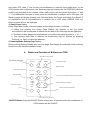
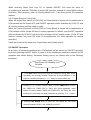
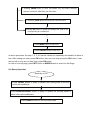
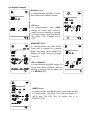
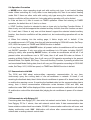
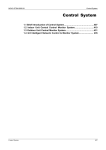
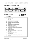
YDS04U-007aW
ENGLISH
OWNER’S MANUAL
YORK INTELIGENT NETWORK AIR-CONDITIONING
CENTRAL CONTROL MONITOR
AMR03M
Please read this installation manual carefully before installing your air conditioner.
Please keep this manual in a safe place for future reference.
This manual many be subject to change without notice for purpose of improvement.
2. Summarize of CCM
2-1 Basic Requirements
(1) Applicable Power Voltage Range: Input Voltage 220 ~ 240VAC±10%.
(2)AC Input Power Frequency: 50Hz/60Hz.
(3)Working Ambient Temp.: -10ºC ~ +43ºC.
(4)Working Ambient Humidity: RH40%~RH90%.
(5)CCM with Model YDSA-CCM01 is applicable to all models of YORK Air-conditioners.
2-2 Components of Central Control Monitor System
The Central Control Monitor System consists of CCM, (NIM), Electric Control, PC and
Communication Wire. Some NIM is inside the indoor PCB and needn’t set separately. (Please
refer to the technical information of indoor units.)
A/C
CCM
NIM
PC
Max 64
Internet
Max 16
The CCM can connect up to max 64 indoor units, which together compose one LAN
(Local Area Network), thus the CCM can central control to all air-conditioners in the LAN,
including sending every kind of control order to every air-conditioner and setting running
states of every air-conditioner. And the control
signal of CCM can arrive to the farthest 500
meters, which can meet various control
requirements for customers.
Through interfacing with PC or Gateway,
the CCM can realize central management
control, parameters setting and states query
to all air-conditioners in the LAN by PC.
What’s more, connecting with WAN (Wide
CCM
PC
CCM
Area Network) by PC or Gateway can realize
long-distance control. And every PC or
Gateway can connect max. 16 CCM.
Installation Sketch Map of Network Air-condition Building
3. Name and Function of Indicators on CCM LCD Screen
1) Common Display Data
Common display data will be indicated in all display pages.
a. Figure
means CCM is in network control with PC or Gateway.
b. Figure
means CCM is in communication connection with Function Module.
c. Figure
means CCM is in communication connection with Message Remote Control
Module.
d. Figure
means CCM is in communication connection with Telephone Remote
Control Module.
e. If CCM is in normal communication with NIM, then (Blank),
,
,
will be
displayed in dynamic circulation. Otherwise, no any display.
f. Lock Symbol
means the CCM is in Lock state or the buttons are in Lock state. ON
means the buttons are in Lock state or both CCM and Buttons are in Lock state, and 0.5
second flash means the CCM is in Lock state.
g. When setting page layout, if the selected air-conditioner is in Remote Controller Lock
state (in case that several air-conditioners are in operation, if only one is in Remote
Controller Lock state, then that means in Lock state.), symbol
in Mode Lock state, symbol
will display steadily. If
will flash in 0.5Hz. If Remote Controller Lock state and
Mode Lock state exist at the same time, symbol
will display steadily.
2) Display Data Treatment
Data Display area adopts 7-segment code, and there are 5 groups of 2-digital 7-segment
display.
a. TEMP. Display
TEMP. display is applicable to the following: Set Temp. Ts ( 17-30ºC ) , Indoor Return Air
Temp. T1, Evaporator Pipe Temp. T2A, Ev aporator Middle Pipe Temp. T2B, Condenser
Pipe Temp. T3. And the allowable data display range is 0ºC-99ºC. If higher than 99ºC,
then display 99ºC. If lower than 0ºC, then display 0ºC. What’s more, the real display range
also has relationship with the PCB temperature checking range. If no effective data, then
display “-“ and Unit symbol
will be ON.
b. CURRENT Display
CURRENT display is applicable to Compressor Current. The allowable range is 0A-99A.
If no effective data, then display “-“ and Unit symbol
mp. will be ON.
c. TIMER Display
TIMER is used to display the time of TIMER ON and TIMER OFF. The unit symbol
will be ON at the same time.
d. ERROR code display
ERROR is used to display malfunction warning data of the air-conditioner or the CCM.
The display range of ERROR code is E0-EF, where, E means ERROR, 0-F means
ERROR code, or Network ERROR display 00-0F#. If no EEROR, then display “E-“ and
will be ON.
e. PROTECT. code display
PROTECT. is used to display malfunction warning data of the air-conditioner or the CCM.
The display range of PROTECT. code is P0-PF, where, P means PROTECT., 0-F means
PROTECT. Code. If no PROTECT., then display “P-“ and
will be ON.
f. ADDRESS display
ADDRESS is used to display the ADDRESS code of the present selected air-conditioner.
will be ON.
The display range is 0-63, and at the same time
g. Number Display of Online air-conditioners and ON/OFF air-conditioners
It is used to display the number of online air-conditioners in LAN and ON/OFF
air-conditioners at present. The display range is 0-64.
h. Auxiliary function display
means ECONOMIC RUNNING,
means SWING,
means Auxiliary Heater,
means VENT.
i. Mode Confliction Display
Function Confliction display will flash at interval 1 second.
3)Stand-by Page Display
Stand-by page data consist of several pages and the page number is not fixed.
Stand-by page can display the total number of air-conditioners in network, under ON state
and under OFF state. If one or more air-conditioners in network have malfunction, or the
CCM checks other malfunctions, the Stand-by page will display the first ERROR Code from
small to big according to the number. Other malfunctions can be queried by buttons “+” and
“-“. If no malfunction and one or more online air-conditioners in network are in ON state, the
Stand-by page will display present main Running Mode, Set Temp. and Indoor Fan Speed. If
no malfunction and all air-conditioners in network are in OFF state, ERROR Code nor
Running mode will not be displayed.
4) Query Page Display
Query Page data consist of several pages and the page number is not fixed.
a. When first entering into Query Page Display, the address of the first online
air-conditioner will be selected in default and the data of the first page will be displayed.
b. The data of other pages can be displayed in circulation by pressing buttons “+” or “-”.
c. The running state data of different air-conditioners can be queried by pressing
“Previous” or “Next” to select the address.
5) Running Mode Setting Page Display
Running Mode Setting Display only has one page. And display the selected mode, auxiliary
function and the selected operation state.
4.
Name and Function of Buttons on CCM
Enter into the se tting sc re en
Check the running status of the A/C
Q UE RY
Confirm the ope ration
MOD E
T IM ER
FAN S PE E D
S WI NG
PRE VI O US
N EX T
T EM P
T IM ER
PAG E
+
-
OK
L OCK
R ES ET
Set the current time and off time
With or without swing
S ET
Cho ose the m ode
Adjust fan sp eed
In query or set mod e, Tra nsfer between previous and next unit.
Adjust the data s or pa g es
Rese t current unit to the default setting
Lock or unloc k curre nt A/C status
ON/OFF Button: Pressing ON/OFF Button at any time, all present online air-conditioners in
CCM network will be ON/OFF.
5. Operation and Performance of CCM
Before operating CCM, please first confirm the wiring of CCM, NIM, address setting of CCM
and the setup of the PC A/C Monitor Soft are in right state.
5-1 First Power On, Address Setting and State Display
5-1-1 Display when First Power On or Restore
After the CCM is power on or restore, first all display segment on LCD will be on and last 2
seconds, then all will be off. 1 second later, the system enters into normal display state, the
CCM is in the main page and display the data in the first page. When first power on, it only
can operate the buttons after 10 seconds.
5-1-2 Network Area Address Setting
The PC or gateway can connect max. 16 sets CCM. Every
CCM can be viewed as one network area and be distinguished
by dialing setting. The setting range is 0-15 ( 0-F) .
5-1-3 Indicator Display
If there is button to set the running state of air-conditioner, the
indicator lamp will be on when sending signal and will be off
after finishing setting.
If the online air-conditioner in network has malfunction, or the CCM network itself has
malfunction, the indicator lamp will flash in 2Hz.
If one or more online air-conditioners in network are in running state, including Timer
On/Timer Off setting running, the indicator lamp will be on. Otherwise, the indicator lamp will
be off.
5-2 Basic Function
5-2-1 Network Control Function
The CCM can control and adjust the states, parameters and ON/OFF of one or all indoor units
in network.
5-2-2 Lock Function of CCM and Remote Controller
When receiving CCM Lock order from PC, the CCM will not allow ON/OFF operation and
Mode Setting operation. At the same time, PC will send order of Remote Control Lock to all
air-conditioners in CCM network. When receiving Unlock order from PC, ON/OFF operation
will be carried out by CCM. At the same time, PC will send order to relieve the Remote
Control Lock of all air-conditioners.
Remote Control Lock: it can be Locked or Unlocked by PC separately, or it can be Locked or
Unlocked by the Lock button of CCM. When pressing Lock button of CCM, for one or more
indoor units, if the prior state is Lock, then Unlock; if the prior state is not Lock, then Lock.
5-2-3 Mode Lock Function
When receiving Mode Lock from PC to operate ON/OFF, first send the order to
air-conditioners, and the CCM allow to select ON operation method of Locked Mode without
confliction. After receiving order of relieving Mode Lock, it can freely select ON operation
method.
5-2-4 Urgent Stop and Forced ON
When the Urgent Stop switch of CCM (CN3 on Power Board) is closed, all air-conditioners in
CCM network will be forced OFF, and ON/OFF operation will be forbidden by CCM, PC and
all function modules until the switch is open.
When the Forced ON switch of CCM (CN2 on Power Board) is closed, all air-conditioners in
CCM network will be forced ON and in cooling operation in default, and ON/OFF operation
will be forbidden by CCM, PC and all function modules until the switch is open. (CCM, PC and
function modules only send ON order to air-conditioners, not effect operation by remote
controller.)
If both are closed at the same time, Urgent Stop switch takes priority.
5-3 ON/OFF Operation
At any time, all online air-conditioners in CCM network will be carried out ON/OFF operation
by directly pressing ON/OFF button. If some or all air-conditioners need to be carried out ON
operation after Mode Setting, Parameter Setting and so on, please refer to the following
procedure:
First Power ON, Stand-by or in
ON state
1.
Press SET button to enter into single air-conditioner setting state. Press
repeatedly, set circularly between single and all air-conditioners. If set
single air-conditioner,pressing “+” or “-“ button to select sertain one.
2. Pressing “+” or “-“ button to adjust Temp., or press TIMER button to enter
into TIMER ON, TIMER OFF or Temp. Set. Press repeatedly, select
buttons circularly between TIMER ON, TIMER OFF and Temp. Set. After
entering into one setting, set detail parameters by pressing “+” or “-“ button.
3. Pressing FAN SPEED button to enter into Fan Speed set, and select
circularly between AUTO, LOW, MIDDLE and HIGH.
4. Pressing MODE button to enter into MODE set, and select circularly
between COOLING, HEATING, and FAN ONLY.
5. Pressing LOCK button to lock remoto control function.
Pressing OK button to confirm all settings and send to the
corresponding air-conditioners.
Press MODE button to select OFF.
Press ON/OFF button to be OFF.
In above procedure, the step 1, 2, 3, 4,5 can be carried out separately and needn’t be done in
turn. After setting one step, press OK button; then set next step and press OK button. It can
also set all or only set one step, then press OK button.
In case of non-set page, press SET button or MODE button to enter into Set Page.
5-4 Query Operation
Stand-by or ON
Press QUERY button to query in default the running state of the first
online air-conditioner.
Press PREVIOUS/NEXT button to query in default the running states of
other online air-conditioners.
Press QUERY button to exit the query state.
5-6 Display Example
Stand-by state:
In communication with PC, 8 indoor
units online are in Stand-by state.
ON state:
In communication with CCM,
among 16 indoor units online,15
indoor units are starting or running
in Cooling mode, High Fan Speed,
Set Temp. 24ºC. I indoor unit is
OFF.
MODE SET state:
In communication with PC, NO.60
indoor unit in network is in Heating
mode, Set Temp. 28ºC, Middle Fan
Speed, 4.5 hours Timer-On,12 hours
Timer-Off.
ON and ERROR :
In communication with PC, among 16
indoor units online,15 indoor units are
starting or running. NO.38 indoor unit
is in ERROR. (E3).
QUERY state:
In communication with PC,58 indoor units online are ON
in Cooling mode, Set Temp. 18ºC, High Fan Speed, T3
(43ºC) and T2A(13ºC). NO. 39 indoor unit is in
PROTECT.(P2).
5-6 Operation Precaution
a. MODE button: when operating single unit with cooling only type, it can’t select Heating
mode. When controlling all, if only there is one heat-pump unit, then it can select Heating
mode. But if there are other units with cooling only type among the selected units, then
function confliction will be pointed out, but mode setting operation will not be limited.
b. If the set time is 0, then it means no TIMER operation. When first entering to TIMER
operation, the default time is 0, that is, no timer.
c. VENT. Auxiliary function is selected to start or close only by Auxiliary Function Button. If
there is only one unit that supports the selected auxiliary function, then this function can start.
Or, it can’t start. If there is only one unit that doesn’t support the selected started auxiliary
function, then function confliction will be pointed out, but mode setting operation will not be
limited.
d. When first entering into the setting page, it thinks single unit in default. If the
air-conditioners are in OFF state, then they will start according to COOLING mode, Set Temp.
24ºC, HIGH fan speed, no TIMER and SWING function in default.
e. At any time, if pressing ON/OFF button, all present online air-conditioners will be carried
out ON/OFF operation. If only one online air-conditioner is in ON state, including ON/OFF
setting by delay, after pressing ON/OFF button, all online air-conditioners will be off. If all
present online air-conditioners are in OFF state, then it will send ON order as follows: if
pressing at Mode Setting Page, then it will carry out ON operation according to the present
selected Mode, Fan Speed, Set Temp., Timer and Auxiliary Function; if pressing at other time
and no selected Mode Setting data, then it will carry out ON operation according to COOLING
mode, Set Temp. 24ºC, HIGH fan speed, no TIMER and SWING function in default.
5-7 Communicate with NIM
The CCM and NIM adopt main-auxiliary responsion communication. At any time,
continuously query the running state of one air-conditioner in network 10 times, if not
receiving the feedback data, then it thinks this air-conditioner is power off or doesn’t exist, and
no malfunction warning occurs. If receiving the feedback data, but the communication data is
wrong, then it thinks communication malfunction exists between CCM and NIM, and
malfunction code “01#” will be displayed. After normal communication, malfunction will relieve.
Or malfunction code will be eliminated after judging the air-conditioner is power off or doesn’t
exist.
5-8Communicate with Epigyny PC
If receiving data from Epigyny PC, then enter into network control state. If not receiving data
from Epigyny PC for 1 minute, then exit network control state. If data communication has
frame mistake or data check has mistake, CCM/PC communication malfunction will occur and
display malfunction code “03#”. Malfunction will relieve after communication restores to
normal state or exiting network control state.
5-9 Data Communicate with other Function Modules
If receiving data from function module, then display the network information of the
corresponding function module. If not receiving data from corresponding function module for
1 minute, then exit network control state. If data communication has frame mistake or data
check has mistake, CCM/PC communication malfunction will occur and display malfunction
code “02#”. Malfunction will relieve after communication restores to normal state or exiting
network control state.
6.
ERROR
Code
Malfunction and Protection Code Table
ERROR Contents
PROTECT.
Code
PROTECT. Contents
EF
Other malfunction
PF
Other Protection
EE
Water level checking malfunction
PE
Reserve
ED
Outdoor protection
PD
Reserve
EC
Clear malfunction
PC
Reserve
EB
Inverter Module Protection
PB
Reserve
EA
Compressor Over-current (4 times)
PA
Reserve
E9
Communication malfunction
between PCB and Display board
P9
Reserve
E8
Fan motor checking out of control
P8
Compressor Over-current
E7
EEPROM malfunction
P7
Power Lack/Over Volt Protection
E6
Over-zero checking malfunction
P6
Discharge Low-pressure Protection
E5
T3 sensor malfunction
P5
Discharge High-pressure Protection
E4
T2B sensor malfunction
P4
Discharge Pipe Temp. Protection
E3
T2A sensor malfunction
P3
Compressor Temp. Protection
E2
T1 sensor malfunction
P2
Condenser High Temp. Protection
E1
Communication malfunction
P1
Anti-cooling or Defrost Protection
E0
Phase sequence or lack of phase
P0
Evaporator Temp. Protection
03#
CCM/PC(gateway) Communication Malfunction
02#
CCM/Function Module Communication Malfunction
01#
CCM/NIM Communication Malfunction
00#
CCM/PCB Communication Malfunction
7.
Technical Index and Requirement
EMC and EMI should conform to the requirement of CE Certification.
DE - COMMISSIONING DISMANTLING & DISPOSAL
This product contains refrigerant under pressure, rotating parts, and electrical connections which
may be a danger and cause injury!
All work must only be carried out by competent persons using suitable protective clothing and safety precautions.
Read the Manual
Risk of electric shock
Unit is remotely controlled
and may start without warning
1. Isolate all sources of electrical supply to the unit including any control system supplies switched by the unit. Ensure that all points of electrical and gas
isolation are secured in the OFF position. The supply cables and gas pipework may then be disconnected and removed. For points of connection refer
to unit installation instructions.
2. Remove all refrigerant from each system of the unit into a suitable container using a refrigerant reclaim or recovery unit. This refrigerant may then be
re-used, if appropriate, or returned to the manufacturer for disposal.Under No circumstances should refrigerant be vented to atmosphere. Where
appropriate, drain the refrigerant oil from each system into a suitable container and dispose of according to local laws and regulations governing
disposal of oily wastes.
3. Packaged unit can generally be removed in one piece after disconnection as above. Any fixing down bolts should be removed and then unit lifted from
position using the points provided and equipment of adequate lifting capacity. Reference MUST be made to the unit installation instructions for unit
weight and correct methods of lifting. Note that any residual or spilt refrigerant oil should be mopped up and disposed of as described above.
4. After removal from position the unit parts may be disposed of according to local laws and regulations.
YDS04U-007aW
ENGLISH