1
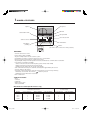
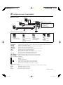
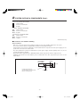
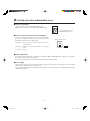
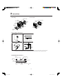
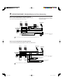
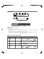
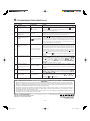
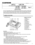
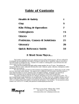
P0015311A0109Y
LEF-3L
3-Call Master Station with Selective Control Capability (Door Release or Camera Call-up)
Used with LE-D, LE-DA, LE-DL, LS-NVP/C Door Stations
- SUPPLEMENT TO LEF INSTRUCTIONS The LEF-3L is a compact, wall or desk mount master station able to selectively release a door or call up a camera.
Used with any LE-(except LEF-3,5 and 10) or LS-series (North America only) remote station, communication can be
established with each station by selecting the channel on the master station. While the channel is selected, pressing
the door release button (left of TALK button) will release only the associated door. When used for camera call-up, a relay
closure will be maintained as long as a station is selected. The system can have up to four stations, in any combination of
masters or door stations (e.g. 2 masters and 2 doors). Master-to-master communication is also a standard feature.
(If communication between masters is not required, multiple LEF-3L's can be used to talk to 3 door stations.)
PRECAUTIONS
General Prohibitions
Prohibition to Dismantle the Unit
Prohibition on Subjecting the Unit to Water
General Precautions
WARNING (Negligence could result in death or serious injury.)
1. Do not dismantle or alter the unit. Fire or electric shock could result.
2. Do not connect any non-specified power source to the +, - terminals, and do not install two power supplies in
parallel to a single input. Fire, damage to the unit, or system malfunction could result.
3. Keep the unit away from water or any other liquid. Fire or electric shock could result.
4. When existing chime wires are used, it is possible that they contain AC voltage. Electric shock or unit damage
could result. Ask a qualified technician.
5. Do not use DC power supply with a voltage other than specified. Fire or electric shock could result.
CAUTION (Negligence could result in injury or damage to property.)
1. Before turning on the power, make sure wires are not crossed or shorted. Fire or electric shock could result.
2. When mounting the unit on wall, install the unit in a convenient location, but not where it could be jarred or
bumped. Injury could result.
3. For DC powered systems, use Aiphone power supply model specified with system. If non-specified product is
used, fire or malfunction could result.
4. Do not install or make any wire terminations while power supply is plugged in. It can cause electrical shock or
damage to the unit.
5. In case of electrical storms, unplug the unit from AC outlet. If not, fire or electric shock could result.
6. Do not install the unit in any of the following locations. Fire, electric shock, or unit trouble could result.
* Places under direct sunlight, or near heating equipment that varies in temperature.
* Places subject to dust, oil, chemicals, hydrogen sulfide (hot spring).
* Places subject to moisture and humidity extremes, such as bathroom, cellar, greenhouse, etc.
* Places where the temperature is quite low, such as inside a refrigerated area or in front of air-conditioner.
* Places subject to steam or smoke (near heating or cooking surfaces).
* Where noise generating devices such as dimmer switches, invertor electrical appliances, are closeby.
7. Do not install the unit in a location subject to constant vibration or impact. If dropped, injury or unit damage
could result.
GENERAL PRECAUTIONS
1. Keep the unit more than 1 m (3.3') away from Radio or TV set.
2. In areas where broadcasting station antennas are close by, the intercom system may be affected by radio
frequency interference.
3. The unit will be inoperative during a power outage.
4. This unit is for indoor use only. Do not use outdoors.
–1–
aiphone_e.indd 1
09.2.17, 2:13:51 PM
1NAMES & FEATURES
Microphone
Speaker
ON LED
Station Call-in LEDs
Occupied LED
.
11
.
22
33
.
. OFF
OFF OCCUPIED
OCCUPIED
Door Release LED
CALL
PRIV
TALK
TALK
Station Selectors
VOICE VOL.
LEF-3L
TALK Button
OFF Button
(standby)
Voice Volume Control
Door Release (
) Button
(The LEF-3L does not have the "Privacy feature")
VOICE VOL.
Low
High
FEATURES:
·
·
·
·
·
·
·
·
·
·
·
Selective door release control
CCTV camera call-up capability
Single or multiple masters can be used in a system
Intermixable, any number of masters and remotes up to 4 total stations
Master to master communication in a multi-master system
Single talkpath, with push-to-talk operation at master, and hands free communication at sub station
Large variety of sub stations available
- Surface or flush mount, with or without privacy (LE-A, LE-AN, LE-B, LE-BN)
- Weather resistant door stations (LE-D, LE-DA, LE-DL)
- Vandal proof sub stations (LE-SS, LE-SSR & LS-NVP/C)
Subs call in with momentary tone and LED, remaining lit for approximately 20 seconds
Selective calling to sub stations
Selectively control external device from the master station in one of two ways with relay
- Momentary closure while “Door release (
)” button is pressed
- Maintained closure while station is selected
Desk or wall mount
SOME APPLICATIONS:
·
·
·
·
·
Offices
Courthouses
Hotels/Motels
Retail/Convenience Stores
Small Secured Facilities
Wire Reference Chart (North America only)
With selective door release and/
or camera call-up
Standard Communication
Model #
# of Conductors
Wire # (22AWG)
Wire # (18AWG)
# of Conductors
Wire # (22AWG)
LEF-3L
9
LE-A
3
822210
x
12
822212
822203
821803
x
x
LE-D
3
822203
821803
x
x
LE-DA
3
822203
821803
x
x
–2–
aiphone_e.indd 2
09.2.17, 2:13:53 PM
2
■
SYSTEM OUTLINE & COMPONENTS
System outline
LE-D
2
LEF-3L
LE-D
■
Door Strike
PT
2
2
2
RY-PA
2
RY-PA
2
• LEF-3L
• Packet of screws
• Installation &
Operation Manual
PT
LE-D
Door Strike
2
2
2
RY-PA
PT
Door Strike
Package contents
2
Door release button
PT : AC Transformer
PS-12
Individual Components for LEF-3L System:
(LE-D)
LEF-3L 3-call master with
selective door release
LE-D Surface mount door station
LE-DL
Surface mount door station
(Aluminum)
LE-DA Flush mount door
station with stainless
steel faceplate
LE-A
1-call sub station
LE-A3
3-call sub station
* : North America only
*LS-NVP/C *LE-SS *LE-SSR *SBX-2G *LE-SS-1G *SA-1 RY-PA Vandal and weather resistant sub station, white powder coated (optional SBX-NVP surface box)
Stainless Steel 2-Gang sub station
Stainless Steel 2-Gang sub station with red mushroom push button
Surface mount box for LE-SS and LE-SSR Stainless Steel 1-Gang sub station (optional SBX-SS-1G surface box)
Surge Arrestor (1 per 2 wires being protected)
Relay, 12V DC input, N/O dry closure output.
One required for each contact closure required off of each channel.
Can be momentary or maintained, according to wiring.
12-18V DC “Form C” relay (N/O and N/C contacts)
*RY-18L PS-1225/UL/S 12V DC, 2.5A power supply, use for intercom only, 1 per system
PS-1215DIN 12V DC, 1.5A power supply, use for intercom only, 1 per system
LEF-3L TERMINAL DEFINITIONS:
Positive 12V DC
+ Negative
− Common communication
E Station number, communication to sub or other master
1 ∼ 3 "CALL", for receiving a call from another master station
C Occupied light control (0V DC when system is occupied)
R COLOR-CODED WIRES:
White
Common Door release activation (+12V DC when door release button is pressed) Brown
Ground when station 1 is pressed
Red
Ground when station 2 is pressed Orange Ground when station 3 is pressed
* North America only
–3–
aiphone_e.indd 3
09.2.17, 2:13:55 PM
2
SYSTEM OUTLINE & COMPONENTS (Cont.)
LE-D/LE-DA TERMINAL DEFINITIONS:
Station number
1 Common communication
E Negative
− *LS-NVP/C TERMINAL DEFINITIONS:
Red
Station number
Black Common communication
Green Negative
*LE-SS(R)/LE-SS-1G COLOR CODE:
Red Station number
Black Common communication
Green Negative
* North America only
■ Precautions on Installation & Wiring
Before Installation:
· Make sure you have the proper power supply(ies) and all necessary and compatible equipment for the system.
· Lay out your system in advance, assigning station numbers for all sub station locations.
· Surge protection for the intercom equipment is recommended. Add SA-1 surge arrestors for the power supply, plus one
per two wires connected to the master station.
· Any other manufacturer's products installed with this system (power supply, external signaling device, etc.) are not
covered under Aiphone's warranty.
· When using a power supply that has no GROUND terminal, install a surge arrestor near the output as shown.
· Additional surge arrestors can be installed to protect communication lines. One surge arrestor per 2 wires on each
master station.
PS-1225/UL/S
PS-1215DIN
LEF-3L
DC 12V
Surgearrestor
Install a surge-arrestor
at a location closest to the unit,
taken to earth ground.
Grounded
–4–
aiphone_e.indd 4
09.2.17, 2:14:05 PM
Wire:
· Shielded wire is strongly recommended. Use the proper gauge for the distance being run.
· Wiring between masters must be a multi-conductor cable. If more than one cable is used to connect masters, the "E",
"C", and number terminal wires must be in the same jacketed cable. If necessary, run multiple "E" wires, one in each
cable.
Wiring Method:
· Run intercom cables at least 50cm (20") away from all AC wiring, fluorescent lights, dimmer switches, and other
electrical or electronic devices. Intercom wiring can cross AC wires at 90 degrees.
· Sub stations can be homerun to the nearest master station, or daisy-chained. If daisy-chained, include 2 common wires
plus 1 individual wire per station on the run.
· In a SINGLE MASTER SYSTEM ONLY: Subs can be wired with 2 conductors homerun. Jumpers between "E" and "-"
must be attached on all subs and at the master station.
Intercom Locations:
· Do not install intercoms near dimmer or light switches, or other electrical wall devices.
· To prevent feedback, do not place sub stations back-to-back on a common wall.
· Near alarm panels or other electronic equipment that may emit data noise.
· Behind a doorway or any other area that may block access to the unit.
■ Before actually installing the LEF system, Precautions on Installation & Wiring must be
thoroughly read and understood.
To access the inside of the unit for making wire connections:
1. Remove Operation plate & Directory card and loosen the screw on the front of the unit. (Do not remove
screw)
2. Carefully lift front of intercom up and off the back chassis.
3. If desired, unplug connectors and set unit aside during mounting and wiring of the back chassis.
4. When wiring is completed, plug in connectors and put unit back together. Peel protective covering off of Operation
plate.
To remove the operation
plate, push either left or
right side of the plate.
Directory card
Operation plate
PUSH
–5–
aiphone_e.indd 5
09.2.17, 2:14:07 PM
2
SYSTEM OUTLINE & COMPONENTS (Cont.)
■ Call tone adjustment
3-position volume switch, located under Operation plate.
Adjusts call tone volume to low (far left), medium, high (far right).
3-pos. call tone vol. switch
(under Operation plate)
CALL
LEF-3L
■ Selector switch for Call Tone in Occupied Mode
LEF surface mount master stations are set in the "B" position from
the factory. This allows a sub call-in tone to be heard at a muted
level while the master is in the occupied mode.
“A” position:
Mutes call tone at master while system is in
occupied mode.
“B” position:
Call tone is heard when master is in occupied
mode.
(FRONT CASE BACK VIEW)
A
LEF-3L
B
(when shipped)
*No call tone between masters.
■ Cable requirements
Use multi-conductor cable with an overall shield, non-twisted, 22AWG to 18AWG (0.65mm to 1.0mm), to accommodate
the maximum number stations in the system.
Use the gauge specified for the maximum distance between the two farthest stations.
■ Power supply
The entire LEF system can be powered by one power supply (PS-1225UL/PS-1225S 12VDC 2.5A or PS-1215DIN
12VDC 1.5A), located near the center of the wire run.
For a system including the All Call and Chime with the BG-10C, one PS-1225UL(S) or PS-1215DIN will power the BG10C and the LEF system.
–6–
aiphone_e.indd 6
09.2.17, 2:14:09 PM
3
MOUNTING
Back wiring
LE room subs
★1
Unplug
while installing
SINGLE-GANG
BOX
SINFGLE-GANG BOX
Mounting
bracket
83.5mm,
3-5/16"
LEF-3L
intercom
UP
2 screws
supplied
83.5mm,
3-5/16"
Directory
card
Chassis
(LE-A)
★2
2 screws
supplied
Loosen
Operation
plate
Surface wiring or Desk-top use
Surface wiring
wall
Cut out the cable inlet section
Bottom view of LEF-3L
Clamp
Desk-top use;
Cable
Back
view
★ 1, 2 : When running cable on the surface, pass cable through the top or bottom of the chassis and fasten with the wire clamps (attached,
one outside and one inside chassis). To pass the cable through the bottom side of the unit, cut out the cable inlet section.
OPERATION PANEL FOR LEF-3L
Station
Call-in LEDs ON LED
Operation
plate
1
2
Occupied LED
Door release LED
3
OFF OCCUPIED
Stationselector (3)
TALK
TALK button
AIPHONE
LEF-3L
Voice vol.
Control
VOICE VOL.
OFF button
(standby)
Door release (
) button
–7–
aiphone_e.indd 7
09.2.17, 2:14:11 PM
4
WIRING DIAGRAMS - Most Common Applications
IMPORTANT: When using selective outputs, a separate relay and power source
are required. Do not power external devices off of the system
power supply.
1 x LEF-3L, 3 x Door Stations
WIth Selective Door Release
Door #1
LE-D/LE-DA
LEF-3L
PS-1225/UL/S
PS-1215DIN
–
+
12V DC
POWER
ONLY
1
2
3
E
–
+
C
R
Y
White
Brown
Red
Orange
Door #2
LE-D/LE-DA
Door #3
LE-D/LE-DA
NOTE:
When running 2 conductors
homerun to each sub (single master
system only), leave jumper attached
between E & — on master and
door stations. Otherwise, remove
jumpers and use separate wires for
E and — terminals.
1
1
E
–
12V DC when "Door release (
Black
RY-PA
for #1
1
E
–
E
–
Yellow A
Black
)" button is pressed
RY-PA
for #2
Yellow A
AC Transformer
Black RY-PA
for #3
AContact Rating: AC110V 1A
DC24V 1A
A
Yellow
2 x LEF-3L, 2 x Door Stations
With Master to Master communication shown on channel 3
With Selective Door Release
LEF-3L
PS-1225/UL/S
PS-1215DIN
–
+
12V DC
POWER
ONLY
LEF-3L
1
2
3
C
E
–
+
R
Y
White
1
2
C
3
E
–
+
R
Y
White
Brown
Red
Brown
Red
Orange
Orange
Door #1
LE-D/LE-DA
Door #2
LE-D/LE-DA
1
1
E
–
AContact Rating: AC110V 1A
DC24V 1A
E
–
AC Transformer
Black
RY-PA
for #1
Yellow A
Black
RY-PA
for #2
A
Yellow
To prevent shorts, be sure to cut unused lead wires at the button and insulate the ends.
2 x LEF-3L, 1 x Door Station
With Master to Master Communication
Door Station wired on each station's own number terminal (different on each master)
LEF-3L
Optional Remote station:
LEF-3L
LE-D/LE-DA
PS-1225/UL/S
PS-1215DIN
–
+
12V DC
POWER
ONLY
C
2
3
1
E
–
+
R
Y
White
Brown
Red
Orange
1
C
3
2
E
–
+
R
Y
White
Red
Brown
Orange
LEF-3L
LS-NVP
LE-SS
#
E
-
Red
Black
Green
1
E
–
12V DC when "Door release (
button is pressed
)"
A
Black
RY-PA
AContact Rating: AC110V 1A
DC24V 1A
Yellow
AC Transformer
To prevent shorts, be sure to cut unused lead wires at the button and insulate the ends.
–8–
aiphone_e.indd 8
09.2.17, 2:14:13 PM
4
WIRING DIAGRAMS - Multiple Masters for Door Answering
IMPORTANT: When using selective outputs, a separate
relay and power source are required.
Do not power external devices off of the
system power supply.
LEF-3L System with External Signaling (RY-AC)
One door station with the ability to activate a separate doorbell
Shown with external signaling and door release relays
LEF-3L
LEF-3L
LE-D/LE-DA
AC Transformer
PS-1225/UL/S
PS-1215DIN
–
+
12V DC
POWER
ONLY
C
2
3
1
E
–
+
R
Y
White
Brown
Red
Orange
1
C
3
2
E
–
+
R
Y
White
Brown
Red
Orange
White
Red
Black
RY-AC
External
Sounder
Yellow
1
E
–
A
Black
RY-PA
Yellow
AContact Rating: AC110V 1A
DC24V 1A
AC Transformer
To prevent shorts, be sure to cut unused lead wires at the button and insulate the ends.
LEF-3L System with External Signaling (RY-AC)
Selective external signaling relay outputs for each door station call-in
LEF-3L
LE-D/LE-DA
LEF-3L
LE-D/LE-DA
PS-1225/UL/S
PS-1215DIN
–
+
12V DC
POWER
ONLY
1
2
C
3
E
–
+
R
Y
White
1
2
3
C
E
–
+
R
Y
White
Brown
Red
Orange
Brown
Red
Orange
1
1
E
–
E
–
White
Black
Red
Contact Rating: 0.3A、240V AC
1.0A、24V DC
RY-AC
To External signaling
device & power
Yellow
White
Black
Red
RY-AC
Yellow
To External signaling
device & power
To prevent shorts, be sure to cut unused lead wires at the button and insulate the ends.
–9–
aiphone_e.indd 9
09.2.17, 2:14:16 PM
5
OPERATIONS & SPECIFICATIONS
OPERATIONS:
■ Calling a master or sub:
1. Depress a station selector button 1 ~ 3.
2. Press the TALK button to speak, and release to listen to the reply.
3. To conclude, depress OFF button.
■ Receiving a call from a sub station:
1.
2.
3.
4.
5.
Sub station calls in with tone and LED, which stays lit for 20 seconds.
Depress the lit station selector button.
Press the TALK button to speak, and release to listen.
Communication at the door station is hands free.
Depress OFF button when finished.
■ Receiving call from another master:
1. When a master calls to another master (without tone & LED), the responding master answers back handsfree.
2. The Occupied lamp will be on while the initiating master has a station selected.
3. Do not press any buttons on the master when responding to another master's call.
■ Door answering (from a master station only):
1. Audio door station calls in with an electronic call tone & LED, which stays lit for 20 seconds.
2. Depress the lit selector button, then press TALK to speak, release to listen.
■ Door release with “LOCK” button:
LEF-3L provides selective door release to multiple doors (One RY-PA for each door). When communication is
) button to release the corresponding door strike.
established to a door station, press the Door release (
■ Camera Call-up feature:
If the "Camera Call-up" feature is included, the associated relay will provide a maintained closure as long as the station
is selected at the master.
NOTE:
The LEF-3L does not have the "privacy feature", and also cannot send a call tone to another master or remote station in the system.
SPECIFICATIONS:
Power Source:
12V DC at master. Use PS-1225, 1225UL, 1225S (2.5A) or PS-1215 DIN (1.5A). Do not use AC
power. Damage to the unit will result.
Current Consumption: 440mA
Communication Output: 800mW @ 20 ohms (receive); 500mW @ 20 ohms (transmit)
Communication:
Push-to-talk, release-to-listen at master station (LEF-3L). Hands free at sub station.
Calling:
Master to sub: By voice
Sub to master: Call tone and LED
Wiring:
2 common plus 1 individual per sub, looped; or 3 conductors homerun from each sub.
2 conductors homerun from each sub in a single-master system only.
Use Aiphone #822202 or #821802 ( 2 cond., 22 or 18AWG), or #822203 (3 cond. 22AWG)
12 conductors between master stations. Use Aiphone #822212. (North America only)
Shielded cable is strongly recommended.
– 10 –
aiphone_e.indd 10
09.2.17, 2:14:18 PM
WIRING DISTANCE:
D1
M1
M2
PS
M3
D2
–
+
12V DC
POWER ONLY
RY-PA
A
Figure 1
PS
–
+
12V DC
POWER ONLY
B
Figure 2
Wire
WIRING DISTANCE
Distance(MAX)
φ 1.0 mm(18AWG)
A
480 m(1575’
)
B
240 m(780’
)
Dimensions (HxWxD): 180H x 143W x 53.5D (mm). 7-1/16" x 5-5/8" x 2-1/8"
RY-PA Contact Rating: 1A, 110V AC or 24V DC
RESTRICTIONS
· Only one power supply can be used on one system.
· Up to 4 masters can be connected on the multiple masters confi guration, or up to 3 masters on the intermix
configuration.
· Use the door release button only when the TALK button is not pressed. (Don't operate the door release when talking.)
Proper (relay) operation may not be guaranteed under the following conditions.
· When a master is called from another sub or master station while talking (Including when the Call tone is sounding)
· When a master is called from another master while the OCCUPIED lamp is on
6
ENTRY #
1
2
3
4
TROUBLESHOOTING GUIDE
PROBLEM
POSSIBLE CAUSE
SOLUTION
Door station does not call
in (no call tone or LED
light).
Missing jumpers
Door station does not call
in (no call tone or LED
light) -- 3-wire connection.
Missing connection of —
terminal.
Door station does not call
in (no call tone or LED
light) -- 3-wire connection.
Mis-wiring of 1 and E
terminals.
Check that the 1 and E wire are not reversed. If they are, communication
will work but call-in will not.
No communication to
door station.
Mis-wiring of E
terminal.
Communication is between the 1 and E terminal of the door station to a #
and E terminal of the master station. If call-in works, check the E wire for
continuity. Check the 1 and E wires at the sub to ensure that they are not
reversed.
Are there 2 or 3 conductors run to the door station? If 2 wires, jumper must
remain attached between E and — at both the door station and the master
station. Replace jumper. In a multi-master system, the E / — jumper
should be removed and 3 wires should be connected.
If communication works, check connection between — terminal of door
station and master. Test call-in at master station by touching a jumper wire
between # and — terminal of master. If this rings the tone and lights the
light, the — wire from the door station is not connected properly.
– 11 –
aiphone_e.indd 11
09.2.17, 2:14:22 PM
6
ENTRY #
5
6
7
TROUBLESHOOTING GUIDE (Cont.)
PROBLEM
No master-to-master
communication.
LEF master has no
communication or tone, but
LED lights work.
Feedback when the volume
control is turned up over
halfway.
POSSIBLE CAUSE
Communication between masters is carried on the # wire of the calling
C terminals mis-wired
between masters.
The LED lights will operate with a power source from 6VDC - 24VDC. The
amplifier in the LEF unit will only work when the system is supplied 12VDC.
Proper power supply is the PS-1225/UL/S, or PS-1215 DIN.
E / — jumpers attached
in a multi-master system.
Remove E / — jumpers on masters and door stations in the system,
provided there are 3 wires to the sub(s). If the sub only has 2 wires in a
multi-master system, the jumper must remain in place for the door call-in to
work. In this case, the side effect is the feedback problem when the audio
volume is turned up. The only alternative is to run the proper wire to the
door station(s) and remove all of the jumpers.
Too close to AC and/or
incorrect wire was used.
Door release does not work.
9
10
No call tone between
masters.
No Privacy feature on LEF3L.
11
Can't release the door from
the 2nd (additional masters)
12
External Signaling device
doesn't activate
master to the C terminal of the receiving master. Verify that the C terminal
of the master that is being called is actually wired to the #terminal that is
being selected on the calling master.
Wrong power supply is
being used.
New installation has AC
buzz, noise, or hum in
system.
8
SOLUTION
If the units are too close to an AC source such as AC wiring or dimmer
switches, move the intercom at least one stud space away from the AC
source. Other precautions include using shielded cable. If shielded wire was
used and there is still AC noise, tie all the shields together and ground to
an earth ground or negative on the power supply. If more than one jacketed
cable was used between masters, make sure the # terminals, C terminal,
and the E terminals are all in the same jacketed cable. If multiple cables
were used, include an E wire in each cable that carries a station number
wire in it.
Miswire or lack of RY-PA
relays.
Check the WHITE wire coming out of the PC board for voltage. When
) button, 12VDC is present across WHITE
depressing the Door release (
and — , which activates the relay. Ensure that the BLACK wires of the
RY-PA are connected to WHITE and either the BROWN , RED , or
ORANGE wire for selective door release (which provides selective ground
when the corresponding channel is selected).
Features not available
The LEF-3L unit does not have the PRIVACY feature or the ability to send
a call tone to another master station (as with the standard LEF-3). This
function is removed to allow the switch to be used for door release instead
of privacy.
Wiring not connected
properly.
If door release works from the first master but not another(s), verify that
selective door release wires are connected between masters. ( WHITE ,
BROWN , RED , ORANGE ). RY-PA's are only required at one master.
Make sure that the WHITE wire of the RY-AC is connected to the #
RY-AC mis-wired
terminal that is to be activating the relay, and that RED and BLACK are
connected to
+
and — , respectively.
WARRANTY
Aiphone warrants its products to be free from defects of material and workmanship under normal use and service for a period of one year after
delivery to the ultimate user and will repair free of charge or replace at no charge, should it become defective upon which examination shall
disclose to be defective and under warranty. Aiphone reserves unto itself the sole right to make the final decision whether there is a defect in
materials and/or workmanship; and whether or not the product is within the warranty.
This warranty shall not apply to any Aiphone product which has been subject to misuse, neglect, accident, or to use in violation of instructions
furnished, nor extended to units which have been repaired or altered outside of the factory. This warranty does not cover batteries or damage
caused by batteries used in connection with the product.
This warranty covers bench repairs only, and any repairs must be made at the shop or place designated in writing by Aiphone. Aiphone will not be
responsible for any costs incurred involving on site service calls.
AIPHONE CO., LTD., NAGOYA, JAPAN
AIPHONE CORPORATION, BELLEVUE, WA, USA
AIPHONE S.A.S., LISSES-EVRY, FRANCE
http://www.aiphone.com/
Printed in Japan (E)
– 12 –
aiphone_e.indd 12
09.2.17, 2:14:25 PM