1
4
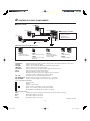
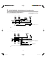
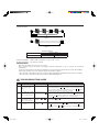
WIRING DIAGRAMS - Most Common Applications
IMPORTANT: When using selective outputs, a separate relay and power source
are required. Do not power external devices off of the system
power supply.
1 x LEF-3L, 3 x Door Stations
WIth Selective Door Release
Door #1
LE-D/LE-DA
LEF-3L
PS-1225/UL/S
PS-1215DIN
–
+
12V DC
POWER
ONLY
1
2
3
E
–
+
C
R
Y
White
Brown
Red
Orange
Door #2
LE-D/LE-DA
Door #3
LE-D/LE-DA
NOTE:
When running 2 conductors
homerun to each sub (single master
system only), leave jumper attached
between E & — on master and
door stations. Otherwise, remove
jumpers and use separate wires for
E and — terminals.
1
1
E
–
12V DC when "Door release (
Black
RY-PA
for #1
1
E
–
E
–
Yellow A
Black
)" button is pressed
RY-PA
for #2
Yellow A
AC Transformer
Black RY-PA
for #3
AContact Rating: AC110V 1A
DC24V 1A
A
Yellow
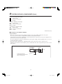
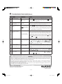
2 x LEF-3L, 2 x Door Stations
With Master to Master communication shown on channel 3
With Selective Door Release
LEF-3L
PS-1225/UL/S
PS-1215DIN
–
+
12V DC
POWER
ONLY
LEF-3L
1
2
3
C
E
–
+
R
Y
White
1
2
C
3
E
–
+
R
Y
White
Brown
Red
Brown
Red
Orange
Orange
Door #1
LE-D/LE-DA
Door #2
LE-D/LE-DA
1
1
E
–
AContact Rating: AC110V 1A
DC24V 1A
E
–
AC Transformer
Black
RY-PA
for #1
Yellow A
Black
RY-PA
for #2
A
Yellow
To prevent shorts, be sure to cut unused lead wires at the button and insulate the ends.
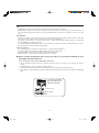
2 x LEF-3L, 1 x Door Station
With Master to Master Communication
Door Station wired on each station's own number terminal (different on each master)
LEF-3L
Optional Remote station:
LEF-3L
LE-D/LE-DA
PS-1225/UL/S
PS-1215DIN
–
+
12V DC
POWER
ONLY
C
2
3
1
E
–
+
R
Y
White
Brown
Red
Orange
1
C
3
2
E
–
+
R
Y
White
Red
Brown
Orange
LEF-3L
LS-NVP
LE-SS
#
E
-
Red
Black
Green
1
E
–
12V DC when "Door release (
button is pressed
)"
A
Black
RY-PA
AContact Rating: AC110V 1A
DC24V 1A
Yellow
AC Transformer
To prevent shorts, be sure to cut unused lead wires at the button and insulate the ends.
–8–
aiphone_e.indd 8
09.2.17, 2:14:13 PM