1
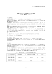
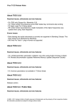
HARMONY PROCESSING UNIT
WARNING!!
To prevent fire or shock hazard, do not expose this appliance to rain or moisture.
1-En
CAUTION
RISK OF ELECTRIC SHOCK
DO NOT OPEN
CAUTION: TO REDUCE THE RISK OF ELECTRIC SHOCK,
DO NOT REMOVE COVER (OR BACK).
NO USER-SERVICEABLE PARTS INSIDE.
REFER SERVICING TO QUALIFIED SERVICE PERSONNEL.
THE SYMBOLS ARE RULED BY UL STANDARDS (U.S.A.)
The lightning flash with arrowhead symbol , within an equilateral triangle, is
intended to alert the user to the presence of uninsulated “dangerous voltage”
within the product’s enclosure; that may be of sufficient magnitude to constitute
a risk of electric shock to persons.
The exclamation point within an equilateral triangle is intented to alert the user
to the presence of important operating and maintenance (servicing) instructions in the literature accompanying the appliance.
5B-En
06/24/2002 Rev. 4
Duo Buddy HV1
vii
WARNING
WARNING
The HV1 is designed to be used in a standard household environment.
Power requirements for electrical equipment vary from area to area. Please ensure that your AC
Adaptor supplied meets the power requirements in your area. If in doubt, consult a qualified
electrician or AKAI professional dealer.
120 VAC
220~230 VAC
@ 60 Hz for USA and Canada
@ 50 Hz for Europe
PROTECTING YOURSELF AND THE HV1
•
Never touch the AC Adaptor with wet hands.
•
Always disconnect the AC Adaptor from the power supply by pulling on the adaptor/plug,
not the cord.
•
Allow only an AKAI professional dealer or qualified professional engineer to repair or
reassemble the HV1. Apart from voiding the warranty, unauthorized engineers might touch
live internal parts and receive a serious electrical shock.
•
Do not put, or allow anyone to put any object, especially metal objects, into the HV1.
•
Use only a household AC power supply. Never use a DC power supply.
•
If water or any other liquid is spilled into or onto the HV1, disconnect the power, and call your
dealer.
•
Make sure that the unit is well-ventilated, and away from direct sunlight.
•
To avoid damage to internal circuitry, as well as the external finish, keep the HV1 away from
sources of direct heat (stoves, radiators, etc.).
•
Avoid using aerosol insecticides, etc. near the HV1. They may damage the surface, and may
ignite.
•
Do not use denaturated alcohol, thinner or similar chemicals to clean the HV1. They will
damage the finish.
•
Modification of this equipment is dangerous, and can result in the functions of the HV1 being
impaired. Never attempt to modify the equipment in any way.
•
Make sure that the HV1 is always well-supported when in use on a firm level surface.
•
In order to assure optimum performance of your HV1, select the setup location carefully, and
make sure the equipment is used properly. Avoid setting up the HV1 in the following
locations:
1.
2.
3.
4.
5.
Duo Buddy HV1
In a humid or dusty environment
In a room with poor ventilation
On a surface which is not horizontal
Inside a vehicle such as a car, where it will be subject to vibration
In an extremely hot or cold environment
i
WARNING
CAUTION (Only for the product sold in Canada and U.S.A.)
To prevent electric shock, do not use this polarized AC power plug with an extension cord,
receptacle, or other outlet unless the blades can be fully inserted to prevent blade exposure.
14-En
ATTENTION
Afin d’éviter tout risque de décharge électrique, n’ utilisez pas cette prise polarisée avec une
rallonge, une prise de courant ou autre sortie á moins que les lames puissent être complétement
insérées et qu’elles ne soient plus visibles.
14-F
IMPORTANT
(for U.K. customers only)
This equipment is fitted with an approved converter plug.
To change the fuse in this type of plug proceed as follows:
1) Remove the fuse cover and old fuse.
2) Fit a new fuse which should be a BS1362 5 Amp A.S.T.A. or BSI approved type.
3) Refit the fuse cover.
If the AC mains plug fitted to the lead supplied with this equipment is not suitable for your type of
AC outlet sockets, it should be changed to an AC mains lead, complete with moulded plug of the
appropriate type.
If this is not possible, the plug should be cut off and a correct one fitted to suit the AC outlet. This
should be fused at 5 Amps.
If a plug without a fuse is used, the fuse at the distribution board should not be greater than 5 Amp.
PLEASE NOTE: THE SEVERED PLUG MUST BE DESTROYED TO AVOID A POSSIBLE
SHOCK HAZARD SHOULD IT BE INSERTED INTO A 13 AMP SOCKET
ELSEWHERE.
The wires in this mains lead are coloured in accordance with the following code:
BLUE —NEUTRAL
BROWN —LIVE
As the colours of the wires in the mains lead of this apparatus may not correspond with the
coloured markings identifying the terminals in your plug, please proceed as follows:
The wire which is coloured BLUE must be connected to the terminal which is marked with the
letter N or coloured BLACK.
The wire which is coloured BROWN must be connected to the terminal which is marked with
the letter L or coloured RED.
DO NOT CONNECT ANY WIRE TO THE PIN MARKED E OR OR COLOURED GREEN
OR YELLOW & GREEN WHEN WIRING THE PLUG.
Ensure that all the terminals are securely tightened and no loose strands of wire exist.
Before replacing the plug cover, make certain the cord grip is clamped over the outer sheath of
the lead and not simply over the wires.
6F-En
ii
Duo Buddy HV1
WARNING
CHANGES OR MODIFICATIONS NOT EXPRESSLY APPROVED BY THE MANUFACTURER
FOR COMPLIANCE COULD VOID THE USER’S AUTHORITY TO OPERATE THE EQUIPMENT.
32-En
FCC WARNING
This equipment has been tested and found to comply with the limits for a Class B digital device
pursuant to Part 15 of the FCC rules. These limits are designed to provide reasonable protection
against harmful interference in a residential installation. This equipment generates, uses, and can
radiate radio frequency energy and, if not installed and used in accordance with the instructions,
may cause harmful interference to radio communications. However, there is no guarantee that
interference will not occur in a particular installation. If this equipment does cause harmful interference
to radio or television reception, which can be determined by turning the equipment off and on, the
user is encouraged to try to correct the interference by one or more of the following measures:
• Reorient or relocate the receiving antenna.
• Increase the separation between the equipment and receiver.
• Connect the equipment into an outlet on a circuit different from that to which the receiver is connected.
• Consult the dealer or an experienced radio/TV technician for help.
21B-En
AVIS POUR LES ACHETEURS CANADIENS DU HV1
Le présent appareil numérique n’ément pas de bruits radioélectriques dépassant les limites
applicables aux appareils numériques de la Class B prescrites dans le Règlement sur le brouillage
radioélectrique édicté par le ministère des Communications du Canada.
27-F
This digital apparatus does not exceed the Class B limits for radio noise emissions from digital
apparatus set out in the Radio Interference Regulations of the Canadian Department of Communications.
27-En
This appliance is not equipped with a main power switch. Even when the appliance is turned off,
the power supply to the appliance is not completely turned off when the power cord is plugged in.
Pull out the adaptor when not using the appliance for long periods.
4-En
Copyright Notice
The AKAI professional HV1 is a computer-based instrument and uses software contained in ROM.
Software that is provided with the instrument, including information contained in this manual, is
copyrighted by applicable laws. You can use that software or information concerning the instrument
only for personal use. You are strictly prohibited to copy or modify any part of the software or manual
without written permission from AKAI professional M.I. Corp., Yokohama, Japan.
Duo Buddy HV1
iii
WARRANTY
WARRANTY
AKAI professional M.I. Corp. warrants its products, when purchased from an authorized “AKAI
professional” dealer, to be free from defects in materials and workmanship for a period of 12
(twelve) months from the date of purchase. Warranty service is effective and available to the
original purchase only, and only on completion and return of the AKAI professional Warranty
Registration Card within 14 days of purchase.
Warranty coverage is valid for factory-authorized updates to AKAI professional instruments and
their software, when their installation is performed by an authorized AKAI professional Service
Center, and a properly completed Warranty Registration has been returned to your “AKAI
professional” dealer.
To obtain service under this warranty, the product must, on discovery of the defect, be properly
packed and shipped to the nearest AKAI professional Service Center. The party requesting
warranty service must provide proof of original ownership and date of purchase of the product.
If the warranty is valid, AKAI professional will, without charge for parts or labor, either repair
or replace the defective part(s). Without a valid warranty, the entire cost of the repair (parts and
labor) is the responsibility of the product's owner.
AKAI professional warrants that it will make all necessary adjustments, repairs and replacements
at no cost to the original owner within 12 (twelve) months of the purchase date if:
1) The product fails to perform its specified functions due to failure of one or more of its
components.
2) The product fails to perform its specified functions due to defects in workmanship.
3) The product has been maintained and operated by the owner in strict accordance with the
written instructions for proper maintenance and use as specified in this Operator's Manual.
Before purchase and use, owners should determine the suitability of the product for their intended
use, and owner assumes all risk and liability whatsoever in connection therewith. AKAI
professional shall not be liable for any injury, loss or damage, direct or consequential, arising out
of use, or inability to use the product.
The warranty provides only those benefits specified, and does not cover defects or repairs needed
as a result of acts beyond the control of AKAI professional, including but not limited to:
1) Damage caused by abuse, accident, negligence.
2) Damage caused by any tampering, alteration or modification of the product: operating
software, mechanical or electronic components.
3) Damage caused by failure to maintain and operate the product in strict accordance with the
written instructions for proper maintenance and use as specified in this Operator's Manual.
4) Damage caused by repairs or attempted repairs by unauthorized persons.
5) Damage caused by fire, smoke, falling objects, water or other liquids, or natural events such
as rain, floods, earthquakes, lightning, tornadoes, storms, etc.
6) Damage caused by operation on improper voltages.
IMPORTANT NOTE: This warranty becomes void if the product or its software is electronically modified, altered or tampered with in any way.
iv
Duo Buddy HV1
WARRANTY
AKAI professional shall not be liable for costs involved in packing or preparing the product for
shipping, with regard to time, labor, or materials, shipping or freight costs, or time or expense
involved in transporting the product to and from AKAI professional Authorized Service Center
or Authorized Dealer.
AKAI professional will not cover under warranty an apparent malfunction that is determined to
be user error, or owner's inability to use the product.
THE DURATION OF ANY OTHER WARRANTIES, WHETHER IMPLIED OR EXPRESS,
INCLUDING BUT NOT LIMITED TO THE IMPLIED CONDITION OF MERCHANTABILITY, IS LIMITED TO THE DURATION OF THE EXPRESS WARRANTY HEREIN.
AKAI professional hereby excludes incidental or consequential damages, including but not
limited to:
1)
2)
3)
4)
5)
6)
Loss of time.
Inconvenience
Delay in performance of the Warranty.
The loss of use of the product.
Commercial loss.
Breach of any express or implied warranty, including the Implied Warranty of Merchantability, applicable to this product.
Duo Buddy HV1
v
Table of Contents
Table of Contents
Panel Descriptions .................................................................... 1
Basic Operations....................................................................... 3
Practical Operations ................................................................. 4
Edit Mode ................................................................................... 6
Foot Switch Operations ............................................................ 9
Other Operations ..................................................................... 10
Specifications .......................................................................... 12
vi
Duo Buddy HV1
Panel Descriptions
The HV1 Duo Buddy is an effect unit for the vocalist that adds a 1-voice harmony to the original vocal
sound. It enables you to add a harmony when you’re playing self-accompanied or to add another voice
in unison to solo vocal to add thickness in a live stage. The presets of 12 harmony styles and additional
9 user styles that can be customized to your taste provide the optimum harmony for the various songs.
Its stomp box design like the guitar effects allows foot control for hands-free operation.
Further, the XLR In/Out connectors at microphone level allow the connection of HV1 in between the
mixer and microphone to be used immediately without changing any mixer settings. The true bypass
circuit design isolates the internal circuit completely when the effect is turned off. It outputs the microphone
sound without any tonal coloration.
6
5
4
9
3
8 7
2
1
10
14
15
11
16 12
13
17
1 MIC INPUT
Connect the XLR microphone here.
2 LINE INPUT
Connect the Vocal signal (Line level) from the microphone amplifier or mixer here.
When the MIC INPUT and LINE INPUT are connected, the LINE INPUT takes the priority.
3 DC IN
Connect the AC Adaptor MP-9 II (9Volts) supplied here.
Note: The HV1 is not equipped with the power switch. The HV1 stays turned on whenever
the AC Adaptor is connected.
Duo Buddy HV1
1
Panel Descriptions
4 HARMONY OUTPUT
Outputs the harmony sound (Line level) only. Connect to the Line input of an amplifier or
mixer.
When the HARMONY OUTPUT is connected, the MIX OUTPUT produces the original vocal
sound only.
5 MIX OUTPUT
Outputs the original vocal and a harmony sound mixed (Line level). Connect to the Line input
of an amplifier or mixer.
6 MIC OUTPUT
Outputs the original vocal and a harmony sound mixed (Mic level). Connect to the Microphone
input of a microphone amplifier or mixer.
7 INPUT LEVEL
Sets the input signal level. Set the input signal level as high as possible without turning on the
OVER (red) LED of the Input level indicator often.
This does not affect the output level of the original vocal.
8 Input Level indicator
Shows the input signal level. The OVER (red) LED lights up when the input signal level is too
high.
9 HARMONY LEVEL
Adjusts the output level of harmony to balance with the original vocal sound. This does not
affect the output level of the original signal.
J EDIT
Pressing this button changes its mode from Play mode to Edit mode. Also used for copying
the programs and styles.
K PARAMETER
Selects the parameter in Edit mode.
L FOOT SWITCH CONTROL
Sets how the foot switches function when both PROGRAM A and PROGRAM B switches are
pressed together. The options are Bank select and Key change.
M BANK/KEY, VALUE indicator
Shows the BANK number and KEY in Play mode. It shows parameter values in Edit mode.
2
Duo Buddy HV1
Panel Descriptions
N DATA
Selects the BANK. It changes the parameter values in Edit mode.
O ON
Turns the effect On/Off. The LED lights up while it’s on. When the effect is turned off, it outputs
the original vocal sound without any tonal coloration, as the signal is not fed through the internal
circuit (XLR In/Out only).
P PROGRAM A/DOWN
Selects the PROGRAM A. Also used to step down the Bank or Key.
Q PROGRAM B/UP
Selects the PROGRAM B. Also used to step up the Bank or Key.
Basic Operations
1. Connect the microphone to the MIC INPUT (XLR).
2. Connect the MIC OUTPUT (XLR) to the microphone input of the microphone amplifier or the
mixer.
Note 1: Connect to the line output/input of the amplifier or mixer when the LINE INPUT/OUTPUT
is used.
Note 2: Connect the HARMONY OUTPUT also, when you want the original vocal and harmony
sound separately.
3. Turn the system on and then connect the MP-9 II AC Adaptor to turn the HV1, Duo Buddy on.
4. When the Duo Buddy is turned on, it’s in Play mode and the BANK/KEY indicator shows the
Bank number and Key of the selected Program, e.g. [1C] meaning Bank 1 at C key.
5. While the effect is turned off (ON LED is turned off.), sing into the microphone and adjust the
microphone level of the amplifier or mixer.
6. Turn the effect on (ON LED is turned on.) and sing into the microphone. You now hear the
original vocal sound and additional harmony mixed. Adjust the INPUT LEVEL to set the input
level as high as possible without turning the OVER (red) LED on so often. Also, adjust the
HARMONY LEVEL to set the balance between them.
7. Use the DATA control to change Banks and use the PROGRAM A/B foot switches to select the
Program A or B.
BANK and PROGRAM
The Duo Buddy has 9 Banks and each Bank has two Programs, i.e. PROGRAM A and B,
offering the total of 18 Programs.
Each Program has the KEY, STYLE, CHARACTER, OCTAVE DOWN, RANDOM DELAY,
CORRECTION and LEVEL parameters.
Editing these parameters overwrites the existing program and stores as your customized
program.
Duo Buddy HV1
3
Practical Operations
Practical Operations
• With Preset Programs
Select the Program by changing Banks with the DATA control and using the PROGRAM A/B
foot switches.
Lets sing into the microphone switching the Program A and B in Bank 8. The Program A adds
one octave high harmony and the Program B adds one octave down harmony to the original
sound. In similar manner, try using the Programs A and B in Bank 9.
Note: No key setting is required for the programs in Banks 8 and 9 as the added
harmonies are one octave up/down (Bank 8) and in unison (Bank 9) to the original sound.
However, it becomes necessary to set the proper KEY and STYLE for the harmonies
other than those above, such as major 3rd, minor 3rd, etc.
To obtain the appropriate harmony
The Duo Buddy automatically adds harmony to the incoming melody. However, it is
important to properly set the KEY and STYLE for the appropriate harmony.
The Duo Buddy adds harmony intelligently according to the note of incoming melody,
not just adding simple harmony in fixed interval. For an example, to add the 3rd harmony for the song in C major, when the incoming note is at C, the harmony at E (major
3rd) is added, while harmony at F (minor 3rd) is added for the note at D.
In this way, by changing the harmony interval according to the incoming note, it offers
musically appropriate harmony. It is therefore necessary and important to set the KEY
and STYLE properly for the song.
Key
When the key of the Duo Buddy and that of the song differ, the correct harmony may
not be obtained. Set the appropriate key on the Duo Buddy according to the key of the
song.
Style
The Style in Duo Buddy means the style/pattern of the harmony that is added to the
incoming melody. The Duo Buddy has 12 preset harmony styles that can be selected for
the song appropriately, such as major, minor, 3rd, 5th, etc. It also has 9 user styles that can
be edited freely using the Style Edit function.
Transposition
When there is the transposition in the song, one Key/Style selection may not cover the
entire song. In such a case, it may be necessary to prepare the appropriate user style
and/or program beforehand and switch them during the song.
4
Duo Buddy HV1
Practical Operations
• Adding major 3rd harmony
Let’s try adding the major 3rd harmony to the original sound with appropriate key setting.
As an example, let us use the Program A in Bank 8 and edit it to add the major 3rd harmony
for the song in A Major.
1. Select the Program A in Bank 8 using the DATA control and foot switches (Value LED
should indicate [8C]).
2. Press the EDIT button (The EDIT LED lights up).
3. Rotate the PARAMETER control and set to KEY. The current key setting, i.e. [C], is
indicated.
4. With the DATA control, change the key to [A].
5. Set the PARAMETER control to STYLE. The current style, i.e. [8], is indicated.
6. With the DATA control, change the style to [3].
7. Press the EDIT button to complete the editing ([8A] is indicated now).
The selectable options for the KEY are,
C, C#, D, D#, E, F, F#, G, G#, A, A# and B (Program A)
C, C#, D, D#, E, F, F#, G, G#, A, A#, B and L (Program B)
Note 1: The small dot appearing at top left of alphabet for the KEY indication means “#”. For
example, [ •C] means “C#”.
Note 2: The “L” for the Program B means the Link function. When “L” is selected, the keys
for the Program A and B are always set to the same key. When the key of either Program A
or B is changed with the foot switches in Play mode, the key of the other Program is changed
also to the same key (Refer to Foot Switch Operations).
• Using Sub-Style
In either Play mode or Edit mode, when the foot switch of the selected Program is pressed
down, the Sub-Style is activated. For example, when the Program A foot switch is pressed while
the Program A is currently selected, the style changes from the main style to sub-style. The substyle is only active while the foot switch is being held down and releasing the foot switch activates
the main style back. While the sub-style is active, a small dot appears at top left of Bank indication.
Sub-style
The sub-style means the substitute harmony style, as the name implies. The Duo Buddy
has 12 preset styles and 9 user styles. However, there may be an occasion that the
harmony of the main style is inappropriate in a particular place of the song. In such a
case, you may work around it by switching to the sub-style.
For example, with the Preset Style “3” (major 3rd) used in C key, an E harmony is added
for the incoming note at C. Instead, the D# harmony is added for the C note when the
sub-style is activated.
Duo Buddy HV1
5
EDIT mode
EDIT mode
In Edit mode, the settings of the Program and Style can be changed.
To set the Duo Buddy in Edit mode, select the Program you want to edit and press the EDIT button.
Any change made in the Edit mode immediately overwrites the currently selected Program for editing.
The value of each parameter is changed with DATA control. The Program A/B foot switches are not
used for this change. The foot switches, however, can be used while in Edit mode to switch between
the Program A and B.
Note: If you want to keep the contents of the current Program, copy it before editing (Refer to
Copying Program).
Editing Programs
1. Select the Program you want to edit by changing Banks with the DATA control and using the
PROGRAM A/B foot switches.
2. Press the EDIT button to enter the Edit mode.
3. Select the edit parameter by rotating the PARAMETER control. The available options are as
follows.
• LEVEL: 0~9
Sets the balance between the Programs.
• CORRECTION: 0~9
Quantises the pitch of harmony. The effect is apparent when the singer is slightly out of
tune. When set to 0, the vocal harmony stays in accurate interval to the pitch of the
singer, i.e. out of tune as the singer is. When set to 9, the harmony will be in tune with
the background. If set in between, the pitch of the harmony will be set between these
limits.
• RANDOM DELAY: 0=Delay Off, 1~3=Normal Delay, 4~6=Random Delay, 7~9=Random
Delay with Pitch Change
The Normal Delay is an ordinary delay with a fixed delay time. The Random Delay changes its
delay time at random. The subtle changes in start time of the harmony give naturalness. The
Random Delay with Pitch Change gives slight pitch changes as well as the delay time. The
larger numbered option in each delay category has longer delay time. Select them as
appropriate.
• OCTAVE DOWN: On/Off
Turns the harmony sound 1 octave lower. For example, when the Lower 4th harmony is required,
since the Duo Buddy only generates the higher harmony, you have to set the harmony style as
Upper 5th and set this OCTAVE DOWN on.
• CHARACTER: -9~9
Changes the formant. Changing the formant makes the male vocal sounds like a female
vocal. The negative value makes it sound masculine while the positive value makes it more
feminine.
6
Duo Buddy HV1
EDIT mode
• KEY: C-B, L
Sets the Key. It is necessary to set the Key to the song appropriately when the harmony
other than unison or octave up/down is selected.
Sets the harmony style. 12 Preset styles and 9 User Styles are available.
• STYLE: 3, 3C, 3-, 3c, 5, 5C, 5-, 5c, 6, 6-, 8, Un, U1~U9
Sets the harmony style. 12 Preset styles and 9 User Styles are available.
Style List
Indication
3
Contents
Indication
Major 3rd
3C
Major 3rd (Chordotonal)
U1
33c
Minor 3rd
Minor 3rd (Chordotonal)
U2
U3
5
Major 5th
U4
Major 5th (Chordotonal)
Minor 5th
U5
U6
5C
5-
Contents
Un
5c
Minor 5th (Chordotonal)
U7
6
Major 6th
U8
6-
Minor 6th
U9
8
1 octave high
Unison
User setting
• TUNE ADJUST: 27-53
Sets the tuning of Duo Buddy. The selectable range is between 427Hz and 453Hz; however,
the lower 2 digits only are indicated in Value indicator and, for example, [40] is indicated when
440Hz is selected. The tone of that selected pitch is available at the output.
Editing Styles
In Edit mode, when PARAMETER control is set to ORIGINAL, the contents of style can be checked.
The left side of the Value indicator shows the original note while the right side shows the harmony
note setting. For example, if [CE] is indicated, the incoming note at C adds an E note harmony.
With DATA control, you can see all harmony settings to the original sound.
• Making User Style
Assigning the harmony note to each original note for the entire octave makes the User Style. Let’s
try making the Major 3rd User Style in C key, referring to the following chart, as U1 (User Style 1).
ORIGINAL
C
C#
D
D#
E
F
F#
G
G#
A
A#
B
HARMONY
E
-
F
-
G
A
-
B
-
C
-
D
Duo Buddy HV1
7
EDIT mode
1. Press the EDIT button to enter the Edit mode.
2. Set the PARAMETER control to KEY and set [C] using the DATA control.
3. Set the PARAMETER control to STYLE and select [U1] using the DATA control.
4. Set the PARAMETER control to ORIGINAL (the left Value LED flashes).
5. Select [C] using the DATA control.
6. Set the PARAMETER control to MANUAL (the right Value LED flashes).
7. Select the harmony note for the original note, i.e. left Value indication [C], using the DATA
control.
In this example, set the harmony note to [E] for Major 3rd style. Repeat the steps 4 to 7 for
the entire octave.
Note 1: “#” is indicated as small dot at top left of the alphabet, e.g. C# = [ •C].
Note 2: The sign “-“ means that no harmony is specified. When the song has an excessive
vibrato that may overshoot/undershoot more than a semitone, this non-specifying harmony
may give natural, better tracking result.
Note 3: The indication of the User Style setting changes according to the Key selected.
Note 4: The Style Editing is available for User Styles only. The editing cannot be made
when the Preset Style is selected.
• Making Style using INPUT
When the PARAMETER control is set to INPUT, the detected pitch of the incoming signal is
used to set the Style automatically.
1. Press the EDIT button to enter the Edit mode.
2. Set the PARAMETER control to STYLE and select User Style to make using the DATA
control.
3. Set the PARAMETER control to INPUT and select the original note using the DATA control
(the left Value LED flashes).
4. Apply the harmony signal of an appropriate pitch to add at Input.
5. When the pitch of the incoming signal is detected, the right Value indication flashes for 2
seconds and the harmony is set.
Repeat the steps 3 to 5 for the entire octave.
Note 1: The harmony may not be set correctly when the incoming signal level is low.
Note 2: When the PARAMETER control is set to INPUT, the tone of the note selected at
left Value is available at output, but no harmony note is generated even when the effect
is set to ON.
• Making Sub-style
The Sub-style different from those of the main style can be set. The main style and sub-style
can be switched using the foot switch.
8
Duo Buddy HV1
EDIT mode
MAIN STYLE (USER STYLE 1)
KEY=C
ORIGINAL
C
C#
D
D#
E
F
F#
G
G#
A
A#
B
HARMONY
E
-
F
-
G
A
-
B
-
C
-
D
▲
Foot switch: ON
Foot switch: OFF
▼
SUB-STYLE (USER STYLE 1)
KEY=C
ORIGINAL
C
C#
D
D#
E
F
F#
G
G#
A
A#
B
HARMONY
G
-
F
-
G
A
-
B
-
C
-
D
Let’s try making sub-style for User Style 1 using the above example.
1. Select the Program to edit using the DATA control and PROGRAM A/B foot switches.
2. Press the EDIT button to enter the Edit mode.
3. Set the PARAMETER control to KEY and set [C] using the DATA control.
4. Set the PARAMETER control to STYLE and select [U1] using the DATA control.
5. Set the PARAMETER control to ORIGINAL (the left Value LED flashes) and select [C] using the
DATA control.
6. Set the PARAMETER control to MANUAL (the right Value LED flashes) and press the foot switch
of the selected Program.
7. While the foot switch is held down, select the harmony note for the sub-style, i.e. right Value
indication [G], using the DATA control.
In this way, an “E” harmony is added at C note in normal play, but a “G” harmony will be added
when the foot switch is pressed down. Repeat the steps 5 to 7 as necessary to set the entire
sub-style.
Note 1: The indication of sub-style edit is valid only while the Program foot switch is held down.
Note 2: The sub-style editing is available for User Styles at both MANUAL and INPUT settings.
The editing of sub-style for Preset Style is not available.
Foot Switch Operations
The foot switches can be used to select the Banks and change the Key of the Program, other than
switching the programs and/or sub-styles.
• Switching Banks (Play mode)
1. Set the FOOT SWITCH CONTROL to BANK position.
2. Press the PROGRAM A/B foot switches at the same time. The ON footswitch and Value
LEDs flash.
3. Select Banks using the PROGRAM A (down) and/or B (up) foot switches.
4. Press the ON footswitch to complete.
Duo Buddy HV1
9
Other Operations
• Changing Keys
1. Set the FOOT SWITCH CONTROL to KEY position.
2. Press the PROGRAM A/B foot switches at the same time. The ON footswitch and Value
LEDs flash.
3. Select Keys using the PROGRAM A (down) and/or B (up) foot switches.
4. Press the ON footswitch to complete.
Note: When the PROGRAM A and B foot switches are pressed simultaneously before
pressing the ON foot switch, the change is aborted and returns to the previous state.
• Switching Banks (Edit mode)
The Banks can be switched in Edit mode as well. The switching procedure is the same as those
in Play mode.
However, in Edit mode, only Banks can be switched regardless of the setting of the FOOT
SWITCH CONTROL position. The changing Key is not available in Edit mode.
In Edit mode, the Banks cannot be switched using the DATA control.
Other Operations
• Copying Programs
The Programs can be copied to arrange their orders. It is useful for a live gig and such. When
the Programs are arranged in the order of performance, they can be switched easily using the
foot switches.
1. Select the Program to copy using the DATA control and PROGRAM A/B foot switches.
2. Press the EDIT button for 2 seconds or longer. The EDIT and PROGRAM A or B LEDs
flash.
3. Select the Program to copy to using the DATA control and PROGRAM A/B foot switches.
4. Press the EDIT button to complete.
Note: Copying Program function is available either in Play mode or Edit mode. However,
when the PARAMETER control is set to STYLE in Edit mode, it enables the Copying Style
function.
• Copying Styles
The Styles can be copied. It is useful when making a new User Style based on the Preset Styles
and/or User Styles.
1. Press the EDIT button to enter the Edit mode.
2. Set the PARAMETER control to STYLE and select the Style to copy.
3. Press the EDIT button for 2 or more seconds. The Value and EDIT LEDs flash.
10
Duo Buddy HV1
Other Operations
4. Select the User Style to copy to using the DATA control.
5. Press the EDIT button to complete.
Note: Copying Style function is available only to copy to User Styles from Preset Style and/
or User Styles. The Preset Style cannot be copied to another Preset Style.
• Resetting to Factory Default
The Duo Buddy can be reset to its factory default settings.
Press the ON and PROGRAM B foot switches together and turn the unit on (connect the AC
Adaptor). The reset completes when [- -] is flashed 3 times on the Value indicator. Do not release
the foot switches before flashing is completed.
Duo Buddy HV1
11
Specifications
Specifications
Functions:
Effect On/Off, PROGRAM A/B Select, BANK/KEY Up/Down
Terminals:
MIC INPUT (Input impedance: Effect On/4k ohms or more, Off/True Bypass)
LINE INPUT (Input impedance: 33k ohms or more)
MIC OUTPUT (Output impedance: Effect On/1k ohms or less, Off/True Bypass)
MIX OUTPUT (Output impedance: 1k ohms or less)
HARMONY OUTPUT (Output impedance: 470 ohms or less)
DC IN (9 Volts)
Controls:
INPUT LEVEL
HARMONY LEVEL
EDIT
PARAMETER
FOOT SWITCH CONTROL
DATA
Foot switch x 3 (Effect On/Off, PROGRAM A, PROGRAM B)
Indicators:
7-segment LED (BANK/KEY indicator)
LED x 3 (Level indicator)
LED x 4 (ON, PROGRAM A, PROGRAM B, EDIT)
Power supply:
9V DC/120mA, AC Adaptor MP-9 II
Dimensions:
224 (W) x 162 (D) x 59 (H) mm
Weight:
900g
Accessories:
Operator’s Manual, AC Adaptor MP-9 II
• The specifications are subject to change without prior notice.
12
Duo Buddy HV1
Printed in Japan
マイク in / out 使用時の注意点
本機は、マイクロホン in/out 端子(XLR ジャック)のみ、Normal Bypass と
True Bypass を切り替える事が可能です。
切り替え方法は、
PROGRAM A スイッチを押しながら電源を入れると “ Normal Bypass”
PROGRAM B スイッチを押しながら電源を入れると “ True Bypass”
に設定されます。(工場出荷時は、Normal Bypass に設定。
)
True Bypass とは、マイクの入力信号をダイレクトにリレースイッチで切り替
え、音質の劣化を最小限にする機能です。
しかし、信号を切り替えた時、若干のポッピングノイズが発生する事がありま
すので、レコーディング等で、曲中での切り替えが必要な場合は、Normal
Bypass の使用をお勧めします。
©2002 アカイプロフェッショナルエムアイ株式会社
Notes on using MIC IN/OUT (XLR) terminals
‘Normal Bypass’ mode and ‘True Bypass’ mode can be selected only when a
XLR jack is connected with Mic. In/Out Terminal at the rear panel.
To select ‘Normal Bypass’ mode, press ‘PROGRAM A’ switch and power on
simultaneously.
To select ‘True Bypass’ mode, press ‘PROGRAM B’ switch and power on
simultaneously.
(The unit has been set with ‘Normal Bypass’ mode at factory as its default
setting).
‘True Bypass’ circuit minimizes degradation of the sound quality by
connecting directly Mic. In and Mic. Out terminals with relay switch.
However, popping noises may occur when switching ‘Bypass button’ while
‘True Bypass’ mode due to the nature of low signal level of Microphone input.
Therefore we suggest that you use ‘Normal Bypass’ mode in case you need to
switch input signal during recording at studio, etc.
©2002 AKAI professional M.I. Corp.