1
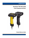
PowerScan® PBT7100 Cordless
Linear Imaging Barcode Reader
Product Reference Guide
Datalogic Scanning, Inc.
959 Terry Street
Eugene, Oregon 97402
Telephone: (541) 683-5700
Fax: (541) 345-7140
An Unpublished Work - All rights reserved. No part of the contents of this documentation or the procedures described
therein may be reproduced or transmitted in any form or by any means without prior written permission of Datalogic
Scanning, Inc. or its subsidiaries or affiliates ("Datalogic" or “Datalogic Scanning”). Owners of Datalogic products are
hereby granted a non-exclusive, revocable license to reproduce and transmit this documentation for the purchaser's own
internal business purposes. Purchaser shall not remove or alter any proprietary notices, including copyright notices, contained in this documentation and shall ensure that all notices appear on any reproductions of the documentation.
Should future revisions of this manual be published, you can acquire printed versions by contacting your Datalogic representative. Electronic versions may either be downloadable from the Datalogic website (www.scanning.datalogic.com) or
provided on appropriate media. If you visit our website and would like to make comments or suggestions about this or
other Datalogic publications, please let us know via the "Contact Datalogic" page.
Disclaimer
Datalogic has taken reasonable measures to provide information in this manual that is complete and accurate, however,
Datalogic reserves the right to change any specification at any time without prior notice.
Datalogic is a registered trademark of Datalogic S.p.A. in many countries and the Datalogic logo is a trademark of Datalogic S.p.A. All other brand and product names referred to herein may be trademarks of their respective owners.
This product may be covered by one or more of the following patents: 4603262 • 4639606 • 4652750 • 4672215 • 4699447 • 4709369 • 4749879 • 4786798
• 4792666 • 4794240 • 4798943 • 4799164 • 4820911 • 4845349 • 4861972 • 4861973 • 4866257 • 4868836 • 4879456 • 4939355 • 4939356 • 4943127 •
4963719 • 4971176 • 4971177 • 4991692 • 5001406 • 5015831 • 5019697 • 5019698 • 5086879 • 5115120 • 5144118 • 5146463 • 5179270 • 5198649 •
5200597 • 5202784 • 5208449 • 5210397 • 5212371 • 5212372 • 5214270 • 5229590 • 5231293 • 5232185 • 5233169 • 5235168 • 5237161 • 5237162 •
5239165 • 5247161 • 5256864 • 5258604 • 5258699 • 5260554 • 5274219 • 5296689 • 5298728 • 5311000 • 5327451 • 5329103 • 5330370 • 5347113 •
5347121 • 5371361 • 5382783 • 5386105 • 5389917 • 5410108 • 5420410 • 5422472 • 5426507 • 5438187 • 5440110 • 5440111 • 5446271 • 5446749 •
5448050 • 5463211 • 5475206 • 5475207 • 5479011 • 5481098 • 5491328 • 5493108 • 5504350 • 5508505 • 5512740 • 5541397 • 5552593 • 5557095 •
5563402 • 5565668 • 5576531 • 5581707 • 5594231 • 5594441 • 5598070 • 5602376 • 5608201 • 5608399 • 5612529 • 5629510 • 5635699 • 5641958 •
5646391 • 5661435 • 5664231 • 5666045 • 5671374 • 5675138 • 5682028 • 5686716 • 5696370 • 5703347 • 5705802 • 5714750 • 5717194 • 5723852 •
5750976 • 5767502 • 5770847 • 5786581 • 5786585 • 5787103 • 5789732 • 5796222 • 5804809 • 5814803 • 5814804 • 5821721 • 5822343 • 5825009 •
5834708 • 5834750 • 5837983 • 5837988 • 5852286 • 5864129 • 5869827 • 5874722 • 5883370 • 5905249 • 5907147 • 5923023 • 5925868 • 5929421 •
5945670 • 5959284 • 5962838 • 5979769 • 6000619 • 6006991 • 6012639 • 6016135 • 6024284 • 6041374 • 6042012 • 6045044 • 6047889 • 6047894 •
6056198 • 6065676 • 6069696 • 6073849 • 6073851 • 6094288 • 6112993 • 6129279 • 6129282 • 6134039 • 6142376 • 6152368 • 6152372 • 6155488 •
6166375 • 6169614 • 6173894 • 6176429 • 6188500 • 6189784 • 6213397 • 6223986 • 6230975 • 6230976 • 6244510 • 6259545 • 6260763 • 6266175 •
6273336 • 6276605 • 6279829 • 6290134 • 6290135 • 6293467 • 6303927 • 6311895 • 6318634 • 6328216 • 6332576 • 6332577 • 6343741 • 6454168 •
6478224 • 6568598 • 6578765 • 6705527 • 6857567 • 6974084 • 6991169 • 7051940 • 7170414 • 7172123 • 7201322 • 7204422 • 7215493 • 7224540 •
7234641 • 7243850 • 7374092 • 7407096 • 601 26 118.6 • AU703547 • D312631 • D313590 • D320011 • D320012 • D323492 • D330707 • D330708 • D349109
• D350127 • D350735 • D351149 • D351150 • D352936 • D352937 • D352938 • D352939 • D358588 • D361565 • D372234 • D374630 • D374869 • D375493 •
D376357 • D377345 • D377346 • D377347 • D377348 • D388075 • D446524 • EP0256296 • EP0260155 • EP0260156 • EP0295936 • EP0325469 • EP0349770 •
EP0368254 • EP0442215 • EP0498366 • EP0531645 • EP0663643 • EP0698251 • EP01330772 • GB2252333 • GB2284086 • GB2301691 • GB2304954 •
GB2307093 • GB2308267 • GB2308678 • GB2319103 • GB2333163 • GB2343079 • GB2344486 • GB2345568 • GB2354340 • ISR107546 • ISR118507 •
ISR118508 • JP1962823 • JP1971216 • JP2513442 • JP2732459 • JP2829331 • JP2953593 • JP2964278 • MEX185552 • MEX187245 • RE37166 • RE40.071 •
Other Patents Pending
Table of Contents
Chapter 1. Introduction ................................................................................................................................................................. 1
About this Guide ...............................................................................................................................................................................................................1
Manual Overview ..............................................................................................................................................................................................................1
Manual Conventions .......................................................................................................................................................................................................2
References ...........................................................................................................................................................................................................................2
Technical Support ............................................................................................................................................................................................................3
Datalogic Website Support .................................................................................................................................................................................3
Reseller Technical Support ..................................................................................................................................................................................3
Telephone Technical Support ............................................................................................................................................................................3
Chapter 2. Getting Started ............................................................................................................................................................ 5
About the Reader .............................................................................................................................................................................................................5
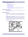
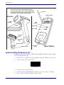
Unpacking ...........................................................................................................................................................................................................................5
Setting Up the Reader and Base Station ..................................................................................................................................................................6
Install the Battery in the Reader ........................................................................................................................................................................6
Connect the Base Station .....................................................................................................................................................................................6
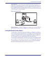
Linking the Reader to a Base Station ........................................................................................................................................................................7
Optional: Linking the Reader to a PC ........................................................................................................................................................................8
Paging Feature ..................................................................................................................................................................................................................9
Programming .....................................................................................................................................................................................................................9
Using the Programming Barcodes ...................................................................................................................................................................9
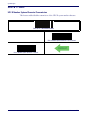
Select the Interface Type ......................................................................................................................................................................................9
Configure Interface Settings ...............................................................................................................................................................................9
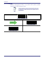
Configure Other Features ................................................................................................................................................................................. 10
Resetting the Standard Product Defaults ............................................................................................................................................................ 10
Chapter 3. Interfaces ................................................................................................................................................................... 11
Interface Selection ........................................................................................................................................................................................................ 11
Configuring the Interface ........................................................................................................................................................................................... 11
Global Interface Features ........................................................................................................................................................................................... 15
Host Commands — Obey/Ignore .................................................................................................................................................................. 15
USB Suspend Mode ............................................................................................................................................................................................. 16
Chapter 4. General Features....................................................................................................................................................... 17
Double Read Timeout .................................................................................................................................................................................................. 17
Label Gone Timeout ..................................................................................................................................................................................................... 19
Sleep Mode Timeout .................................................................................................................................................................................................... 21
LED and Beeper Indicators ......................................................................................................................................................................................... 23
Power On Alert ...................................................................................................................................................................................................... 23
Good Read: When to Indicate .......................................................................................................................................................................... 24
Good Read Beep Type ........................................................................................................................................................................................ 25
Good Read Beep Frequency ............................................................................................................................................................................ 26
Good Read Beep Length ................................................................................................................................................................................... 26
Good Read Beep Volume .................................................................................................................................................................................. 28
Good Read LED Duration .................................................................................................................................................................................. 29
Scanning Features ......................................................................................................................................................................................................... 31
Scan Mode .............................................................................................................................................................................................................. 31
Stand Mode Triggered Timeout ..................................................................................................................................................................... 33
Scanning Active Time ......................................................................................................................................................................................... 35
Flash On Time ................................................................................................................................................................................................................. 37
Flash Off Time ................................................................................................................................................................................................................. 39
Product Reference Guide
1
Stand Mode Sensitivity ................................................................................................................................................................................................41
Laser Pointer Control ....................................................................................................................................................................................................42
Laser Pointer Period ......................................................................................................................................................................................................43
Green Spot Duration .....................................................................................................................................................................................................45
Chapter 5. RS-232 ONLY Interface.............................................................................................................................................. 47
Introduction .....................................................................................................................................................................................................................47
RS-232 Standard Factory Settings ...........................................................................................................................................................................47
Baud Rate ..........................................................................................................................................................................................................................47
Data Bits .............................................................................................................................................................................................................................49
Stop Bits .............................................................................................................................................................................................................................50
Parity ...................................................................................................................................................................................................................................51
Handshaking Control ...................................................................................................................................................................................................52
Chapter 6. RS-232/USB-Com Interfaces ..................................................................................................................................... 53
Introduction .....................................................................................................................................................................................................................53
Standard Factory Settings ..........................................................................................................................................................................................53
Intercharacter Delay ......................................................................................................................................................................................................54
Beep On ASCII BEL .........................................................................................................................................................................................................56
Beep On Not on File ......................................................................................................................................................................................................56
ACK NAK Options ...........................................................................................................................................................................................................57
ACK Character ........................................................................................................................................................................................................58
NAK Character ........................................................................................................................................................................................................60
ACK NAK Timeout Value ....................................................................................................................................................................................62
ACK NAK Retry Count ..........................................................................................................................................................................................64
ACK NAK Error Handling ....................................................................................................................................................................................66
Indicate Transmission Failure ....................................................................................................................................................................................67
Disable Character ...........................................................................................................................................................................................................68
Enable Character ............................................................................................................................................................................................................70
Chapter 7. Keyboard Interface.................................................................................................................................................... 73
Introduction .....................................................................................................................................................................................................................73
Standard Factory Settings ..........................................................................................................................................................................................73
Scancode Tables .............................................................................................................................................................................................................73
Country Mode .................................................................................................................................................................................................................74
Caps Lock State ...............................................................................................................................................................................................................77
Numlock ............................................................................................................................................................................................................................77
Send Control Characters .............................................................................................................................................................................................78
Wedge Quiet Interval ...................................................................................................................................................................................................79
Intercharacter Delay ......................................................................................................................................................................................................81
Intercode Delay ...............................................................................................................................................................................................................83
USB Keyboard Speed ....................................................................................................................................................................................................85
Chapter 8. USB-OEM Interface .................................................................................................................................................... 87
Introduction .....................................................................................................................................................................................................................87
Standard Factory Settings ..........................................................................................................................................................................................87
USB-OEM Device Usage ...............................................................................................................................................................................................88
Chapter 9. IBM 46XX Interface.................................................................................................................................................... 89
Introduction .....................................................................................................................................................................................................................89
IBM Standard Factory Settings ..................................................................................................................................................................................89
46xx Number of Host Resets ......................................................................................................................................................................................90
Transmit Labels in Code 39 Format ........................................................................................................................................................................93
Chapter 10. Data Editing ............................................................................................................................................................. 95
Data Editing Overview .................................................................................................................................................................................................95
Please Keep In Mind... ...................................................................................................................................................................................................96
Global Prefix/Suffix ........................................................................................................................................................................................................96
2
PowerScan® PD7100 Corded
Example: Setting a Prefix ................................................................................................................................................................................... 96
Global AIM ID .................................................................................................................................................................................................................. 98
GS1-128 AIM ID .............................................................................................................................................................................................................100
Label ID ............................................................................................................................................................................................................................101
Label ID: Pre-loaded Sets .................................................................................................................................................................................101
Label ID: Set Individually Per Symbology .................................................................................................................................................103
Label ID Control ..................................................................................................................................................................................................105
Label ID Symbology Selection ......................................................................................................................................................................106
Case Conversion ..........................................................................................................................................................................................................112
Character Conversion ................................................................................................................................................................................................113
Chapter 11. Symbologies.......................................................................................................................................................... 115
Introduction ...................................................................................................................................................................................................................115
1D Symbologies ..................................................................................................................................................................................................115
Standard Factory Settings for Symbologies ......................................................................................................................................................115
Coupon Control ...........................................................................................................................................................................................................116
UPC-A ...............................................................................................................................................................................................................................117
UPC-A Enable/Disable ......................................................................................................................................................................................117
UPC-A Check Character Transmission ........................................................................................................................................................117
Expand UPC-A to EAN-13 ................................................................................................................................................................................118
UPC-A Number System Character Transmission ....................................................................................................................................118
In-Store Minimum Reads .................................................................................................................................................................................119
UPC-E ................................................................................................................................................................................................................................120
UPC-E Enable/Disable .......................................................................................................................................................................................120
UPC-E Check Character Transmission ........................................................................................................................................................120
Expand UPC-E to EAN-13 .................................................................................................................................................................................121
Expand UPC-E to UPC-A ...................................................................................................................................................................................121
UPC-E Number System Character Transmission ....................................................................................................................................122
UPC-E Minimum Reads ....................................................................................................................................................................................123
GTIN Formatting ..........................................................................................................................................................................................................124
EAN 13 ..............................................................................................................................................................................................................................125
EAN 13 Enable/Disable .....................................................................................................................................................................................125
EAN 13 Check Character Transmission ......................................................................................................................................................125
EAN-13 Flag 1 Character ..................................................................................................................................................................................126
EAN-13 ISBN Conversion .................................................................................................................................................................................127
EAN 13 Minimum Reads ..................................................................................................................................................................................128
EAN 8 ................................................................................................................................................................................................................................129
EAN 8 Enable/Disable .......................................................................................................................................................................................129
EAN 8 Check Character Transmission .........................................................................................................................................................129
Expand EAN 8 to EAN 13 .................................................................................................................................................................................130
EAN 8 Minimum Reads .....................................................................................................................................................................................131
UPC/EAN Global Settings .........................................................................................................................................................................................132
UPC/EAN Decoding Level ...............................................................................................................................................................................132
UPC/EAN Correlation ........................................................................................................................................................................................134
UPC/EAN Reconstruction ................................................................................................................................................................................134
UPC/EAN Price Weight Check ........................................................................................................................................................................135
UPC-A Minimum Reads ....................................................................................................................................................................................136
Add-Ons ..........................................................................................................................................................................................................................137
Optional Add-ons ...............................................................................................................................................................................................137
Optional Add-On Timer ...................................................................................................................................................................................139
Optional GS1-128 Add-On Timer .................................................................................................................................................................142
P2 Add-Ons Minimum Reads .........................................................................................................................................................................145
P5 Add-Ons Minimum Reads .........................................................................................................................................................................146
GS1-128 Add-Ons Minimum Reads .............................................................................................................................................................147
GS1 DataBar Omnidirectional .................................................................................................................................................................................148
GS1 DataBar Omnidirectional Enable/Disable ........................................................................................................................................148
GS1 DataBar Omnidirectional GS1-128 Emulation ...............................................................................................................................148
GS1 DataBar Omnidirectional Minimum Reads .....................................................................................................................................149
GS1 DataBar Expanded .............................................................................................................................................................................................150
Product Reference Guide
3
GS1 DataBar Expanded Enable/Disable .................................................................................................................................................... 150
GS1 DataBar Expanded GS1-128 Emulation ........................................................................................................................................... 150
GS1 DataBar Expanded Minimum Reads ................................................................................................................................................. 151
GS1 DataBar Expanded Length Control .................................................................................................................................................... 152
GS1 DataBar Expanded Set Length 1 ......................................................................................................................................................... 153
GS1 DataBar Expanded Set Length 2 ......................................................................................................................................................... 155
GS1 DataBar Limited .................................................................................................................................................................................................. 157
GS1 DataBar Limited Enable/Disable ......................................................................................................................................................... 157
GS1 DataBar Limited GS1-128 Emulation ................................................................................................................................................ 157
GS1 DataBar Limited Minimum Reads ....................................................................................................................................................... 158
Code 39 ........................................................................................................................................................................................................................... 159
Code 39 Enable/Disable .................................................................................................................................................................................. 159
Code 39 Check Character Calculation ....................................................................................................................................................... 160
Code 39 Check Character Transmission ................................................................................................................................................... 161
Code 39 Start/Stop Character Transmission ........................................................................................................................................... 161
Code 39 Full ASCII ............................................................................................................................................................................................. 162
Code 39 Quiet Zones ........................................................................................................................................................................................ 163
Code 39 Minimum Reads ................................................................................................................................................................................ 164
Code 39 Decoding Level ................................................................................................................................................................................. 165
Code 39 Length Control .................................................................................................................................................................................. 167
Code 39 Set Length 1 ....................................................................................................................................................................................... 168
Code 39 Set Length 2 ....................................................................................................................................................................................... 170
Code 39 Interdigit Ratio .................................................................................................................................................................................. 172
Code 39 Character Correlation ..................................................................................................................................................................... 174
Code 39 Stitching .............................................................................................................................................................................................. 175
Code 32 ........................................................................................................................................................................................................................... 176
Code 32 Enable/Disable .................................................................................................................................................................................. 176
Code 32 Feature Setting Exceptions .......................................................................................................................................................... 176
Code 32 Check Character Transmission ................................................................................................................................................... 177
Code 32 Start/Stop Character Transmission ........................................................................................................................................... 177
Code 128 ........................................................................................................................................................................................................................ 178
Code 128 Enable/Disable ............................................................................................................................................................................... 178
Expand Code 128 to Code 39 ...................................................................................................................................................................... 178
Code 128 Check Character Transmission ................................................................................................................................................. 179
Code 128 Function Character Transmission ........................................................................................................................................... 179
Code 128 Sub-Code Change Transmission ............................................................................................................................................. 180
Code 128 Quiet Zones ..................................................................................................................................................................................... 181
Code 128 Minimum Reads ............................................................................................................................................................................. 182
Code 128 Decoding Level .............................................................................................................................................................................. 183
Code 128 Length Control ............................................................................................................................................................................... 185
Code 128 Set Length 1 .................................................................................................................................................................................... 186
Code 128 Set Length 2 .................................................................................................................................................................................... 188
Code 128 Character Correlation .................................................................................................................................................................. 190
Code 128 Stitching ............................................................................................................................................................................................ 191
GS1-128 ........................................................................................................................................................................................................................... 192
GS1-128 Enable .................................................................................................................................................................................................. 192
Interleaved 2 of 5 (I 2 of 5) ....................................................................................................................................................................................... 193
I 2 of 5 Enable/Disable ..................................................................................................................................................................................... 193
I 2 of 5 Check Character Calculation ........................................................................................................................................................... 194
I 2 of 5 Check Character Transmission ....................................................................................................................................................... 195
I 2 of 5 Minimum Reads ................................................................................................................................................................................... 196
I 2 of 5 Decoding Level .................................................................................................................................................................................... 197
I 2 of 5 Length Control ..................................................................................................................................................................................... 199
I 2 of 5 Set Length 1 .......................................................................................................................................................................................... 200
I 2 of 5 Set Length 2 .......................................................................................................................................................................................... 202
I 2 of 5 Character Correlation ........................................................................................................................................................................ 204
I 2 of 5 Stitching .................................................................................................................................................................................................. 205
Datalogic 2 of 5 ............................................................................................................................................................................................................ 206
Datalogic 2 of 5 Enable/Disable ................................................................................................................................................................... 206
Datalogic 2 of 5 Check Character Calculation ........................................................................................................................................ 207
4
PowerScan® PD7100 Corded
Datalogic 2 of 5 Minimum Reads .................................................................................................................................................................208
Datalogic 2 of 5 Decoding Level ..................................................................................................................................................................208
Datalogic 2 of 5 Length Control ...................................................................................................................................................................209
Datalogic 2 of 5 Set Length 1 ........................................................................................................................................................................210
Datalogic 2 of 5 Set Length 2 ........................................................................................................................................................................212
Datalogic 2 of 5 Interdigit Maximum Ratio ..............................................................................................................................................214
Datalogic 2 of 5 Character Correlation ......................................................................................................................................................216
Datalogic 2 of 5 Stitching ................................................................................................................................................................................217
Codabar ...........................................................................................................................................................................................................................218
Codabar Enable/Disable ..................................................................................................................................................................................218
Codabar Check Character Calculation .......................................................................................................................................................219
Codabar Check Character Transmission ...................................................................................................................................................220
Codabar Start/Stop Character Transmission ...........................................................................................................................................220
Codabar Start/Stop Character Set ...............................................................................................................................................................221
Codabar Start/Stop Character Match .........................................................................................................................................................222
Codabar Quiet Zones ........................................................................................................................................................................................223
Codabar Minimum Reads ...............................................................................................................................................................................224
Codabar Decoding Level .................................................................................................................................................................................225
Codabar Length Control ..................................................................................................................................................................................227
Codabar Set Length 1 .......................................................................................................................................................................................228
Codabar Set Length 2 .......................................................................................................................................................................................230
Codabar Interdigit Ratio ..................................................................................................................................................................................232
Codabar Character Correlation .....................................................................................................................................................................234
Codabar Stitching ..............................................................................................................................................................................................235
Code 11 ...........................................................................................................................................................................................................................236
Code 11 Enable/Disable ..................................................................................................................................................................................236
Code 11 Check Character Calculation ........................................................................................................................................................237
Code 11 Check Character Transmission ....................................................................................................................................................238
Code 11 Minimum Reads ................................................................................................................................................................................239
Code 11 Length Control ..................................................................................................................................................................................240
Code 11 Set Length 1 .......................................................................................................................................................................................241
Code 11 Set Length 2 .......................................................................................................................................................................................243
Code 11 Interdigit Ratio ...................................................................................................................................................................................245
Code 11 Decoding Level .................................................................................................................................................................................247
Code 11 Character Correlation .....................................................................................................................................................................249
Code 11 Stitching ...............................................................................................................................................................................................250
Standard 2 of 5 .............................................................................................................................................................................................................251
Standard 2 of 5 Enable/Disable ....................................................................................................................................................................251
Standard 2 of 5 Check Character Calculation ..........................................................................................................................................252
Standard 2 of 5 Check Character Transmission ......................................................................................................................................252
Standard 2 of 5 Minimum Reads ..................................................................................................................................................................253
Standard 2 of 5 Decoding Level ...................................................................................................................................................................253
Standard 2 of 5 Length Control ....................................................................................................................................................................254
Standard 2 of 5 Set Length 1 .........................................................................................................................................................................255
Standard 2 of 5 Set Length 2 .........................................................................................................................................................................257
Standard 2 of 5 Character Correlation .......................................................................................................................................................259
Standard 2 of 5 Stitching .................................................................................................................................................................................260
ISBT 128 ...........................................................................................................................................................................................................................261
ISBT 128 Enable/Disable ..................................................................................................................................................................................261
ISBT 128 Concatenation ..................................................................................................................................................................................261
ISBT 128 Force Concatenation ......................................................................................................................................................................262
ISBT 128 Advanced Concatenation Options ............................................................................................................................................262
Code 4 ..............................................................................................................................................................................................................................263
Code 4 Enable/Disable .....................................................................................................................................................................................263
Code 4 Check Character Transmission .......................................................................................................................................................264
Code 4 Hex to Decimal Conversion ............................................................................................................................................................264
Code 5 ..............................................................................................................................................................................................................................265
Code 5 Enable/Disable .....................................................................................................................................................................................265
Code 5 Check Character Transmission .......................................................................................................................................................266
Code 5 Hex to Decimal Conversion ............................................................................................................................................................266
Product Reference Guide
5
Code 4 and Code 5 Common Configuration Items ........................................................................................................................................ 267
Code 4 and 5 Decoding Level ....................................................................................................................................................................... 267
Code 4 and Code 5 Minimum Reads .......................................................................................................................................................... 269
Follett 2 of 5 .................................................................................................................................................................................................................. 270
Follett 2 of 5 Enable/Disable ......................................................................................................................................................................... 270
Chapter 12. BT Features ............................................................................................................................................................ 273
Introduction .................................................................................................................................................................................................................. 273
Standard Factory Settings ....................................................................................................................................................................................... 273
BT Beeper Features ..................................................................................................................................................................................................... 274
ACK Beep .............................................................................................................................................................................................................. 274
Beep Frequency ................................................................................................................................................................................................. 275
Beep Duration ..................................................................................................................................................................................................... 276
Beep Volume ....................................................................................................................................................................................................... 278
BT Base Station Beep ........................................................................................................................................................................................ 279
Disconnect Beep ................................................................................................................................................................................................ 279
BT Leash Alarm ................................................................................................................................................................................................... 280
Flash Update ................................................................................................................................................................................................................. 282
BT Automatic Flash Update ........................................................................................................................................................................... 282
Request Flash Update ...................................................................................................................................................................................... 282
Configuration Update ............................................................................................................................................................................................... 283
Automatic Configuration Update ............................................................................................................................................................... 283
Configuration Update From Base Station to Handheld ...................................................................................................................... 283
Copy Configuration From Handheld to Base Station .......................................................................................................................... 284
Battery Charge Mode ................................................................................................................................................................................................. 285
Powerdown Timeout ................................................................................................................................................................................................. 286
BT Poll Rate .................................................................................................................................................................................................................... 288
Batch Features .............................................................................................................................................................................................................. 290
Batch Mode .......................................................................................................................................................................................................... 290
Send Batch ........................................................................................................................................................................................................... 291
Erase Batch Memory ......................................................................................................................................................................................... 291
BT Security Features ................................................................................................................................................................................................... 291
BT Pin Code .......................................................................................................................................................................................................... 291
BT Security Mode ............................................................................................................................................................................................... 294
BT SPP Mode ................................................................................................................................................................................................................. 295
BT Address Stamping ................................................................................................................................................................................................ 296
Source Radio Address Transmission .......................................................................................................................................................... 296
Source Radio Address Delimiter Character ............................................................................................................................................. 297
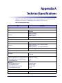
Appendix A. Technical Specifications ..................................................................................... 299
Standard Cable Pinouts ............................................................................................................................................................................................ 302
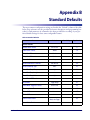
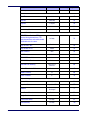
Appendix B. Standard Defaults .............................................................................................. 303
Appendix C. LED and Beeper Indications ............................................................................... 313
General Functions — LED and Beeper Indications ........................................................................................................................................ 314
BT Beeper Indications ................................................................................................................................................................................................ 315
BT LED Indications ...................................................................................................................................................................................................... 316
Error Codes .................................................................................................................................................................................................................... 317
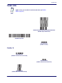
Appendix D. Sample Barcodes ............................................................................................... 319
UPC-A ................................................................................................................................................................................................................ 319
Interleaved 2 of 5 .................................................................................................................................................................................................... 319
Codabar ..................................................................................................................................................................................................................... 320
Code 11 ...................................................................................................................................................................................................................... 320
DataBar (RSS) ................................................................................................................................................................................................................ 321
DataBar-14 ............................................................................................................................................................................................................ 321
6
PowerScan® PD7100 Corded
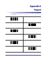
Appendix E. Keypad ............................................................................................................... 323
Appendix F. Scancode Tables ................................................................................................. 327
Control Character Emulation ..................................................................................................................................................................................327
Single Press and Release Keys .......................................................................................................................................................................327
Interface Type PC AT PS/2 or USB-Keyboard ....................................................................................................................................................328
Interface type PC AT PS/2 Alt Mode or USB-Keyboard Alt Mode ..............................................................................................................330
Digital Interface ............................................................................................................................................................................................................332
IBM31xx 102-key .........................................................................................................................................................................................................334
IBM XT ..............................................................................................................................................................................................................................336
Microsoft Windows Codepage 1252 ....................................................................................................................................................................338
Index ..................................................................................................................... 339
Product Reference Guide
7
NOTES
8
PowerScan® PD7100 Corded
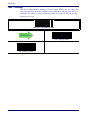
Chapter 1
Introduction
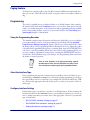
About this Guide
This Product Reference Guide (PRG) is provided for users seeking advanced technical
information, including connection, programming, maintenance and specifications. The
Quick Reference Guide (QRG) and other publications associated with this product are
downloadable free of charge from the website listed on the back cover of this manual.
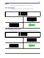
Typically, units are factory-programmed for the most common terminal and communications settings. If you need to modify any programmable settings, custom configuration
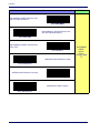
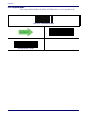
can be accomplished by scanning the programming barcodes within this guide.
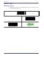
Programming can alternatively be performed using the Datalogic Aladdin™ Configuration application which is downloadable from the Datalogic website listed on the back
cover of this manual. This multi-platform utility program allows device configuration using a PC. It communicates to the device using a serial or USB cable and can also create
configuration barcodes to print.
Manual Overview
Chapter 1, Introduction provides a product overview, unpacking instructions, and cable
connection information.
Chapter 2, Getting Started presents information about unpacking and setting up the
reader.
Chapter 3, Interfaces consists of interface configuration barcodes and details.
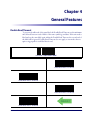
Chapter 4, General Features includes programming barcodes for selecting common
features for the reader and general use barcodes to customize how the data is transmitted
to the host device.
Chapter 5, RS-232 ONLY Interface supplies information about setting up the reader for
RS-232 operation.
Chapter 6, RS-232/USB-Com Interfaces features information about options involving
both the RS-232 and USB-Com interfaces.
Chapter 7, Keyboard Interface discusses how to set up the reader for Keyboard Wedge
operation.
Chapter 8, USB-OEM Interface explains how to set the reader up for USB operation.
Chapter 9, IBM 46XX Interface is a resource for setting up an IBM interface.
Chapter 10, Data Editing offers advanced configuration options for customization of
scanned data output.
Product Reference Guide
1
Introduction
Chapter 11, Symbologies defines options for all symbologies and provides the program-
ming barcodes necessary for configuring these features.
Appendix A, Technical Specifications lists physical and performance characteristics, as
well as environmental and regulatory specifications. It also provides standard cable pinouts.
Appendix B, Standard Defaults references common factory default settings for reader
features and options.
Appendix C, LED and Beeper Indications supplies tables containing descriptions of the
functions and behaviors of the reader’s LED and Beeper indicators.
Appendix D, Sample Barcodes offers sample barcodes of several common symbologies.
Appendix E, Keypad includes numeric barcodes to be scanned for certain parameter settings.
Appendix F, Scancode Tables lists control character emulation information for Wedge
and USB Keyboard interfaces.
Manual Conventions
The following conventions are used in this document:
The symbols listed below are used in this manual to notify the reader of key issues or
procedures that must be observed when using the reader:
Notes contain information necessary for properly diagnosing, repairing and operating the reader.
NOTE
The CAUTION symbol advises you of actions that could damage
equipment or property.
CAUTION
References
Current versions of the Product Reference Guide (PRG), Quick Reference Guide
(QRG), the Datalogic Aladdin™ Configuration application, and any other manuals, instruction sheets and utilities for this product can be downloaded from the website listed
on the back cover of this manual. Alternatively, printed copies or product support CDs
can be purchased through your Datalogic reseller.
2
PowerScan® PBT7100 Cordless
Technical Support
Technical Support
Datalogic Website Support
The Datalogic website (www.scanning.datalogic.com) is the complete source for technical
support and information for Datalogic products. The site offers product support, product registration, warranty information, product manuals, product tech notes, software
updates, demos, and instructions for returning products for repair.
Reseller Technical Support
An excellent source for technical assistance and information is an authorized Datalogic
reseller. A reseller is acquainted with specific types of businesses, application software,
and computer systems and can provide individualized assistance.
Telephone Technical Support
If you do not have internet or email access, you may contact Datalogic technical support
at (541) 349-8283 or check the back cover of your manual for more contact information.
Product Reference Guide
3
Introduction
NOTES
4
PowerScan® PBT7100 Cordless
Chapter 2
Getting Started
About the Reader
Advancements in the LED technology used in this reader significantly improve the illumination of the target field of view, resulting in higher scan efficiency. Whether used in
Single Trigger or Continuous Mode, the ergonomic design of the reader will help to promote comfortable handling during extended periods of use.
The reader/Base Station can communicate using the following interfaces:
RS-232 —
The reader can communicate with a standard or Wincor-Nixdorf (W-N) RS-
232 host.
RS-232 OPOS —
This interface is used for OPOS/UPOS/JavaPOS systems.
Keyboard Wedge (KBW) —
When connected using this interface, the host interprets
scanned data as keystrokes and supports several international keyboards (for the Windows® environment). See Country Mode on page 74 for a full listing.
USB — Select to communicate either by USB OEM, USB COM, USB Keyboard interface or USB POS types by scanning the appropriate interface type barcodes available in
this manual. The default interface is USB-KBD for Wedge models (7230) and USBOEM for IBM models (7210).
IBM —
IBM Port 5B or Port 9B are selectable interface options.
Unpacking
Check carefully to ensure the reader, Base Station and any accessories ordered are present
and undamaged. If any damage occurred during shipment, contact Technical
Support on page 3.
KEEP THE PACKAGING. Should the unit ever require service, it should be returned
in its original shipping container.
Product Reference Guide
5
Getting Started
Setting Up the Reader and Base Station
Follow the steps provided in this section to connect and get your reader up and communicating with its host:
1. Install the Battery in the Reader
2. Connect the Base Station
3. Select the Interface Type
4. Configure Interface Settings (only if not using factory settings for that interface)
5. Configure Other Features (if modifications are needed from factory settings)
Install the Battery in the Reader
Follow the instructions in the Quick Reference Guide (QRG) to install the battery pack
and verify reader operation.
Connect the Base Station
Figure 1 shows how to connect the Base Station to a terminal, PC or other host device.
Turn off the host before connection and consult the manual for that equipment (if necessary) before proceeding. Connect the interface cable before applying power to the Base
Station.
Base Station Connection and Routing —
Fully insert the Power Cable and Interface
(I/F) Cable connectors into their respective ports in the underside of the Base Station (see
Figure 1), then plug the Base Station AC Adapter into the AC outlet. Alternatively, you
can either loop the cables around the routing clips and back through the routing channel
to the front of the Base Station as shown, or the cables can be fed directly out the back
of the Base Station via the routing clips.
Figure 1. Connecting the Base Station
Power Cable
I/F
Cable
Routing
Channel
Routing
Clips
Bottom of Base Station
I/F Cable
AC
Adapter
Base
Station
6
Power Cable
PowerScan® PBT7100 Cordless
Linking the Reader to a Base Station
Host Connection —
The interface type was specified at the time your reader was ordered, however you should verify before connection that the reader’s cable type is compatible with your host equipment. Most connections plug directly into the host device as
shown in Figure 2. Keyboard Wedge interface cables have a ‘Y’ connection where its female end mates with the male end of the cable from the keyboard and the remaining end
at the keyboard port on the terminal/PC.
B
Figure 2. Connecting to the Host
Wa
Ke W
or...
nd
US
yb
ed oard
ge
or...
M
or...
IB
Power Connection —
Plug the AC Adapter in to an approved AC wall socket with the
cable facing downwards (as shown in Figure 1) to prevent undue strain on the socket.
Linking the Reader to a Base Station
To link a reader to a Base Station, press the Link Button (see Figure 3) on the Base Station for at least one second to place the base in "Link Mode," then scan the barcode below or the Link barcode located on the Base Station using the reader to be linked. The
Link barcode on the Base Station contains an identifier that is unique to that Base Station. This enables the reader to quickly find and link to that Base Station.
A successful link is indicated by three ascending tones from the reader. A high-low-highlow tone indicates the link attempt was unsuccessful. A single green LED flash during
this tone indicates no Base Station was discovered. Two green LED flashes during this
tone indicates that more than one Base Station was discovered and the reader did not
link. Three LED flashes during this tone indicate a security error.
Product Reference Guide
7
Getting Started
Figure 3. Labeling and Nomenclature
This illustration shows label placement ONLY.
For actual regulatory, patent and other applicable
information, view the labels on the product intself,
or call your nearest sales or service office.
Antenna
Link Bar Code
Scanner
Scan
Window
Link
Button
Trigger
Amber LED
Green LED
S/N and Laser Safety Label
Indicator
LEDs
Speaker
Port
Battery Pack
Battery Latch
Scanner
Latch
Base Station
Optional: Linking the Reader to a PC
A reader can optionally be linked to a Bluetooth-enabled PC with the serial port profile.
To do this, follow these steps:
1. Ensure the PC or terminal can network with Bluetooth devices and that it is powered on.
2. Scan the “Link to a PC” barcode below.
Link to a PC
3. On the PC, scan for network devices.
4. Select the “Datalogic PBT7100 Reader.” Make sure “Secure Connection” is disabled.
5. Select “connect” on the PC to link the reader to the PC.
8
PowerScan® PBT7100 Cordless
Paging Feature
Paging Feature
To help locate a missing reader, press the Base Station Link Button momentarily (less
than one second). This will cause the reader to beep five times at its loudest volume setting.
Programming
The reader is typically factory-configured with a set of default features. After scanning
the interface barcode from the Interfaces section, you can select other options and customize your reader through use of the instructions and programming barcodes available
in the corresponding features section for your interface and also the Data Editing and
Symbologies chapters of this manual.
Using the Programming Barcodes
This manual contains feature descriptions and barcodes which allow you to reconfigure
your reader and Base Station. Some programming barcode labels, like the Standard
Product Default Settings on page 10, require only the scan of that single label to enact
the change. Most of the programming labels in this manual, however, require the reader
to be placed in Programming Mode prior to scanning them. Scan an ENTER/EXIT barcode once to enter Programming Mode. Once the reader is in Programming Mode, you
can scan a number of parameter settings before scanning the ENTER/EXIT barcode a
second time, which will then accept your changes, exit Programming Mode and return
the reader to normal operation.
There are some exceptions to the typical programming sequence
described above. Please read the description and setting instructions carefully when configuring each given programmable feature.
NOTE
Select the Interface Type
Upon completing the physical connection between the Base Station and the host, proceed directly to Interfaces on page 11 for information and programming for the interface type the Base Station is connected to (for example: RS-232, Keyboard Wedge, USB,
etc.) and scan the appropriate barcode in that section to select your system’s correct interface type.
Configure Interface Settings
Each interface type is associated to a specific set of default features. If after scanning the
interface barcode from the Interfaces section, your installation requires you to select options to further customize your reader, turn to the appropriate section for your interface
type as listed below:
•
RS-232 ONLY Interface, starting on page 47
•
RS-232/USB-Com Interfaces, starting on page 53
•
Keyboard Interface, starting on page 73
Product Reference Guide
9
Getting Started
•
USB-OEM Interface, starting on page 87
•
IBM 46XX Interface, starting on page 89
Configure Other Features
If your installation requires different programming than the standard factory default settings, the following sections of this manual allow configuration of non-interface-specific
settings you might require:
General Features — General Features includes programming for scanning, beeper and
LED indicators and other such universal settings.
Symbologies — Includes options concerning the barcode label types (symbologies).
These settings allow you to enable/disable symbologies, set label lengths, require check
digit, etc.
Resetting the Standard Product Defaults
If you aren’t sure what programming options are in your reader, or you’ve changed some
options and want the factory settings restored, scan the Standard Product Default Settings barcode below. This will copy the factory configuration for the currently active interface to the current configuration.
Factory defaults are based on the interface type. Configure the
reader for the correct interface before scanning this label.
NOTE
Standard Product Default Settings
The programming section lists the factory default settings for each of the menu commands (indicated by shaded blocks and bold text) on the following pages.
10
PowerScan® PBT7100 Cordless
Chapter 3
Interfaces
Interface Selection
Each reader model will support one of the following sets of host interfaces:
General Purpose Models (5 volt supply)
RS-232
RS-232 OPOS
USB
Keyboard Wedge
Retail Point of Sale Models (4 to 14 volt supply)
RS-232
RS-232 OPOS
USB
IBM 46XX
Configuring the Interface
Scan the programming barcode from this section which selects the appropriate interface
type matching the system the reader will be connected to. Next, proceed to the corresponding chapter in this manual (also listed in Table 1) to configure any desired settings
and features associated with that interface.
Unlike some other programming features and options, interface
selections require that you scan only one programming barcode
label. DO NOT scan an ENTER/EXIT barcode prior to scanning an
interface selection barcode.
NOTE
Product Reference Guide
Some interfaces require the scanner to start in the disabled state
when powered up. If additional scanner configuration is desired
while in this state, pull the trigger and hold it for five seconds. The
scanner will change to a state that allows programming with barcodes.
11
Interfaces
Table 1. Available Interfaces
RS-232
FEATURES
RS-232 standard interface
Select RS232-STD
RS-232 Wincor-Nixdorf
Set RS-232
Interface
Features
Select RS232-WN
starting on
page 47
RS-232 for use with OPOS/UPOS/JavaPOS
Select RS-232 OPOS
USB Com to simulate RS-232 standard interface
Select USB-COM-STDa
IBM
FEATURES
IBM-46xx Port 5B reader interface
Set IBM
Interface
Features
Select IBM-P5B
starting on
page 89
IBM-46xx Port 9B reader interface
Select IBM-P9B
USB-OEM
FEATURES
USB-OEM
(can be used for OPOS/UPOS/JavaPOS)
Select USB-OEM
a.
12
Set USB-OEM
Interface
Features
starting on
page 87
Download the correct USB Com driver from www.datalogic.com
PowerScan® PBT7100 Cordless
Configuring the Interface
KEYBOARD
FEATURES
AT, PS/2 25-286, 30-286, 50, 50Z, 60, 70, 80, 90 & 95
w/Standard Key Encoding
Select KBD-AT
Keyboard Wedge for IBM AT PS2 with standard key
encoding but without external keyboard
Select KBD-AT-NK
AT, PS/2 25-286, 30-286, 50, 50Z, 60, 70, 80, 90 & 95
w/Alternate Key
Select KBD-AT-ALT
Keyboard Wedge for IBM AT PS2 with alternate key
encoding but without external keyboard
Set KEYBOARD
WEDGE
Interface
Features
starting on page
73
Select KBD-AT-ALT-NK
PC/XT w/Standard Key Encoding
Select KBD-XT
Keyboard Wedge for IBM Terminal 3153
Select KBD-IBM-3153
Product Reference Guide
13
Interfaces
KEYBOARD — cont.
FEATURES
Keyboard Wedge for IBM Terminals 31xx, 32xx,
34xx, 37xx make only keyboard
Select KBD-IBM-M
Keyboard Wedge for IBM Terminals 31xx, 32xx,
34xx, 37xx make break keyboard
Select KBD-IBM-MB
Keyboard Wedge for DIGITAL Terminals VT2xx,
VT3xx, VT4xx
Set KEYBOARD
WEDGE
Interface
Features
Select KBD-DIG-VT
USB Keyboard with standard key encoding
starting on page
73
Select USB Keyboard
USB Keyboard with alternate key encoding
Select USB Alternate Keyboard
USB Keyboard for Apple computers
Select USB-KBD-APPLE
14
PowerScan® PBT7100 Cordless
Global Interface Features
Global Interface Features
The following interface features are configurable by all interface types. To set features
specific to your interface, turn to that section of this manual:
•
RS-232 ONLY Interface on page 47
•
Keyboard Interface on page 73
•
USB-OEM Interface on page 87
•
IBM 46XX Interface on page 89
Host Commands — Obey/Ignore
This option specifies whether the reader will obey or ignore host commands. When set
to ignore, the reader will ignore all host commands except for those necessary for:
•
service mode
•
flash programming mode
•
keeping the interface active
•
transmission of labels.
ENTER/EXIT PROGRAMMING MODE
DEFAULT
Host Commands = Obey
Host Commands = Ignore
Product Reference Guide
15
Interfaces
USB Suspend Mode
This setting enables/disables the ability of USB interfaces to enter suspend mode.
ENTER/EXIT PROGRAMMING MODE
DEFAULT
USB Suspend Mode = Disable
USB Suspend Mode = Enable
16
PowerScan® PBT7100 Cordless
Chapter 4
General Features
Double Read Timeout
To prevent a double read of the same label, the Double Read Timeout sets the minimum
time allowed between reads of labels of the same symbology and data. If the unit reads a
label and sees the same label again within the Double Read Timeout, the second read of
the label will be ignored. Double Read Timeout does not apply to scan modes that require a trigger pull for each label that is read.
ENTER/EXIT PROGRAMMING MODE
Double Read Timeout = 0.1 Second
Double Read Timeout = 0.2 Second
Double Read Timeout = 0.3 Second
DEFAULT
Double Read Timeout = 0.4 Second
Product Reference Guide
17
General Features
Double Read Timeout — continued
ENTER/EXIT PROGRAMMING MODE
Double Read Timeout = 0.5 Second
Double Read Timeout = 0.6 Second
Double Read Timeout = 0.7 Second
Double Read Timeout = 0.8 Second
Double Read Timeout = 0.9 Second
Double Read Timeout = 1 Second
18
PowerScan® PBT7100 Cordless
Label Gone Timeout
Label Gone Timeout
This feature sets the time after the last label segment is seen before the reader prepares for
a new label. The timeout can be set within a range of 10 milliseconds to 2,550 milliseconds (2.55 seconds) in 10ms increments.
Follow these instructions to set this feature:
1. Determine the desired setting in milliseconds.
2. Divide the desired setting by 10 (setting is in 10ms increments). Pad the result with leading zeroes to yield three digits. For example: 0 = 000, 5 = 005, 20 = 020, etc.
3. Scan the ENTER/EXIT PROGRAMMING MODE barcode to enter Programming
Mode.
4. Scan the barcode: SELECT LABEL GONE TIMEOUT SETTING.
5. Scan the appropriate three alpha-numeric characters from the keypad in Appendix E, Keypad representing the duration which was determined in the steps above. You will hear a
two-beep indication after the last character.
If you make a mistake before the last character, scan the CANCEL barcode to
abort and not save the entry string. You can then start again at the beginning.
NOTE
6. Scan the ENTER/EXIT PROGRAMMING MODE barcode to exit Programming
Mode.
This completes the procedure. See Table 2 for some examples of how to set this feature.
Table 2. Timeout Setting Examples
STEP
ACTION
EXAMPLES
1
Desired Setting
2
Divide by 10 (and pad with leading
zeroes)
3
Scan ENTER/EXIT PROGRAMMING MODE
4
Scan SELECT LABEL GONE TIMEOUT SETTING
5
6
Scan Three Characters From
Appendix E, Keypad
50ms
150ms
1800ms (1.8 sec.)
2550ms (2.55 sec.)
005
015
180
255
‘0’, ‘1’ and ‘5’
‘1’, ‘8’ and ‘0’
‘‘2’, ‘5’ and ‘5’
‘0’, ‘0’ and ‘5’
Scan ENTER/EXIT PROGRAMMING MODE
Product Reference Guide
19
General Features
Label Gone Timeout — cont.
ENTER/EXIT PROGRAMMING MODE
Select Label Gone Timeout Setting
Make a mistake? Scan the CANCEL barcode to abort and not
save the entry string. You can then start again at the beginning.
CANCEL
DEFAULT
20
016 = Timeout of 160 ms
PowerScan® PBT7100 Cordless
Sleep Mode Timeout
Sleep Mode Timeout
Specifies the timeout value for the reader to enter low power Sleep Mode.
ENTER/EXIT PROGRAMMING MODE
DEFAULT
Sleep Mode Timeout = Disable
Sleep Mode Timeout = 500ms
Sleep Mode Timeout = 1 Second
Sleep Mode Timeout = 2 Seconds
Sleep Mode Timeout = 3 Seconds
Sleep Mode Timeout = 4 Seconds
Product Reference Guide
21
General Features
Sleep Mode Timeout — continued
ENTER/EXIT PROGRAMMING MODE
Sleep Mode Timeout = 5 Seconds
Sleep Mode Timeout = 6 Seconds
Sleep Mode Timeout = 7 Seconds
Sleep Mode Timeout = 8 Seconds
Sleep Mode Timeout = 9 Seconds
Sleep Mode Timeout = 9.9 Seconds (9,900ms max.)
22
PowerScan® PBT7100 Cordless
LED and Beeper Indicators
LED and Beeper Indicators
Power On Alert
Disables or enables the indication (from the Beeper) that the reader is receiving power.
ENTER/EXIT PROGRAMMING MODE
Power On Alert = Disable (No Audible Indication)
DEFAULT
Power On Alert = Four Beeps
Product Reference Guide
23
General Features
Good Read: When to Indicate
This feature specifies when the reader will provide indication (beep and/or flash its green
LED) upon successfully reading a barcode. Choices are:
•
Good Read = Indicate after decode
•
Good Read = Indicate after transmit
•
Good Read = Indicate after CTS goes inactive, then active
This option, which uses CTS, is only valid for RS-232
interfaces.
NOTE
ENTER/EXIT PROGRAMMING MODE
DEFAULT
Indicate Good Read = After Decode
Indicate Good Read = After Transmit
Indicate Good Read = After CTS Goes Inactive, Then Active
24
PowerScan® PBT7100 Cordless
LED and Beeper Indicators
Good Read Beep Type
Specifies whether the good read beep has a mono or bitonal beep sound.
ENTER/EXIT PROGRAMMING MODE
DEFAULT
Good Read Beep Type = Mono
Good Read Beep Type = Bitonal
Product Reference Guide
25
General Features
Good Read Beep Frequency
Adjusts the good read beep to sound at a selectable low, medium or high frequency, selectable from the list below. (Controls the beeper’s pitch/tone.)
ENTER/EXIT PROGRAMMING MODE
Good Read Beep Frequency = Low
Good Read Beep Frequency = Medium
DEFAULT
Good Read Beep Frequency = High
Good Read Beep Length
Specifies the duration of a good read beep.
ENTER/EXIT PROGRAMMING MODE
Good Read Beep Length = 60 msec
26
PowerScan® PBT7100 Cordless
LED and Beeper Indicators
Good Read Beep Length — continued
ENTER/EXIT PROGRAMMING MODE
DEFAULT
Good Read Beep Length = 80 msec
Good Read Beep Length = 100 msec
Good Read Beep Length = 120 msec
Good Read Beep Length = 140 msec
Good Read Beep Length = 160 msec
Good Read Beep Length = 180 msec
Good Read Beep Length = 200 msec
Product Reference Guide
27
General Features
Good Read Beep Volume
Selects the beeper volume (loudness) upon a good read beep. There are three selectable
volume levels.
ENTER/EXIT PROGRAMMING MODE
Good Read Beep Volume = Beeper Off
Good Read Beep Volume = Low
Good Read Beep Volume = Medium
DEFAULT
Good Read Beep Volume = High
28
PowerScan® PBT7100 Cordless
LED and Beeper Indicators
Good Read LED Duration
This feature specifies the amount of time that the Good Read LED remains on following
a good read. The good read LED on time can be set within a range of 10 milliseconds to
2,550 milliseconds (0.001 to 2.55 seconds) in 10ms increments.
Follow these instructions to set this feature:
1. Determine the desired setting in milliseconds. A setting of 0 means that the good read
LED stays on until the next time the trigger is pulled.
2. Divide the desired setting by 10 (setting is in 10ms increments). Pad the result with leading zeroes to yield three digits. For example: 0 = 000, 5 = 000, 20 = 020, etc.
3. Scan the ENTER/EXIT PROGRAMMING MODE barcode to enter Programming
Mode.
4. Scan the barcode: SELECT GOOD READ LED DURATION SETTING.
5. Scan the appropriate three digits from the keypad in Appendix E, Keypad representing the
duration which was determined in the steps above. You will hear a two-beep indication
after the last character.
If you make a mistake before the last character, scan the CANCEL barcode to
abort and not save the entry string. You can then start again at the beginning.
NOTE
6. Scan the ENTER/EXIT PROGRAMMING MODE barcode to exit Programming
Mode.
This completes the procedure. See Table 3 for some examples of how to set this feature.
Table 3. Good Read LED Duration Setting Examples
STEP
ACTION
EXAMPLES
Good Read LED
stays on until next
trigger pull (00)
20ms
150ms
2550ms (2.55 sec.)
000
002
015
255
‘0’, ‘0’ and ‘2’
‘0’, ‘1’ and ‘5’
‘2’, ‘5’ and ‘5’
1
Desired Setting
2
Divide by 10 (and pad with leading
zeroes)
3
Scan ENTER/EXIT PROGRAMMING MODE
4
Scan SELECT LABEL GONE TIMEOUT SETTING
5
6
Scan Three Characters From
Appendix E, Keypad
‘0’, ‘0’ and ‘0’
Scan ENTER/EXIT PROGRAMMING MODE
Product Reference Guide
29
General Features
Good Read LED Duration — cont.
ENTER/EXIT PROGRAMMING MODE
Select Good Read LED Duration Setting
Make a mistake? Scan the CANCEL barcode to abort and not
save the entry string. You can then start again at the beginning.
CANCEL
DEFAULT
020 = Good Read LED stays on for
2 seconds.
Indicators are dimmed during sleep.
NOTE
30
PowerScan® PBT7100 Cordless
Scanning Features
Scanning Features
Scan Mode
Selects the scan operating mode for the reader. Selections are:
Trigger Single —
When the trigger is pulled, scanning is activated until one of the fol-
lowing occurs:
- Scanning Active Time has elapsed
- a label has been read
- the trigger is released
This mode is associated with typical handheld reader operation: when the trigger is
pulled, scanning starts and the product scans until the trigger is released, or a label is read,
or the maximum Scanning Active Time has elapsed.
Trigger Hold Multiple —
When the trigger is pulled, scanning starts and the product
scans until the trigger is released or Scanning Active Time has elapsed. Reading a label does
not disable scanning. Double Read Timeout prevents undesired multiple reads of the same
label while in this mode.
Trigger Pulse Multiple —
When the trigger is pulled, continuous scanning is activated
until Scanning Active Time has elapsed or the trigger has been released and pulled again.
Double Read Timeout1 prevents undesired multiple reads of the same label while in this
mode.
The reader flashes1 on and off regardless of the trigger status. Flash rate is
controlled by Flash On Time and Flash Off Time.
Flashing —
Always On —
No trigger pull is required to read a barcode. Scanning is continually on.
If the trigger is pulled, the reader acts as if it is in Trigger Single Mode. Double Read
Timeout1 prevents undesired multiple reads of the same label while in this mode.
Stand Mode — No trigger pull is required to read a barcode. Scanning is turned on automatically when an item is placed in reader’s field of view. If the trigger is pulled, the
reader acts as if it in single read mode. Double Read Timeout1 prevents undesired multiple
reads of the same label while in this mode.
Trigger Object Sense —
This mode is similar to Stand Mode, except that a trigger pull
is required to activate the decoder.
1. Controlled by Flash On Time.
Product Reference Guide
31
General Features
Scan Mode — continued
ENTER/EXIT PROGRAMMING MODE
DEFAULT
Scan Mode = Trigger Single
Scan Mode = Trigger Hold Multiple
Scan Mode = Trigger Pulse Multiple
Scan Mode = Flashing
Scan Mode = Always On
Scan Mode = Stand Mode
Scan Mode = Trigger Object Sense
32
PowerScan® PBT7100 Cordless
Scanning Features
Stand Mode Triggered Timeout
This feature specifies the time to remain in Trigger Single mode after the trigger is pulled
while in Stand Mode.
This timeout is only used when the Scan Mode is configured as
Stand
Mode.
NOTE
ENTER/EXIT PROGRAMMING MODE
DEFAULT
Stand Mode Triggered Timeout = 0.5 Seconds
Stand Mode Triggered Timeout = 1.5 Seconds
Stand Mode Triggered Timeout = 2 Seconds
Stand Mode Triggered Timeout = 3 Seconds
Stand Mode Triggered Timeout = 4 Seconds
Product Reference Guide
33
General Features
Stand Mode Triggered Timeout — continued
ENTER/EXIT PROGRAMMING MODE
Stand Mode Triggered Timeout = 6 Seconds
Stand Mode Triggered Timeout = 8 Seconds
Stand Mode Triggered Timeout = Switch back to Trigger Single
on trigger pull
34
PowerScan® PBT7100 Cordless
Scanning Features
Scanning Active Time
This setting specifies the amount of time that the reader stays in scan ON state once the
state is entered. The range for this setting is from 1 to 255 seconds in 1-second increments.
Follow these instructions to set this feature:
1. Determine the desired setting.
2. Pad the result with leading zeroes to yield three digits. For example: 0 = 000, 5 = 005, 20
= 020, etc.
3. Scan the ENTER/EXIT PROGRAMMING MODE barcode to enter Programming
Mode.
4. Scan the barcode: SELECT SCANNING ACTIVE TIME SETTING.
5. Scan the appropriate three digits from the keypad in Appendix E, Keypad, that represent
the duration which was determined in the steps above. You will hear a two-beep indication after the last character.
If you make a mistake before the last character, scan the CANCEL barcode to
abort and not save the entry string. You can then start again at the beginning.
NOTE
6. Scan the ENTER/EXIT PROGRAMMING MODE barcode to exit Programming
Mode.
This completes the procedure. See Table 4 for some examples of how to set this feature.
Table 4. Scanning Active Time Setting Examples
STEP
ACTION
EXAMPLES
1
Desired Setting
2
Pad leading zero(es)
3
Scan ENTER/EXIT PROGRAMMING MODE
4
Scan SELECT SCANNING ACTIVE TIME SETTING
5
6
Scan Three Characters From
Appendix E, Keypad
1 Second
001
‘0’, ‘0’ and ‘1’
90 Sec. (1.5 min.) 180 Sec. (3 min.) 255 Seconds (4.25 min.)
090
180
255
‘0’, ‘9’ and ‘0’
‘1’, ‘8’ and ‘0’
‘2’, ‘5’ and ‘5’
Scan ENTER/EXIT PROGRAMMING MODE
Product Reference Guide
35
General Features
Scanning Active Time — cont.
ENTER/EXIT PROGRAMMING MODE
Select Scanning Active Time Setting
Make a mistake? Scan the CANCEL barcode to abort and not
save the entry string. You can then start again at the beginning.
CANCEL
DEFAULT
36
005 = Scanning is active for 5 Seconds
PowerScan® PBT7100 Cordless
Flash On Time
Flash On Time
This feature specifies the ON time for the indicator LED while in Flash Mode. The selectable range is 100 to 9,900 milliseconds (0.1 to 9.9 seconds), in 100 millisecond increments.
Follow these instructions to set this feature.
1. Determine the desired setting in milliseconds.
2. Divide the desired setting by 100 (setting is in 100ms increments). Pad the result with
leading zeroes to yield two digits. For example: 0 = 00, 5 = 05, 20 = 20, etc.
3. Scan the ENTER/EXIT PROGRAMMING MODE barcode to enter Programming
Mode.
4. Scan the barcode: SELECT FLASH ON TIME SETTING.
5. Scan the appropriate two digits from the keypad in Appendix E, Keypad representing the
duration which was determined in the steps above. You will hear a two-beep indication
after the last character.
If you make a mistake before the last character, scan the CANCEL barcode to
abort and not save the entry string. You can then start again at the beginning.
NOTE
6. Scan the ENTER/EXIT PROGRAMMING MODE barcode to exit Programming
Mode.
This completes the procedure. See Table 5 for some examples of how to set this feature.
Table 5. Flash On Time Setting Examples
STEP
ACTION
EXAMPLES
1
Desired Setting
2
Divide by 100 (and pad with
leading zeroes to yield two digits)
3
Scan ENTER/EXIT PROGRAMMING MODE
4
Scan SELECT FLASH OFF TIME SETTING
5
6
Scan Two Characters From
Appendix E, Keypad
500ms
1,000ms (1 sec.) 5200ms (5.2 sec.)
9,900ms (9.9 sec.)
05
10
52
99
‘0’ and ‘5’
‘1’ and ‘0’
‘5’ and ‘2’
‘9’ and ‘9’
Scan ENTER/EXIT PROGRAMMING MODE
Product Reference Guide
37
General Features
Flash On Time — cont.
ENTER/EXIT PROGRAMMING MODE
Select Flash ON Time Setting
Make a mistake? Scan the CANCEL barcode to abort and not
save the entry string. You can then start again at the beginning.
CANCEL
DEFAULT
38
10 = Flash is ON for 1 Second
PowerScan® PBT7100 Cordless
Flash Off Time
Flash Off Time
This feature specifies the OFF time for the indicator LED while in Flash Mode. The selectable range is 100 to 9,900 milliseconds (0.1 to 9.9 seconds), in 100 millisecond increments.
Follow these instructions to set this feature.
1. Determine the desired setting in milliseconds.
2. Divide the desired setting by 100 (setting is in 100ms increments). Pad the result with
leading zeroes to yield two digits. For example: 0 = 00, 5 = 05, 20 = 20, etc.
3. Scan the ENTER/EXIT PROGRAMMING MODE barcode to enter Programming
Mode.
4. Scan the barcode: SELECT FLASH OFF TIME SETTING.
5. Scan the appropriate two digits from the keypad in Appendix E, Keypad, that represent the
duration which was determined in the steps above. You will hear a two-beep indication
after the last character.
If you make a mistake before the last character, scan the CANCEL barcode to
abort and not save the entry string. You can then start again at the beginning.
NOTE
6. Scan the ENTER/EXIT PROGRAMMING MODE barcode to exit Programming
Mode.
This completes the procedure. See Table 6 for some examples of how to set this feature.
Table 6. Flash Off Time Setting Examples
STEP
ACTION
EXAMPLES
1
Desired Setting
2
Divide by 100 (and pad with
leading zeroes to yield two digits)
3
Scan ENTER/EXIT PROGRAMMING MODE
4
Scan SELECT FLASH OFF TIME SETTING
5
6
Scan Two Characters From
Appendix E, Keypad
500ms
1,000ms (1 sec.) 5200ms (5.2 sec.)
9,900ms (9.9 sec.)
05
10
52
99
‘0’ and ‘5’
‘1’ and ‘0’
‘5’ and ‘2’
‘9’ and ‘9’
Scan ENTER/EXIT PROGRAMMING MODE
Product Reference Guide
39
General Features
Flash Off Time — cont.
ENTER/EXIT PROGRAMMING MODE
Select Flash OFF Time Setting
Make a mistake? Scan the CANCEL barcode to abort and not
save the entry string. You can then start again at the beginning.
CANCEL
DEFAULT
40
06 = Flash is OFF for 600ms
PowerScan® PBT7100 Cordless
Stand Mode Sensitivity
Stand Mode Sensitivity
Sets the sensitivity level for stand mode wakeup. Choices are low, medium and high.
ENTER/EXIT PROGRAMMING MODE
Stand Mode Sensitivity = Low
DEFAULT
Stand Mode Sensitivity = Medium
Stand Mode Sensitivity = High
Product Reference Guide
41
General Features
Laser Pointer Control
The Laser Pointer is a value-added option which might not
have been included when your reader was ordered.
NOTE
Specifies the amount of time that the laser pointer is turned on preliminary to scanning.
When the trigger is pressed in Trigger Single Mode, the laser pointer will be activated for
the time period configured by this feature. Immediately following this, the reader will
start scanning.
ENTER/EXIT PROGRAMMING MODE
DEFAULT
Laser Pointer Control = 0 msec (No preliminary pointer
— i.e. start scanning immediately after trigger)
Laser Pointer Control = 100 msec
Laser Pointer Control = 200 msec
Laser Pointer Control = 300 msec
Laser Pointer Control = 400 msec
Laser Pointer Control = 500 msec
42
PowerScan® PBT7100 Cordless
Laser Pointer Period
Laser Pointer Period
This option specifies the period of the laser pointer blink during scanning. The laser
pointer will be activated for the time specified by Laser Pointer Control. then start blinking
OFF then ON at 50% duty cycle for the duration set by Laser Pointer Period.
ENTER/EXIT PROGRAMMING MODE
Laser Pointer Period = Disable
DEFAULT
Laser Pointer Period = 500 ms
Laser Pointer Period = 1 Second (1,000 ms)
Laser Pointer Period = 1.5 Seconds (1,500 ms)
Laser Pointer Period = 2 Seconds (2,000 ms)
Product Reference Guide
43
General Features
Laser Pointer Period — cont.
Laser Pointer Period = 2.5 Seconds (2,500 ms)
Laser Pointer Period = 3 Seconds (3,000 ms)
Laser Pointer Period = 3.5 Seconds (3,500 ms)
Laser Pointer Period = 4 Seconds (4,000 ms)
Laser Pointer Period = 4.5 Seconds (4,500 ms)
Laser Pointer Period = 5 Seconds (5,000 ms)
44
PowerScan® PBT7100 Cordless
Green Spot Duration
Green Spot Duration
Specifies the duration of the good read pointer beam after a good read.
ENTER/EXIT PROGRAMMING MODE
Green Spot Duration = Disable (Green Spot is Off)
DEFAULT
Green Spot Duration = Short (300 msec)
Green Spot Duration = Medium (500 msec)
Green Spot Duration = Long (800 msec)
Product Reference Guide
45
General Features
NOTES
46
PowerScan® PBT7100 Cordless
Chapter 5
RS-232 ONLY Interface
Introduction
Use the programming barcodes in this chapter if modifications to the standard RS-232
interface settings are necessary to meet your system’s requirements. Additional settings
which apply to both the RS-232 and USB interfaces are available in Chapter 6, RS-232/
USB-Com Interfaces.
RS-232 Standard Factory Settings
Reference Appendix B, Standard Defaults for a listing of standard factory settings.
Baud Rate
Baud rate is the number of bits of data transmitted per second. Set the reader's baud rate
to match the baud rate setting of the host device. With an improper baud rate setting,
data may not reach the host correctly.
ENTER/EXIT PROGRAMMING MODE
Baud Rate = 1200
Baud Rate = 2400
Baud Rate = 4800
Product Reference Guide
47
RS-232 ONLY Interface
Baud Rate — continued
ENTER/EXIT PROGRAMMING MODE
DEFAULT
Baud Rate = 9600
Baud Rate = 19,200
Baud Rate = 38,400
Baud Rate = 57,600
Baud Rate = 115,200
48
PowerScan® PBT7100 Cordless
Data Bits
Data Bits
This parameter allows the reader to interface with devices requiring a 7-bit or 8-bit
ASCII protocol for sending and receiving data.
ENTER/EXIT PROGRAMMING MODE
7 Data Bits
DEFAULT
8 Data Bits
Product Reference Guide
49
RS-232 ONLY Interface
Stop Bits
The stop bit(s) at the end of each transmitted character marks the end of transmission of
one character and prepares the receiving device for the next character in the serial data
stream. The number of stop bits selected (one or two) depends on the number the receiving terminal is programmed to accommodate. Set the number of stop bits to match host
device requirements.
ENTER/EXIT PROGRAMMING MODE
DEFAULT
1 Stop Bit
2 Stop Bits
50
PowerScan® PBT7100 Cordless
Parity
Parity
This feature specifies parity required for sending and receiving data. A parity check bit is
the most significant bit of each ASCII coded character. Select the parity type according
to host device requirements.
•
Select None when no parity bit is required.
•
Select Odd parity and the parity bit value is set to 0 or 1, based on data, to ensure that an
odd number of 1 bits are contained in the coded character.
•
Select Even parity and the parity bit value is set to 0 or 1, based on data, to ensure that an
even number of 1 bits are contained in the coded character.
ENTER/EXIT PROGRAMMING MODE
DEFAULT
Parity = None
Parity = Even
Parity = Odd
Product Reference Guide
51
RS-232 ONLY Interface
Handshaking Control
The data interface consists of an RS-232 port designed to operate either with or without
the hardware handshaking lines, Request to Send (RTS), and Clear to Send (CTS). Handshaking Control includes the following options:
•
RTS — RTS is asserted during transmissions. CTS is ignored.
•
RTS/CTS — RTS is asserted during transmissions. CTS gates transmissions.
•
RTS/XON/XOFF — RTS is asserted during transmissions. CTS is ignored. XON and
XOFF gate transmissions.
•
RTS On/CTS — RTS is always asserted. CTS gates transmissions.
•
RTS/CTS Scan Control — RTS is asserted during transmissions. CTS gates transmissions and controls enable and disable state of scanner.
ENTER/EXIT PROGRAMMING MODE
DEFAULT
Handshaking Control = RTS
Handshaking Control = RTS/CTS
Handshaking Control = RTS/XON/XOFF
Handshaking Control = RTS On/CTS
Handshaking Control = RTS/CTS Scan Control
52
PowerScan® PBT7100 Cordless
Chapter 6
RS-232/USB-Com Interfaces
Introduction
The programming barcodes in this chapter allow modifications to the standard RS-232
and USB-Com interfaces.
Standard Factory Settings
Reference Appendix B, Standard Defaults for a listing of standard factory settings.
Product Reference Guide
53
RS-232/USB-Com Interfaces
Intercharacter Delay
This parameter specifies the intercharacter delay between the end of one character and the
beginning of the next. The delay can be set within a range of zero (0) to 990 milliseconds
in 10ms increments. A setting of zero specifies no delay.
To set the delay:
1. Determine the desired setting in milliseconds.
2. Divide the desired setting by 10 (setting is in 10ms increments). Pad the result with leading zeroes to yield two digits. For example: 0 = 00, 5 = 05, 20 = 20, etc.
3. Scan the ENTER/EXIT PROGRAMMING MODE barcode to enter Programming
Mode.
4. Scan the barcode: SELECT INTERCHARACTER DELAY SETTING.
5. Scan the appropriate two digits from the keypad in Appendix E, Keypad, that represent
the duration which was determined in the steps above. You will hear a two-beep indication after the last character.
If you make a mistake before the last character, scan the CANCEL barcode to
abort and not save the entry string. You can then start again at the beginning.
NOTE
6. Scan the ENTER/EXIT PROGRAMMING MODE barcode to exit Programming
Mode.
This completes the procedure. See Table 7 for some examples of how to set this feature.
Table 7. Intercharacter Delay Setting Examples
STEP
EXAMPLES
1
Desired Setting
2
Divide by 10 (and pad with leading
zeroes to yield two-digits)
3
Scan ENTER/EXIT PROGRAMMING MODE
4
Scan SELECT INTERCHARACTER DELAY SETTING
5
6
54
ACTION
Scan Two Characters From
Appendix E, Keypad
50ms
150ms
600ms
850ms
05
15
60
85
‘5’ and ‘0’
0’ and ‘0’
‘8’ and ‘5’
‘0’ and ‘5’
Scan ENTER/EXIT PROGRAMMING MODE
PowerScan® PBT7100 Cordless
Intercharacter Delay
Intercharacter Delay — cont.
ENTER/EXIT PROGRAMMING MODE
Intercharacter Delay = No Delay
Select Intercharacter Delay Setting
Make a mistake? Scan the CANCEL barcode to abort and not
save the entry string. You can then start again at the beginning.
CANCEL
DEFAULT
Product Reference Guide
00 = No Intercharacter Delay
55
RS-232/USB-Com Interfaces
Beep On ASCII BEL
When this parameter is enabled, the reader issues a beep when a <BEL> character is detected on the RS-232 serial line. <BEL> is issued to gain a user's attention to an illegal
entry or other important event.
ENTER/EXIT PROGRAMMING MODE
DEFAULT
Beep On ASCII BEL = Disable
Beep On ASCII BEL = Enable
Beep On Not on File
This option enables/disables the action of the reader to sound a three beep sequence upon
receiving a Not-On-File (NOF) host command.
ENTER/EXIT PROGRAMMING MODE
Beep On Not On File = Disable
DEFAULT
Beep On Not On File = Enable
56
PowerScan® PBT7100 Cordless
ACK NAK Options
ACK NAK Options
This enables/disables the ability of the reader to support the RS-232 ACK/NAK protocol. When configured, the reader and/or host sends an “ACK” when it receives data
properly, and sends “NAK” when the data is in error.
Options are:
•
Disable
•
Enable for label transmission — The reader expects an ACK/NAK response from the host
when a label is sent.
•
Enable for host-command acknowledge — The reader will respond with ACK/NAK
when the host sends a command.
•
Enable for label transmission and host-command acknowledge
ENTER/EXIT PROGRAMMING MODE
DEFAULT
ACK/NAK Protocol = Disable ACK/NAK
ACK/NAK Protocol = Enable for label transmission
ACK/NAK Protocol = Enable for host-command
acknowledge
ACK/NAK Protocol = Enable for label transmission and host-command acknowledge
Product Reference Guide
57
RS-232/USB-Com Interfaces
ACK Character
This setting specifies an ASCII character or hex value to be used as the ACK character.
ASCII characters or any hex value from 0 to 0xFF can be selected.
NOTE
Setting to previously defined characters such as XON, XOFF, or host
commands conflicts with normal operation of these characters. 8-bit
data is not recognized when the option Data Bits has been set as 7
Data Bits.
To set this feature:
1. Determine the desired character or value.
2. Use the ASCII Chart on the inside back cover of this manual to find the hex equivalent
for the desired character/value.
3. Scan the ENTER/EXIT PROGRAMMING MODE barcode to enter Programming
Mode.
4. Scan the barcode: SELECT ACK CHARACTER SETTING.
5. Scan the appropriate two alpha-numeric characters from the keypad in Appendix E,
Keypad, that represent the desired character/value in step 1 above. The second character
will cause a two-beep indication.
6. Scan the ENTER/EXIT PROGRAMMING MODE barcode to exit Programming
Mode.
This completes the procedure. See Table 8 for some examples of how to set this feature.
Table 8. ACK Character Setting Examples
STEP
EXAMPLES
1
Desired Character/Value
ACK
$
@
>
2
Hex equivalent
0x06
0x24
0x40
0x3E
3
Scan ENTER/EXIT PROGRAMMING MODE
4
Scan SELECT ACK CHARACTER SETTING
‘2’ and ‘4’
‘4’ and ‘0’
‘3’ AND ‘E’
5
6
58
ACTION
Scan Two Characters From
Appendix E, Keypad
‘0’ and ‘6’
Scan ENTER/EXIT PROGRAMMING MODE
PowerScan® PBT7100 Cordless
ACK NAK Options
ACK Character — cont.
ENTER/EXIT PROGRAMMING MODE
Select ACK Character Setting
DEFAULT
Product Reference Guide
0x06 ‘ACK’ Character
59
RS-232/USB-Com Interfaces
NAK Character
This setting specifies an ASCII character or hex value to be used as the NAK character.
ASCII characters or any hex value from 0 to 0xFF can be selected.
NOTE
Setting to previously defined characters such as XON, XOFF, or host
commands conflicts with normal operation of these characters. 8-bit
data is not recognized when the option Data Bits has been set as 7
Data Bits.
To set this feature:
1. Determine the desired character or value.
2. Use the ASCII Chart on the inside back cover of this manual to find the hex equivalent
for the desired character/value.
3. Scan the ENTER/EXIT PROGRAMMING MODE barcode to enter Programming
Mode.
4. Scan the barcode: SELECT NAK CHARACTER SETTING.
5. Scan the appropriate two alpha-numeric characters from the keypad in Appendix E,
Keypad, that represent the desired character/value in step 1 above. The second character
will cause a two-beep indication.
6. Scan the ENTER/EXIT PROGRAMMING MODE barcode to exit Programming
Mode.
This completes the procedure. See Table 9 for some examples of how to set this feature.
Table 9. NAK Character Setting Examples
STEP
EXAMPLES
1
Desired Character/Value
NAK
$
@
>
2
Hex equivalent
0x15
0x24
0x40
0x3E
3
Scan ENTER/EXIT PROGRAMMING MODE
4
Scan SELECT ACK CHARACTER SETTING
‘2’ and ‘4’
‘4’ and ‘0’
‘3’ AND ‘E’
5
6
60
ACTION
Scan Two Characters From
Appendix E, Keypad
‘1’ and ‘5’
Scan ENTER/EXIT PROGRAMMING MODE
PowerScan® PBT7100 Cordless
ACK NAK Options
NAK Character — cont.
ENTER/EXIT PROGRAMMING MODE
Select NAK Character Setting
DEFAULT
Product Reference Guide
0x15 ‘NAK’ Character
61
RS-232/USB-Com Interfaces
ACK NAK Timeout Value
This option specifies the amount of time the reader waits for an ACK character from the
host following label transmission. The selectable timeout range is 200 milliseconds to
15,000ms (15 seconds) in 200ms increments. A selection of 0 disables the timeout.
To set this value:
1. Determine the desired setting in milliseconds.
2. Divide the desired setting by 200 (setting is in 200ms increments). Pad the result with
leading zeroes to yield two digits. For example: 0 = 00, 5 = 05, 20 = 20, etc.
3. Scan the ENTER/EXIT PROGRAMMING MODE barcode to enter Programming
Mode.
4. Scan the barcode: SELECT ACK NAK TIMEOUT VALUE SETTING.
5. Scan the appropriate two digits from the keypad in Appendix E, Keypad, that represent
the duration which was determined in the steps above. You will hear a two-beep indication after the last character.
If you make a mistake before the last character, scan the CANCEL barcode to
abort and not save the entry string. You can then start again at the beginning.
NOTE
6. Scan the ENTER/EXIT PROGRAMMING MODE barcode to exit Programming
Mode.
This completes the procedure. See Table 10 for some examples of how to set this feature.
Table 10. ACK NAK Timeout Value Setting Examples
STEP
EXAMPLES
1
Desired Setting
2
Divide by 200
3
Scan ENTER/EXIT PROGRAMMING MODE
4
Scan SELECT ACK NAK TIMEOUT VALUE SETTING
5
7
62
ACTION
Scan Two Characters From
Appendix E, Keypad
200ms
01
‘0’ and ‘1’
1,000ms (1 sec.) 5200ms (5.2 sec.)
15,000ms (1 sec.)
05
26
75
‘0’ and ‘5’
‘2’ and ‘6’
‘7’ and ‘5’
Scan ENTER/EXIT PROGRAMMING MODE
PowerScan® PBT7100 Cordless
ACK NAK Options
ACK NAK Timeout Value — cont.
ENTER/EXIT PROGRAMMING MODE
Select ACK NAK Timeout Value Setting
Make a mistake? Scan the CANCEL barcode to abort and not
save the entry string. You can then start again at the beginning.
CANCEL
DEFAULT
Product Reference Guide
01 ACK NAK Timeout value is 200ms
63
RS-232/USB-Com Interfaces
ACK NAK Retry Count
This feature specifies the number of times the reader retries a label transmission due to a
retry condition. The selectable range is from 1 to 254 retries. A selection of 0 disables the
count, and a selection of 255 specifies unlimited retries.
To set this feature:
1. Determine the desired setting.
2. Pad the number with leading zeroes to yield three digits. For example: 0 = 000, 5 = 005,
20 = 020, etc.
3. Scan the ENTER/EXIT PROGRAMMING MODE barcode to enter Programming
Mode.
4. Scan the barcode: SELECT ACK NAK RETRY COUNT SETTING.
5. Scan the appropriate three digits from the keypad in Appendix E, Keypad, that represent the number which was determined in the steps above. You will hear a two-beep indication after the last character.
If you make a mistake before the last character, scan the CANCEL barcode to
abort and not save the entry string. You can then start again at the beginning.
NOTE
6. Scan the ENTER/EXIT PROGRAMMING MODE barcode to exit Programming
Mode.
This completes the procedure. See Table 11 for some examples of how to set this feature.
Table 11. ACK NAK Retry Count Setting Examples
STEP
EXAMPLES
Disable Retry
Count
3 Retries
54 Retries
Unlimited Retries
000
003
054
255
‘0’, ‘0’ and ‘3’
‘0’, ‘5’ and ‘4’
‘2’, ‘5’ and ‘5’
1
Desired Setting
2
Pad with leading zero(es)
3
Scan ENTER/EXIT PROGRAMMING MODE
4
Scan SELECT ACK NAK RETRY COUNT SETTING
5
6
64
ACTION
Scan Three Characters From
Appendix E, Keypad
‘0’, ‘0’ and ‘0’
Scan ENTER/EXIT PROGRAMMING MODE
PowerScan® PBT7100 Cordless
ACK NAK Options
ACK NAK Retry Count — cont.
ENTER/EXIT PROGRAMMING MODE
Select ACK NAK Retry Count Setting
Make a mistake? Scan the CANCEL barcode to abort and not
save the entry string. You can then start again at the beginning.
CANCEL
DEFAULT
Product Reference Guide
003 = 3 Retries
65
RS-232/USB-Com Interfaces
ACK NAK Error Handling
This feature specifies the method the reader uses to handle receive errors detected while
waiting for an ACK character from the host.
Options are:
• Ignore errors detected
• Process error as valid ACK character
• Process error as valid NAK character
ENTER/EXIT PROGRAMMING MODE
DEFAULT
ACK NAK Error Handling = Ignore Errors Detected
ACK NAK Error Handling = Process Error as Valid ACK Character
ACK NAK Error Handling = Process Error as
Valid NAK Character
66
PowerScan® PBT7100 Cordless
Indicate Transmission Failure
Indicate Transmission Failure
This option enables/disables the reader’s ability to sound an error beep to indicate a
transmission failure while in ACK/NAK mode.
ENTER/EXIT PROGRAMMING MODE
Indicate Transmission Failure = Disable Indication
DEFAULT
Indicate Transmission Failure = Enable Indication
Product Reference Guide
67
RS-232/USB-Com Interfaces
Disable Character
Specifies the value of the RS-232 host command used to disable the reader.
ASCII characters or any hex value from 0 to 0xFF can be selected.
NOTE
Setting to previously defined characters such as XON, XOFF, or host
commands conflicts with normal operation of these characters. 8-bit
data is not recognized when the option Data Bits has been set as 7
Data Bits.
To set the value:
1. Determine the desired character or value. A setting of 0xFF indicates the the Disable
Character is not used (not available).
2. Use the ASCII Chart on the inside back cover of this manual to find the hex equivalent
for the desired character/value.
3. Scan the ENTER/EXIT PROGRAMMING MODE barcode to enter Programming
Mode.
4. Scan the barcode: SELECT DISABLE CHARACTER SETTING.
5. Scan the appropriate two alpha-numeric characters from the keypad in Appendix E,
Keypad, that represent the desired character/value in step 1 above. The second character
will cause a two-beep indication.
6. Scan the ENTER/EXIT PROGRAMMING MODE barcode to exit Programming
Mode.
This completes the procedure. See Table 12 for some examples of how to set this feature.
Table 12. Disable Character Setting Examples
STEP
EXAMPLES
‘d’
‘}’
‘D’
Disable Command
Not Used
0x64
0x7D
0x44
0xFF
‘7’ and ‘D’
‘4’ and ‘4’
‘F’ AND ‘F’
1
Desired character/value
2
Hex equivalent
3
Scan ENTER/EXIT PROGRAMMING MODE
4
Scan SELECT DISABLE CHARACTER VALUE SETTING
5
6
68
ACTION
Scan Two Characters From
Appendix E, Keypad
‘6’ and ‘4’
Scan ENTER/EXIT PROGRAMMING MODE
PowerScan® PBT7100 Cordless
Disable Character
Disable Character — cont.
ENTER/EXIT PROGRAMMING MODE
Select Disable Character Setting
DEFAULT
Product Reference Guide
0x44 = Disable Character is ‘D’
69
RS-232/USB-Com Interfaces
Enable Character
Specifies the value of the RS-232 host command used to enable the reader.
ASCII characters or any hex value from 0 to 0xFF can be selected.
NOTE
Setting to previously defined characters such as XON, XOFF, or host
commands conflicts with normal operation of these characters. 8-bit
data is not recognized when the option Data Bits has been set as 7
Data Bits.
To set this feature:
Determine the desired character or value. A setting of 0xFF indicates the the Enable
Character is not used (not available).
1. Determine the desired character or value.
2. Use the ASCII Chart on the inside back cover of this manual to find the hex equivalent
for the desired character/value.
3. Scan the ENTER/EXIT PROGRAMMING MODE barcode to enter Programming
Mode.
4. Scan the barcode: SELECT ENABLE CHARACTER SETTING.
5. Scan the appropriate two alpha-numeric characters from the keypad in Appendix E,
Keypad, that represent the desired character/value in step 2 above. The second character
will cause a two-beep indication.
6. Scan the ENTER/EXIT PROGRAMMING MODE barcode to exit Programming
Mode.
This completes the procedure. See Table 13 for some examples of how to set this feature.
Table 13. Enable Character Setting Examples
STEP
EXAMPLES
‘e’
‘}’
‘E’
Enable Command
Not Used
0x65
0x7D
0x45
0xFF
‘7’ and ‘D’
‘4’ and ‘5’
‘F’ AND ‘F’
1
Desired character/value
2
Hex equivalent
3
Scan ENTER/EXIT PROGRAMMING MODE
4
Scan SELECT DISABLE CHARACTER VALUE SETTING
5
6
70
ACTION
Scan Two Characters From
Appendix E, Keypad
‘6’ and ‘5’
Scan ENTER/EXIT PROGRAMMING MODE
PowerScan® PBT7100 Cordless
Enable Character
Enable Character — cont.
ENTER/EXIT PROGRAMMING MODE
Select Enable Character Setting
DEFAULT
Product Reference Guide
0x45 = Enable Character is ‘E’
71
RS-232/USB-Com Interfaces
NOTES
72
PowerScan® PBT7100 Cordless
Chapter 7
Keyboard Interface
Introduction
Use the programming barcodes in this chapter to select options for USB Keyboard and
Wedge Interfaces.
Standard Factory Settings
Reference Appendix B, Standard Defaults for a listing of standard factory settings.
Scancode Tables
Information about control character emulation which applies to keyboard interfaces is
listed in Appendix F, Scancode Tables.
Product Reference Guide
73
Keyboard Interface
Country Mode
This feature specifies the country/language supported by the keyboard.
Only the following interfaces support ALL Country Modes.
•
USB Keyboard (without alternate key encoding)
•
AT, PS/2 25-286, 30-286, 50, 50Z, 60, 70, 80, 90 & 95 w/Std Key Encoding
•
Keyboard Wedge for IBM AT PS2 with standard key encoding but without external keyboard
•
AT, PS/2 25-286, 30-286, 50, 50Z, 60, 70, 80, 90 & 95 without Alternate Key
•
Keyboard Wedge for IBM AT PS2 without alternate key encoding but without external
keyboard
All other interfaces support ONLY the following Country Modes: U.S., Belgium, Britain, France, Germany, Italy, Spain, Sweden.
ENTER/EXIT PROGRAMMING MODE
DEFAULT
Country Mode = U.S.
Country Mode = Belgium
Country Mode = Britain
Supports only the interfaces listed in theCountry Mode feature
description.
Country Mode = Croatia
Supports only the interfaces listed in theCountry Mode feature
description.
Country Mode = Czechoslovakia
74
PowerScan® PBT7100 Cordless
Country Mode
Country Mode — continued
ENTER/EXIT PROGRAMMING MODE
Supports only the interfaces listed in theCountry Mode feature
description.
Country Mode = Denmark
Country Mode = France
Country Mode = Germany
Supports only the interfaces listed in theCountry Mode feature
description.
Country Mode = Hungary
Country Mode = Italy
Supports only the interfaces listed in theCountry Mode feature
description.
Country Mode = Japanese 106-key
Supports only the interfaces listed in theCountry Mode feature
description.
Country Mode = Norway
Product Reference Guide
75
Keyboard Interface
Country Mode — continued
ENTER/EXIT PROGRAMMING MODE
Supports only the interfaces listed in theCountry Mode feature
description.
Country Mode = Poland
Supports only the interfaces listed in theCountry Mode feature
description.
Country Mode = Portugal
Supports only the interfaces listed in theCountry Mode feature
description.
Country Mode = Romania
Supports only the interfaces listed in theCountry Mode feature
description.
Country Mode = Slovakia
Country Mode = Spain
Country Mode = Sweden
Supports only the interfaces listed in theCountry Mode feature
description.
Country Mode = Switzerland
76
PowerScan® PBT7100 Cordless
Caps Lock State
Caps Lock State
This option specifies the format in which the reader sends character data. This applies to
keyboard wedge interfaces. This does not apply when an alternate key encoding keyboard
is selected.
ENTER/EXIT PROGRAMMING MODE
DEFAULT
Caps Lock State = Caps Lock OFF
Caps Lock State = Caps Lock ON
Caps Lock State = AUTO Caps Lock Enable
Numlock
This option specifies the setting of the Numbers Lock (Numlock) key while in keyboard
wedge interface. This only applies to alternate key encoding interfaces. It does not apply
to USB keyboard.
ENTER/EXIT PROGRAMMING MODE
DEFAULT
Numlock = Numlock key unchanged
Numlock = Numlock key toggled
Product Reference Guide
77
Keyboard Interface
Send Control Characters
This feature Specifies how the reader transmits ASCII control characters to the host. Reference Appendix F, Scancode Tables for more information about control characters.
Options are as follows:
Control Character 00 —
Characters from 00 to 0x1F are sent as control character
Ctrl+Keys, special keys are located from 0x80 to 0xA1.
Control Character 01 —
Characters from 00 to 0x1F are sent as control character
Ctrl+Capital Key, special keys are located from 0x80 to 0xA1.
Control Character 02 —
Special keys are located from 00 to 0x1F and characters from
0x80 to 0xFE are intended as an extended ASCII table (Microsoft Windows Codepage
1252 — see Microsoft Windows Codepage 1252 on page 338).
ENTER/EXIT PROGRAMMING MODE
DEFAULT
Wedge Send Control Characters = 00
Wedge Send Control Characters = 01
Wedge Send Control Characters = 02
78
PowerScan® PBT7100 Cordless
Wedge Quiet Interval
Wedge Quiet Interval
This option specifies the amount of time to look for keyboard activity before the reader breaks the keyboard connection in order to transmit data to host. The selectable
range for this feature is from 0 to 990ms in 10ms increments.
This feature applies ONLY to the Keyboard Wedge interface.
NOTE
Follow these instructions to set this feature:
1. Determine the desired setting in milliseconds.
2. Divide the desired setting by 10 (setting is in 10ms increments). Pad the result with leading zeroes to yield two digits. For example: 0 = 00, 5 = 05, 20 = 20, etc.
3. Scan the ENTER/EXIT PROGRAMMING MODE barcode to enter Programming
Mode.
4. Scan the barcode: SELECT WEDGE QUIET INTERVAL SETTING.
5. Scan the appropriate two digits from the keypad in Appendix E, Keypad, that represent
the duration which was determined in the steps above. You will hear a two-beep indication after the last character.
If you make a mistake before the last character, scan the CANCEL barcode to
abort and not save the entry string. You can then start again at the beginning.
NOTE
6. Scan the ENTER/EXIT PROGRAMMING MODE barcode to exit Programming
Mode.
This completes the procedure to set the Wedge Quiet Interval. See Table 14 for some
examples of how to set this feature.
Table 14. Timeout Setting Examples
STEP
ACTION
EXAMPLES
1
Desired Setting
2
Divide by 10 (and pad with leading
zeroes)
3
Scan ENTER/EXIT PROGRAMMING MODE
4
Scan SELECT WEDGE QUIET INTERVAL SETTING
5
6
Scan Two Characters From
Appendix E, Keypad
10ms
150ms
600ms
850ms
01
15
60
85
‘1’ and ‘5’
‘6’ and ‘0’
‘8’ and ‘5’
‘0’ and ‘1’
Scan ENTER/EXIT PROGRAMMING MODE
Product Reference Guide
79
Keyboard Interface
Wedge Quiet Interval — cont.
ENTER/EXIT PROGRAMMING MODE
Select Wedge Quiet Interval Setting
Make a mistake? Scan the CANCEL barcode to abort and not
save the entry string. You can then start again at the beginning.
CANCEL
DEFAULT
80
10 = Quiet Interval of 100 ms
PowerScan® PBT7100 Cordless
Intercharacter Delay
Intercharacter Delay
This parameter specifies the intercharacter delay between the end of one character
and the beginning of the next. The delay can be set within a range of zero (0) to 990
milliseconds in 10ms increments. A setting of zero specifies no delay.
This feature applies ONLY to the Keyboard Wedge interface.
NOTE
To set the delay:
1. Determine the desired setting in milliseconds.
2. Divide the desired setting by 10 (setting is in 10ms increments). Pad the result with leading zeroes to yield two digits. For example: 0 = 00, 5 = 05, 20 = 20, etc.
3. Scan the ENTER/EXIT PROGRAMMING MODE barcode to enter Programming
Mode.
4. Scan the barcode: SELECT INTERCHARACTER DELAY SETTING.
5. Scan the appropriate two digits from the keypad in Appendix E, Keypad, that represent
the duration which was determined in the steps above. You will hear a two-beep indication after the last character.
If you make a mistake before the last character, scan the CANCEL barcode to
abort and not save the entry string. You can then start again at the beginning.
NOTE
6. Scan the ENTER/EXIT PROGRAMMING MODE barcode to exit Programming
Mode.
This completes the procedure. See Table 14 for some examples of how to set this
feature.
Table 15. Intercharacter Delay Setting Examples
STEP
ACTION
EXAMPLES
1
Desired Setting
2
Divide by 10 (and pad with leading
zeroes to yield two-digits)
3
Scan ENTER/EXIT PROGRAMMING MODE
4
Scan SELECT INTERCHARACTER DELAY SETTING
5
6
Scan Two Characters From
Appendix E, Keypad
50ms
150ms
600ms
850ms
05
15
60
85
‘1’ and ‘5’
‘6’ and ‘0’
‘8’ and ‘5’
‘0’ and ‘5’
Scan ENTER/EXIT PROGRAMMING MODE
Product Reference Guide
81
Keyboard Interface
Intercharacter Delay — cont.
ENTER/EXIT PROGRAMMING MODE
Intercharacter Delay = No Delay
Select Intercharacter Delay Setting
Make a mistake? Scan the CANCEL barcode to abort and not
save the entry string. You can then start again at the beginning.
CANCEL
DEFAULT
82
00 = No Intercharacter Delay
PowerScan® PBT7100 Cordless
Intercode Delay
Intercode Delay
Specifies the delay between labels transmitted to the host for this interface. The selectable
range for this feature is from 0 to 99 seconds.
Follow these instructions to set this feature:
1. Determine the desired setting.
2. Pad the number with leading zeroes to yield two digits. For example: 0 = 00, 5 = 05, 20 =
20, etc
3. Scan the ENTER/EXIT PROGRAMMING MODE barcode to enter Programming
Mode.
4. Scan the barcode: SELECT INTERCODE DELAY SETTING.
5. Scan the appropriate two digits from the keypad in Appendix E, Keypad, that represent
the duration which was determined in the steps above. You will hear a two-beep indication after the last character.
If you make a mistake before the last character, scan the CANCEL barcode to
abort and not save the entry string. You can then start again at the beginning.
NOTE
6. Scan the ENTER/EXIT PROGRAMMING MODE barcode to exit Programming
Mode.
This completes the procedure. See Table 16 for some examples of how to set this feature.
Table 16. Wedge Intercode Delay Examples
STEP
ACTION
EXAMPLES
1
Desired Setting
2
Pad with leading zero(es)
3
Scan ENTER/EXIT PROGRAMMING MODE
4
Scan SELECT INTERCODE DELAY SETTING
5
7
Scan Two Characters From
Appendix E, Keypad
No Delay
5 Seconds
60 Seconds
99 Seconds
00
05
60
99
‘0’ and ‘5’
‘6’ and ‘0’
‘9’ AND ‘9’
‘0’ and ‘0’
Scan ENTER/EXIT PROGRAMMING MODE
Product Reference Guide
83
Keyboard Interface
Intercode Delay — cont.
ENTER/EXIT PROGRAMMING MODE
Set Intercode Delay
Make a mistake? Scan the CANCEL barcode to abort and not
save the entry string. You can then start again at the beginning.
CANCEL
DEFAULT
84
00 = No Wedge Intercode Delay
PowerScan® PBT7100 Cordless
USB Keyboard Speed
USB Keyboard Speed
This option specifies the USB poll rate for a USB keyboard.
This feature applies ONLY to the USB Keyboard interface.
NOTE
ENTER/EXIT PROGRAMMING MODE
DEFAULT
USB Keyboard Speed = 1ms
USB Keyboard Speed = 2ms
USB Keyboard Speed = 3ms
USB Keyboard Speed = 4ms
USB Keyboard Speed = 5ms
Product Reference Guide
85
Keyboard Interface
USB Keyboard Speed — continued
ENTER/EXIT PROGRAMMING MODE
USB Keyboard Speed = 6ms
USB Keyboard Speed = 7ms
USB Keyboard Speed = 8ms
USB Keyboard Speed = 9ms
USB Keyboard Speed = 10ms
86
PowerScan® PBT7100 Cordless
Chapter 8
USB-OEM Interface
Introduction
Feature settings for USB interfaces differ depending upon which host type the reader will
be connected with. Use the feature settings in this chapter and Chapter 9, IBM 46XX
Interface to specifically configure for the USB-OEM interface. Other USB interfaces are
included in the approprite chapter for their host type.
Standard Factory Settings
Reference Appendix B, Standard Defaults for a listing of standard factory settings.
Product Reference Guide
87
USB-OEM Interface
USB-OEM Device Usage
The USB-OEM protocol allows for the reader to be identified as one of two different
types of barcode scanners. Depending on what other scanners you may already have connected to a USB-OEM POS, you may need to change this setting to enable all devices to
communicate.
Options are:
• Table Top Scanner
• Handheld Scanner
It may be necessary to switch device usage when connecting two
readers/scanners of the same type to a POS system.
NOTE
ENTER/EXIT PROGRAMMING MODE
USB-OEM Device Usage = Table Top Scanner
DEFAULT
USB-OEM Device Usage = Handheld Scanner
88
PowerScan® PBT7100 Cordless
Chapter 9
IBM 46XX Interface
Introduction
Use the barcodes in this section to configure programmable features for available IBM
46XX interfaces.
IBM Standard Factory Settings
Reference Appendix B, Standard Defaults for a listing of standard factory settings.
Product Reference Guide
89
IBM 46XX Interface
46xx Number of Host Resets
Specifies how many consecutive resets are processed before the reader starts a five-second
period to allow the user to enter Programming Mode and configure the reader. The configurable range for this feature is 1 to 15 resets.
ENTER/EXIT PROGRAMMING MODE
46xx Number of Host Resets = 1
46xx Number of Host Resets = 2
46xx Number of Host Resets = 3
46xx Number of Host Resets = 4
46xx Number of Host Resets = 5
DEFAULT
46xx Number of Host Resets = 6
90
PowerScan® PBT7100 Cordless
46xx Number of Host Resets
46xx Number of Host Resets — cont.
ENTER/EXIT PROGRAMMING MODE
46xx Number of Host Resets = 7
46xx Number of Host Resets = 8
46xx Number of Host Resets = 9
46xx Number of Host Resets = 10
46xx Number of Host Resets = 11
46xx Number of Host Resets = 12
Product Reference Guide
91
IBM 46XX Interface
46xx Number of Host Resets — cont.
ENTER/EXIT PROGRAMMING MODE
46xx Number of Host Resets = 13
46xx Number of Host Resets = 14
46xx Number of Host Resets = 15
92
PowerScan® PBT7100 Cordless
Transmit Labels in Code 39 Format
Transmit Labels in Code 39 Format
This feature enable/disables translation to Code 39 before transmitting label data to an
IBM-46XX or a USB-OEM host. Only the symbology identifier is modified for the
translation. The data is not converted to Code 39 or verified to be valid for Code 39.
Options are:
IBM Standard Format —
Code 39 Format —
Send labels in standard IBM format.
Translate the following symbologies to Code 39:
• USB-OEM: Code128, Code 93, and Codabar
• IBM-Port 5B: Code 128, Code 93, and Codabar
• IBM-Port 9B: Code 93 and Codabar
ENTER/EXIT PROGRAMMING MODE
DEFAULT
Transmit Labels in Code 39 Format = IBM Standard Format
Transmit Labels in Code 39 Format = Code 39 Format
Product Reference Guide
93
IBM 46XX Interface
NOTES
94
PowerScan® PBT7100 Cordless
Chapter 10
Data Editing
Data Editing Overview
It is not recommended to use these features with IBM interfaces.
CAUTION
When a barcode is scanned, additional information can be sent to the host computer
along with the barcode data. This combination of barcode data and supplementary userdefined data is called a “message string.” The features in this chapter can be used to build
specific user-defined data into a message string.
There are several types of selectable data characters that can be sent before and after
scanned data. You can specify if they should be sent with all symbologies, or only with
specific symbologies. Figure 4 shows the available elements you can add to a message
string:
Figure 4. Breakdown of a Message String
Label ID Transmission:
Enable this option to
transmit the Label ID you
configure for the scanned
symbology.
Prefix
Label ID
AIM ID
OR...
Bar Code Data
Label ID
Suffix
AIM ID: This function is used to identify and display the
common label identifier for its symbology. When enabled,
this ID code will be transmitted before the scanned bar
code data.
00 - 20 Characters (ASCII)
Additional advanced editing is available. Contact Technical Support on
page 3 for more information.
NOTE
Product Reference Guide
95
Data Editing
Please Keep In Mind...
•
Modifying a message string is not a mandatory requirement. Data editing is sophisticated
feature allowing highly customizable output for advanced users. Factory default settings
for data editing is typically set to NONE.
•
A prefix or suffix may be applied (reference the Symbologies chapter for these settings)
across all symbologies (set via the Global features in this chapter).
•
You can add any character from the ASCII Chart (from 00-FF) on the inside back cover
of this manual as a prefix, suffix or Label ID.
•
Enter prefixes and suffixes in the order in which you want them to appear on the output.
Global Prefix/Suffix
Up to 20 ASCII characters may be added as a prefix (in a position before the barcode
data) and/or as a suffix (in a position following the barcode data) as indicated in Figure 5.
Figure 5. Prefix and Suffix Positions
OR...
Prefix
Label ID
AIM ID
Bar Code Data
Label ID
Suffix
00 - 20 Characters (ASCII)
AND
OR
Example: Setting a Prefix
In this example, we’ll set a prefix for all symbologies.
1. Determine which ASCII character(s) are to be added to scanned barcode data. In this
example, we’ll add a dollar sign (‘$’) as a prefix.
2. Scan the ENTER/EXIT barcode.
3. Scan the SET GLOBAL PREFIX barcode.
4. Reference the ASCII Chart on the inside back cover of this manual, to find the hex value
assigned to the desired character. The corresponding hex number for the ‘$’ character is
24. To enter this selection code, scan the ‘2’ and ‘4’ barcodes from Appendix E, Keypad.
If you make a mistake before the last character, scan the CANCEL barcode to
abort and not save the entry string. You can then start again at the beginning.
NOTE
5. If less than the expected string of 20 characters are selected, scan the ENTER/EXIT barcode to terminate the string.
96
PowerScan® PBT7100 Cordless
Global Prefix/Suffix
6. Scan the ENTER/EXIT barcode once again to exit Programming Mode.
7. The resulting message string would appear as follows:
Scanned barcode data:12345
Resulting message string output: $12345
This option sets up to 20 characters each from the set of ASCII characters or any hex value from 00 to FF. To configure this feature, scan the ENTER/EXIT barcode to place the
unit in Programming Mode, then the “Set Global Prefix” or “Set Global Suffix,” barcode
followed by the digits (in hex) from the Alphanumeric characters in Appendix E, Keypad representing your desired character(s). If less than the expected string of 20 characters are selected, scan the ENTER/EXIT barcode to terminate the string. Reference the
section, Example: Setting a Prefix on page 96, for more information. Exit programming mode by scanning the ENTER/EXIT barcode once again.
ENTER/EXIT PROGRAMMING MODE
Set Global Prefix
Set Global Suffix
Make a mistake? Scan the CANCEL barcode to abort and not
save the entry string. You can then start again at the beginning.
CANCEL
DEFAULT
Product Reference Guide
No Global Prefix
Global Suffix = 0x0D (CR)
97
Data Editing
Global AIM ID
This feature enables/disables addition of AIM IDs for all symbology
types.
NOTE
AIM label identifiers (as opposed to custom characters you select yourself as with label
identifiers) can be included with scanned barcode data. AIM label identifiers consist of
three characters as follows:
•
A close brace character (ASCII ‘]’), followed by...
•
A code character (see the table below), followed by...
•
A modifier character (the modifier character is symbol dependent).
SYMBOLOGY
CHAR
SYMBOLOGY
CHAR
UPC/EAN
Ea
Code 128/GS1-128
C
Code 39 and
Code 32
A
GS1 DataBar Omnidirectional, GS1 DataBar
Expanded
e
Codabar
F
Standard 2 of 5
S
Interleaved 2 of 5
I
ISBN
Xb
Code 93
G
Code 11
H
a.
UPC-A and UPC-E labels are converted to EAN 13 when adding AIM IDs.
b.
ISBN (X with a 0 modifier character)
Figure 6. AIM ID
Prefix
98
Label ID
AIM ID
Bar Code Data
Label ID
Suffix
PowerScan® PBT7100 Cordless
Global AIM ID
Global AIM ID — continued
ENTER/EXIT PROGRAMMING MODE
DEFAULT
Global AIM ID = Disable
Global AIM ID = Enable
Product Reference Guide
99
Data Editing
GS1-128 AIM ID
If Global AIM ID is disabled, the AIM ID for GS1-128 can be enabled/disabled independently. The AIM ID for GS1-128 is a ]C1, ]C2 or ]C3.
AIM IDs for other symbologies can be enabled/disabled independently as well. Contact
Customer Support for assistance.
ENTER/EXIT PROGRAMMING MODE
GS1-128 AIM ID = Disable
DEFAULT
GS1-128 AIM ID = Enable
100
PowerScan® PBT7100 Cordless
Label ID
Label ID
A Label ID is a customizable code of up to three ASCII characters (each can be one of
hex 0x01-0xFF), used to identify a barcode (symbology) type. It can be appended previous to or following the transmitted barcode data depending upon how this option is enabled. This feature provides options for configuring custom Label IDs as a pre-loaded set
(see Label ID: Pre-loaded Sets on page 101) or individually per symbology (see Label
ID: Set Individually Per Symbology on page 103). If you wish to program the reader to
always include an industry standard label identifier for ALL symbology types, see the previous feature Global AIM ID on page 98.
Label ID: Pre-loaded Sets
The reader supports two pre-loaded sets of Label IDs. Table 17 shows the default set and
alternate set.
When changing from one Label ID set to another, all other reader configuration settings, including the host interface type, will be erased and set to the
standard factory defaults. Any customized configuration will be lost.
CAUTION
ENTER/EXIT PROGRAMMING MODE
DEFAULT
Label ID Pre-loaded Set = Return to Default Set
Label ID Pre-loaded Set = Alternate Set
Table 17. Label ID Pre-loaded Sets
Symbology
Default Label ID set
Alternate Label ID set
ASCII
character
Hexidecimal
value
ASCII
character
Hexidecimal
value
CODABAR
%
250000
R
520000
CODE11
CE
434500
b
620000
Product Reference Guide
101
Data Editing
Symbology
Default Label ID set
CODE128
#
230000
T
540000
CODE39
*
2A0000
V
560000
CODE4
4
340000
4
340000
CODE5
j
6A0000
j
6A0000
CODE93
&
260000
U
550000
GS1 DATABAR OMNIDIRECTIONAL
R4
523400
u
750000
GS1 DATABAR EXPANDED
RX
525800
t
740000
GS1 DATABAR LIMITED
RL
524C00
v
760000
s
730000
s
730000
000000
k
6B0000
DATALOGIC 2OF5
GS1-128
102
Alternate Label ID set
EAN13
F
460000
B
420000
EAN13 P2
F
460000
L
4C0000
EAN13 P5
F
460000
M
4D0000
EAN13 P8
F
460000
#
230000
EAN8
FF
464600
A
410000
EAN8 P2
FF
464600
J
4A0000
EAN8 P5
FF
464600
K
4B0000
EAN8 P8
FF
464600
*
2A0000
FOLLETT 2OF5
O
4F0000
O
4F0000
GTIN
G
470000
$A
244100
GTIN2
G2
473200
$B
244200
GTIN5
G5
473500
$C
244300
GTIN8
G8
473800
$D
244400
I2OF5
i
690000
N
4E0000
ISBN
I
490000
@
400000
ISBT128
f
660000
f
660000
CODE32
A
410000
X
580000
S25
s
730000
P
500000
UPCA
A
410000
C
430000
UPCA P2
A
410000
F
460000
UPCA P5
A
410000
G
470000
UPCA P8
A
410000
Q
510000
PowerScan® PBT7100 Cordless
Label ID
Label ID: Set Individually Per Symbology
To configure a Label ID individually for a single symbology:
1. Scan the ENTER/EXIT barcode.
2. Select Label ID position as either BEFORE (Enable as Prefix) or AFTER (Enable as suffix) by scanning the appropriate barcode in the section Label ID Control on page 105.
Reference Figure 7 for Label ID positioning options if multiple identification features are
enabled.
3. Scan a barcode to select the symbology for which you wish to configure a custom Label
ID from the section Label ID Symbology Selection, starting on page 106.
4. Determine the desired character(s) (you may choose up to three) which will represent the
Label ID for the selected symbology.
5. Turn to the ASCII Chart on the inside back cover of this manual and find the equivalent
hex digits associated with your choice of Label ID. For example, if you wish to select an
equal sign (=) as a Label ID, the chart indicates its associated hex characters as 3D. Turn to
Keypad, starting on page 323 and scan the barcodes representing the hex characters
determined. For the example given, the characters ‘3’ and ‘D’ would be scanned. More
examples of Label ID settings are provided in Table 18.
If you make a mistake before the last character, scan the CANCEL barcode to
abort and not save the entry string. You can then start again at the beginning.
NOTE
6. Scan the ENTER/EXIT barcode to exit Label ID entry.
7. Scan the ENTER/EXIT barcode once again to exit Programming Mode.
This completes the steps to configure a Label ID for a given symbology.
Figure 7. Label ID Position Options
Prefix
Label ID
Aim ID
Bar Code Data
Label ID
Suffix
OR
Product Reference Guide
103
Data Editing
Label ID — continued
Table 18. Label ID Examples
STEP
ACTION
1.
Scan the ENTER/EXIT barcode
2.
Determine placement of the Label
ID characters BEFORE or AFTER
with regard to scanned data using
EXAMPLES
(Scanner enters Programming Mode)
Enable as Prefix
Enable as Suffix
Enable as Prefix
Enable as Suffix
GS1 DataBar
Omnidirectional
Code 39
Interleaved 2 of 5
Code 32
Label ID Control on
page 105
3.
Scan the barcode selecting the
symbology type you wish to
designate label ID characters for
using Label ID Symbology
Selection, starting on page
106.
4.
Custom Label ID example (desired
characters):
D B *
= C 3
+
P H
5.
Find hex equivalents from the
ASCII table (inside back cover),
then scan in these digits/
characters using the barcodes in
the section: Keypad, starting
on page 323. f you make a
mistake before the last character,
scan the CANCEL barcode to
abort and not save the entry
string. You can then start again at
the beginning.
44 42 2A
3D 43 33
2B
50 48
6.
Scan theENTER/EXIT barcode
(Scanner exits Label ID entry)
7.
Scan the ENTER/EXIT barcode
once again
(Scanner exits Programming Mode)
Result:
104
DB*[barcode data] [barcode data]=C3 +[barcode data]
[barcode data]PH
PowerScan® PBT7100 Cordless
Label ID
Label ID — continued
Label ID Control
This option controls whether a Label ID is disabled, or sent as a prefix or suffix for a given
symbology type.
ENTER/EXIT PROGRAMMING MODE
DEFAULT
Label ID Transmission = Disable
Label ID Transmission = Enable as Prefix
Label ID Transmission = Enable as Suffix
Make a mistake? Scan the CANCEL barcode to abort and not
save the entry string. You can then start again at the beginning.
CANCEL
Product Reference Guide
105
Data Editing
Label ID — continued
Label ID Symbology Selection
This option selects the symbology for which a Label ID is to be configured. See Label ID
on page 101 for full instructions.
ENTER/EXIT PROGRAMMING MODE
Set UPC-A Label ID Character(s)
Set UPC-A/P2 Label ID Character(s)
Set UPC-A/P5 Label ID Character(s)
Set UPC-A/GS1-128 Label ID Character(s)
Set UPC-E Label ID Character(s)
Set UPC-E/P2 Label ID Character(s)
106
PowerScan® PBT7100 Cordless
Label ID
Label ID — continued
Label ID Symbology Selection — continued
This option selects the symbology for which a Label ID is to be configured. See Label ID
on page 101 for full instructions.
ENTER/EXIT PROGRAMMING MODE
Set UPC-E/P5 Label ID Character(s)
Set UPC-E/GS1-128 Label ID Character(s)
Set EAN 13 Label ID Character(s)
Set EAN 13/P2 Label ID Character(s)
Set EAN 13/P5 Label ID Character(s)
Set EAN 13/GS1-128 Label ID Character(s)
Product Reference Guide
107
Data Editing
Label ID — continued
Label ID Symbology Selection — continued
This option selects the symbology for which a Label ID is to be configured. See Label ID
on page 101 for full instructions.
ENTER/EXIT PROGRAMMING MODE
Set EAN 8 Label ID Character(s)
Set EAN 8/P2 Label ID Character(s)
Set EAN 8/P5 Label ID Character(s)
Set EAN 8/GS1-128 Label ID Character(s)
Set GTIN Label ID Character(s)
Set GTIN/P2 Label ID Character(s)
108
PowerScan® PBT7100 Cordless
Label ID
Label ID — continued
Label ID Symbology Selection — continued
This option selects the symbology for which a Label ID is to be configured. See Label ID
on page 101 for full instructions.
ENTER/EXIT PROGRAMMING MODE
Set GTIN/P5 Label ID Character(s)
Set GTIN/GS1-128 Label ID Character(s)
Set GS1 DataBar Omnidirectional Label ID Character(s)
Set GS1 DataBar Expanded Label ID Character(s)
Set GS1 DataBar Limited Label ID Character(s)
Set Code 39 Label ID Character(s)
Product Reference Guide
109
Data Editing
Label ID — continued
Label ID Symbology Selection — continued
This option selects the symbology for which a Label ID is to be configured. See Label ID
on page 101 for full instructions.
ENTER/EXIT PROGRAMMING MODE
Set Code 32 Label ID Character(s)
Set Code 128 Label ID Character(s)
Set ISBT 128 Label ID Character(s)
Set GS1-128 Label ID Character(s)
Set Interleaved 2 of 5 Label ID Character(s)
Set Codabar Label ID Character(s)
Set Code 11 Label ID Character(s)
110
PowerScan® PBT7100 Cordless
Label ID
Label ID — continued
Label ID Symbology Selection — continued
This option selects the symbology for which a Label ID is to be configured. See Label ID
on page 101 for full instructions.
ENTER/EXIT PROGRAMMING MODE
Set Standard 2 of 5 Label ID Character(s)
Set Code 4 Label ID Character(s)
Set Code 5 Label ID Character(s)
Set Follett 2 of 5 Label ID Character(s)
Product Reference Guide
111
Data Editing
Case Conversion
This feature allows conversion of the case of all alphabetic characters to upper or lower
case.
Case conversion affects ONLY scanned barcode data, and does not
affect Label ID, Prefix, Suffix, or other appended data.
NOTE
ENTER/EXIT PROGRAMMING MODE
DEFAULT
Case Conversion = Disable (no case conversion)
Case Conversion = Convert to upper case
Case Conversion = Convert to lower case
112
PowerScan® PBT7100 Cordless
Character Conversion
Character Conversion
Character conversion is an eight byte configuration item. The eight bytes are 4 character
pairs represented in hexadecimal ASCII values. The first character in the pair is the character that will be converted. The second character in the pair is the character to convert
to. If the character to convert in a pair is FF, then no conversion is done.
For example, if you have the character conversion configuration item set to the following:
41423132FFFFFFFF
The first pair is 4142 or AB (41 hex is an ASCII capital A, 42 hex is an ASCII capital B)
and the second pair is 3132 or 12 (31 hex is an ASCII 1, 32 is an ASCII 2). The other
two pairs are FFFF and FFFF.
With the label, AB12BA21, it would look as follows after the character
conversion: BB22BB22.
The A characters were converted to B characters and the 1 characters were converted to
2 characters. Nothing is done with the last two character pairs, since they are all FF.
To set Character Conversion:
1. Scan the ENTER/EXIT barcode.
2. Scan the “Configure Character Conversion” barcode.
3. Determine the desired string. Sixteen positions must be determined as in the above example. Next, turn to the ASCII Chart on the inside back cover of this manual and find the
equivalent hex digits needed to fulfill the string.
4. Turn to Appendix E, Keypad and scan the barcodes representing the hex characters
determined in the previous step.
5. Scan the ENTER/EXIT barcode to exit Programming Mode.
If less than the expected string of 16 characters are selected, scan
the ENTER/EXIT barcode twice to accept the selections and exit Programming Mode.
NOTE
Product Reference Guide
113
Data Editing
Character Conversion — continued
ENTER/EXIT PROGRAMMING MODE
Configure Character Conversion
DEFAULT
114
0xFFFFFFFFFFFFFFFF
(No character conversion)
PowerScan® PBT7100 Cordless
Chapter 11
Symbologies
Introduction
The reader supports the following symbologies (barcode types). Options for each symbology are included in this chapter.
1D Symbologies
•
UPC-A
•
GS1-128
•
UPC-E
•
Interleaved 2 of 5 (I 2 of 5)
•
EAN 13 (JAN 13)
•
Datalogic 2 of 5
•
EAN 8 (JAN 8)
•
Codabar
•
GS1 DataBar Omnidirectional
•
Code 11
•
GS1 DataBar Expanded
•
Standard 2 of 5
•
GS1 DataBar Limited
•
ISBT 128
•
Code 39
•
Code 4
•
Code 32
•
Code 5
•
Code 128
•
Follett 2 of 5
Standard Factory Settings for Symbologies
Default settings are indicated at each feature/option with a green arrow. Also reference
Appendix B, Standard Defaults for a listing of the most widely used set of standard factory settings. That section also provides space to record any custom settings needed or
implemented for your system.
Product Reference Guide
115
Symbologies
Coupon Control
This feature is used to control the method of processing coupon labels.
Options are:
•
Disable coupon decoding
•
Enable UPC-A coupon decoding
•
Enable GS1 DataBar coupon decoding
To set this feature:
1. Scan the SWITCH bar code.
2. Scan either the enable or disable bar code below. You’ll need to cover any unused barcodes
on this and the facing page to ensure that the reader sees only the barcode you intend to
scan.
3. Complete the programming sequence by scanning the SWITCH barcode.
ENTER/EXIT PROGRAMMING MODE
Coupon Control = Disable
DEFAULT
Coupon Control = Enable UPC-A coupon decoding
Coupon Control = Enable GS1 DataBar coupon decoding
116
PowerScan® PBT7100 Cordless
UPC-A
UPC-A
The following options apply to the UPC-A symbology.
UPC-A Enable/Disable
When disabled, the reader will not read UPC-A barcodes.
ENTER/EXIT PROGRAMMING MODE
UPC-A = Disable
DEFAULT
UPC-A = Enable
UPC-A Check Character Transmission
Enable this option to transmit the check character along with UPC-A barcode data.
ENTER/EXIT PROGRAMMING MODE
UPC-A Check Character Transmission = Don’t Send
DEFAULT
UPC-A Check Character Transmission = Send
Product Reference Guide
117
Symbologies
UPC-A — cont.
Expand UPC-A to EAN-13
Expands UPC-A data to the EAN-13 data format. Selecting this feature also changes the
symbology ID to match those required for EAN-13.
ENTER/EXIT PROGRAMMING MODE
DEFAULT
UPC-A to EAN-13 = Don’t Expand
UPC-A to EAN-13 = Expand
UPC-A Number System Character Transmission
This feature enables/disables transmission of the UPC-A number system character.
ENTER/EXIT PROGRAMMING MODE
UPC-A Number System Character = Do not transmit
DEFAULT
UPC-A Number System Character = Transmit
118
PowerScan® PBT7100 Cordless
UPC-A
UPC-A — cont.
In-Store Minimum Reads
This feature specifies the minimum number of consecutive times an in-store label must
be decoded before it is accepted as good read.
In-store labels are defined as UPC-A labels with a number-system character of 2 or 4 as
well as EAN 8 and EAN 13 labels with a Flag1 character of 2 or an EAN 13 label starting
with the three characters '980'.
ENTER/EXIT PROGRAMMING MODE
In-Store Minimum Reads = 1
DEFAULT
In-Store Minimum Reads = 2
In-Store Minimum Reads = 3
In-Store Minimum Reads = 4
Product Reference Guide
119
Symbologies
UPC-E
The following options apply to the UPC-E symbology.
UPC-E Enable/Disable
When disabled, the reader will not read UPC-E barcodes.
ENTER/EXIT PROGRAMMING MODE
UPC-E = Disable
DEFAULT
UPC-E = Enable
UPC-E Check Character Transmission
Enable this option to transmit the check character along with UPC-E barcode data.
ENTER/EXIT PROGRAMMING MODE
UPC-E Check Character Transmission = Don’t Send
DEFAULT
UPC-E Check Character Transmission = Send
120
PowerScan® PBT7100 Cordless
UPC-E
UPC-E — cont.
Expand UPC-E to EAN-13
Expands UPC-E data to the EAN-13 data format. Selecting this feature also changes the
symbology ID to match those required for EAN-13.
ENTER/EXIT PROGRAMMING MODE
DEFAULT
UPC-E to EAN-13 = Don’t Expand
UPC-E to EAN-13 = Expand
Expand UPC-E to UPC-A
Expands UPC-E data to the UPC-A data format.
ENTER/EXIT PROGRAMMING MODE
DEFAULT
UPC-E to UPC-A = Don’t Expand
UPC-E to UPC-A = Expand
Product Reference Guide
121
Symbologies
UPC-E — cont.
UPC-E Number System Character Transmission
This feature enables/disables transmission of the UPC-E system number character.
ENTER/EXIT PROGRAMMING MODE
UPC-E Number System Character = Do not transmit
DEFAULT
UPC-E Number System Character = Transmit
122
PowerScan® PBT7100 Cordless
UPC-E
UPC-E — cont.
UPC-E Minimum Reads
This feature specifies the minimum number of consecutive times a UPC-E label must be
decoded before it is accepted as good read..
ENTER/EXIT PROGRAMMING MODE
UPC-E Minimum Reads = 1
DEFAULT
UPC-E Minimum Reads = 2
UPC-E Minimum Reads = 3
UPC-E Minimum Reads = 4
Product Reference Guide
123
Symbologies
GTIN Formatting
This feature enables/disables the ability to convert UPC-E, UPC-A, EAN 8, and EAN
13 labels into the GTIN 14-character format.
If add-on information is present on the base label prior to the conversion taking place, the addon information will be appended to the converted GTIN label.
NOTE
ENTER/EXIT PROGRAMMING MODE
DEFAULT
GTIN Formatting = Disable
GTIN Formatting = Enable
124
PowerScan® PBT7100 Cordless
EAN 13
EAN 13
The following options apply to the EAN 13 (Jan 13) symbology.
EAN 13 Enable/Disable
When disabled, the reader will not read EAN 13/JAN 13 barcodes.
ENTER/EXIT PROGRAMMING MODE
EAN 13 = Disable
DEFAULT
EAN 13 = Enable
EAN 13 Check Character Transmission
Enable this option to transmit the check character along with EAN 13 barcode data.
ENTER/EXIT PROGRAMMING MODE
EAN 13 Check Character Transmission = Don’t Send
DEFAULT
EAN 13 Check Character Transmission = Send
Product Reference Guide
125
Symbologies
EAN 13 — cont.
EAN-13 Flag 1 Character
Enables/disables transmission of an EAN/JAN13 Flag1 character. The Flag 1 character
is the first character of the label.
ENTER/EXIT PROGRAMMING MODE
EAN-13 Flag 1 Char= Don’t transmit
DEFAULT
EAN-13 Flag 1 Char= Transmit
126
PowerScan® PBT7100 Cordless
EAN 13
EAN-13 ISBN Conversion
This option enables/disables conversion of EAN 13/JAN 13 Bookland labels starting
with 978 to ISBN labels.
ENTER/EXIT PROGRAMMING MODE
DEFAULT
EAN-13 ISBN Conversion = Disable
EAN-13 ISBN Conversion = Convert to ISBN
Product Reference Guide
127
Symbologies
EAN 13 — cont.
EAN 13 Minimum Reads
This feature specifies the minimum number of consecutive times an EAN 13 label must
be decoded before it is accepted as good read..
ENTER/EXIT PROGRAMMING MODE
DEFAULT
EAN 13 Minimum Reads = 1
EAN 13 Minimum Reads = 2
EAN 13 Minimum Reads = 3
EAN 13 Minimum Reads = 4
128
PowerScan® PBT7100 Cordless
EAN 8
EAN 8
The following options apply to the EAN 8 (Jan 8) symbology.
EAN 8 Enable/Disable
When disabled, the reader will not read EAN 8/JAN 8 barcodes.
ENTER/EXIT PROGRAMMING MODE
EAN 8 = Disable
DEFAULT
EAN 8 = Enable
EAN 8 Check Character Transmission
Enable this option to transmit the check character along with EAN 8 barcode data.
ENTER/EXIT PROGRAMMING MODE
EAN 8 Check Character Transmission = Don’t Send
DEFAULT
EAN 8 Check Character Transmission = Send
Product Reference Guide
129
Symbologies
EAN 8 — cont.
Expand EAN 8 to EAN 13
Enable this option to expand EAN 8/JAN 8 labels to EAN 13/JAN 13.
ENTER/EXIT PROGRAMMING MODE
DEFAULT
Expand EAN 8 to EAN 13 = Disable
Expand EAN 8 to EAN 13 = Enable
130
PowerScan® PBT7100 Cordless
EAN 8
EAN 8 — cont.
EAN 8 Minimum Reads
This feature specifies the minimum number of consecutive times an EAN 8 (Jan 8) label
must be decoded before it is accepted as good read..
ENTER/EXIT PROGRAMMING MODE
DEFAULT
EAN 8 Minimum Reads = 1
EAN 8 Minimum Reads = 2
EAN 8 Minimum Reads = 3
EAN 8 Minimum Reads = 4
Product Reference Guide
131
Symbologies
UPC/EAN Global Settings
This section provides configuration settings for UPC-A, UPC-E, EAN 13 and EAN 8
symbologies, and affects all of these unless otherwise marked for each feature description.
UPC/EAN Decoding Level
Decoding Levels are used to configure a barcode symbology decoder to be very aggressive
to very conservative depending on a particular customer’s needs.
•
Choosing Level 1 results in a very conservative decoder at the expense of not being able to
read poorly printed or damaged labels.
•
Choosing Level 5 results in a very aggressive decoder. This aggressive behavior allows
decoding of poorly printed and damaged labels at the expense of increasing the likelihood
of decoding errors.
•
Choosing Level 3, which is the default setting, allows the majority of product labels to be
decoded.
There are many factors that determine when to change the decoding level for a particular
symbology. These factors include spots, voids, non-uniform bar/space widths, damaged
labels, etc. that may be experienced in some barcode labels. If there are many hard to read
or damaged labels that cannot be decoded using a conservative setting, increase the decoding level to be more aggressive. If the majority of labels are very good quality labels,
or there is a need to decrease the possibility of a decoder error, lower the decoding level
to a more conservative level.
132
PowerScan® PBT7100 Cordless
UPC/EAN Global Settings
UPC/EAN Global Settings — cont.
UPC/EAN Decoding Level — cont.
ENTER/EXIT PROGRAMMING MODE
UPC/EAN Decoding Level = 1
DEFAULT
UPC/EAN Decoding Level = 2
UPC/EAN Decoding Level = 3
UPC/EAN Decoding Level = 4
UPC/EAN Decoding Level = 5
Product Reference Guide
133
Symbologies
UPC/EAN Global Settings — cont.
UPC/EAN Correlation
When correlation is enabled, the barcode reader will combine label data from multiple
scans when decoding. Enabling correlation will help the scanner read labels that have
some spots and/or voids. It may also help read labels that have damaged areas. Enabling
correlation will also increase the chances that a label will be read incorrectly.
ENTER/EXIT PROGRAMMING MODE
DEFAULT
UPC/EAN Correlation = Disable
UPC/EAN Correlation = Enable
UPC/EAN Reconstruction
This option enables/disables character reconstruction for UPC/EAN labels.
ENTER/EXIT PROGRAMMING MODE
DEFAULT
UPC/EAN Reconstruction = Disable
UPC/EAN Reconstruction = Enable
134
PowerScan® PBT7100 Cordless
UPC/EAN Global Settings
UPC/EAN Global Settings — cont.
UPC/EAN Price Weight Check
This feature enables/disables calculation and verification of price/weight check digits.
Options are
•
Disabled
•
Enable 4-digit price-weight check-digit calculation
•
Enable 5-digit price-weight check-digit calculation
•
Enable European 4-digit price-weight check-digit calculation
•
Enable European 5-digit price-weight check-digit calculation
ENTER/EXIT PROGRAMMING MODE
DEFAULT
Price Weight Check = Disabled
Price Weight Check = 4-digit price-weight check
Price Weight Check = 5-digit price-weight check
Price Weight Check = European 4-digit price-weight check
Price Weight Check = European 5-digit price-weight check
Product Reference Guide
135
Symbologies
UPC/EAN Global Settings — cont.
UPC-A Minimum Reads
This feature specifies the minimum number of consecutive times a UPC-A label must be
decoded before it is accepted as good read..
ENTER/EXIT PROGRAMMING MODE
DEFAULT
UPC-A Minimum Reads = 1
UPC-A Minimum Reads = 2
UPC-A Minimum Reads = 3
UPC-A Minimum Reads = 4
136
PowerScan® PBT7100 Cordless
Add-Ons
Add-Ons
The following features apply to optional add-ons.
Contact Customer Support for advanced programming of optional
and conditional add-ons.
NOTE
Optional Add-ons
The reader can be enabled to optionally read the following add-ons (supplementals):
•
P2
•
P5
•
GS1-128
If a UPC/EAN base label and a an add-on are both decoded, the
reader will transmit the base label and add-on. If a UPC/EAN base
label is decoded without an add-on, the base label will be transmitted
without an add-on.
NOTE
Conditional add-on settings (if enabled) are considered by the reader
before optional add-on settings.
ENTER/EXIT PROGRAMMING MODE
DEFAULT
Optional Add-Ons = Disable P2
Optional Add-Ons = Enable P2
DEFAULT
Optional Add-Ons = Disable P5
Product Reference Guide
137
Symbologies
Add-Ons — cont.
Optional Add-ons — cont.
ENTER/EXIT PROGRAMMING MODE
Optional Add-Ons = Enable P5
DEFAULT
Optional Add-Ons = Disable GS1-128
Optional Add-Ons = Enable GS1-128
138
PowerScan® PBT7100 Cordless
Add-Ons
Add-Ons — cont.
Optional Add-On Timer
This option sets the time the reader will look for an add-on when an add-on fragment
has been seen and optional add-ons are enabled. (Also see Optional GS1-128 Add-On
Timer on page 142.)
ENTER/EXIT PROGRAMMING MODE
Optional Add-on Timer = 10ms
Optional Add-on Timer = 20ms
Optional Add-on Timer = 30ms
Optional Add-on Timer = 40ms
Optional Add-on Timer = 50ms
Product Reference Guide
139
Symbologies
Add-Ons — cont.
Optional Add-On Timer — cont.
ENTER/EXIT PROGRAMMING MODE
Optional Add-on Timer = 60ms
DEFAULT
Optional Add-on Timer = 70ms
Optional Add-on Timer = 100ms
Optional Add-on Timer = 120ms
Optional Add-on Timer = 140ms
Optional Add-on Timer = 160ms
140
PowerScan® PBT7100 Cordless
Add-Ons
Add-Ons — cont.
Optional Add-On Timer — cont.
ENTER/EXIT PROGRAMMING MODE
Optional Add-on Timer = 180ms
Optional Add-on Timer = 200ms
Optional Add-on Timer = 220ms
Optional Add-on Timer = 240ms
Optional Add-on Timer = 260ms
Optional Add-on Timer = 280ms
Optional Add-on Timer = 300ms
Product Reference Guide
141
Symbologies
Add-Ons — cont.
Optional GS1-128 Add-On Timer
This option sets the timer expiration value to read the added part after reading the linear
EAN/UPC part. For UPC/EAN add-ons other than those of that type, see Optional
Add-On Timer on page 139.
ENTER/EXIT PROGRAMMING MODE
DEFAULT
Optional GS1-128 Add-On Timer = Disable
Optional GS1-128 Add-On Timer = 10ms
Optional GS1-128 Add-On Timer = 20ms
Optional GS1-128 Add-On Timer = 30ms
Optional GS1-128 Add-On Timer = 40ms
Optional GS1-128 Add-On Timer = 50ms
142
PowerScan® PBT7100 Cordless
Add-Ons
Add-Ons — cont.
Optional GS1-128 Add-On Timer — cont.
ENTER/EXIT PROGRAMMING MODE
Optional GS1-128 Add-On Timer = 60ms
Optional GS1-128 Add-On Timer = 70ms
Optional GS1-128 Add-On Timer = 100ms
Optional GS1-128 Add-On Timer = 120ms
Optional GS1-128 Add-On Timer = 140ms
Optional GS1-128 Add-On Timer = 160ms
Product Reference Guide
143
Symbologies
Add-Ons — cont.
Optional GS1-128 Add-On Timer — cont.
ENTER/EXIT PROGRAMMING MODE
Optional GS1-128 Add-On Timer = 180ms
Optional GS1-128 Add-On Timer = 200ms
Optional GS1-128 Add-On Timer = 220ms
Optional GS1-128 Add-On Timer = 240ms
Optional GS1-128 Add-On Timer = 260ms
Optional GS1-128 Add-On Timer = 280ms
Optional GS1-128 Add-On Timer = 300ms
144
PowerScan® PBT7100 Cordless
Add-Ons
Add-Ons — cont.
P2 Add-Ons Minimum Reads
This feature specifies the minimum number of times a P2 add-on must be read before it
is marked as valid and then combined with a base label.
ENTER/EXIT PROGRAMMING MODE
P2 Add-Ons Minimum Reads = 1
DEFAULT
P2 Add-Ons Minimum Reads = 2
P2 Add-Ons Minimum Reads = 3
P2 Add-Ons Minimum Reads = 4
Product Reference Guide
145
Symbologies
Add-Ons — cont.
P5 Add-Ons Minimum Reads
This feature specifies the minimum number of times a P5 add-on must be read before it
is marked as valid and then combined with a base label.
ENTER/EXIT PROGRAMMING MODE
DEFAULT
P5 Add-Ons Minimum Reads = 1
P5 Add-Ons Minimum Reads = 2
P5 Add-Ons Minimum Reads = 3
P5 Add-Ons Minimum Reads = 4
146
PowerScan® PBT7100 Cordless
Add-Ons
Add-Ons — cont.
GS1-128 Add-Ons Minimum Reads
This feature specifies the minimum number of times an GS1-128 add-on must be read
before it is marked as valid and then combined with a base label.
ENTER/EXIT PROGRAMMING MODE
DEFAULT
GS1-128 Add-Ons Minimum Reads = 1
GS1-128 Add-Ons Minimum Reads = 2
GS1-128 Add-Ons Minimum Reads = 3
GS1-128 Add-Ons Minimum Reads = 4
Product Reference Guide
147
Symbologies
GS1 DataBar Omnidirectional
The following options apply to the GS1 DataBar Omnidirectional (formerly RSS-14)
symbology.
GS1 DataBar Omnidirectional Enable/Disable
When disabled, the reader will not read GS1 DataBar Omnidirectional barcodes.
ENTER/EXIT PROGRAMMING MODE
DEFAULT
GS1 DataBar Omnidirectional = Disable
GS1 DataBar Omnidirectional = Enable
GS1 DataBar Omnidirectional GS1-128 Emulation
When enabled, GS1 DataBar Omnidirectional barcodes will be translated to the GS1128 label data format.
ENTER/EXIT PROGRAMMING MODE
DEFAULT
GS1 DataBar Omnidirectional GS1-128 Emulation = Disable
GS1 DataBar Omnidirectional GS1-128 Emulation = Enable
148
PowerScan® PBT7100 Cordless
GS1 DataBar Omnidirectional
GS1 DataBar Omnidirectional — cont.
GS1 DataBar Omnidirectional Minimum Reads
This feature specifies the minimum number of consecutive times a GS1 DataBar Omnidirectional label must be decoded before it is accepted as good read.
ENTER/EXIT PROGRAMMING MODE
DEFAULT
GS1 DataBar Omnidirectional Minimum Reads = 1
GS1 DataBar Omnidirectional Minimum Reads = 2
GS1 DataBar Omnidirectional Minimum Reads = 3
GS1 DataBar Omnidirectional Minimum Reads = 4
Product Reference Guide
149
Symbologies
GS1 DataBar Expanded
The following options apply to the GS1 DataBar Expanded (formerly RSS Expanded)
symbology.
GS1 DataBar Expanded Enable/Disable
When disabled, the reader will not read GS1 DataBar Expanded barcodes.
ENTER/EXIT PROGRAMMING MODE
DEFAULT
GS1 DataBar Expanded = Disable
GS1 DataBar Expanded = Enable
GS1 DataBar Expanded GS1-128 Emulation
When enabled, GS1 DataBar Expanded barcodes will be translated to the GS1-128 label
data format.
ENTER/EXIT PROGRAMMING MODE
DEFAULT
GS1 DataBar Expanded GS1-128 Emulation = Disable
GS1 DataBar Expanded GS1-128 Emulation = Enable
150
PowerScan® PBT7100 Cordless
GS1 DataBar Expanded
GS1 DataBar Expanded — cont.
GS1 DataBar Expanded Minimum Reads
This feature specifies the minimum number of consecutive times a GS1 DataBar Expanded label must be decoded before it is accepted as good read.
ENTER/EXIT PROGRAMMING MODE
DEFAULT
GS1 DataBar Expanded Minimum Reads = 1
GS1 DataBar Expanded Minimum Reads = 2
GS1 DataBar Expanded Minimum Reads = 3
GS1 DataBar Expanded Minimum Reads = 4
Product Reference Guide
151
Symbologies
GS1 DataBar Expanded — cont.
GS1 DataBar Expanded Length Control
This feature specifies either variable length decoding or fixed length decoding for the
GS1 DataBar Expanded symbology.
Variable Length —
Fixed Length —
For variable-length decoding, a minimum length may be set.
For fixed-length decoding, two different lengths may be set.
ENTER/EXIT PROGRAMMING MODE
DEFAULT
GS1 DataBar Expanded Length Control = Variable Length
GS1 DataBar Expanded Length Control = Fixed Length
152
PowerScan® PBT7100 Cordless
GS1 DataBar Expanded
GS1 DataBar Expanded — cont.
GS1 DataBar Expanded Set Length 1
This feature specifies one of the barcode lengths for GS1 DataBar Expanded Length
Control. Length 1 is the minimum label length if in Variable Length Mode, or the first
fixed length if in Fixed Length Mode. Length includes the barcode’s data characters only.
The length can be set from 1 to 74 characters.
Follow these instructions to set this feature:
1. Determine the desired character length (from 1 to 74). Pad the number with leading
zeroes to yield two digits. For example: 0 = 00, 5 = 05, 20 = 20, etc.
2. Scan the ENTER/EXIT PROGRAMMING MODE barcode to enter Programming
Mode.
3. Scan the barcode: SELECT GS1 DATABAR EXPANDED LENGTH 1 SETTING.
4. Scan the appropriate two digits from the keypad in Appendix E, Keypad, that represent
the length setting which was determined in the steps above. You will hear a two-beep indication after the last character.
If you make a mistake before the last character, scan the CANCEL barcode to
abort and not save the entry string. You can then start again at the beginning.
NOTE
5. Scan the ENTER/EXIT PROGRAMMING MODE barcode to exit Programming
Mode.
This completes the procedure. See Table 19 for some examples of how to set this feature.
Table 19. GS1 DataBar Expanded Length 1 Setting Examples
STEP
ACTION
EXAMPLES
1
Desired Setting
2
Scan ENTER/EXIT PROGRAMMING MODE
3
Scan SELECT GS1 DATABAR EXPANDED LENGTH 1SETTING
4
5
Scan Two Characters From
Appendix E, Keypad
01 Character
‘0’ and ‘1’
07 Characters
‘0’ and ‘7’
52 Characters
74 Characters
‘5’ and ‘2’
‘7’ AND ‘4’
Scan ENTER/EXIT PROGRAMMING MODE
Product Reference Guide
153
Symbologies
GS1 DataBar Expanded — cont.
GS1 DataBar Expanded Set Length 1 — cont.
ENTER/EXIT PROGRAMMING MODE
Select GS1 DataBar Expanded Set Length 1 Setting
Make a mistake? Scan the CANCEL barcode to abort and not
save the entry string. You can then start again at the beginning.
CANCEL
DEFAULT
154
01 = Length 1 is 1 Character
PowerScan® PBT7100 Cordless
GS1 DataBar Expanded
GS1 DataBar Expanded — cont.
GS1 DataBar Expanded Set Length 2
This feature specifies one of the barcode lengths for GS1 DataBar Expanded Length
Control. Length 2 is the maximum label length if in Variable Length Mode, or the second fixed length if in Fixed Length Mode. Length includes the barcode’s data characters
only.
The length can be set from 1 to 74 characters. A setting of 0 specifies to ignore this length
(only one fixed length).
Follow these instructions to set this feature:
1. Determine the desired character length (from 1 to 74). Pad the number with leading
zeroes to yield two digits. For example: 0 = 00, 5 = 05, 20 = 20, etc.
2. Scan the ENTER/EXIT PROGRAMMING MODE barcode to enter Programming
Mode.
3. Scan the barcode: SELECT GS1 DATABAR EXPANDED LENGTH 2 SETTING.
4. Scan the appropriate two digits from the keypad in Appendix E, Keypad, that represent
the length setting which was determined in the steps above. You will hear a two-beep indication after the last character.
If you make a mistake before the last character, scan the CANCEL barcode to
abort and not save the entry string. You can then start again at the beginning.
NOTE
5. Scan the ENTER/EXIT PROGRAMMING MODE barcode to exit Programming
Mode.
This completes the procedure. See Table 20 for some examples of how to set this feature.
Table 20. GS1 DataBar Expanded Length 2 Setting Examples
STEP
ACTION
EXAMPLES
00 (ignore second
length)
1
Desired Setting
2
Scan ENTER/EXIT PROGRAMMING MODE
3
Scan SELECT GS1 DATABAR EXPANDED LENGTH 2 SETTING
4
5
Scan Two Characters From
Appendix E, Keypad
‘0’ and ‘0’
07 Characters
‘0’ and ‘7’
52 Characters
74 Characters
‘5’ and ‘2’
‘7’ and ‘4’
Scan ENTER/EXIT PROGRAMMING MODE
Product Reference Guide
155
Symbologies
GS1 DataBar Expanded — cont.
GS1 DataBar Expanded Set Length 2 — cont.
ENTER/EXIT PROGRAMMING MODE
Select GS1 DataBar Expanded Set Length 2 Setting
Make a mistake? Scan the CANCEL barcode to abort and not
save the entry string. You can then start again at the beginning.
CANCEL
DEFAULT
156
74 = Length 2 is 74 Characters
PowerScan® PBT7100 Cordless
GS1 DataBar Limited
GS1 DataBar Limited
The following options apply to the GS1 DataBar Limited (formerly RSS Limited) symbology.
GS1 DataBar Limited Enable/Disable
When disabled, the reader will not read GS1 DataBar Limited barcodes.
ENTER/EXIT PROGRAMMING MODE
DEFAULT
GS1 DataBar Limited = Disable
GS1 DataBar Limited = Enable
GS1 DataBar Limited GS1-128 Emulation
When enabled, GS1 DataBar Limited barcodes will be translated to the GS1-128 label
data format.
ENTER/EXIT PROGRAMMING MODE
DEFAULT
GS1 DataBar Limited GS1-128 Emulation = Disable
GS1 DataBar Limited GS1-128 Emulation = Enable
Product Reference Guide
157
Symbologies
GS1 DataBar Limited — cont.
GS1 DataBar Limited Minimum Reads
This feature specifies the minimum number of consecutive times a GS1 DataBar Limited
label must be decoded before it is accepted as good read.
ENTER/EXIT PROGRAMMING MODE
DEFAULT
GS1 DataBar Limited Minimum Reads = 1
GS1 DataBar Limited Minimum Reads = 2
GS1 DataBar Limited Minimum Reads = 3
GS1 DataBar Limited Minimum Reads = 4
158
PowerScan® PBT7100 Cordless
Code 39
Code 39
The following options apply to the Code 39 symbology.
Code 39 Enable/Disable
When disabled, the reader will not read Code 39 barcodes.
ENTER/EXIT PROGRAMMING MODE
Code 39 = Disable
DEFAULT
Code 39 = Enable
Product Reference Guide
159
Symbologies
Code 39 — cont.
Code 39 Check Character Calculation
Enable this option to enables/disables calculation and verification of an optional Code
39 check character. When disabled, any check character in the label is treated as a data
character
ENTER/EXIT PROGRAMMING MODE
Code 39 Check Character Calculation = Don’t Calculate
DEFAULT
Code 39 Check Character Calculation = Calculate Std Check
Code 39 Check Character Calculation = Calculate Mod 7 Check
Code 39 Check Character Calculation = Enable Italian Post Check
Code 39 Check Character Calculation = Enable Daimler
Chrysler Check
160
PowerScan® PBT7100 Cordless
Code 39
Code 39 — cont.
Code 39 Check Character Transmission
Enable this option to transmit the check character along with Code 39 barcode data.
ENTER/EXIT PROGRAMMING MODE
Code 39 Check Character Transmission = Don’t Send
DEFAULT
Code 39 Check Character Transmission = Send
Code 39 Start/Stop Character Transmission
Enable this option to enable/disable transmission of Code 39 start and stop characters.
ENTER/EXIT PROGRAMMING MODE
DEFAULT
Code 39 Start/Stop Character Transmission = Don’t Transmit
Code 39 Start/Stop Character Transmission = Transmit
Product Reference Guide
161
Symbologies
Code 39 — cont.
Code 39 Full ASCII
In Code 39 decoding, this enables/disables the translation of Code 39 characters to Code
39 full-ASCII characters.
ENTER/EXIT PROGRAMMING MODE
DEFAULT
Code 39 Full ASCII = Disable
Code 39 Full ASCII = Enable
162
PowerScan® PBT7100 Cordless
Code 39
Code 39 — cont.
Code 39 Quiet Zones
This feature specifies the number of quiet zones for Code 39 labels. Quiet zones are blank
areas at the ends of a barcode and are typically 10 times the width of the narrowest bar
or space in the label.
ENTER/EXIT PROGRAMMING MODE
Code 39 Quiet Zones = Quiet Zone on one side
Code 39 Quiet Zones = Quiet Zones on two sides
DEFAULT
Code 39 Quiet Zones = Auto
Code 39 Quiet Zones = Virtual Quiet Zones on two sides
Product Reference Guide
163
Symbologies
Code 39 — cont.
Code 39 Minimum Reads
This feature specifies the minimum number of consecutive times a Code 39 label must
be decoded before it is accepted as good read..
ENTER/EXIT PROGRAMMING MODE
DEFAULT
Code 39 Minimum Reads = 1
Code 39 Minimum Reads = 2
Code 39 Minimum Reads = 3
Code 39 Minimum Reads = 4
164
PowerScan® PBT7100 Cordless
Code 39
Code 39 — cont.
Code 39 Decoding Level
Decoding Levels are used to configure a barcode symbology decoder to be very aggressive
to very conservative depending on a particular customer’s needs.
•
Choosing Level 1 results in a very conservative decoder at the expense of not being able to
read poorly printed or damaged labels.
•
Choosing Level 5 results in a very aggressive decoder. This aggressive behavior allows
decoding of poorly printed and damaged labels at the expense of increasing the likelihood
of decoding errors.
•
Choosing Level 3, which is the default setting, allows the majority of product labels to be
decoded.
There are many factors that determine when to change the decoding level for a particular
symbology. These factors include spots, voids, non-uniform bar/space widths, damaged
labels, etc. that may be experienced in some barcode labels. If there are many hard to read
or damaged labels that cannot be decoded using a conservative setting, increase the decoding level to be more aggressive. If the majority of labels are very good quality labels,
or there is a need to decrease the possibility of a decoder error, lower the decoding level
to a more conservative level.
This configuration item applies to Code 39 and Code 32.
NOTE
Product Reference Guide
165
Symbologies
Code 39 — cont.
Code 39 Decoding Level — cont.
ENTER/EXIT PROGRAMMING MODE
Code 39 Decoding Level = 1
Code 39 Decoding Level = 2
DEFAULT
Code 39 Decoding Level = 3
Code 39 Decoding Level = 4
Code 39 Decoding Level = 5
166
PowerScan® PBT7100 Cordless
Code 39
Code 39 — cont.
Code 39 Length Control
This feature specifies either variable length decoding or fixed length decoding for the
Code 39 symbology.
Variable Length —
For variable length decoding, a minimum and maximum length
may be set.
Fixed Length —
For fixed length decoding, two different lengths may be set.
ENTER/EXIT PROGRAMMING MODE
DEFAULT
Code 39 Length Control = Variable Length
Code 39 Length Control = Fixed Length
Product Reference Guide
167
Symbologies
Code 39 — cont.
Code 39 Set Length 1
This feature specifies one of the barcode lengths for Code 39 Length Control. Length 1
is the minimum label length if in Variable Length Mode, or the first fixed length if in
Fixed Length Mode. Length includes the barcode’s data characters only.
The length can be set from 0 to 50 characters.
Follow these instructions to set this feature:
1. Determine the desired character length (from 0 to 50). Pad the number with leading
zeroes to yield two digits. For example: 0 = 00, 5 = 05, 20 = 20, etc.
2. Scan the ENTER/EXIT PROGRAMMING MODE barcode to enter Programming
Mode.
3. Scan the barcode: SELECT CODE 39 LENGTH 1 SETTING.
4. Scan the appropriate two digits from the keypad in Appendix E, Keypad, that represent
the length setting which was determined in the steps above. You will hear a two-beep indication after the last character.
If you make a mistake before the last character, scan the CANCEL barcode to
abort and not save the entry string. You can then start again at the beginning.
NOTE
5. Scan the ENTER/EXIT PROGRAMMING MODE barcode to exit Programming
Mode.
This completes the procedure. See Table 21 for some examples of how to set this feature.
Table 21. Code 39 Length 1 Setting Examples
STEP
EXAMPLES
1
Desired Setting
2
Scan ENTER/EXIT PROGRAMMING MODE
3
Scan SELECT CODE 39 LENGTH 1 SETTING
4
5
168
ACTION
Scan Two Characters From
Appendix E, Keypad
00 Characters
‘0’ and ‘0’
07 Characters
15 Characters
50 Characters
‘0’ and ‘7’
‘1’ and ‘5’
‘5’ AND ‘0’
Scan ENTER/EXIT PROGRAMMING MODE
PowerScan® PBT7100 Cordless
Code 39
Code 39 — cont.
Code 39 Set Length 1 — cont.
ENTER/EXIT PROGRAMMING MODE
Select Code 39 Set Length 1 Setting
Make a mistake? Scan the CANCEL barcode to abort and not
save the entry string. You can then start again at the beginning.
CANCEL
DEFAULT
Product Reference Guide
02 = Length 1 is 2 Characters
169
Symbologies
Code 39 — cont.
Code 39 Set Length 2
This feature specifies one of the barcode lengths for Code 39 Length Control. Length 2
is the maximum label length if in Variable Length Mode, or the second fixed length if
in Fixed Length Mode. Length includes the barcode’s check, data, and full-ASCII shift
characters. The length does not include start/stop characters.
The length can be set from 1 to 50 characters. A setting of 0 specifies to ignore this length
(only one fixed length).
Follow these instructions to set this feature:
1. Determine the desired character length (from 1 to 50 — or 0 to ignore this length). Pad
the number with leading zeroes to yield two digits. For example: 0 = 00, 5 = 05, 20 = 20,
etc.
2. Scan the ENTER/EXIT PROGRAMMING MODE barcode to enter Programming
Mode.
3. Scan the barcode: SELECT CODE 39 LENGTH 2 SETTING.
4. Scan the appropriate two digits from the keypad in Appendix E, Keypad, that represent
the length setting which was determined in the steps above. You will hear a two-beep indication after the last character.
If you make a mistake, before the last character scan the CANCEL barcode to
abort and not save the entry string. You can then start again at the beginning.
NOTE
5. Scan the ENTER/EXIT PROGRAMMING MODE barcode to exit Programming
Mode.
This completes the procedure. See Table 22 for some examples of how to set this feature.
Table 22. Code 39 Length 2 Setting Examples
STEP
EXAMPLES
00 (Ignore This
Length)
1
Desired Setting
2
Scan ENTER/EXIT PROGRAMMING MODE
3
Scan SELECT CODE 39 LENGTH 2 SETTING
4
5
170
ACTION
Scan Two Characters From
Appendix E, Keypad
‘0’ and ‘0’
07 Characters
15 Characters
50 Characters
‘0’ and ‘7’
‘1’ and ‘5’
‘5’ AND ‘0’
Scan ENTER/EXIT PROGRAMMING MODE
PowerScan® PBT7100 Cordless
Code 39
Code 39 — cont.
Code 39 Set Length 2 — cont.
ENTER/EXIT PROGRAMMING MODE
Select Code 39Length 2 Setting
Make a mistake? Scan the CANCEL barcode to abort and not
save the entry string. You can then start again at the beginning.
CANCEL
DEFAULT
Product Reference Guide
50 = Length 2 is 50 Characters
171
Symbologies
Code 39 — cont.
Code 39 Interdigit Ratio
This feature specifies the ratio between an intercharacter space and module for Code 39
labels.
ENTER/EXIT PROGRAMMING MODE
Code 39 Interdigit Ratio = Disable
Code 39 Interdigit Ratio = 1
Code 39 Interdigit Ratio = 2
Code 39 Interdigit Ratio = 3
DEFAULT
Code 39 Interdigit Ratio = 4
Code 39 Interdigit Ratio = 5
172
PowerScan® PBT7100 Cordless
Code 39
Code 39 — cont.
Code 39 Interdigit Ratio — cont.
ENTER/EXIT PROGRAMMING MODE
Code 39 Interdigit Ratio = 6
Code 39 Interdigit Ratio = 7
Code 39 Interdigit Ratio = 8
Code 39 Interdigit Ratio = 9
Code 39 Interdigit Ratio = 10
Product Reference Guide
173
Symbologies
Code 39 — cont.
Code 39 Character Correlation
When correlation is enabled, the barcode reader will combine label data from multiple
scans when decoding. Enabling correlation will help the scanner read labels that have
some spots and/or voids. It may also help read labels that have damaged areas. Enabling
correlation will also increase the chances that a label will be read incorrectly.
ENTER/EXIT PROGRAMMING MODE
DEFAULT
Code 39 Character Correlation = Disable
Code 39 Character Correlation = Enable
174
PowerScan® PBT7100 Cordless
Code 39
Code 39 Stitching
This option enables/disables stitching for Code 39 labels. When parts of a Code 39 barcode are presented to the reader with this feature enabled, the barcode parts will be assembled by the reader’s software, and the data will be decoded if all barcode proofing
requirements are met.
ENTER/EXIT PROGRAMMING MODE
Code 39 Stitching = Disable
DEFAULT
Code 39 Stitching = Enable
Product Reference Guide
175
Symbologies
Code 32
The following options apply to the Code 32 (Italian Pharamaceutical Code) symbology.
Code 32 Enable/Disable
When disabled, the reader will not read Code 32 barcodes.
ENTER/EXIT PROGRAMMING MODE
DEFAULT
Code 32 = Disable
Code 32 = Enable
Code 32 Feature Setting Exceptions
The following features are set for Code 32 by using these Code 39 settings:
NOTE
176
Code 39 Quiet Zones on page 163
Code 39 Minimum Reads on page 164
Code 39 Decoding Level on page 165
Code 39 Interdigit Ratio on page 172
Code 39 Character Correlation on page 174
Code 39 Stitching on page 175
PowerScan® PBT7100 Cordless
Code 32
Code 32 — cont.
Code 32 Check Character Transmission
Enable this option to transmit the check character along with Code 32 barcode data.
ENTER/EXIT PROGRAMMING MODE
DEFAULT
Code 32 Check Character Transmission = Don’t Send
Code 32 Check Character Transmission = Send
Code 32 Start/Stop Character Transmission
This option enables/disable transmission of Code 32 start and stop characters.
ENTER/EXIT PROGRAMMING MODE
DEFAULT
Code 32 Start/Stop Character Transmission = Don’t Transmit
Code 32 Start/Stop Character Transmission = Transmit
Product Reference Guide
177
Symbologies
Code 128
The following options apply to the Code 128 symbology.
Code 128 Enable/Disable
When disabled, the reader will not read Code 128 barcodes.
ENTER/EXIT PROGRAMMING MODE
Code 128 = Disable
DEFAULT
Code 128 = Enable
Expand Code 128 to Code 39
This feature enables/disables expansion of Code 128 labels to Code 39 labels.
ENTER/EXIT PROGRAMMING MODE
DEFAULT
Code 128 to Code 39 = Don’t Expand
Code 128 to Code 39 = Expand
178
PowerScan® PBT7100 Cordless
Code 128
Code 128 — cont.
Code 128 Check Character Transmission
Enable this option to transmit the check character along with Code 128 barcode data.
ENTER/EXIT PROGRAMMING MODE
DEFAULT
Code 128 Check Character Transmission = Don’t Send
Code 128 Check Character Transmission = Send
Code 128 Function Character Transmission
Enables/disables transmission of Code128 function characters 1, 2, 3, and 4.
ENTER/EXIT PROGRAMMING MODE
DEFAULT
Code 128 Function Character Transmission = Don’t Send
Code 128 Function Character Transmission = Send
Product Reference Guide
179
Symbologies
Code 128 — cont.
Code 128 Sub-Code Change Transmission
Enables/disables the transmission of “Sub-Code exchange” characters (NOT transmitted
by standard decoding).
ENTER/EXIT PROGRAMMING MODE
DEFAULT
Code 128 Sub-Code Change Transmission = Disable
Code 128 Sub-Code Change Transmission = Enable
180
PowerScan® PBT7100 Cordless
Code 128
Code 128 — cont.
Code 128 Quiet Zones
This feature specifies the number of quiet zones for Code 128 labels. Quiet zones are
blank areas at the ends of a barcode and are typically 10 times the width of the narrowest
bar or space in the label.
ENTER/EXIT PROGRAMMING MODE
Code 128 Quiet Zones = No Quiet Zones
Code 128 Quiet Zones = Quiet Zone on one side
Code 128 Quiet Zones = Quiet Zones on two sides
DEFAULT
Code 128 Quiet Zones = Auto
Code 128 Quiet Zones = Virtual Quiet Zones on two sides
Product Reference Guide
181
Symbologies
Code 128 — cont.
Code 128 Minimum Reads
This feature specifies the minimum number of consecutive times a Code 128 label must
be decoded before it is accepted as good read..
ENTER/EXIT PROGRAMMING MODE
DEFAULT
Code 128 Minimum Reads = 1
Code 128 Minimum Reads = 2
Code 128 Minimum Reads = 3
Code 128 Minimum Reads = 4
182
PowerScan® PBT7100 Cordless
Code 128
Code 128 — cont.
Code 128 Decoding Level
Decoding Levels are used to configure a barcode symbology decoder to be very aggressive
to very conservative depending on a particular customer’s needs.
•
Choosing Level 1 results in a very conservative decoder at the expense of not being able to
read poorly printed or damaged labels.
•
Choosing Level 5 results in a very aggressive decoder. This aggressive behavior allows
decoding of poorly printed and damaged labels at the expense of increasing the likelihood
of decoding errors.
•
Choosing Level 3, which is the default setting, allows the majority of product labels to be
decoded.
There are many factors that determine when to change the decoding level for a particular
symbology. These factors include spots, voids, non-uniform bar/space widths, damaged
labels, etc. that may be experienced in some barcode labels. If there are many hard to read
or damaged labels that cannot be decoded using a conservative setting, increase the decoding level to be more aggressive. If the majority of labels are very good quality labels,
or there is a need to decrease the possibility of a decoder error, lower the decoding level
to a more conservative level.
Product Reference Guide
183
Symbologies
Code 128 — cont.
Code 128 Decoding Level — cont.
ENTER/EXIT PROGRAMMING MODE
Code 128 Decoding Level = 1
Code 128 Decoding Level = 2
DEFAULT
Code 128 Decoding Level = 3
Code 128 Decoding Level = 4
Code 128 Decoding Level = 5
184
PowerScan® PBT7100 Cordless
Code 128
Code 128 — cont.
Code 128 Length Control
This feature specifies either variable length decoding or fixed length decoding for the
Code 128 symbology.
Variable Length —
For variable length decoding, a minimum and maximum length
may be set.
Fixed Length —
For fixed length decoding, two different lengths may be set.
ENTER/EXIT PROGRAMMING MODE
DEFAULT
Code 128 Length Control = Variable Length
Code 128 Length Control = Fixed Length
Product Reference Guide
185
Symbologies
Code 128 — cont.
Code 128 Set Length 1
This feature specifies one of the barcode lengths for Code 128 Length Control. Length
1 is the minimum label length if in Variable Length Mode, or the first fixed length if in
Fixed Length Mode. Length includes the barcode’s data characters only.
The length can be set from 1 to 80 characters.
Follow these instructions to set this feature:
1. Determine the desired character length (from 1 to 80). Pad the number with leading
zeroes to yield two digits. For example: 0 = 00, 5 = 05, 20 = 20, etc.
2. Scan the ENTER/EXIT PROGRAMMING MODE barcode to enter Programming
Mode.
3. Scan the barcode: SELECT CODE 128 LENGTH 1 SETTING.
4. Scan the appropriate two digits from the keypad in Appendix E, Keypad, that represent
the length setting which was determined in the steps above. You will hear a two-beep indication after the last character.
If you make a mistake before the last character, scan the CANCEL barcode to
abort and not save the entry string. You can then start again at the beginning.
NOTE
5. Scan the ENTER/EXIT PROGRAMMING MODE barcode to exit Programming
Mode.
This completes the procedure. See Table 23 for some examples of how to set this feature.
Table 23. Code 128 Length 1 Setting Examples
STEP
EXAMPLES
1
Desired Setting
2
Scan ENTER/EXIT PROGRAMMING MODE
3
Scan SELECT CODE 128 LENGTH 1 SETTING
4
5
186
ACTION
Scan Two Characters From
Appendix E, Keypad
01 Character
‘0’ and ‘1’
07 Characters
15 Characters
80 Characters
‘0’ and ‘7’
‘1’ and ‘5’
‘8’ AND ‘0’
Scan ENTER/EXIT PROGRAMMING MODE
PowerScan® PBT7100 Cordless
Code 128
Code 128 — cont.
Code 128 Set Length 1 — cont.
ENTER/EXIT PROGRAMMING MODE
Select Code 128 Set Length 1 Setting
Make a mistake? Scan the CANCEL barcode to abort and not
save the entry string. You can then start again at the beginning.
CANCEL
DEFAULT
Product Reference Guide
01 = Length 1 is 1 Character
187
Symbologies
Code 128 — cont.
Code 128 Set Length 2
This feature specifies one of the barcode lengths for Code 128 Length Control. Length
2 is the maximum label length if in Variable Length Mode, or the second fixed length if
in Fixed Length Mode. Length includes the barcode’s data characters only.
The length can be set from 1 to 80 characters. A setting of 0 specifies to ignore this length
(only one fixed length).
Follow these instructions to set this feature:
1. Determine the desired character length (from 1 to 80 — or 0 to ignore this length). Pad
the number with leading zeroes to yield two digits. For example: 0 = 00, 5 = 05, 20 = 20,
etc.
2. Scan the ENTER/EXIT PROGRAMMING MODE barcode to enter Programming
Mode.
3. Scan the barcode: SELECT CODE 128 LENGTH 2 SETTING.
4. Scan the appropriate two digits from the keypad in Appendix E, Keypad, that represent
the length setting which was determined in the steps above. You will hear a two-beep indication after the last character.
If you make a mistake before the last character, scan the CANCEL barcode to
abort and not save the entry string. You can then start again at the beginning.
NOTE
5. Scan the ENTER/EXIT PROGRAMMING MODE barcode to exit Programming
Mode.
This completes the procedure. See Table 24 for some examples of how to set this feature.
Table 24. Code 128 Length 2 Setting Examples
STEP
EXAMPLES
00 (Ignore This
Length)
1
Desired Setting
2
Scan ENTER/EXIT PROGRAMMING MODE
3
Scan SELECT CODE 128 LENGTH 2 SETTING
4
5
188
ACTION
Scan Two Characters From
Appendix E, Keypad
‘0’ and ‘0’
07 Characters
15 Characters
80 Characters
‘0’ and ‘7’
‘0’ and ‘F’
‘5’ AND 0’
Scan ENTER/EXIT PROGRAMMING MODE
PowerScan® PBT7100 Cordless
Code 128
Code 128 — cont.
Code 128 Set Length 2 — cont.
ENTER/EXIT PROGRAMMING MODE
Select Code 128 Length 2 Setting
Make a mistake? Scan the CANCEL barcode to abort and not
save the entry string. You can then start again at the beginning.
CANCEL
DEFAULT
Product Reference Guide
80 = Length 2 is 80 Characters
189
Symbologies
Code 128 — cont.
Code 128 Character Correlation
When correlation is enabled, the barcode reader will combine label data from multiple
scans when decoding. Enabling correlation will help the scanner read labels that have
some spots and/or voids. It may also help read labels that have damaged areas. Enabling
correlation will also increase the chances that a label will be read incorrectly.
ENTER/EXIT PROGRAMMING MODE
DEFAULT
Code 128 Character Correlation = Disable
Code 128 Character Correlation = Enable
190
PowerScan® PBT7100 Cordless
Code 128
Code 128 — cont.
Code 128 Stitching
This option enables/disables stitching for Code 128 labels. When parts of a Code 128
barcode are presented to the reader with this feature enabled, the barcode parts will be
assembled by the reader’s software, and the data will be decoded if all barcode proofing
requirements are met.
ENTER/EXIT PROGRAMMING MODE
Code 128 Stitching = Disable
DEFAULT
Code 128 Stitching = Enable
Product Reference Guide
191
Symbologies
GS1-128
The following options apply to the GS1-128 symbology. (Also known as USS-128,
GTIN-128, UCC-128, EAN 128.)
GS1-128 Enable
This option enables/disables the ability of the reader to translate GS1-128 labels to the
GS1-128 data format. Options are:
•
Transmit GS1-128 labels in Code 128 data format.
•
Transmit GS1-128 labels in GS1-128 data format.
•
Do not transmit GS1-128 labels.
ENTER/EXIT PROGRAMMING MODE
DEFAULT
GS1-128 = Transmit in Code 128 data format
GS1-128 = Transmit in GS1-128 data format
GS1-128 = Do not transmit GS1-128 labels
192
PowerScan® PBT7100 Cordless
Interleaved 2 of 5 (I 2 of 5)
Interleaved 2 of 5 (I 2 of 5)
The following options apply to the I 2 of 5 symbology.
I 2 of 5 Enable/Disable
When disabled, the reader will not read I 2 of 5 barcodes.
ENTER/EXIT PROGRAMMING MODE
DEFAULT
I 2 of 5 = Disable
I 2 of 5 = Enable
Product Reference Guide
193
Symbologies
Interleaved 2 of 5 (I 2 of 5) — cont.
I 2 of 5 Check Character Calculation
This option enables/disables calculation and verification of an optional I 2 of 5 check
character.
ENTER/EXIT PROGRAMMING MODE
DEFAULT
I 2 of 5 Check Character Calculation = Disable
I 2 of 5 Check Character Calculation = Check Standard
(Modulo 10)
I 2 of 5 Check Character Calculation = Check German Parcel
I 2 of 5 Check Character Calculation = Check DHL
I 2 of 5 Check Character Calculation = Check Daimler Chrysler
I 2 of 5 Check Character Calculation = Check Bosch
194
PowerScan® PBT7100 Cordless
Interleaved 2 of 5 (I 2 of 5)
Interleaved 2 of 5 (I 2 of 5) — cont.
I 2 of 5 Check Character Transmission
Enable this option to transmit the check character along with I 2 of 5 barcode data.
ENTER/EXIT PROGRAMMING MODE
I 2 of 5 Check Character Transmission = Don’t Send
DEFAULT
I 2 of 5 Check Character Transmission = Send
Product Reference Guide
195
Symbologies
Interleaved 2 of 5 (I 2 of 5) — cont.
I 2 of 5 Minimum Reads
This feature specifies the minimum number of consecutive times an I 2 of 5 label must
be decoded before it is accepted as good read..
ENTER/EXIT PROGRAMMING MODE
DEFAULT
I 2 of 5 Minimum Reads = 1
I 2 of 5 Minimum Reads = 2
I 2 of 5 Minimum Reads = 3
I 2 of 5 Minimum Reads = 4
196
PowerScan® PBT7100 Cordless
Interleaved 2 of 5 (I 2 of 5)
Interleaved 2 of 5 (I 2 of 5) — cont.
I 2 of 5 Decoding Level
This configuration item applies to Interleaved 2 of 5, Datalogic 2 of 5 and
Standard 2 of 5.
NOTE
Decoding Levels are used to configure a barcode symbology decoder to be very aggressive
to very conservative depending on a particular customer’s needs.
•
Choosing Level 1 results in a very conservative decoder at the expense of not being able to
read poorly printed or damaged labels.
•
Choosing Level 5 results in a very aggressive decoder. This aggressive behavior allows
decoding of poorly printed and damaged labels at the expense of increasing the likelihood
of decoding errors.
•
Choosing Level 3, which is the default setting, allows the majority of product labels to be
decoded.
There are many factors that determine when to change the decoding level for a particular
symbology. These factors include spots, voids, non-uniform bar/space widths, damaged
labels, etc. that may be experienced in some barcode labels. If there are many hard to read
or damaged labels that cannot be decoded using a conservative setting, increase the decoding level to be more aggressive. If the majority of labels are very good quality labels,
or there is a need to decrease the possibility of a decoder error, lower the decoding level
to a more conservative level.
Product Reference Guide
197
Symbologies
Interleaved 2 of 5 (I 2 of 5) — cont.
I 2 of 5 Decoding Level — cont.
ENTER/EXIT PROGRAMMING MODE
2 of 5 Decoding Level = 1
2 of 5 Decoding Level = 2
DEFAULT
2 of 5 Decoding Level = 3
2 of 5 Decoding Level = 4
2 of 5 Decoding Level = 5
198
PowerScan® PBT7100 Cordless
Interleaved 2 of 5 (I 2 of 5)
Interleaved 2 of 5 (I 2 of 5) — cont.
I 2 of 5 Length Control
This feature specifies either variable length decoding or fixed length decoding for the I 2
of 5 symbology.
Variable Length —
For variable length decoding, a minimum and maximum length
may be set.
Fixed Length —
For fixed length decoding, two different lengths may be set.
ENTER/EXIT PROGRAMMING MODE
DEFAULT
I 2 of 5 Length Control = Variable Length
I 2 of 5 Length Control = Fixed Length
Product Reference Guide
199
Symbologies
Interleaved 2 of 5 (I 2 of 5) — cont.
I 2 of 5 Set Length 1
This feature specifies one of the barcode lengths for I 2 of 5 Length Control. Length 1 is
the minimum label length if in Variable Length Mode, or the first fixed length if in
Fixed Length Mode. The length includes the barcode’s check and data characters.
The length can be set from 2 to 50 characters in increments of two.
Follow these instructions to set this feature:
1. Determine the desired character length (from 2 to 50). The length must be an even number.
2. Pad the result with leading zeroes to yield two digits. For example: 0 = 00, 5 = 05, 20 = 20,
etc.
3. Scan the ENTER/EXIT PROGRAMMING MODE barcode to enter Programming
Mode.
4. Scan the barcode: SELECT I 2 of 5 LENGTH 1 SETTING.
5. Scan the appropriate two digits from the keypad in Appendix E, Keypad, that represent
the length setting which was determined in the steps above. You will hear a two-beep indication after the last character.
If you make a mistake before the last character scan the CANCEL barcode to
abort and not save the entry string. You can then start again at the beginning.
NOTE
6. Scan the ENTER/EXIT PROGRAMMING MODE barcode to exit Programming
Mode.
This completes the procedure. See Table 27 for some examples of how to set this feature.
Table 25. I 2 of 5 Length 1 Setting Examples
STEP
EXAMPLES
1
Desired Setting
2
Pad with leading zeroes to yield
two digits
3
Scan ENTER/EXIT PROGRAMMING MODE
4
Scan SELECT I 2 of 5 LENGTH 1 SETTING
5
6
200
ACTION
Scan Two Characters From
Appendix E, Keypad
2 Characters
6 Characters
14 Characters
50 Characters
02
06
14
50
‘0’ and ‘2’
‘0’ and ‘6’
‘1’ and ‘4’
‘5’ AND ‘0’
Scan ENTER/EXIT PROGRAMMING MODE
PowerScan® PBT7100 Cordless
Interleaved 2 of 5 (I 2 of 5)
Interleaved 2 of 5 (I 2 of 5) — cont.
Datalogic 2 of 5 Set Length 1 — cont.
ENTER/EXIT PROGRAMMING MODE
Select I 2 of 5 Length 1 Setting
Make a mistake? Scan the CANCEL barcode to abort and not
save the entry string. You can then start again at the beginning.
CANCEL
DEFAULT
Product Reference Guide
06 = Length 1 is 6 Characters
201
Symbologies
Interleaved 2 of 5 (I 2 of 5) — cont.
I 2 of 5 Set Length 2
This feature specifies one of the barcode lengths for I 2 of 5 Length Control. Length 2 is
the maximum label length if in Variable Length Mode, or the second fixed length if in
Fixed Length Mode. The length includes the barcode’s check and data characters.
The length can be set from 2 to 50 characters. A setting of 0 specifies to ignore this length
(only one fixed length).
Follow these instructions to set this feature:
1. Determine the desired character length (from 2 to 50, or 0 to ignore this length). The
length must be an even number.
2. Pad the number with leading zeroes to yield two digits. For example: 0 = 00, 5 = 05, 20 =
20, etc.
3. Scan the ENTER/EXIT PROGRAMMING MODE barcode to enter Programming
Mode.
4. Scan the barcode: SELECT I 2 of 5 LENGTH 2 SETTING.
5. Scan the appropriate two digits from the keypad in Appendix E, Keypad, that represent
the length setting which was determined in the steps above. You will hear a two-beep indication after the last character.
If you make a mistake before the last character, scan the CANCEL barcode to
abort and not save the entry string. You can then start again at the beginning.
NOTE
6. Scan the ENTER/EXIT PROGRAMMING MODE barcode to exit Programming
Mode.
This completes the procedure. See Table 28 for some examples of how to set this feature.
Table 26. I 2 of 5 Length 2 Setting Examples
STEP
EXAMPLES
1
Desired Setting
2
Pad with leading zeroes to yield
two digits
3
Scan ENTER/EXIT PROGRAMMING MODE
4
Scan SELECT I 2 OF 5 LENGTH 2 SETTING
5
6
202
ACTION
Scan Two Characters From
Appendix E, Keypad
Ignore This Length
4 Characters
14 Characters
50 Characters
00
04
14
50
‘0’ and ‘0’
‘0’ and ‘4’
‘1’ and ‘4’
‘5’ AND ‘0’
Scan ENTER/EXIT PROGRAMMING MODE
PowerScan® PBT7100 Cordless
Interleaved 2 of 5 (I 2 of 5)
Interleaved 2 of 5 (I 2 of 5) — cont.
I 2 of 5 Set Length 2 — cont.
ENTER/EXIT PROGRAMMING MODE
Select I 2 of 5 Length 2 Setting
Make a mistake? Scan the CANCEL barcode to abort and not
save the entry string. You can then start again at the beginning.
CANCEL
DEFAULT
Product Reference Guide
50 = Length 2 is 50 Characters
203
Symbologies
Interleaved 2 of 5 (I 2 of 5) — cont.
I 2 of 5 Character Correlation
When correlation is enabled, the barcode reader will combine label data from multiple
scans when decoding. Enabling correlation will help the scanner read labels that have
some spots and/or voids. It may also help read labels that have damaged areas. Enabling
correlation will also increase the chances that a label will be read incorrectly.
ENTER/EXIT PROGRAMMING MODE
DEFAULT
I 2 of 5 Character Correlation = Disable
I 2 of 5 Character Correlation = Enable
204
PowerScan® PBT7100 Cordless
Interleaved 2 of 5 (I 2 of 5)
Interleaved 2 of 5 (I 2 of 5) — cont.
I 2 of 5 Stitching
This option enables/disables stitching for I 2 of 5 labels. When parts of a I 2 of 5 barcode
are presented to the reader with this feature enabled, the barcode parts will be assembled
by the reader’s software, and the data will be decoded if all barcode proofing requirements are met.
ENTER/EXIT PROGRAMMING MODE
DEFAULT
I 2 of 5 Stitching = Disable
I 2 of 5 Stitching = Enable
Product Reference Guide
205
Symbologies
Datalogic 2 of 5
The following options apply to the Datalogic 2 of 5 symbology.
Datalogic 2 of 5 Enable/Disable
When disabled, the reader will not read Datalogic 2 of 5 barcodes.
ENTER/EXIT PROGRAMMING MODE
DEFAULT
Datalogic 2 of 5 = Disable
Datalogic 2 of 5 = Enable
206
PowerScan® PBT7100 Cordless
Datalogic 2 of 5
Datalogic 2 of 5 — cont.
Datalogic 2 of 5 Check Character Calculation
This option enables/disables calculation and verification of an optional Datalogic 2 of 5
check character.
ENTER/EXIT PROGRAMMING MODE
DEFAULT
Datalogic 2 of 5 Check Character Calculation = Disable
Datalogic 2 of 5 Check Character Calculation = Enable
Product Reference Guide
207
Symbologies
Datalogic 2 of 5 — cont.
Datalogic 2 of 5 Minimum Reads
This feature specifies the minimum number of consecutive times an Datalogic 2 of 5 label must be decoded before it is accepted as good read.
ENTER/EXIT PROGRAMMING MODE
DEFAULT
I 2 of 5 Minimum Reads = 1
I 2 of 5 Minimum Reads = 2
I 2 of 5 Minimum Reads = 3
I 2 of 5 Minimum Reads = 4
Datalogic 2 of 5 Decoding Level
The Datalogic 2 of 5 Decoding Level feature is set using I 2 of 5 Decoding
Level on page 197.
NOTE
208
PowerScan® PBT7100 Cordless
Datalogic 2 of 5
Datalogic 2 of 5 — cont.
Datalogic 2 of 5 Length Control
This feature specifies either variable length decoding or fixed length decoding for the
Datalogic 2 of 5 symbology.
Variable Length —
For variable length decoding, a minimum and maximum length
may be set.
Fixed Length —
For fixed length decoding, two different lengths may be set.
ENTER/EXIT PROGRAMMING MODE
DEFAULT
Datalogic 2 of 5 Length Control = Variable Length
Datalogic 2 of 5 Length Control = Fixed Length
Product Reference Guide
209
Symbologies
Datalogic 2 of 5 — cont.
Datalogic 2 of 5 Set Length 1
This feature specifies one of the barcode lengths for Datalogic 2 of 5 Length Control.
Length 1 is the minimum label length if in Variable Length Mode, or the first fixed
length if in Fixed Length Mode. The length includes the barcode’s check and data characters.
The length can be set from 2 to 50 characters in increments of two.
Follow these instructions to set this feature:
1. Determine the desired character length (from 2 to 50). The length must be an even number.
2. Pad the result with leading zeroes to yield two digits. For example: 0 = 00, 5 = 05, 20 = 20,
etc.
3. Scan the ENTER/EXIT PROGRAMMING MODE barcode to enter Programming
Mode.
4. Scan the barcode: SELECT I 2 of 5 LENGTH 1 SETTING.
5. Scan the appropriate two digits from the keypad in Appendix E, Keypad, that represent
the length setting which was determined in the steps above. You will hear a two-beep indication after the last character.
If you make a mistake before the last character scan the CANCEL barcode to
abort and not save the entry string. You can then start again at the beginning.
NOTE
6. Scan the ENTER/EXIT PROGRAMMING MODE barcode to exit Programming
Mode.
This completes the procedure. See Table 27 for some examples of how to set this feature.
Table 27. Datalogic 2 of 5 Length 1 Setting Examples
STEP
EXAMPLES
1
Desired Setting
2
Pad with leading zeroes to yield
two digits
3
Scan ENTER/EXIT PROGRAMMING MODE
4
Scan SELECT Datalogic 2 of 5 LENGTH 1 SETTING
5
6
210
ACTION
Scan Two Characters From
Appendix E, Keypad
2 Characters
6 Characters
14 Characters
50 Characters
02
06
14
50
‘0’ and ‘6’
‘1’ and ‘4’
‘5’ AND ‘0’
‘0’ and ‘2’
Scan ENTER/EXIT PROGRAMMING MODE
PowerScan® PBT7100 Cordless
Datalogic 2 of 5
Datalogic 2 of 5 — cont.
Datalogic 2 of 5 Set Length 1 — cont.
ENTER/EXIT PROGRAMMING MODE
Select Datalogic 2 of 5 Length 1 Setting
Make a mistake? Scan the CANCEL barcode to abort and not
save the entry string. You can then start again at the beginning.
CANCEL
DEFAULT
Product Reference Guide
06 = Length 1 is 6 Characters
211
Symbologies
Datalogic 2 of 5 — cont.
Datalogic 2 of 5 Set Length 2
This feature specifies one of the barcode lengths for Datalogic 2 of 5 Length Control.
Length 2 is the maximum label length if in Variable Length Mode, or the second fixed
length if in Fixed Length Mode. The length includes the barcode’s check and data characters.
The length can be set from 2 to 50 characters. A setting of 0 specifies to ignore this length
(only one fixed length).
Follow these instructions to set this feature:
1. Determine the desired character length (from 2 to 50, or 0 to ignore this length). The
length must be an even number.
2. Pad the number with leading zeroes to yield two digits. For example: 0 = 00, 5 = 05, 20 =
20, etc.
3. Scan the ENTER/EXIT PROGRAMMING MODE barcode to enter Programming
Mode.
4. Scan the barcode: SELECT Datalogic 2 of 5 LENGTH 2 SETTING.
5. Scan the appropriate two digits from the keypad in Appendix E, Keypad, that represent
the length setting which was determined in the steps above. You will hear a two-beep indication after the last character.
If you make a mistake before the last character, scan the CANCEL barcode to
abort and not save the entry string. You can then start again at the beginning.
NOTE
6. Scan the ENTER/EXIT PROGRAMMING MODE barcode to exit Programming
Mode.
This completes the procedure. See Table 28 for some examples of how to set this feature.
Table 28. Datalogic 2 of 5 Length 2 Setting Examples
STEP
EXAMPLES
1
Desired Setting
2
Pad with leading zeroes to yield
two digits
3
Scan ENTER/EXIT PROGRAMMING MODE
4
Scan SELECT DATALOGIC 2 OF 5 LENGTH 2 SETTING
5
6
212
ACTION
Scan Two Characters From
Appendix E, Keypad
Ignore This Length
4 Characters
14 Characters
50 Characters
00
04
14
50
‘0’ and ‘4’
‘1’ and ‘4’
‘5’ AND ‘0’
‘0’ and ‘0’
Scan ENTER/EXIT PROGRAMMING MODE
PowerScan® PBT7100 Cordless
Datalogic 2 of 5
Datalogic 2 of 5 — cont.
Datalogic 2 of 5 Set Length 2 — cont.
ENTER/EXIT PROGRAMMING MODE
Select Datalogic 2 of 5 Length 2 Setting
Make a mistake? Scan the CANCEL barcode to abort and not
save the entry string. You can then start again at the beginning.
CANCEL
DEFAULT
Product Reference Guide
50 = Length 2 is 50 Characters
213
Symbologies
Datalogic 2 of 5 — cont.
Datalogic 2 of 5 Interdigit Maximum Ratio
This feature specifies the maximum ratio between intercharacter space and module for
Datalogic 2 of 5.
ENTER/EXIT PROGRAMMING MODE
Datalogic 2 of 5 Interdigit Maximum Ratio = Disable
Datalogic 2 of 5 Interdigit Maximum Ratio = 1
Datalogic 2 of 5 Interdigit Maximum Ratio = 2
Datalogic 2 of 5 Interdigit Maximum Ratio = 3
DEFAULT
Datalogic 2 of 5 Interdigit Maximum Ratio = 4
Datalogic 2 of 5 Interdigit Maximum Ratio = 5
214
PowerScan® PBT7100 Cordless
Datalogic 2 of 5
Datalogic 2 of 5 Interdigit Maximum Ratio — cont.
Datalogic 2 of 5 Interdigit Maximum Ratio = 6
Datalogic 2 of 5 Interdigit Maximum Ratio = 7
Datalogic 2 of 5 Interdigit Maximum Ratio = 8
Datalogic 2 of 5 Interdigit Maximum Ratio = 9
Datalogic 2 of 5 Interdigit Maximum Ratio = 10
Product Reference Guide
215
Symbologies
Datalogic 2 of 5 — cont.
Datalogic 2 of 5 Character Correlation
When correlation is enabled, the barcode reader will combine label data from multiple
scans when decoding. Enabling correlation will help the scanner read labels that have
some spots and/or voids. It may also help read labels that have damaged areas. Enabling
correlation will also increase the chances that a label will be read incorrectly.
ENTER/EXIT PROGRAMMING MODE
DEFAULT
I 2 of 5 Character Correlation = Disable
I 2 of 5 Character Correlation = Enable
216
PowerScan® PBT7100 Cordless
Datalogic 2 of 5
Datalogic 2 of 5 — cont.
Datalogic 2 of 5 Stitching
This option enables/disables stitching for Datalogic 2 of 5 labels. When parts of a Datalogic 2 of 5 barcode are presented to the reader with this feature enabled, the barcode
parts will be assembled by the reader’s software, and the data will be decoded if all barcode proofing requirements are met.
ENTER/EXIT PROGRAMMING MODE
DEFAULT
Datalogic 2 of 5 Stitching = Disable
Datalogic 2 of 5 Stitching = Enable
Product Reference Guide
217
Symbologies
Codabar
The following options apply to the Codabar symbology.
Codabar Enable/Disable
When disabled, the reader will not read Codabar barcodes.
ENTER/EXIT PROGRAMMING MODE
DEFAULT
Codabar = Disable
Codabar = Enable
218
PowerScan® PBT7100 Cordless
Codabar
Codabar — cont.
Codabar Check Character Calculation
Enable this option to enables/disables calculation and verification of an optional
Codabar check character. When disabled, any check character in the label is treated as a
data character
ENTER/EXIT PROGRAMMING MODE
DEFAULT
Codabar Check Character Calculation = Don’t Calculate
Codabar Check Character Calculation = Enable AIM standard
check char.
Codabar Check Character Calculation = Enable Modulo 10
check char.
Product Reference Guide
219
Symbologies
Codabar — cont.
Codabar Check Character Transmission
Enable this option to transmit the check character along with Codabar barcode data.
ENTER/EXIT PROGRAMMING MODE
Codabar Check Character Transmission = Don’t Send
DEFAULT
Codabar Check Character Transmission = Send
Codabar Start/Stop Character Transmission
Enable this option to enable/disable transmission of Codabar start and stop characters.
ENTER/EXIT PROGRAMMING MODE
DEFAULT
Codabar Start/Stop Character Transmission = Don’t Transmit
Codabar Start/Stop Character Transmission = Transmit
220
PowerScan® PBT7100 Cordless
Codabar
Codabar — cont.
Codabar Start/Stop Character Set
This option specifies the format of transmitted Codabar start/stop characters.
ENTER/EXIT PROGRAMMING MODE
Codabar Check Character Set = ABCD/TN*E
Codabar Check Character Set = ABCD/ABCD
Codabar Check Character Set = abcd/tn*e
DEFAULT
Codabar Check Character Set = abcd/abcd
Product Reference Guide
221
Symbologies
Codabar — cont.
Codabar Start/Stop Character Match
When enabled, this option requires that start and stop characters match.
ENTER/EXIT PROGRAMMING MODE
DEFAULT
Codabar Start/Stop Character Match = Don’t Require Match
Codabar Start/Stop Character Match = Require Match
222
PowerScan® PBT7100 Cordless
Codabar
Codabar — cont.
Codabar Quiet Zones
This feature specifies the number of quiet zones for Codabar labels. Quiet zones are blank
areas at the ends of a barcode and are typically 10 times the width of the narrowest bar
or space in the label.
ENTER/EXIT PROGRAMMING MODE
Codabar Quiet Zones = Quiet Zone on one side
Codabar Quiet Zones = Quiet Zones on two sides
DEFAULT
Codabar Quiet Zones = Auto
Codabar Quiet Zones = Virtual Quiet Zones on two sides
Product Reference Guide
223
Symbologies
Codabar — cont.
Codabar Minimum Reads
This feature specifies the minimum number of consecutive times a Codabar label must
be decoded before it is accepted as good read..
ENTER/EXIT PROGRAMMING MODE
DEFAULT
Codabar Minimum Reads = 1
Codabar Minimum Reads = 2
Codabar Minimum Reads = 3
Codabar Minimum Reads = 4
224
PowerScan® PBT7100 Cordless
Codabar
Codabar — cont.
Codabar Decoding Level
Decoding Levels are used to configure a barcode symbology decoder to be very aggressive
to very conservative depending on a particular customer’s needs.
•
Choosing Level 1 results in a very conservative decoder at the expense of not being able to
read poorly printed or damaged labels.
•
Choosing Level 5 results in a very aggressive decoder. This aggressive behavior allows
decoding of poorly printed and damaged labels at the expense of increasing the likelihood
of decoding errors.
•
Choosing Level 3, which is the default setting, allows the majority of product labels to be
decoded.
There are many factors that determine when to change the decoding level for a particular
symbology. These factors include spots, voids, non-uniform bar/space widths, damaged
labels, etc. that may be experienced in some barcode labels. If there are many hard to read
or damaged labels that cannot be decoded using a conservative setting, increase the decoding level to be more aggressive. If the majority of labels are very good quality labels,
or there is a need to decrease the possibility of a decoder error, lower the decoding level
to a more conservative level.
Product Reference Guide
225
Symbologies
Codabar — cont.
Codabar Decoding Level — cont.
ENTER/EXIT PROGRAMMING MODE
Codabar Decoding Level = 1
Codabar Decoding Level = 2
DEFAULT
Codabar Decoding Level = 3
Codabar Decoding Level = 4
Codabar Decoding Level = 5
226
PowerScan® PBT7100 Cordless
Codabar
Codabar — cont.
Codabar Length Control
This feature specifies either variable length decoding or fixed length decoding for the
Codabar symbology.
Variable Length —
For variable length decoding, a minimum and maximum length
may be set.
Fixed Length —
For fixed length decoding, two different lengths may be set.
ENTER/EXIT PROGRAMMING MODE
DEFAULT
Codabar Length Control = Variable Length
Codabar Length Control = Fixed Length
Product Reference Guide
227
Symbologies
Codabar — cont.
Codabar Set Length 1
This feature specifies one of the barcode lengths for Codabar Length Control. Length 1
is the minimum label length if in Variable Length Mode, or the first fixed length if in
Fixed Length Mode. Length includes the barcode’s start, stop, check and data characters.
The length must include at least one data character.
The length can be set from 3 to 50 characters.
Follow these instructions to set this feature:
1. Determine the desired character length (from 3 to 50). Pad the number with leading
zeroes to yield two digits. For example: 0 = 00, 5 = 05, 20 = 20, etc.
2. Scan the ENTER/EXIT PROGRAMMING MODE barcode to enter Programming
Mode.
3. Scan the barcode: SELECT CODABAR LENGTH 1 SETTING.
4. Scan the appropriate two digits from the keypad in Appendix E, Keypad, that represent
the length setting which was determined in the steps above. You will hear a two-beep indication after the last character.
If you make a mistake before the last character, scan the CANCEL barcode to
abort and not save the entry string. You can then start again at the beginning.
NOTE
5. Scan the ENTER/EXIT PROGRAMMING MODE barcode to exit Programming
Mode.
This completes the procedure. See Table 29 for some examples of how to set this feature.
Table 29. Codabar Length 1 Setting Examples
STEP
EXAMPLES
1
Desired Setting (and pad with
leading zeroes)
2
Scan ENTER/EXIT PROGRAMMING MODE
3
Scan SELECT CODABAR LENGTH 1 SETTING
4
5
228
ACTION
Scan Two Characters From
Appendix E, Keypad
03 Characters
‘0’ and ‘3’
09 Characters
15 Characters
50 Characters
‘0’ and ‘9’
‘1’ and ‘5’
‘5’ AND ‘0’
Scan ENTER/EXIT PROGRAMMING MODE
PowerScan® PBT7100 Cordless
Codabar
Codabar — cont.
Codabar Set Length 1 — cont.
ENTER/EXIT PROGRAMMING MODE
Select Codabar Length 1 Setting
Make a mistake? Scan the CANCEL barcode to abort and not
save the entry string. You can then start again at the beginning.
CANCEL
DEFAULT
Product Reference Guide
03 = Length 1 is 3 Characters
229
Symbologies
Codabar — cont.
Codabar Set Length 2
This feature specifies one of the barcode lengths for Codabar Length Control. Length 2
is the maximum label length if in Variable Length Mode, or the second fixed length if
in Fixed Length Mode. The length includes the barcode’s start, stop, check and data
characters. The length must include at least one data character.
The length can be set from 3 to 50 characters. A setting of 0 specifies to ignore this length
(only one fixed length).
Follow these instructions to set this feature:
1. Determine the desired character length (from 3 to 50 — or 0 to ignore this length). Pad
the number with leading zeroes to yield two digits. For example: 0 = 00, 5 = 05, 20 = 20,
etc.
2. Scan the ENTER/EXIT PROGRAMMING MODE barcode to enter Programming
Mode.
3. Scan the barcode: SELECT CODABAR LENGTH 2 SETTING.
4. Scan the appropriate two digits from the keypad in Appendix E, Keypad, that represent
the length setting which was determined in the steps above. You will hear a two-beep indication after the last character.
If you make a mistake before the last character, scan the CANCEL barcode to
abort and not save the entry string. You can then start again at the beginning.
NOTE
5. Scan the ENTER/EXIT PROGRAMMING MODE barcode to exit Programming
Mode.
This completes the procedure. See Table 30 for some examples of how to set this feature.
Table 30. Codabar Length 2 Setting Examples
STEP
EXAMPLES
1
Desired Setting (and pad with
leading zeroes)
2
Scan ENTER/EXIT PROGRAMMING MODE
3
Scan SELECT CODE 39 LENGTH 2 SETTING
4
5
230
ACTION
Scan Two Characters From
Appendix E, Keypad
00 Ignore This
Length
‘0’ and ‘0’
07 Characters
15 Characters
50 Characters
‘0’ and ‘7’
‘1’ and ‘5’
‘5’ AND ‘0’
Scan ENTER/EXIT PROGRAMMING MODE
PowerScan® PBT7100 Cordless
Codabar
Codabar — cont.
Codabar Set Length 2 — cont.
ENTER/EXIT PROGRAMMING MODE
Select CodabarLength 2 Setting
Make a mistake? Scan the CANCEL barcode to abort and not
save the entry string. You can then start again at the beginning.
CANCEL
DEFAULT
Product Reference Guide
50 = Length 2 is 50 Characters
231
Symbologies
Codabar — cont.
Codabar Interdigit Ratio
This feature specifies the ratio between an intercharacter space and module for Codabar
labels.
ENTER/EXIT PROGRAMMING MODE
Codabar Interdigit Ratio = Disable
Codabar Interdigit Ratio = 1
Codabar Interdigit Ratio = 2
Codabar Interdigit Ratio = 3
DEFAULT
Codabar Interdigit Ratio = 4
Codabar Interdigit Ratio = 5
232
PowerScan® PBT7100 Cordless
Codabar
Codabar — cont.
Codabar Interdigit Ratio — cont.
ENTER/EXIT PROGRAMMING MODE
Codabar Interdigit Ratio = 6
Codabar Interdigit Ratio = 7
Codabar Interdigit Ratio = 8
Codabar Interdigit Ratio = 9
Codabar Interdigit Ratio = 10
Product Reference Guide
233
Symbologies
Codabar — cont.
Codabar Character Correlation
When correlation is enabled, the barcode reader will combine label data from multiple
scans when decoding. Enabling correlation will help the scanner read labels that have
some spots and/or voids. It may also help read labels that have damaged areas. Enabling
correlation will also increase the chances that a label will be read incorrectly.
ENTER/EXIT PROGRAMMING MODE
DEFAULT
Codabar Character Correlation = Disable
Codabar Character Correlation = Enable
234
PowerScan® PBT7100 Cordless
Codabar
Codabar Stitching
This option enables/disables stitching for Codabar labels. When parts of a Codabar barcode are presented to the reader with this feature enabled, the barcode parts will be assembled by the reader’s software, and the data will be decoded if all barcode proofing
requirements are met.
ENTER/EXIT PROGRAMMING MODE
DEFAULT
Codabar Stitching = Disable
Codabar Stitching = Enable
Product Reference Guide
235
Symbologies
Code 11
The following options apply to the Code 11 symbology.
Code 11 Enable/Disable
When disabled, the reader will not read Code 11 barcodes.
ENTER/EXIT PROGRAMMING MODE
DEFAULT
Code 11 = Disable
Code 11 = Enable
236
PowerScan® PBT7100 Cordless
Code 11
Code 11 — cont.
Code 11 Check Character Calculation
This option enables/disables calculation and verification of optional Code 11 check character.
ENTER/EXIT PROGRAMMING MODE
Code 11 Check Character Calculation = Disable
Code 11 Check Character Calculation = Check C
Code 11 Check Character Calculation = Check K
DEFAULT
Code 11 Check Character Calculation = Check C and K
Product Reference Guide
237
Symbologies
Code 11 — cont.
Code 11 Check Character Transmission
This feature enables/disables transmission of an optional Code 11 check character.
ENTER/EXIT PROGRAMMING MODE
Code 11 Check Character Transmission = Don’t Send
DEFAULT
Code 11 Check Character Transmission = Send
238
PowerScan® PBT7100 Cordless
Code 11
Code 11 — cont.
Code 11 Minimum Reads
This feature specifies the minimum number of consecutive times a Code 93 label must
be decoded before it is accepted as good read..
ENTER/EXIT PROGRAMMING MODE
DEFAULT
Code 11 Minimum Reads = 1
Code 11 Minimum Reads = 2
Code 11 Minimum Reads = 3
Code 11 Minimum Reads = 4
Product Reference Guide
239
Symbologies
Code 11 — cont.
Code 11 Length Control
This feature specifies either variable length decoding or fixed length decoding for the
Code 11 symbology.
Variable Length —
For variable length decoding, a minimum and maximum length
may be set.
Fixed Length —
For fixed length decoding, two different lengths may be set.
ENTER/EXIT PROGRAMMING MODE
DEFAULT
Code 11 Length Control = Variable Length
Code 11 Length Control = Fixed Length
240
PowerScan® PBT7100 Cordless
Code 11
Code 11 — cont.
Code 11 Set Length 1
This feature specifies one of the barcode lengths for Code 11 Length Control. Length 1
is the minimum label length if in Variable Length Mode, or the first fixed length if in
Fixed Length Mode. Length includes the barcode’s check and data characters.
The length can be set from 2 to 50 characters.
Follow these instructions to set this feature:
1. Determine the desired character length (from 2 to 50). Pad the number with leading
zeroes to yield two digits. For example: 0 = 00, 5 = 05, 20 = 20, etc.
2. Scan the ENTER/EXIT PROGRAMMING MODE barcode to enter Programming
Mode.
3. Scan the barcode: SELECT CODE 11 LENGTH 1 SETTING.
4. Scan the appropriate two digits from the keypad in Appendix E, Keypad, that represent
the length setting which was determined in the steps above. You will hear a two-beep indication after the last character.
If you make a mistake before the last character, scan the CANCEL barcode to
abort and not save the entry string. You can then start again at the beginning.
NOTE
5. Scan the ENTER/EXIT PROGRAMMING MODE barcode to exit Programming
Mode.
This completes the procedure. See Table 31 for some examples of how to set this feature.
Table 31. Code 11 Length 1 Setting Examples
STEP
ACTION
1
Desired Setting (pad with leading
zeroes)
2
Scan ENTER/EXIT PROGRAMMING MODE
3
Scan SELECT CODE 11 LENGTH 1 SETTING
4
5
Scan Two Characters From
Appendix E, Keypad
EXAMPLES
02 Characters
‘0’ and ‘2’
07 Characters
15 Characters
50 Characters
‘0’ and ‘7’
‘1’ and ‘5’
‘5’ AND ‘0’
Scan ENTER/EXIT PROGRAMMING MODE
Product Reference Guide
241
Symbologies
Code 11 — cont.
Code 11 Set Length 1 — cont.
ENTER/EXIT PROGRAMMING MODE
Select Code 11 Set Length 1 Setting
Make a mistake? Scan the CANCEL barcode to abort and not
save the entry string. You can then start again at the beginning.
CANCEL
DEFAULT
242
04 = Length 1 is 4 Characters
PowerScan® PBT7100 Cordless
Code 11
Code 11 — cont.
Code 11 Set Length 2
This feature specifies one of the barcode lengths for Code 11 Length Control. Length 2
is the maximum label length if in Variable Length Mode, or the second fixed length if
in Fixed Length Mode. Length includes the barcode’s check and data characters.
The length can be set from 2 to 50 characters. A setting of 0 specifies to ignore this length
(only one fixed length).
Follow these instructions to set this feature:
1. Determine the desired character length (from 2 to 50 — or 0 to ignore this length). Pad
the number with leading zeroes to yield two digits. For example: 0 = 00, 5 = 05, 20 = 20,
etc.
2. Scan the ENTER/EXIT PROGRAMMING MODE barcode to enter Programming
Mode.
3. Scan the barcode: SELECT CODE 11 LENGTH 2 SETTING.
4. Scan the appropriate two digits from the keypad in Appendix E, Keypad, that represent
the length setting which was determined in the steps above. You will hear a two-beep indication after the last character.
If you make a mistake before the last character, scan the CANCEL barcode to
abort and not save the entry string. You can then start again at the beginning.
NOTE
5. Scan the ENTER/EXIT PROGRAMMING MODE barcode to exit Programming
Mode.
This completes the procedure. See Table 32 for some examples of how to set this feature.
Table 32. Code 11 Length 2 Setting Examples
STEP
ACTION
1
Desired Setting (pad with leading
zeroes)
2
Scan ENTER/EXIT PROGRAMMING MODE
3
Scan SELECT CODE 11 LENGTH 2 SETTING
4
5
Scan Two Characters From
Appendix E, Keypad
EXAMPLES
00 (Ignore This
Length)
‘0’ and ‘0’
07 Characters
15 Characters
50 Characters
‘0’ and ‘7’
‘0’ and ‘F’
‘3’ AND 2’
Scan ENTER/EXIT PROGRAMMING MODE
Product Reference Guide
243
Symbologies
Code 11 — cont.
Code 11 Set Length 2 — cont.
ENTER/EXIT PROGRAMMING MODE
Select Code 11 Length 2 Setting
Make a mistake? Scan the CANCEL barcode to abort and not
save the entry string. You can then start again at the beginning.
CANCEL
DEFAULT
244
50 = Length 2 is 50 Characters
PowerScan® PBT7100 Cordless
Code 11
Code 11 — cont.
Code 11 Interdigit Ratio
This feature specifies the ratio between an intercharacter space and module for Code 11
labels.
ENTER/EXIT PROGRAMMING MODE
Code 11 Interdigit Ratio = Disable
Code 11 Interdigit Ratio = 1
Code 11 Interdigit Ratio = 2
Code11 Interdigit Ratio = 3
DEFAULT
Code 11 Interdigit Ratio = 4
Code 11 Interdigit Ratio = 5
Product Reference Guide
245
Symbologies
Code 11 — cont.
Code 11 Interdigit Ratio — cont.
ENTER/EXIT PROGRAMMING MODE
Code 11 Interdigit Ratio = 6
Code 11 Interdigit Ratio = 7
Code 11 Interdigit Ratio = 8
Code 11 Interdigit Ratio = 9
Code 11 Interdigit Ratio = 10
246
PowerScan® PBT7100 Cordless
Code 11
Code 11 Decoding Level
Decoding Levels are used to configure a barcode symbology decoder to be very aggressive
to very conservative depending on a particular customer’s needs.
•
Choosing Level 1 results in a very conservative decoder at the expense of not being able to
read poorly printed or damaged labels.
•
Choosing Level 5 results in a very aggressive decoder. This aggressive behavior allows
decoding of poorly printed and damaged labels at the expense of increasing the likelihood
of decoding errors.
•
Choosing Level 3, which is the default setting, allows the majority of product labels to be
decoded.
There are many factors that determine when to change the decoding level for a particular
symbology. These factors include spots, voids, non-uniform bar/space widths, damaged
labels, etc. that may be experienced in some barcode labels. If there are many hard to read
or damaged labels that cannot be decoded using a conservative setting, increase the decoding level to be more aggressive. If the majority of labels are very good quality labels,
or there is a need to decrease the possibility of a decoder error, lower the decoding level
to a more conservative level.
Product Reference Guide
247
Symbologies
Code 11 — cont.
Code 11 Decoding Level — cont.
ENTER/EXIT PROGRAMMING MODE
Codabar Decoding Level = 1
Codabar Decoding Level = 2
DEFAULT
Codabar Decoding Level = 3
Codabar Decoding Level = 4
Codabar Decoding Level = 5
248
PowerScan® PBT7100 Cordless
Code 11
Code 11 — cont.
Code 11 Character Correlation
When correlation is enabled, the barcode reader will combine label data from multiple
scans when decoding. Enabling correlation will help the scanner read labels that have
some spots and/or voids. It may also help read labels that have damaged areas. Enabling
correlation will also increase the chances that a label will be read incorrectly.
ENTER/EXIT PROGRAMMING MODE
DEFAULT
Code 11 Character Correlation = Disable
Code 11 Character Correlation = Enable
Product Reference Guide
249
Symbologies
Code 11 Stitching
This option enables/disables stitching for Code 11 labels. When parts of a Code 11 barcode are presented to the reader with this feature enabled, the barcode parts will be assembled by the reader’s software, and the data will be decoded if all barcode proofing
requirements are met.
ENTER/EXIT PROGRAMMING MODE
DEFAULT
Code 11 Stitching = Disable
Code 11 Stitching = Enable
250
PowerScan® PBT7100 Cordless
Standard 2 of 5
Standard 2 of 5
The following options apply to the Standard 2 of 5 symbology.
Standard 2 of 5 Enable/Disable
When disabled, the reader will not read Standard 2 of 5 barcodes.
ENTER/EXIT PROGRAMMING MODE
DEFAULT
Standard 2 of 5 = Disable
Standard 2 of 5 = Enable
Product Reference Guide
251
Symbologies
Standard 2 of 5 — cont.
Standard 2 of 5 Check Character Calculation
This option enables/disables calculation and verification of an optional Standard 2 of 5
check character.
ENTER/EXIT PROGRAMMING MODE
DEFAULT
Standard 2 of 5 Check Character Calculation = Disable
Standard 2 of 5 Check Character Calculation = Enable
Standard 2 of 5 Check Character Transmission
This feature enables/disables transmission of an optional Standard 2 of 5 check character.
ENTER/EXIT PROGRAMMING MODE
Standard 2 of 5 Check Character Transmission = Don’t Send
DEFAULT
Standard 2 of 5 Check Character Transmission = Send
252
PowerScan® PBT7100 Cordless
Standard 2 of 5
Standard 2 of 5 — cont.
Standard 2 of 5 Minimum Reads
This feature specifies the minimum number of consecutive times a Standard 2 of 5 label
must be decoded before it is accepted as good read.
ENTER/EXIT PROGRAMMING MODE
DEFAULT
Standard 2 of 5 Minimum Reads = 1
Standard 2 of 5 Minimum Reads = 2
Standard 2 of 5 Minimum Reads = 3
Standard 2 of 5 Minimum Reads = 4
Standard 2 of 5 Decoding Level
The Standard 2 of 5 Decoding Level feature is set using I 2 of 5 Decoding
Level on page 197.
NOTE
Product Reference Guide
253
Symbologies
Standard 2 of 5 — cont.
Standard 2 of 5 Length Control
This feature specifies either variable length decoding or fixed length decoding for the
Standard 2 of 5 symbology.
Variable Length —
For variable length decoding, a minimum and maximum length
may be set.
Fixed Length —
For fixed length decoding, two different lengths may be set.
ENTER/EXIT PROGRAMMING MODE
DEFAULT
Standard 2 of 5 Length Control = Variable Length
Standard 2 of 5 Length Control = Fixed Length
254
PowerScan® PBT7100 Cordless
Standard 2 of 5
Standard 2 of 5 — cont.
Standard 2 of 5 Set Length 1
This feature specifies one of the barcode lengths for Standard 2 of 5 Length Control.
Length 1 is the minimum label length if in Variable Length Mode, or the first fixed
length if in Fixed Length Mode. Length includes the barcode’s check and data characters.
The length can be set from 1 to 50 characters.
Follow these instructions to set this feature:
1. Determine the desired character length (from 1 to 50). Pad the number with leading
zeroes to yield two digits. For example: 0 = 00, 5 = 05, 20 = 20, etc.
2. Scan the ENTER/EXIT PROGRAMMING MODE barcode to enter Programming
Mode.
3. Scan the barcode: SELECT STANDARD 2 OF 5 LENGTH 1 SETTING.
4. Scan the appropriate two digits from the keypad in Appendix E, Keypad, that represent
the length setting which was determined in the steps above. You will hear a two-beep indication after the last character.
If you make a mistake before the last character, scan the CANCEL barcode to
abort and not save the entry string. You can then start again at the beginning.
NOTE
5. Scan the ENTER/EXIT PROGRAMMING MODE barcode to exit Programming
Mode.
This completes the procedure. See Table 33 for some examples of how to set this feature.
Table 33. Standard 2 of 5 Length 1 Setting Examples
STEP
ACTION
EXAMPLES
1
Desired Setting
2
Scan ENTER/EXIT PROGRAMMING MODE
3
Scan SELECT STANDARD 2 OF 5 LENGTH 1 SETTING
4
5
Scan Two Characters From
Appendix E, Keypad
01 Character
‘0’ and ‘1’
07 Characters
15 Characters
50 Characters
‘0’ and ‘7’
‘1’ and ‘5’
‘5’ AND ‘0’
Scan ENTER/EXIT PROGRAMMING MODE
Product Reference Guide
255
Symbologies
Standard 2 of 5 — cont.
Standard 2 of 5 Set Length 1 — cont.
ENTER/EXIT PROGRAMMING MODE
Select Standard 2 of 5 Length 1 Setting
Make a mistake? Scan the CANCEL barcode to abort and not
save the entry string. You can then start again at the beginning.
CANCEL
DEFAULT
256
08 = Length 1 is 8 Characters
PowerScan® PBT7100 Cordless
Standard 2 of 5
Standard 2 of 5 — cont.
Standard 2 of 5 Set Length 2
This feature specifies one of the barcode lengths for Standard 2 of 5 Length Control.
Length 2 is the maximum label length if in Variable Length Mode, or the second fixed
length if in Fixed Length Mode. Length includes the barcode’s check and data characters.
The length can be set from 1 to 50 characters. A setting of 0 specifies to ignore this length
(only one fixed length).
Follow these instructions to set this feature:
1. Determine the desired character length (from 1 to 50 — or 0 to ignore this length). Pad
the number with leading zeroes to yield two digits. For example: 0 = 00, 5 = 05, 20 = 20,
etc.
2. Scan the ENTER/EXIT PROGRAMMING MODE barcode to enter Programming
Mode.
3. Scan the barcode: SELECT STANDARD 2 OF 5 LENGTH 2 SETTING.
4. Scan the appropriate two digits from the keypad in Appendix E, Keypad, that represent
the length setting which was determined in the steps above. You will hear a two-beep indication after the last character.
If you make a mistake before the last character, scan the CANCEL barcode to
abort and not save the entry string. You can then start again at the beginning.
NOTE
5. Scan the ENTER/EXIT PROGRAMMING MODE barcode to exit Programming
Mode.
This completes the procedure. See Table 34 for some examples of how to set this feature.
Table 34. Standard 2 of 5 Length 2 Setting Examples
STEP
ACTION
1
Desired Setting (pad with leading
zeroes)
2
Scan ENTER/EXIT PROGRAMMING MODE
3
Scan SELECT STANDARD 2 OF 5 LENGTH 2 SETTING
4
5
Scan Two Characters From
Appendix E, Keypad
EXAMPLES
00 (Ignore This
Length)
‘0’ and ‘0’
07 Characters
15 Characters
50 Characters
‘0’ and ‘7’
‘1’ and ‘5’
‘5’ AND ‘0’
Scan ENTER/EXIT PROGRAMMING MODE
Product Reference Guide
257
Symbologies
Standard 2 of 5 — cont.
Standard 2 of 5 Set Length 2 — cont.
ENTER/EXIT PROGRAMMING MODE
Select Standard 2 of 5 Length 2 Setting
Make a mistake? Scan the CANCEL barcode to abort and not
save the entry string. You can then start again at the beginning.
CANCEL
DEFAULT
258
50 = Length 2 is 50 Characters
PowerScan® PBT7100 Cordless
Standard 2 of 5
Standard 2 of 5 — cont.
Standard 2 of 5 Character Correlation
When correlation is enabled, the barcode reader will combine label data from multiple
scans when decoding. Enabling correlation will help the scanner read labels that have
some spots and/or voids. It may also help read labels that have damaged areas. Enabling
correlation will also increase the chances that a label will be read incorrectly.
ENTER/EXIT PROGRAMMING MODE
DEFAULT
Standard 2 of 5 Character Correlation = Disable
Standard 2 of 5 Character Correlation = Enable
Product Reference Guide
259
Symbologies
Standard 2 of 5 Stitching
This option enables/disables stitching for Standard 2 of 5 labels. When parts of a Standard 2 of 5 barcode are presented to the reader with this feature enabled, the barcode
parts will be assembled by the reader’s software, and the data will be decoded if all barcode proofing requirements are met.
ENTER/EXIT PROGRAMMING MODE
DEFAULT
Standard 2 of 5 Stitching = Disable
Standard 2 of 5 Stitching = Enable
260
PowerScan® PBT7100 Cordless
ISBT 128
ISBT 128
The following options apply to the ISBT 128 symbology.
ISBT 128 Enable/Disable
When disabled, the imager will not read ISBT barcodes.
ENTER/EXIT PROGRAMMING MODE
DEFAULT
ISBT 128 = Disable
ISBT 128 = Enable
ISBT 128 Concatenation
Use this option to enable/disable ISBT128 concatenation of 2 labels.
ENTER/EXIT PROGRAMMING MODE
DEFAULT
ISBN 128 Concatenation = Disable
ISBN 128 Concatenation = Enable
Product Reference Guide
261
Symbologies
ISBT 128 — cont.
ISBT 128 Force Concatenation
When enabled, this feature forces concatenation for ISBT.
This option is only valid when ISBT 128 Concatenation is enabled.
(see page 261).
NOTE
ENTER/EXIT PROGRAMMING MODE
DEFAULT
ISBT 128 Force Concatenation = Disable
ISBT 128 Force Concatenation = Enable
ISBT 128 Advanced Concatenation Options
Contact Customer Support to set up pairs of label types for concatenation.
NOTE
262
PowerScan® PBT7100 Cordless
Code 4
Code 4
The following options apply to the Code 4 symbology.
Code 4 Enable/Disable
Enables/Disables ability of imager to decode Code 4 labels.
ENTER/EXIT PROGRAMMING MODE
DEFAULT
Code 4 = Disable
Code 4 = Enable
Product Reference Guide
263
Symbologies
Code 4 — cont.
Code 4 Check Character Transmission
This feature enables/disables transmission of an optional Code 4 check character.
ENTER/EXIT PROGRAMMING MODE
Code 4 Check Character Transmission = Don’t Send
DEFAULT
Code 4 Check Character Transmission = Send
Code 4 Hex to Decimal Conversion
This feature enables/disables the conversion of hexidecimal label data to decimal label data.
ENTER/EXIT PROGRAMMING MODE
Code 4 Hex to Decimal Conversion = Disable
DEFAULT
Code 4 Hex to Decimal Conversion = Enable
264
PowerScan® PBT7100 Cordless
Code 5
Code 5
The following options apply to the Code 5 symbology.
Code 5 Enable/Disable
Enables/Disables ability of imager to decode Code 5 labels.
ENTER/EXIT PROGRAMMING MODE
DEFAULT
Code 5 = Disable
Code 5 = Enable
Product Reference Guide
265
Symbologies
Code 5 — cont.
Code 5 Check Character Transmission
This feature enables/disables transmission of an optional Code 5 check character.
ENTER/EXIT PROGRAMMING MODE
Code 5 Check Character Transmission = Don’t Send
DEFAULT
Code 5 Check Character Transmission = Send
Code 5 Hex to Decimal Conversion
This feature enables/disables the conversion of hexidecimal label data to decimal label data.
ENTER/EXIT PROGRAMMING MODE
Code 5 Hex to Decimal Conversion = Disable
DEFAULT
Code 5 Hex to Decimal Conversion = Enable
266
PowerScan® PBT7100 Cordless
Code 4 and Code 5 Common Configuration Items
Code 4 and Code 5 Common Configuration Items
The following options apply to both Code 4 and Code 5 symbologies.
Code 4 and 5 Decoding Level
Decoding Levels are used to configure a barcode symbology decoder to be very aggressive
to very conservative depending on a particular customer’s needs.
•
Choosing Level 1 results in a very conservative decoder at the expense of not being able to
read poorly printed or damaged labels.
•
Choosing Level 5 results in a very aggressive decoder. This aggressive behavior allows
decoding of poorly printed and damaged labels at the expense of increasing the likelihood
of decoding errors.
•
Choosing Level 3, which is the default setting, allows the majority of product labels to be
decoded.
There are many factors that determine when to change the decoding level for a particular
symbology. These factors include spots, voids, non-uniform bar/space widths, damaged
labels, etc. that may be experienced in some barcode labels. If there are many hard to read
or damaged labels that cannot be decoded using a conservative setting, increase the decoding level to be more aggressive. If the majority of labels are very good quality labels,
or there is a need to decrease the possibility of a decoder error, lower the decoding level
to a more conservative level.
This configuration item applies to Code 4 and Code 5.
NOTE
Product Reference Guide
267
Symbologies
Code 4 and Code 5 Common Configuration Items — cont.
Code 4 and 5 Decoding Level — cont.
ENTER/EXIT PROGRAMMING MODE
Code 4 and Code 5 Decoding Level = 1
Code 4 and Code 5 Decoding Level = 2
DEFAULT
Code 4 and Code 5 Decoding Level = 3
Code 4 and Code 5 Decoding Level = 4
Code 4 and Code 5 Decoding Level = 5
268
PowerScan® PBT7100 Cordless
Code 4 and Code 5 Common Configuration Items
Code 4 and Code 5 Common Configuration Items — cont.
Code 4 and Code 5 Minimum Reads
This feature specifies the minimum number of consecutive times a Code 4 or Code 5
label must be decoded before it is accepted as good read.
ENTER/EXIT PROGRAMMING MODE
DEFAULT
Code 4 or Code 5 Minimum Reads = 1
Code 4 or Code 5 Minimum Reads = 2
Code 4 or Code 5 Minimum Reads = 3
Code 4 or Code 5 Minimum Reads = 4
Product Reference Guide
269
Symbologies
Follett 2 of 5
The following options apply to the Follett 2 of 5 symbology.
Follett 2 of 5 Enable/Disable
Enables/Disables ability of imager to decode Follett 2 of 5 labels.
ENTER/EXIT PROGRAMMING MODE
DEFAULT
Follett 2 of 5 = Disable
Follett 2 of 5 = Enable
270
PowerScan® PBT7100 Cordless
Follett 2 of 5
NOTES
Product Reference Guide
271
Symbologies
272
PowerScan® PBT7100 Cordless
Chapter 12
BT Features
Introduction
This section provides options and programming related to the reader’s radio communication features.
Standard Factory Settings
Reference Appendix B, Standard Defaults for a listing of standard factory settings.
Product Reference Guide
273
BT Features
BT Beeper Features
Several options are available to configure beeper behavior for BT operation.
ACK Beep
Enables/disables the ACK beep indication. The ACK beep occurs in reponse to the label
acknowledgement (HACK) from the Base Station. The HACK signal is sent according
to the settings made for BT Address Stamping on page 296.
ENTER/EXIT PROGRAMMING MODE
ACK Beep = Disable
DEFAULT
ACK Beep = Enable
274
PowerScan® PBT7100 Cordless
BT Beeper Features
Beep Frequency
Adjusts radio-specific beep indications to sound at a low, medium or high frequency, selectable from the list below. (Controls the beeper’s pitch/tone.)
ENTER/EXIT PROGRAMMING MODE
DEFAULT
Beep Frequency = Low
Beep Frequency = Medium
Beep Frequency = High
Product Reference Guide
275
BT Features
Beep Duration
This feature controls the duration of radio-specific beep indications.
ENTER/EXIT PROGRAMMING MODE
Beep Duration = 60 msec
DEFAULT
Beep Duration = 80 msec
Beep Duration = 100 msec
Beep Duration = 120 msec
Beep Duration = 140 msec
276
PowerScan® PBT7100 Cordless
BT Beeper Features
Beep Duration — cont.
ENTER/EXIT PROGRAMMING MODE
Beep Duration = 160 msec
Beep Duration = 180 msec
Beep Duration = 200 msec
Product Reference Guide
277
BT Features
Beep Volume
Selects the beeper volume (loudness) of radio-specific beep indications. There are three
selectable volume levels.
ENTER/EXIT PROGRAMMING MODE
Beep Volume = Low
Beep Volume = Medium
DEFAULT
Beep Volume = High
278
PowerScan® PBT7100 Cordless
BT Beeper Features
BT Base Station Beep
Enables/disables a beep indication when the handheld is placed in the Base Station.
ENTER/EXIT PROGRAMMING MODE
BT Base Station Beep = Disable
DEFAULT
BT Base Station Beep = Enable
Disconnect Beep
Enables/disables the beep indication that a handheld has become disconnected from a
Base Station.
ENTER/EXIT PROGRAMMING MODE
Disconnect Beep = Disable
DEFAULT
Disconnect Beep = Enable
Product Reference Guide
279
BT Features
BT Leash Alarm
This setting specifies the number of seconds to sound the Leash Mode beeps (three per
second) when the handheld goes out of range. This is especially useful in instances where
the reader might inadvertently have been placed in a bag or cart.
For this mode to be effective, the feature Sleep Mode Timeout on page 21, must be disabled. If the reader is asleep, there is no way for it to know where it is relative to the Base
Station because communication is not active between the devices.
ENTER/EXIT PROGRAMMING MODE
DEFAULT
BT Leash Alarm = Disabled
BT Leash Alarm = 1 Second
BT Leash Alarm = 2 Seconds
BT Leash Alarm = 3 Seconds
BT Leash Alarm = 4 Seconds
280
PowerScan® PBT7100 Cordless
BT Beeper Features
BT Leash Alarm — cont.
ENTER/EXIT PROGRAMMING MODE
BT Leash Alarm = 5 Seconds
BT Leash Alarm = 10 Seconds
BT Leash Alarm = 25 Seconds
BT Leash Alarm = 30 Seconds
Product Reference Guide
281
BT Features
Flash Update
BT Automatic Flash Update
This feature enables/disables the automatic flash update of a reader.
ENTER/EXIT PROGRAMMING MODE
DEFAULT
BT Automatic Flash Update = Disable
BT Automatic Flash Update = Enable
Request Flash Update
Scan this barcode to request a flash update from a Base Station
Do not scan an ENTER/EXIT PROGRAMMING MODE label in conjunction with
this barcode.
NOTE
Request Flash Update
282
PowerScan® PBT7100 Cordless
Configuration Update
Configuration Update
Automatic Configuration Update
When this feature is enabled, a reader and its linked Base Station can automatically ensure they stay in sync with regard to application hardware and/or configuration. This is
accomplished by the linked reader and Base Station comparing application version number and configuration file check sum. If either is different, the Base Station will automatically update the reader with its application/configuration.
If the units are linked, any changes made to the Base Station configuration through the
AladdinTM software will automatically be sent to the reader at the completion of the programming session.
ENTER/EXIT PROGRAMMING MODE
Automatic Configuration Update = Disable
DEFAULT
Automatic Configuration Update = Enable
Configuration Update From Base Station to Handheld
Scan this barcode to manually request a one-time configuration update from the Base
Station to the handheld.
Do not scan an ENTER/EXIT PROGRAMMING MODE label in conjunction with
this barcode.
NOTE
Configuration Update From Base Station to Handheld
Product Reference Guide
283
BT Features
Configuration Update — cont.
Copy Configuration From Handheld to Base Station
Use this barcode to manually copy the handheld configuration to the Base Station.
Do not scan an ENTER/EXIT PROGRAMMING MODE label in conjunction with
this barcode.
NOTE
Copy Configuration From Handheld to Base Station
284
PowerScan® PBT7100 Cordless
Battery Charge Mode
Battery Charge Mode
This feature specifies the battery charge mode for the Base Station.
ENTER/EXIT PROGRAMMING MODE
Battery Charge Mode = Charger Disabled
DEFAULT
Battery Charge Mode = Charger Enabled
Product Reference Guide
285
BT Features
Powerdown Timeout
The Powerdown Timeout feature sets the time for automatically switching the unit off
when the imager has been idle.
ENTER/EXIT PROGRAMMING MODE
Powerdown Timeout = Disable
Powerdown Timeout = 10 minutes
Powerdown Timeout = 20 minutes
Powerdown Timeout = 30 minutes
Powerdown Timeout = 40 minutes
286
PowerScan® PBT7100 Cordless
Powerdown Timeout
Powerdown Timeout — continued
ENTER/EXIT PROGRAMMING MODE
DEFAULT
Powerdown Timeout = 60 Minutes
Powerdown Timeout = 90 Minutes
Powerdown Timeout = 120 Minutes
Product Reference Guide
287
BT Features
BT Poll Rate
This feature Specifies the time between BT polls.
ENTER/EXIT PROGRAMMING MODE
BT Poll Rate = Maximum BT Poll Rate
BT Poll Rate = 10 ms
DEFAULT
BT Poll Rate = 20 ms
BT Poll Rate = 30 ms
BT Poll Rate = 50 ms
BT Poll Rate = 100 ms
288
PowerScan® PBT7100 Cordless
BT Poll Rate
BT Poll Rate — cont.
ENTER/EXIT PROGRAMMING MODE
BT Poll Rate = 150 ms
BT Poll Rate = 200 ms
BT Poll Rate = 500 ms
BT Poll Rate = 990 ms
Product Reference Guide
289
BT Features
Batch Features
Batch Mode
This option specifies which mode to use to store labels in the handheld while disconnected from the base. Options are as follows:
•
Disabled — The handheld will not store/batch labels.
•
Automatic — The handheld will store labels to RAM when the handheld goes out of
range and is disconnected from the remote device.
•
Manual — The handheld will always store labels to Flash memory. The user must manually send the stored labels to the remote device using a special "batch send" label.
ENTER/EXIT PROGRAMMING MODE
DEFAULT
Batch Mode = Disabled
Batch Mode = Automatic
Batch Mode = Manual
290
PowerScan® PBT7100 Cordless
BT Security Features
Batch Features — cont.
Send Batch
Use this barcode to initiate sending of labels stored in batch memory.
Do not scan an ENTER/EXIT PROGRAMMING MODE label in conjunction with
this barcode.
NOTE
Send Batch
Erase Batch Memory
Use this barcode to erase any labels stored in batch memory.
Do not scan an ENTER/EXIT PROGRAMMING MODE label in conjunction with
this barcode.
NOTE
Erase Batch Memory
BT Security Features
These features enable/disable the BT system to require a configurable pin code to authenticate/connect the BT devices, and encrypt the data.
BT Pin Code
This option specifies the 4-character pin code to be used for authentication of the BT
link. BT Security Mode on page 294 must be enabled in order to require the pin
code.
To set the pin code:
1. Determine the desired characters. For example, D254.
2. Convert the characters to hexidecimal using the ASCII Chart on the inside back cover
of this manual. In the case of the example, the hexidecimal equivalents would be:
D = 0x44, 2 = 0x32, 5 = 0x35, and 4 = 0x34
Product Reference Guide
291
BT Features
3. Scan the ENTER/EXIT PROGRAMMING MODE barcode to enter Programming
Mode.
4. Scan the barcode: SELECT BT PIN CODE.
5. Scan the appropriate alpha-numeric characters from the keypad in Appendix E, Keypad
representing the hexidecimal entries which was determined in the steps above. You will
hear a two-beep indication after the last character.
If you make a mistake before the last character, scan the CANCEL barcode to
abort and not save the entry string. You can then start again at the beginning.
NOTE
6. Scan the ENTER/EXIT PROGRAMMING MODE barcode to exit Programming
Mode.
This completes the procedure. See Table 35 for some examples of how to set this fea-
ture.
Changing the pin code setting will unlink the devices. The setting must also
be changed on the Base Station using Aladdin, then the Base Station and
reader must be relinked.
NOTE
This completes the procedure. See Table 35 for some examples of how to set this feature.
Table 35. BT Pin Code Setting Examples
STEP
ACTION
EXAMPLES
1
Desired Setting
1234
D254
1359
STOR
2
Convert the characters to
hexadecimal
31 32 33 34
44 32 35 34
31 33 35 39
53 54 4F 52
3
Scan ENTER/EXIT PROGRAMMING MODE
4
Scan SELECT LABEL GONE TIMEOUT SETTING
5
Scan the Eight Alpha-Numeric
Characters From Appendix E,
44323534
31333539
53544F52
31323334
Keypad
6
292
Scan ENTER/EXIT PROGRAMMING MODE
PowerScan® PBT7100 Cordless
BT Security Features
BT Pin Code — cont.
ENTER/EXIT PROGRAMMING MODE
Select BT Pin Code
Make a mistake? Scan the CANCEL barcode to abort and not
save the entry string. You can then start again at the beginning.
CANCEL
DEFAULT
Product Reference Guide
31323334 = Default Pin Code is 1234
293
BT Features
BT Security Mode
This feature enables/disables authentication and encryption of the BT link. Use the feature, BT Pin Code on page 291, to specify the pin code used to authenticate the BT
Link.
Changing the security mode setting will unlink the devices. The setting must
also be changed on the Base Station using Aladdin, then the Base Station
and reader must be relinked.
NOTE
ENTER/EXIT PROGRAMMING MODE
DEFAULT
BT Security Mode = Disable
BT Security Mode = Enable
294
PowerScan® PBT7100 Cordless
BT SPP Mode
BT SPP Mode
Enables/disables the ability of the Base Station to emulate a PowerScan 7000 model Base
Station. When enabled, the Base Station can link with a PowerScan 7000BT handheld.
To use this feature, BT Security Mode on page 294 must be disabled. The
handheld must link to the base in this mode as "client to PC"
NOTE
ENTER/EXIT PROGRAMMING MODE
DEFAULT
BT SPP Mode = Disable
BT SPP Mode = Enable
Product Reference Guide
295
BT Features
BT Address Stamping
These features allow configuration of source radio data inclusion.
Source Radio Address Transmission
Enables/disables the ability of source radio information to be transmitted to the host and,
if so, at what position with respect to the label data.
Options are:
Do Not Include — Do not include source-radio ID
Prefix — Include source-radio ID as prefix
When included as a prefix, the source-radio ID is displayed after all label formatting has been applied.
The 6 byte hex address is sent as 12 ascii characters, ie, an address of:
NOTE
00 06 66 00 1A ED
will be sent as (shown in hex):
30 30 30 36 36 36 30 30 31 41 45 44
ENTER/EXIT PROGRAMMING MODE
DEFAULT
Source Radio Address Transmission = Do Not Include
Source Radio Address Transmission = Prefix
296
PowerScan® PBT7100 Cordless
BT Address Stamping
Source Radio Address Delimiter Character
This option specifies the delimiter character to be placed between the label data and radio
address when address stamping is enabled.
This feature only applies if Source Radio Address Transmission on
page 296 is enabled.
NOTE
Follow these instructions to select the delimiter character:
1. Determine the desired character, then find its hexadecimal equivalent on the ASCII
Chart on the inside back cover. A setting of 00 specifies no delimiter character.
2. Scan the ENTER/EXIT PROGRAMMING MODE barcode to enter Programming
Mode.
3. Scan the barcode: SET SOURCE RADIO ADDRESS DELIMITER CHARACTER.
4. Scan the appropriate two digits from the keypad in Appendix E, Keypad, that represent
the hexidecimal characters which were determined in the steps above. You will hear a twobeep indication after the last character.
If you make a mistake before the last character, scan the CANCEL barcode to
abort and not save the entry string. You can then start again at the beginning.
NOTE
5. Scan the ENTER/EXIT PROGRAMMING MODE barcode to exit Programming
Mode.
This completes the procedure. See Table 36 for some examples of how to set this feature.
Table 36. Source Radio Address Delimiter Character Setting Examples
STEP
ACTION
EXAMPLES
No delimiter
character
1
Desired Setting
2
Scan ENTER/EXIT PROGRAMMING MODE
3
Scan SET SOURCE RADIO ADDRESS DELIMiTER CHARACTER
4
5
Scan Two Characters From
Appendix E, Keypad
‘0’ and ‘0’
, (comma)
‘2’ and ‘C’
- (dash)
/ (slash)
‘2’ and ‘D’
‘2’ AND ‘F’
Scan ENTER/EXIT PROGRAMMING MODE
Product Reference Guide
297
BT Features
Source Radio Address Delimiter Character — cont.
ENTER/EXIT PROGRAMMING MODE
Set Source Radio Address Delimiter Character
Make a mistake? Scan the CANCEL barcode to abort and not
save the entry string. You can then start again at the beginning.
CANCEL
DEFAULT
298
00 = No Delimiter Character
PowerScan® PBT7100 Cordless
Appendix A
Technical Specifications
Table 37 contains Physical and Performance Characteristics, User Environment and
Regulatory information. Table 38 provides Standard Cable Pinouts.
Table 37. Technical Specifications
Item
Description
Physical Characteristics — Reader
Color
Yellow/Black
Black/Black
Dimensions
Height 7.5”/190 mm
Length 4.5”/115 mm
Width 3.0”/75 mm
Weight (battery included)
Approximately 13.4 ounces/380 g
Physical Characteristics — Base Station
Color
Black/Yellow
Dimensions
Height 1.8” (46 mm) — 5.45” (13.84cm) w/antenna
Length 9.5” (24.13cm)
Width 4.0” (10.16cm) — 4.75” (12.07cm) w/antenna
Weight
12.5 ounces/354 g
Electrical Characteristics — Base Station
Input Voltage
5 VDC +/- 5%
7 – 14 VDC
Input Power
Maximum Operating Power (charging dead battery)
Typical Operating Power (charging full battery)
Typical Standby Power
6.5 W (while charging)
1.4 W
1W
Input Current
Maximum Operating Current
Typical Operating Current
Typical Operating Current (TX data)
Typical Standby Current (Idle)
1300 mA @ 5VDC
250 mA @ 5VDC
210 mA @ 5VDC
115 mA
Performance Characteristics
Light Source
Product Reference Guide
Dual LEDs
299
Item
Description
Roll (Tilt) Tolerance
± 30° from normal
Pitch Tolerance
± 82°
Skew (Yaw) Tolerance
± 65°
Field of View
2” wide at 1” from the reader
7” wide at 7” from the reader
Depth of Field
100 mil: typical 5.1" to 208.7" (13 cm to 530 cm)
55 mil: typical 1.9" to 118.1" (4.7 cm to 300 cm)
40 mil: typical 0.8" to 94.5" (2 cm to 240 cm)
20 mil: typical 0.1" to 46.9" (0.3 cm to 119 cm)
13 mil: typical 0" to 31.5" (0.1 cm to 80 cm)
10 mil: typical 0" to 23.6" (0 cm to 60 cm)
7.5 mil: typical 0.1" to 17.3" (0.2 cm to 44 cm)
5 mil: typical 0.6" to 5.5" (1.5 cm to 14 cm)
Minimum Element Width
3 mil
Print Contrast Minimum
15% minimum reflectance
Decode Capability
UPC/EAN/JAN, P2 /P5 add-ons; Code 39; Italian Code 32; Code 128;
C128 ISBT; Code 128 add-ons; I 2 of 5; Datalogic 2 of 5; Standard 2 of 5;
Code 11; Codabar; EAN 128; Code 93; MSI; DataBar Omnidirectional,
DataBar Limited, DataBar Expanded.
Interfaces Supported
RS-232 Std., RS-232 Wincor-Nixdorf, RS-232 OPOS, IBM 46xx (ports 5B
and 9B), USB Com Std., USB Keyboard, USB Alternate Keyboard, USBOEM, Keyboard Wedge (AT with or w/o Alternate Key, IBM AT PS2 with or
w/o Alternate Key, PC-XT, IBM 3153, IBM Terminals 31xx, 32xx, 34xx,
37xx make only and make break keyboard, and Digital Terminals VT2x,
VT3xx, VT4xx, and Apple).
User Environment — Reader
Operating Temperature
-4° to +122° F (-20° to +50° C)
Storage Temperature
-40° to +140° F (-40° to +60° C)
Humidity
Operating: 5% to 90% relative humidity, non-condensing
Storage: 5% to 95% relative humidity, non-condensing
Drop Specifications
50 drops from 2 meters (6.5 feet) to concrete, -30°C to 50°C
Ambient Light Immunity
Up to 100,000 LUX in sunlight.
Contaminants
Spray/rain
Dust/particulates
IEC 529-IPX5
IEC 529-IP6X
Beeper Loudness
84 dBA typical for operator at a distance of 19” (50cm)
300
PowerScan® PBT7100 Cordless
Item
ESD Level
Description
25 KV
User Environment — Base Station & Charger
Contaminants
Spray/rain
Dust/particulates
IEC 529-IPX4
IEC 529-IP5X
Regulatory
Electrical Safety
UL 60950-1, CSA C22.2
No. 60950-1, IEC 60950-1
EMI/RFI
USA FCC Part 15 Class B. Canada ICES-003 Class B.
European Union EMC and R&TTE Directives.
EN 301 489-17 — Radio Immunity.
EN 300 328 v 1.7.1 Radio Emissions.
EN 61000 6-2 — Generic Immunity for Industrial Environments.
EN 50392 — Human exposure to electromagnetic fields.
Laser Safety
Complies with 21 CFR 1040 Class 2 and IEC/EN60825-1:2007
Class II when laser pointer installed.
Product Reference Guide
301
Standard Cable Pinouts
Figure 8 and Table 38 provide standard pinout information for the Base Station’s cable.
Figure 8. Standard Cable Pinouts
Bottom of Base Station
Cable
Cable Strain Relief
To Host
Interface Cable Port
(in Base cavity)
Pin 1
Pin 10
Cable Clip (Latch)
The signal descriptions in Table 38 apply to the connector on the Base Station and are
for reference only.
Table 38. Standard Cable Pinouts — Base Station Side
Pin
RS-232
1
RTS (out)
USB
Keyboard Wedge
2
D+
CLKIN (KBD side)
3
D-
DATAIN (KBD side)
GND
GND
GND
VCC
VCC
VCC
4
GND
5
RX
6
TX
7
VCC
8
IBM_B
CLKOUT (PC side)
9
IBM_A
DATAOUT (PC side)
10
302
OEM
CTS (in)
PowerScan® PBT7100 Cordless
Appendix B
Standard Defaults
The most common configuration settings are listed in the “Default” column of the table
below. Page references are also provided for feature descriptions and programming barcodes for each parameter. A column has also been provided for recording of your preferred default settings for these same configurable features.
Table 39. Standard Defaults
Parameter
Default
Your Setting
Page Number
General Features
Double Read Timeout
0.4 Second
17
Label Gone Timeout
160 ms
19
Sleep Mode Timeout
Disable
21
Sleep Mode Timeout
Disable
21
Power On Alert
4 Beeps
23
After Decode
24
Good Read Beep Type
Mono
25
Good Read Beep Frequency
High
26
Good Read Beep Length
80 ms
26
Good Read Beep Volume
High
28
Good Read LED Duration
2 Seconds
29
Scan Mode
Trigger Single
31
Stand Mode Triggered Timeout
0.5 Seconds
33
Scanning Active Time
5 Seconds
35
Flash On Time
1 Second
37
Flash Off Time
600 ms
39
Laser Pointer Control
Start scanning immediately after trigger
42
Laser Pointer Period
500 ms
43
Good Read: When to Indicate
Product Reference Guide
303
Parameter
Green Spot Duration
Default
Your Setting
Page Number
300 ms
45
9600
47
Data Bits
8 Data Bits
49
Stop Bits
1 Stop Bit
50
None
51
Disable
52
No Delay
52
Beep On ASCII BEL
Disable
56
Beep On Not on File
Enable
56
ACK Character
‘ACK’
58
NAK Character
‘NAK’
60
600 ms
62
3 Retries
64
Ignore Errors
Detected
66
Enable
67
Disable Character
‘D’
68
Enable Character
‘E’
70
Country Mode
U.S. Keyboard
74
Caps Lock State
Caps Lock OFF
77
Numlock Key
Unchanged
77
Send Control Characters
Disable
78
Wedge Quiet Interval
100 ms
79
Intercharacter Delay
No Delay
81
Intercode Delay
No Delay
83
RS-232
Baud Rate
Parity
Handshaking Control
RS-232/USB-COM
RTS/CTS Scan Control — RTS is
asserted during transmissions. CTS
gates transmissions and controls enable
and disable state of scanner.
ACK NAK Timeout Value
ACK NAK Retry Count
ACK NAK Error Handling
Indicate Transmission Failure
Keyboard Wedge
Numlock
304
PowerScan® PBT7100 Cordless
Parameter
USB Keyboard Speed
Default
Your Setting
Page Number
1 ms
85
Handheld Reader
88
No Global Prefix
Global Suffix = 0x0D
(CR)
96
Global AIM ID
Disable
98
Label ID Control
Disable
105
Case Conversion
Disable
112
No Char Conversion
113
Enable UPC/EAN
coupon decoding
116
UPC-A Enable/Disable
Enable
117
UPC-A Check Character Transmission
Enable
117
Don’t Expand
118
Transmit
118
UPC-A Minimum Reads
1
136
In-Store Minimum Reads
2
119
Enable
120
Send
120
Expand UPC-E to EAN-13
Don’t Expand
121
Expand UPC-E to UPC-A
Don’t Expand
121
Transmit
122
2
123
Disable
124
USB-OEM
USB-OEM Device Usage
Data Editing
Global Prefix/Suffix
Character Conversion
Symbologies
Coupon Control
UPC-A
Expand UPC-A to EAN-13
UPC-A Number System Character Transmission
UPC-E
UPC-E Enable/Disable
UPC-E Check Character Transmission
UPC-E Number System Character Transmission
UPC-E Minimum Reads
GTIN
GTIN Formatting
Product Reference Guide
305
Parameter
Default
Your Setting
Page Number
EAN 13
EAN 13 Enable/Disable
Enable
125
Send
125
EAN-13 Flag 1 Character
Transmit
126
EAN-13 ISBN Conversion
Disable
127
EAN 13 Minimum Reads
1
128
Enable
129
Send
129
Disable
130
1
131
3
132
UPC/EAN Correlation
Disable
134
UPC/EAN Reconstruction
Disable
134
UPC/EAN Price Weight Check
Disable
135
Disable P2, P5 and
P8
137
Optional Add-On Timer
70 ms
139
Optional GS1-128 Add-On Timer
Disable
142
P2 Add-Ons Minimum Reads
2
145
P5 Add-Ons Minimum Reads
1
146
GS1-128 Add-Ons Minimum Reads
1
147
GS1 DataBar Omnidirectional Enable/
Disable
Disable
148
GS1 DataBar Omnidirectional GS1-128
Emulation
Disable
148
GS1 DataBar Omnidirectional Minimum
Reads
1
149
EAN 13 Check Character Transmission
EAN 8
EAN 8 Enable/Disable
EAN 8 Check Character Transmission
Expand EAN 8 to EAN 13
EAN 8 Minimum Reads
UPC/EAN Global Settings
UPC/EAN Decoding Level
Add-Ons
Optional Add-ons
DataBar Omnidirectional
306
PowerScan® PBT7100 Cordless
Parameter
Default
Your Setting
Page Number
DataBar Expanded
GS1 DataBar Expanded Enable/Disable
Disable
150
GS1 DataBar Expanded GS1-128 Emulation
Disable
150
GS1 DataBar Expanded Minimum Reads
1
151
GS1 DataBar Expanded Length Control
Variable
152
GS1 DataBar Expanded Set Length 1
1
153
GS1 DataBar Expanded Set Length 2
74
155
GS1 DataBar Limited Enable/Disable
Disable
157
GS1 DataBar Limited GS1-128 Emulation
Disable
157
1
158
Enable
159
Calculate
160
Code 39 Check Character Transmission
Send
161
Code 39 Start/Stop Character Transmission
Don’t Transmit
161
Disable
162
Auto
163
Code 39 Minimum Reads
1
164
Code 39 Decoding Level
3
165
Code 39 Length Control
Variable
167
Code 39 Set Length 1
2
168
Code 39 Set Length 2
50
170
Code 39 Interdigit Ratio
4
172
Code 39 Character Correlation
Disable
174
Code 39 Stitching
Enable
175
Disable
176
DataBar Limited
GS1 DataBar Limited Minimum Reads
Code 39
Code 39 Enable/Disable
Code 39 Check Character Calculation
Code 39 Full ASCII
Code 39 Quiet Zones
Code 32
Code 32 Enable/Disable
Product Reference Guide
307
Parameter
Code 32 Feature Setting Exceptions
Default
Your Setting
Page Number
3
176
Code 32 Check Character Transmission
Don’t Send
177
Code 32 Start/Stop Character Transmission
Don’t Transmit
177
Enable
178
Don’t Expand
178
Code 128 Check Character Transmission
Send
179
Code 128 Quiet Zones
Auto
181
Code 128 Minimum Reads
1
182
Code 128 Decoding Level
3
183
Code 128 Length Control
Variable
185
Code 128 Set Length 1
1
186
Code 128 Set Length 2
80
188
Code 128 Character Correlation
Disable
190
Code 128 Stitching
Enable
191
Transmit in Code
128 Data Format
192
ISBT 128 Enable/Disable
Disable
261
ISBT 128 Concatenation
Disable
261
ISBT 128 Force Concatenation
Enable
262
ISBT 128 Advanced Concatenation
Options
Disable
262
I 2 of 5 Enable/Disable
Enable
193
I 2 of 5 Check Character Calculation
Disable
194
Send
195
I 2 of 5 Minimum Reads
1
208
I 2 of 5 Decoding Level
3
197
Code 128
Code 128 Enable/Disable
Expand Code 128 to Code 39
UCC-EAN 128
GS1-128 Enable
ISBT 128
Interleaved 2 of 5
I 2 of 5 Check Character Transmission
308
PowerScan® PBT7100 Cordless
Parameter
I 2 of 5 Length Control
Default
Your Setting
Page Number
Variable
199
I 2 of 5 Set Length 1
12
200
I 2 of 5 Set Length 2
100
202
I 2 of 5 Character Correlation
Disable
204
I 2 of 5 Stitching
Disable
205
Datalogic 2 of 5 Enable/Disable
Enable
206
Datalogic 2 of 5 Check Character Calculation
Disable
207
Datalogic 2 of 5 Minimum Reads
1
208
Datalogic 2 of 5 Length Control
Variable
209
Datalogic 2 of 5 Set Length 1
12
210
Datalogic 2 of 5 Set Length 2
100
212
Datalogic 2 of 5 Character Correlation
Disable
216
Datalogic 2 of 5 Stitching
Disable
217
Disable
218
Don’t Calculate
219
Codabar Check Character Transmission
Send
220
Codabar Start/Stop Character Transmission
Don’t Transmit
220
abcd/abcd
221
Don’t Require Match
222
Auto
223
Codabar Minimum Reads
1
224
Codabar Decoding Level
3
225
Codabar Length Control
Variable
227
Codabar Set Length 1
3
228
Codabar Set Length 2
50
230
Codabar Interdigit Ratio
4
232
Datalogic 2 of 5
Codabar
Codabar Enable/Disable
Codabar Check Character Calculation
Codabar Start/Stop Character Set
Codabar Start/Stop Character Match
Codabar Quiet Zones
Product Reference Guide
309
Parameter
Default
Your Setting
Page Number
Codabar Character Correlation
Disable
234
Codabar Stitching
Disable
235
Disable
236
Check C and K
237
Send
238
Code 11 Minimum Reads
1
239
Code 11 Length Control
Variable
240
Code 11 Set Length 1
4
241
Code 11 Set Length 2
50
243
Code 11 Interdigit Ratio
4
245
Code 11 Decoding Level
3
247
Code 11 Character Correlation
Disable
249
Code 11 Stitching
Disable
250
Standard 2 of 5 Enable/Disable
Disable
251
Standard 2 of 5 Check Character Calculation
Disable
252
Standard 2 of 5 Check Character Transmission
Send
252
Standard 2 of 5 Minimum Reads
1
253
Standard 2 of 5 Decoding Level
3
253
Standard 2 of 5 Length Control
Variable
254
Standard 2 of 5 Set Length 1
8
255
Standard 2 of 5 Set Length 2
50
257
Standard 2 of 5 Character Correlation
Disable
259
Standard 2 of 5 Stitching
Disable
260
ISBT 128 Enable/Disable
Disable
261
ISBT 128 Concatenation
Disable
261
ISBT 128 Force Concatenation
Disable
262
Code 11
Code 11 Enable/Disable
Code 11 Check Character Calculation
Code 11 Check Character Transmission
Standard 2 of 5
ISBT 128
310
PowerScan® PBT7100 Cordless
Parameter
Default
Your Setting
Page Number
Code 4
Code 4 Enable/Disable
Code 4 Check Character Transmission
Code 4 Hex to Decimal Conversion
Disable
263
Don’t Send
264
Enable
264
Disable
265
Send
266
Enable
266
Code 5
Code 5 Enable/Disable
Code 5 Check Character Transmission
Code 5 Hex to Decimal Conversion
Code 4 and Code 5 Common Configuration Items
Code 4 and 5 Decoding Level
3
267
Code 4 and Code 5 Minimum Reads
1
269
Disable
270
Enable
274
Low
275
Beep Duration
80 ms
276
Beep Volume
High
278
BT Base Station Beep
Disable
279
Disconnect Beep
Enable
279
BT Leash Alarm
Enable
280
BT Leash Alarm
Disable
280
BT Automatic Flash Update
Disable
282
Automatic Configuration Update
Enable
283
Battery Charge Mode
Low Charge
285
Powerdown Timeout
Disable
Follett 2 of 5
Follett 2 of 5 Enable/Disable
BT Features
ACK Beep
Beep Frequency
BT Poll Rate
Wait Forever
288
BT Poll Rate
2 Seconds
288
BT Poll Rate
20 ms
288
Batch Mode
Disable
290
Product Reference Guide
311
Parameter
BT Pin Code
Your Setting
Page Number
1234
291
BT Security Mode
Disable
294
BT SPP Mode
Disable
295
Send HACK as soon
as the Base Station
receives a label
296
Do Not Include
296
No Delimiter
Character
297
BT Address Stamping
Source Radio Address Transmission
Source Radio Address Delimiter Character
312
Default
PowerScan® PBT7100 Cordless
Appendix C
LED and Beeper Indications
The reader’s beeper sounds and its LED illuminates to indicate various functions or errors on the reader. An optional “Green Spot” also performs useful functions. The tables
below list these indications. One exception to the behaviors listed in the tables is that the
reader’s functions are programmable, and may or may not be turned on. For example,
certain indications, such as the power-up beep can be disabled using programming barcode labels.
Product Reference Guide
313
General Functions — LED and Beeper Indications
INDICATION
DESCRIPTION
Power-up Beep
The reader is in the process of powering-up.
Good Read Beep
A label has been successfully
scanned by the reader.
ROM Failure
There is an error in the reader's software/programming
Limited Scanning
Label Read
LED
BEEPER
Reader beeps four times at highest
frequency and volume upon powerup.
LED behavior for this indication is configurable via the
feature “Good Read: When to
Indicate”
The reader will beep once at current
frequency, volume, mono/bi-tonal
setting and duration upon a successful label scan.
Flashes
Reader sounds one error beep at
highest volume.
Indicates that a host connection is
not established when the IBM or
USB interface is enabled.
N/A
Reader 'chirps' six times at the
highest frequency and current volume.
Reader Active
Mode
The reader is active and ready to
scan.
The LED is lit steadilya
N/A
Reader
Disabled
The reader has been disabled by
the host.
The LED blinks continuously
N/A
Green Spot is on
continuously
While in Object Sense mode or Trigger Object Sense mode the green
spot shall be on while in stand
watch state.
N/A
N/A
Green Spota
flashes momentarily
Upon successful read of a label, the
software shall turn the green spot on
for the time specified by the configured value.
N/A
N/A
Programming Mode - The following indications ONLY occur when the reader is in Programming Mode.
Label Programming
Mode Entry
A valid programming label has been
scanned.
Label Programming
Mode Rejection of
Label
LED blinks continuously
Reader sounds four low frequency
beeps.
A label has been rejected.
N/A
Reader sounds three times at lowest frequency & current volume.
Label Programming
Mode Acceptance
of Partial Label
In cases where multiple labels must
be scanned to program one feature,
this indication acknowledges each
portion as it is successfully
scanned.
N/A
Reader sounds one short beep at
highest frequency & current volume.
Label Programming
Mode Acceptance
of Programming
Configuration option(s) have been
successfully programmed via labels
and the reader has exited Programming Mode.
N/A
Reader sounds one high frequency
beep and 4 low frequency beeps
followed by reset beeps.
Label Programming
Mode Cancel Item
Entry
Cancel label has been scanned.
N/A
Reader sounds two times at low frequency and current volume.
a.
314
Except when in sleep mode or when a Good Read LED Duration other than 00 is selected
PowerScan® PBT7100 Cordless
BT Beeper Indications
BT Beeper Indications
Beep Type
Description
Behavior
Acknowledge (ACK) Label
A label has been sent to the Base Station, which
has accepted the data and responded. Control via
ACK NAK Options on page 57.
1 beep.
Duration, frequency and volume vary, since
these are all configurable for this feature.
Label Rejected
Label data sent is rejected by the Base Station
(responds with NAK). Control via ACK NAK
Options on page 57.
2 beeps at low frequency.
Transmission Error
A label has been sent to but not received by the
Base Station (ACK timeout occurred).
Control via Indicate Transmission Failure on
page 67.
Beep will sound
High-low-high-low.
Link Successful
The Linking process has completed successfully
between a reader and Base Station (or PC).
Beep will sound
Low-med-high.
Link Unsuccessful
The Linking process has completed (timed out)
without connecting to a Base (or PC).
Beep will sound
High-low-high-low.
Unlink
The reader has unlinked from the Base Station.
Beep will sound
High-medium-low.
Paging
Base Station is paging the reader.
5 beeps at high volume and currentGood
Read Beep Frequency setting.
BT Reader FRU
The reader will sound this upon detecting aField
Replaceable Unit (FRU) error at startup.
1 long error tonea.
Disconnect
Sounds when the reader disconnects from the
Base Station due to out of range, low power, etc.
Control via Disconnect Beep on page 279.
Beep will sound
High-medium-low.
(Same as Unlink)
Good Read Disconnected
A label is read while disconnected, and BT Poll
Rate on page 288 is disabled.
1 long beep at low frequency.
Good Read Unlinked
Leash mode
The Handheld has disconnected, and BT Leash
Alarm on page 280 is enabled.
Low Battery
The battery is getting low
Battery Shutdown
a.
A label is read while unlinked.
The battery has reached a critical low level and
the handheld will shut down.
Beep will sound
High-low-high-low.
Beep will sound at high volume, low frequency for the count specified in BT Leash
Alarm on page 280.
10 beeps at high frequency
Beep will sound
High-medium-low
Upon hearing a long error tone at startup, press the trigger to hear the FRU error beep sequence described in Error Codes
on page 317.
Product Reference Guide
315
BT LED Indications
Applies to:
LED Indication
Linking in progress
Behavior
Yellow LED blinks at 2 Hz
Base
Station
Reader
YES
YES
NO
YES
Green LED blinks 10 times after either of the following events occur:
-After every 10th trigger pull.
Low battery
-After 30 seconds of idle time.
NOTE: Low battery LED indication coincides with the low battery
beep.
Disconnected
LEDs off
YES
YES
Unlinked
LEDs off
YES
YES
BT transmission in progress
Flash yellow LED at 50 Hz while transmitting.
YES
YES
Paging
Yellow LED blinks at the same rate as the paging beep (1 hz)
YES
YES
BT Reader FRU indication
See the topic Error Codes on page 317.
NO
YES
BT Base Station FRU indication
See the topic Error Codes on page 317.
YES
NO
Disabled indication
Green LED blinks once a
second while disabled
NO
YES
Battery charge in progress
Green LED blinks once a
second while charging
YES
NO
Battery charge complete
Green LED stays ON when charge is complete and reader is seated
in the Base Station.
YES
NO
Battery charge error
Yellow LED blinks 550mS on/1500mS off when there is a charge
error and reader is seated in the Base Station.
YES
NO
316
PowerScan® PBT7100 Cordless
Error Codes
Error Codes
Upon startup, if the reader sounds a long tone, this means the reader has not passed its
automatic Selftest and has entered FRU1 isolation mode. If the reader is reset, the sequence will be repeated. The following table describes the LED flashes/beep codes associated with an error found.
NUMBER OF LED
FLASHES/BEEPS
ERROR
1
Configuration
2
Interface PCB
4
Reader Module
5
Laser Pointer (if so equipped)
6
Digital PCB
14
CPLD/Code Mismatch
CORRECTIVE ACTION
Contact Helpdesk for assistance
1. Field Replaceable Unit (FRU)
Product Reference Guide
317
NOTES
318
PowerScan® PBT7100 Cordless
Appendix D
Sample Barcodes
The sample barcodes in this appendix are typical representations for their symbology
types.
UPC-A
0
12345 67890
5
EAN-13
3 4 5 67 8 9 0 1 2 3 4 0
Code 39
123ABC
Code 128
12345678901234567890123456789012345678901234
Interleaved 2 of 5
12345678901231
Product Reference Guide
319
Sample Barcodes — continued
Code 32
00246897634
Codabar
5765485
Code 93
Code 11
7554628485
MSI
74759330108
320
PowerScan® PBT7100 Cordless
DataBar (RSS)
DataBar (RSS)
DataBar variants must be enabled to read the barcodes below (see DataBar
(RSS) on page 321).
NOTE
10293847560192837465019283746029478450366523
(DataBar Expanded Stacked)
1234890hjio9900mnb
(DataBar Expanded)
08672345650916
(DataBar Limited)
DataBar-14
55432198673467
(DataBar Omnidirectional Truncated)
90876523412674
(DataBar Omnidirectional Stacked)
78123465709811
(DataBar Omnidirectional Stacked)
Product Reference Guide
321
NOTES
322
PowerScan® PBT7100 Cordless
Appendix E
Keypad
Use the barcodes in this appendix to enter numbers as you would select digits/characters
from a keypad.
0
1
2
3
4
5
Product Reference Guide
323
6
7
8
9
A
B
C
324
PowerScan® PBT7100 Cordless
D
E
F
Product Reference Guide
325
NOTES
326
PowerScan® PBT7100 Cordless
Appendix F
Scancode Tables
Control Character Emulation
Control character emulation selects from different scancode tables as listed in this appendix.
Each of the control character sets below are detailed by interface type in the tables. These apply
to Wedge and USB Keyboard platforms.
Control Character 00 . Characters from 00 to 0x1F are sent as control character Ctrl+Keys,
special keys are located from 0x80 to 0xA1.
Control Character 01 . Characters from 00 to 0x1F are sent as control character Ctrl+Capital
Key, special keys are located from 0x80 to 0xA1.
Control Character 02 . Special keys are located from 00 to 0x1F and characters from 0x80 to
0xFE are intended as an extended ASCII table (Microsoft Windows Codepage 1252 on
page 338)
Single Press and Release Keys
In the following tables, Ar↓ means Alt right pressed and Ar↑ means Alt right released and so on.
Definitions for other keys are Al (Alt left ), Cr (Control Right ) Cl (Control Left ) Sh (shift).
This method can be used for combining Alt, Control or Shift with other keys.
Example: Consider a Control character set to 00. If AltRight+A is required before sending a
label to the host, it could be done by setting three Prefix keys in this way: 0x99 0x41 0x9A.
Product Reference Guide
327
Product Reference Guide
Extended characters (sky blue) are sent through dedicated keys (when available in the selected country mode) or by using an Alt Mode sequence.
Table F-1. Scancode Set When Control Character is 00 or 01
Interface Type PC AT PS/2 or USB-Keyboard
328
Product Reference Guide
Table F-2. Scancode Set When Control Character is 02
Interface Type PC AT PS/2 or USB-Keyboard — cont.
329
Product Reference Guide
Table F-3. Scancode Set When Control Character is 00 or 01
Interface type PC AT PS/2 Alt Mode or USB-Keyboard Alt Mode
330
Product Reference Guide
Table F-4. Scancode Set When Control Character is 02
Interface type PC AT PS/2 Alt Mode or USB-Keyboard Alt Mode — cont.
331
Product Reference Guide
Table F-5. Scancode Set When Control Character is 00 or 01
Digital Interface
332
Product Reference Guide
Table F-6. Scancode Set When Control Character is 02
Digital Interface — cont.
333
Product Reference Guide
Table F-7. Scancode Set When Control Character is 00 or 01
IBM31xx 102-key
334
Product Reference Guide
Table F-8. Scancode Set When Control Character is 02
IBM31xx 102-key — cont.
335
Product Reference Guide
Table F-9. Scancode Set When Control Character is 00 or 01
IBM XT
336
Product Reference Guide
Table F-10. Scancode Set When Control Character is 02
IBM XT — cont.
337
Microsoft Windows Codepage 1252
Windows-1252 is a character encoding of the Latin alphabet, used by default in the legacy
components of Microsoft Windows in English and some other Western languages.
338
PowerScan® PBT7100 Cordless
Index
A
E
Ambient Light Immunity 300
Electrical Safety 301
EMI/RFI 301
Error Codes 317
Errors 317
B
bar codes
RS-232
baud rate 85
RS-232 parameters
parity 261, 263, 265, 268, 270
barcodes
cancel 323
numeric barcodes 323
RS-232 parameters
parity 76
Beeper
Pitch, Good Read 25, 26
Volume, Good Read 28
Beeper Volume 300
Beeper, Good Read 23
C
G
Good Read, Beeper
Pitch 25, 26
Volume 28
Good Read, Beeper
Good Read, Beeper
Good Read, Beeper
Green Spot 313
– 23
Pitch – 25, 26
Volume – 28
H
Handheld Scanner 88
Host Resets 90
Humidity 300
Cable Pinouts 302
Clear to Send 52
Code 39 Format 93
Conversion, case 112
Conversion, character 113
CTS 52
I
D
K
Decode Capability 300
Defaults 303
Depth of Field 300
Dimensions 299
Drop Specifications 300
23
IBM interface selection 12
IBM Standard Format 93
Indications 313
Interface Type 9
Interfaces Supported 300
keyboard support 74
KEYBOARD WEDGE (KBW) interface
selection 13
L
Light Source 299
Product Reference Guide
339
M
symbology types 319
Mixed OEM Standard + Code 39 Format 93
T
N
Table Top Scanner 88
numbers lock key 77
U
O
UPC 117
USB interface selection 12
User Environment 300, 301
Operating Temperature 300
P
Performance Characteristics 299
Physical Characteristics 299
Pitch – Good Read, Beeper 25, 26
Pitch Tolerance 300
Prefix/Suffix 96
Print Contrast Minimum 300
Product Specifications 299
Programming Barcodes 9
V
Volume – Good Read, Beeper 28
W
Weight 299
X
XON/XOFF 52
R
Read, Beeper – Good 23
Read, Beeper Pitch – Good 25, 26
Read, Beeper Volume – Good 28
Request to Send 52
Roll (Tilt) Tolerance 300
RS-232 interface selection 12
RTS 52
S
sample bar codes
code 128 319
code 39 319
interleaved 2 of 5 320
select digits/characters 323
Serial Output 302
Skew (Yaw) Tolerance 300
Standard Cable Pinouts 302
Storage Temperature 300
Suffix 96
340
PowerScan® PBT7100 Cordless
ASCII Chart
ASCII
Char.
Hex No.
ASCII
Char.
Hex No.
ASCII
Char.
Hex No.
ASCII
Char.
Hex
No.
NUL
SOH
STX
ETX
EOT
ENQ
ACK
BEL
BS
HT
LF
VT
FF
CR
SO
SI
DLE
DC1
DC2
DC3
DC4
NAK
SYN
ETB
CAN
EM
SUB
ESC
FS
GS
RS
US
00
01
02
03
04
05
06
07
08
09
0A
0B
0C
0D
0E
0F
10
11
12
13
14
15
16
17
18
19
1A
1B
1C
1D
1E
1F
SP
!
“
#
$
%
&
’
(
)
*
+
,
.
/
0
1
2
3
4
5
6
7
8
9
:
;
<
=
>
?
20
21
22
23
24
25
26
27
28
29
2A
2B
2C
2D
2E
2F
30
31
32
33
34
35
36
37
38
39
3A
3B
3C
3D
3E
3F
@
A
B
C
D
E
F
G
H
I
J
K
L
M
N
O
P
Q
R
S
T
U
V
W
X
Y
Z
[
\
]
^
_
40
41
42
43
44
45
46
47
48
49
4A
4B
4C
4D
4E
4F
50
51
52
53
54
55
56
57
58
59
5A
5B
5C
5D
5E
5F
‘
a
b
c
d
e
f
g
h
i
j
k
l
m
n
o
p
q
r
s
t
u
v
w
x
y
z
{
|
}
~
DEL
60
61
62
63
64
65
66
67
68
69
6A
6B
6C
6D
6E
6F
70
71
72
73
74
75
76
77
78
79
7A
7B
7C
7D
7E
7F
Australia
Datalogic Scanning Pty Ltd
Telephone: [61] (2) 9870 3200
[email protected]
Japan
Datalogic Scanning KK
Telephone: 81 (0)3 3491 6761
[email protected]
France and Benelux
Datalogic Scanning Sarl
Telephone: [33].01.64.86.71.00
[email protected]
Latin America
Datalogic Scanning, Inc
Telephone: (305) 591-3222
[email protected]
Germany
Datalogic Scanning GmbH
Telephone: 49 (0) 61 51/93 58-0
[email protected]
Singapore
Datalogic Scanning Singapore PTE LTD
Telephone: (65) 6435-1311
[email protected]
India
Datalogic Scanning India
Telephone: 91- 22 - 64504739
[email protected]
Spain and Portugal
Datalogic Scanning Sarl Sucursal en España
Telephone: 34 91 746 28 60
[email protected]
Italy
Datalogic Scanning SpA
Telephone: [39] (0) 39/62903.1
[email protected]
United Kingdom
Datalogic Scanning LTD
Telephone: 44 (0) 1923 809500
[email protected]
www.scanning.datalogic.com
Datalogic Scanning, Inc.
959 Terry Street
Eugene, OR 97402
Telephone: (541) 683-5700
Fax: (541) 345-7140
© 2008- 2009 Datalogic Scanning, Inc.
R44-2941 (Rev. A)
2/09