1
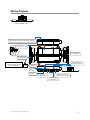
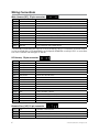
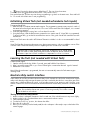
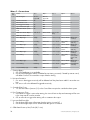
Responder HD Models Viper 5902 Clifford 590.2X Python 592 Security and Remote Start Installation Guide This product is intended for installation by a professional installer only! Attempts to install this product by a person other than a trained professional may result in severe damage to a vehicle’s electrical system and components. © 2009 Directed Electronics, Vista, CA N5902 2009-09b Bitwriter®, Code Hopping™, Doubleguard®, ESP™, FailSafe®, Ghost Switch™, Learn Routine™, Nite-Lite®, Nuisance Prevention® Circuitry, Revenger®, Silent Mode™, Soft Chirp®, Stinger®, Valet®, Vehicle Recovery System®, VRS®, and Warn Away® are all Trademarks or Registered Trademarks of Directed Electronics. The Bitwriter® (p/n 998U) requires chip version 2.7 or newer to program this unit. Bitwriters with a date code of 6a or older require an IC upgrade (p/n 998M). Some bitwriters with a date code of 6B do not require the IC upgrade, refer to tech tip # 1112 for more information. Contents Warning! safety first......................................................................................................................... 4 Wiring Diagram.............................................................................................................................. 5 Wiring Connections......................................................................................................................... 6 Main Harness (H1), 12-pin connector........................................................................................... 6 H2 Harness, 18-pin connector .................................................................................................... 6 Remote Start, (H3) 10-pin connector............................................................................................. 6 Door Lock, 3-pin connector.......................................................................................................... 7 Adjusting the Sensor......................................................................................................................... 7 Initializing Virtual Tach (not needed w/hardwire tach inputs)................................................................. 8 Learning the Tach (not needed with Virtual Tach).................................................................................. 8 Neutral safety switch interface........................................................................................................... 8 Testing the neutral safety switch.................................................................................................... 8 Remote Start Shutdown/Startup Diagnostics........................................................................................ 9 Remote Pairing.............................................................................................................................. 10 Programming System Features......................................................................................................... 11 Feature Menus............................................................................................................................... 12 Menu 1 - Security..................................................................................................................... 12 Menu 2 - Convenience.............................................................................................................. 14 Menu 3 - Remote start............................................................................................................... 16 Bitwriter - Only Options.................................................................................................................. 18 Basic Remote Functions................................................................................................................... 20 Reset and Deletion......................................................................................................................... 20 Table of Zones............................................................................................................................... 21 Troubleshooting: Alarm................................................................................................................... 21 Troubleshooting: Remote Start.......................................................................................................... 22 Warning! safety first The following safety warnings must be observed at all times: • Due to the complexity of this system, installation of this product must only be performed by an authorized Directed Electronics dealer. • When properly installed, this system can start the vehicle via a command signal from the remote control. Therefore, never operate the system in an area that does not have adequate ventilation. The following precautions are the sole responsibility of the user; however, authorized Directed Electronics dealers should: • Never use a test light or logic probe when installing this unit. Always use a multimeter. • Never operate the system in an enclosed or partially enclosed area without ventilation (such as a garage). • When parking in an enclosed or partially enclosed area or when having the vehicle serviced, the remote start system must be disabled using the installed toggle switch. It is the user’s sole responsibility to properly handle and keep out of reach from children all remote controls to assure that the system does not unintentionally remote start the vehicle. • USER MUST INSTALL A CARBON MONOXIDE DETECTOR IN OR ABOUT THE LIVING AREA ADJACENT TO THE VEHICLE. ALL DOORS LEADING FROM ADJACENT LIVING AREAS TO THE ENCLOSED OR PARTIALLY ENCLOSED VEHICLE STORAGE AREA MUST REMAIN CLOSED AT ALL TIMES. Use of this product in a manner contrary to its intended mode of operation may result in property damage, personal injury, or death. Except when performing the Safety Check outlined in this installation guide, (1) Never remotely start the vehicle with the vehicle in gear, and (2) Never remotely start the vehicle with the keys in the ignition. The user is responsible for having the neutral safety feature of the vehicle periodically checked, wherein the vehicle must not remotely start while the car is in gear. This testing should be performed by an authorized Directed Electronics dealer in accordance with the Safety Check outlined in this product installation guide. If the vehicle starts in gear, cease remote start operation immediately and consult with the user to fix the problem immediately. After the remote start module has been installed, test the remote start module in accordance with the Safety Check outlined in this installation guide. If the vehicle starts when performing the Neutral Safety Shutdown Circuit test, the remote start unit has not been properly installed. The remote start module must be removed or properly reinstalled so that the vehicle does not start in gear. All installations must be performed by an authorized Directed Electronics dealer. OPERATION OF THE REMOTE START MODULE IF THE VEHICLE STARTS IN GEAR IS CONTRARY TO ITS INTENDED MODE OF OPERATION. OPERATING THE REMOTE START SYSTEM UNDER THESE CONDITIONS MAY RESULT IN PROPERTY DAMAGE OR PERSONAL INJURY. IMMEDIATELY CEASE THE USE OF THE UNIT AND REPAIR OR DISCONNECT THE INSTALLED REMOTE START MODULE. DIRECTED ELECTRONICS WILL NOT BE HELD RESPONSIBLE OR PAY FOR INSTALLATION OR REINSTALLATION COSTS. Remote starters for manual transmission pose significant risks if not properly installed and operated. When testing to ensure the installation is working properly, only remote start the vehicle in neutral gear, on a flat surface and with a functional, fully engaged parking brake. Do not allow anyone to stand in front of or behind the vehicle. This product should not be installed in any convertible vehicles, soft or hard top with a manual transmission. Installation in such vehicles may pose certain risk. 4 © 2009 Directed Electronics. All rights reserved. Wiring Diagram Menu Wheel Menu Wheel Menu Wheel Control button Status LED Control Center 6711T D2D jumpers; Factory setting is horizontal position. Most Xpresskit modules use this setting, check the Xpresskit installation guide for the specific setting. MINI ATM RPN: 8540 10A FUSE + - (10A (MAXIMUM) FUSE JUMPER) LIGHT FLASH POLARITY LIGHT FLASH POLARITY (10A (MAXIMUM) FUSE JUMPER) + - 10A FUSE MINI ATM RPN: 8540 Remote Start (H3) (see wiring tables) Main Harness (H1) (see wiring tables) CPU1 IMPORTANT! Neutral Safety switch must be plugged in and in the ON position Optional Mux Port (for additional sensors) Neutral Safety Switch ON RF Port for IVU Bitwriter Port Control Center Temperature Sensor D2D Port (for external Xpresskit interface module) Door Lock (see wiring tables) H2 Harness (see wiring tables) 1 12 1 9 8 7 6 5 4 3 2 1 10 1 8 1 1 10 5 3 1 18 10 9 1 © 2009 Directed Electronics. All rights reserved. 12 5 (for external Xpresskit Bitwriter Neutral Safety interface Port Switch module) 10A FUSE MINI ATM RPN: 8540 Remote Start In Door Lock/ Unlock Output H2 Port To change threshold OFF: Main Harness TACH (H1), 12-pin connector H1/1 RED/WHITE H1/2 RED H1/3 H1/4 Valet Port Status LED Optional Mux P (for additional sen CPU1 jumper settings Wiring Connections TACH threshold ON: Relay Out Port 1 12 10 9 8 7 6 5 4 3 2 1 (-) 200mA AUX/TRUNK OUTPUT 10 1 Bitwriter (+)12VDC CONSTANT Port INPUT IMPORTANT! Neutral Safety 1 8 switch must be plugged in Neutral Safety BROWN (+) SIREN OUTPUT and in the ON position ON 1 Switch 5 WHITE/BROWN PARKING LIGHT ISOLATION WIRE - PIN 87a of onboard relay H1/5 BLACK (-) CHASSIS GROUND H1/6 VIOLET (+) DOOR TRIGGER INPUT H1/7 BLUE (-) TRUNK PIN/ INSTANT TRIGGER INPUT (N/C OR N/O) H1/8 GREEN (-) DOOR TRIGGER INPUT (N/C* OR N/O) H1/9 BLACK/WHITE (-) 200mA DOME LIGHT SUPERVISION OUTPUT H1/10 WHITE/BLUE 10 9 8 7 6 (-) REMOTE START/ TURBO 1 12 TIMER ACTIVATION INPUT H1/11 WHITE PARKING LIGHT OUTPUT H1/12 ORANGE (-) 500mA GROUND WHEN ARMED OUTPUT 1 1 Valet Port Status LED ELECTRONICS 3 1 5 4 3 2 12 1 10 1 8 MINI ATM RPN: 8540 1 + - 10A FUSE (10A (MAXIMUM) FUSE JUMPER) LIGHT FLASH POLARITY *The Normally Closed setting will only work if 5one of the vehicle's doors is connected. If more than one door 1 is to be monitored, then it is recommended to use the Xpresskit DTIMAZDA or tech tip # 1921 on www.direct1 3 echs.com to interface with these types of vehicles. H2 Harness, 18-pin connector 18 10 9 1 H2/1 LIGHT GREEN/BLACK (-) 200mA OEM ALARM DISARM OUTPUT H2/2 ORANGE/BLACK (-) 200mA AUX 4 OUTPUT H2/3 GREEN/WHITE (-) 200mA OEM ALARM ARM OUTPUT H2/4 VIOLET/BLACK (-) 200mA AUX 2 OUTPUT H2/5 WHITE/BLACK (-) 200mA AUX 3 OUTPUT H2/6 WHITE/VIOLET (-) 200mA AUX 1 OUTPUT H2/7 GREY/BLACK (-) DIESEL WAIT TO START INPUT H2/8 BROWN/BLACK (-) 200mA HORN HONK OUTPUT H2/9 VIOLET/WHITE TACHOMETER INPUT TACH threshold OFF: BLUE H2/10 DARK TACH threshold ON: H2/11 PINK/WHITE To change jumper settings 12 CPU1 (-) 200mA STATUS OUTPUT NOTE: Pin 1 is on the left (-) 200mA FLEX RELAY CONTROL OUTPUT H2/12 ORANGE (-) 200mA ACCESSORY OUTPUT H2/13 PURPLE H2/14 PINK H2/15 GREY (-) HOOD PIN INPUT (N/C OR N/O) H2/16 BLUE/WHITE (-) 200mA 2ND STATUS /REAR DEFOGGER OUTPUT H2/17 BROWN (+) BRAKE SHUTDOWN INPUT H2/18 BLACK/WHITE (-) NEUTRAL SAFETY INPUT 200mARemote STARTER OUTPUT Bitwriter Neutral(-)Safety Door Lock/ Port Switch Start In Unlock Output (-) 200mA IGNITION 1 OUTPUT 1 12 Remote Start, (H3) 10-pin connector 1 H2 Port 10 9 8 7 6 5 4 3 2 1 Relay Out Port Valet Port Status LED 10 H3/1 PINK (+) IGNITION 1 INPUT/OUTPUT H3/2 RED/WHITE 1 (87) FLEX RELAY +12V INPUT (30A FUSED) H3/3 ORANGE 1 5 ACCESSORY OUTPUT (+) H3/4 VIOLET 1 8 R 3 1 12 5 6 7 12 1 11 1 89 0 4 TACH LEARN THREASHOLD JMP1 OFF 6 © 2009 Directed Electronics. All rights reserved. ON 23 1 0 08 9 10 0 11 6 (+) STARTER OUTPUT (CAR SIDE OF THE STARTER KILL) 07 3 4 2 ELECTRONICS Bitwriter Neutral Safety Port Switch Remote Start In Door Lock/ Unlock Output H2 Port Relay Out Port H3/5 GREEN (+) STARTER INPUT (KEY SIDE OF THE STARTER KILL) H3/6 RED IGNITION 1 +12V INPUT (30A FUSED) H3/7 PINK/WHITE (30) FLEX RELAY OUTPUT (car side of10ign,9 acc8 or 7starter wire) 6 H3/8 PINK/BLACK (87a) FLEX RELAY INPUT (key side of ign, acc or starter wire if needed) 1 12 1 5 4 3 2 Valet Port Status LED 1 10 H3/9 RED/BLACK ACCESSORY/STARTER RELAY +12V INPUT (30A FUSED) H3/10 NC 1 No Connection 8 R 1 5 ELECTRONICS 4 2 3 1 10 NOT USED 3 GREEN (-) 500mA LOCK OUTPUT 1 89 0 6 7 EMPTY 12 5 2 1 4 (-) 500mA UNLOCK OUTPUT TACH LEARN THREASHOLD JMP1 OFF Adjusting the Sensor Important! Make sure the keypad is unlocked and the vehicle is disarmed with no open zones. The on board shock sensor can be adjusted using the HD remote. Adjusting the sensor: 1. Disarm the system, turn the ignition Off and close all the doors. 2. To enter Sensor Adjust, press in and hold the menu wheel (for 3 seconds) on the remote control while the display is blank. When the Settings screen appears, toggle the menu wheel up or down to the Adjustments screen and then press in on the menu wheel to enter. 3. In the Adjustments menu, highlight Sensor Adjust and press the Menu Wheel. The remote requests the current setting from the system and displays it in the Sensor Adjustment screen. 4. Follow the on screen instructions to change the setting in the display. 5. Toggle the menu wheel up/down or press the / buttons to change level. 6. When you have reached the desired level, press and hold the menu wheel, the remote sends the level setting in the display to the system; a long beep confirms the new level is set. To reset the level to factory default, press the button. Note: You can test the new setting by cautiously impacting the vehicle with increasing intensity until the siren chirps, indicating the impact level required to fully trigger the alarm. 7. Press the button to exit and return to the Adjustments menu. The setting retains the last saved. AUX AUX AUX AUX To exit the shock sensor adjustment mode from the control module: Open an entry point or turn on the ignition, the control module emits one long chirp exiting adjustment mode. During level setting and level testing if more than 30 seconds lapses without any action the system will exit sensor adjust and return to the Adjustment menu. Adjusting the sensor with the 1way remote: 1. Disarm the system, turn the ignition Off and close all the doors. 2. Press and hold the button of the remote control for 8 seconds (If Car 2 mode is on, ignore the Car Select beep after 3 seconds) or until the amber LED turns on. 3. Press and hold the button 1.5 seconds or until the amber led flashes then comes on solid.- The control module emits one long chirp, confirming that it has entered adjustment mode. 4. Press the , or buttons to adjust the sensor level. Note: You can test the new setting by cautiously impacting the vehicle with increasing intensity until the siren chirps, indicating the impact level required to fully trigger the alarm. AUX AUX AUX AUX AUX • button: Pressing this button increases the sensitivity one level. The siren chirps twice confirming the sensitivity adjustment. • button: Pressing this button decreases the sensitivity one level. The siren chirps once confirming the sensitivity adjustment. AUX AUX © 2009 Directed Electronics. All rights reserved. 7 ON 23 BLUE 12 1 11 1 0 08 9 Door Lock, 3-pin connector 3 07 0 11 6 1 • button: Pressing this button resets to default level 7. The siren chirps three times. To exit the shock sensor adjustment mode from the 1 way remote control: Press and release the button any time during programming to go back to the main menu. Press and hold for 1.5 seconds in the main menu to exit programming. AUX AUX Initializing Virtual Tach (not needed w/hardwire tach inputs) To program Virtual Tach: 1. After the install is complete, remote start the engine. The programming operation may require 3 cranks of the starter before the engine starts and runs. Do not turn off the remote start if this happens, it is a normal programming operation. 2. Once the engine begins running, let it run for at least 30 seconds. 3. Using the Remote, send the Remote start command to turn remote start off. Virtual Tach is programmed. To reset Virtual Tach, go into the Reset and Deletion section of this guide. Virtual Tach cannot be reset with the Bitwriter. Note: Virtual Tach cannot be used in MTS Manual Transmission Mode. It is also not recommended for diesel trucks. Virtual Tach handles disengaging the starter motor during remote starting – it does not address over-rev. If the customer wants to have the over-rev protection capability, the tach wire must be connected. Important: After successfully learning Virtual Tach, a small minority of vehicle starters may over crank or under crank during remote start. The Bitwriter can be used fine tune the starter output time in 50mS increments to compensate for such an occurrence. Learning the Tach (not needed with Virtual Tach) To learn the tach signal: 1. Start the vehicle with the key. Within 5 seconds, press and hold the Control button. 2. After 3 seconds the status LED on your Control Center lights constant when the tach signal is learned. 3. Release the Control button. Note: When the tachometer is programmed, the main unit automatically enters the Tachometer engine checking mode. Neutral safety switch interface Some vehicles do not have an electrical neutral safety switch. Instead, the vehicle has a mechanical neutral safety switch that physically interrupts the starter wire and is used when the vehicle is in any drive gear. If the remote start is interfaced before this switch, it will provide protection from starting in gear. However, some vehicles combine the column shift mechanism and the mechanical neutral safety switch into one mechanical part. Important: You must complete the remote start system installation before doing the following test. Ensure that the remote start system is functioning normally. This includes connecting to the brake as a shut-down. Testing the neutral safety switch 1. 2. 3. 4. 5. 6. 8 Make sure there is adequate clearance to the front and rear of the vehicle because it may move slightly. Make sure the hood is closed and there are no remote start shut-downs active. Set the emergency brake. Turn the key to the “run” position, this releases the shifter. Place the car in drive (D). Place your foot directly over the brake pedal, but do not depress it. Be ready to step on the brake if the starter engages. © 2009 Directed Electronics. All rights reserved. 7. Activate the remote start system. 8. If the starter engages, immediately depress the brake to shut the remote start system down. If the starter does not engage, no additional safety system is required. If the starter engages and the vehicle is a General Motors product or Dodge Dakota pickup, refer to www.directechs.com for Document 1008 under the Resource tab. For an alternative shut-down method which prevents the starter from engaging. If the vehicle is not a General Motors product or a Dodge Dakota pickup, please call Directed Electronics Technical Support for an alternative shut-down method. Do not return the vehicle to the customer until this feature is properly installed! Remote Start Shutdown/Startup Diagnostics Shutdown diagnostics: If the remote start activates but fails to stay running, the remote start module has the ability to inform you of what may have caused the remote start failure. Before performing shutdown diagnostics it is important that you let the remote start shut off on its own i.e. let it attempt to start 3 times then shut down, if this is not done the unit will report the shutdown you used to shut off the remote start. Note: Shutdown diagnostics does not report if the vehicles factory immobilizer is causing the problem. To perform shutdown diagnostics: 1. With the ignition Off, press and hold the Control button (on Control Center). 2. Turn the ignition On and then back Off while holding the Control button. 3. Release the Control button. 4. Press and release the Control button. The status LED flashes to report the last shutdown for one minute or until the ignition is turned on, as shown in the following table: Status LED Flashes 1 flash 2 flashes 3 flashes 4 flashes 5 flashes 6 flashes 7 flashes 8 flashes 9 flashes 10 flashes 11 flashes * ** Shutdown Mode Runtime expired Over-rev shutdown Low or no RPM Transmitter shutdown (or optional push button) (+) Brake shutdown (-) Hood shutdown Timer mode/Turbo mode/Manual mode error * Neutral safety shutdown Low battery (voltage mode) Alarm triggered ** Wait-to-start input timed out Timer mode error: Ignition is on or shutdown input is active when activating timer mode. Turbo mode error: Turbo mode is programmed off, engine is not on or shutdown input is active. Manual mode error: MTS mode not enabled. Alarm was triggered during remote start sequence. Startup Diagnostics: If the vehicle fails to activate the remote start, the remote start module will notify you via your Responder HD 2-way remote control and will flash the parking lights on the vehicle to notify you of what caused the no-start situation. Parking Light Flashes 5 flashes 6 flashes 7 flashes 8 flashes Brake wire is active Hood pin wire is active Manual transmission mode is enabled and not initialized. Neutral safety wire has no ground or the neutral safety switch is Off. © 2009 Directed Electronics. All rights reserved. 9 Remote Pairing Prepare the vehicle system to be Paired with a new remote 1. Open a door. 2. Turn the key to the ON position. 3. Within 5 seconds press and release the Control button on the Control Center one time. 4. Within 5 seconds, press and hold the Control button on the Control Center. The status LED will flash one time and the siren then chirps to confirm the vehicle is ready for remote pairing. 5. Release the Control button and proceed below. Note: If no remote pairing results, the system will exit after 60 seconds. Prepare the Responder HD 2-way remote control to be Paired with the system: Remote Pair matches your HD remote to the system. Make sure the HD remote is set for the desired Car 1 (Default) or Car 2 operation for the system it will be paired with. 1. With the HD remote control display blank, press in and hold the menu wheel for 3 seconds until Settings screen appears. 2. Toggle the menu wheel until Adjustments screen appears 3. Press in on the menu wheel to enter. 4. In the Adjustments menu highlight Remote Pair and press in the Menu Wheel to go to the Remote Pair screen. Follow the on screen instructions: I. Press and hold the button until tones are played. II. The system chirps the siren to indicate it has learned the HD remote ID and is sending its ID to the remote. III. Release button. 5. Successful or Failed Pair: The HD remote control indicates a successful or failed pairing on the display. After a successful pairing, it then returns to the Adjustments menu. If pairing fails, it returns to the Remote Pair screen, press the button to attempt another pairing. AUX AUX AUX Prepare the vehicle system to be Paired with the companion or a new 1-way remote as described above. Note: If no remote pairing results, the system will exit after 60 seconds. Prepare the companion 1-way remote control to be Paired with the system: Make sure the remote is set for the desired Car 1 (Default) or Car 2 operation for the system it will be paired with. AUX 1. Press and hold the button for 8 seconds. Note: If Car 2 mode is on, ignore the Car Select beep after 3 seconds. 2. Wait for the Transmit LED to light solid and the remote to beep. Release the button. 3. Press the button for 1 second. The transmit LED will blink 3 times and beep 3 times. 4. Within 5 seconds, press the button. 5. The vehicle siren will chirp. You have now successfully learned the remote to the vehicle remote start and security system. 6. Press the button two times to exit learn routine on the remote. The transmit LED will turn off and exit tone will sound. AUX AUX AUX AUX 10 © 2009 Directed Electronics. All rights reserved. Programming System Features The System Features Learn Routine dictates how the unit operates. It is possible to access and change most of the feature settings using the Control button. 1. Open a door. 2. Turn the ignition on, then off. 3. Select a Menu. Press and hold the Control button. The number of siren chirps indicates the menu number. 1 chirp indicates menu 1, 2 chirps - menu 2 and 3 chirps for menu 3. 4. When the desired menu chirps are heard, release the Control button. 5. Select a Feature. Press and release the Control button the number of times corresponding to the feature you wish to change. Then press and hold one more time to select the features. 6. Program the Feature. While holding the Control button, you can program the feature using the remote control. For features with only two options; = option 1 while = option 2. For features with more than two options; selects the options in ascending order, while descending order. AUX Note: Pressing selects them in AUX AUX AUX button resets the feature to the factory default. AUX Once a feature is programmed: • Other features can be programmed within the same menu • Another menu can be selected • The learn routine can be exited if programming is complete To access another feature in the same menu: 1. Press and release the Control button the number of times necessary to advance from the feature you just programmed to the next one you want to program. 2. Then press the Control button once more and hold it. To select another menu: 1. Press and hold the Control button. 2. After 3 seconds, the unit advances to the next menu and the siren chirps, indicating which menu has been accessed. The learn routine exits if any of the following occurs: • The open door is closed • The ignition is turned On • There is no activity for 30 seconds • The Control button is pressed too many times © 2009 Directed Electronics. All rights reserved. 11 Feature Menus Default settings are Opt. 1 (in bolder type). New features are bold with grey background. Menu 1 - Security Menu Item Feature Opt. 1 Opt. 2 Opt. 3 Opt.4 Opt. 5+ 1 System Arming Mode Active Passive Arm w/o lock Passive Arm w/lock Auto re-arm w/o lock Auto re-arm w/ lock 2 Panic Mode On Ign Off only Off 3 Confirmation Chirps On w/Warn chirps On On w/Warn chirps Off Off w/ Warn chirps On Off w/ warn chirps Off 4 Siren Duration 30 sec. 60 sec. 5 Ign-controlled Locks No Ign- locking Lock & Unlock Lock Only Unlock Only 6 Door Lock Pulses Single Double Unlock Only Double Lock Only Double Lock & Unlock 7 Door Lock Output Duration 0.8 sec. 3.5 sec. 0.4 sec. 8 Ignition Controlled 2nd Unlock 2nd unlock on Ign-control after first unlock 2nd unlock on Ign-control with first unlock 9 Comfort Closure No Comfort Closure Comfort Closure 1 Comfort Closure 2 10 Horn Function Full Alarm Only Siren Function 20 ms Siren Function 30 ms 11 Hood Switch type Normally Open Normally closed 12 Sensor Full trigger Single Double 13 Door Switch Type Normally open Normally closed 14 Trunk Switch Type Normally open Normally closed 15 Remote Button unlock (Ign off) On Off Siren Function 40 ms Siren Function 50 ms 1. System Arming mode 1. Active: the transmitter must be used to arm the system 2. Passive Arm w/o lock: after exiting the vehicle the system will automatically arm. The doors will not lock 3. Passive Arm w/lock: after exiting the vehicle the system will automatically arm and lock the doors 4. Auto re-arm w/o lock: if the vehicle is not entered after receiving a disarm command, the system will automatically re-arm. The doors will not lock 5. Auto re-arm w/lock: if the vehicle is not entered after receiving a disarm command, the system will automatically re-arm and lock the doors 2. Panic Mode 1. On: the Panic output can be activated at any time 2. Ign Off Only : the Panic output can be activated only when the ignition is off 3. Off: the Panic output is defeated 3. Confirmation Chirps 1. On w/Warn Chirps On: arm, disarm, and sensor warn-away chirps are active 2. On w/Warn Chirps Off: arm and disarm chirps are active, warn-away chirps are defeated 3. Off w/Warn Chirps On: arm and disarm chirps are defeated, warn-away chirps are active 4. Off w/Warn Chirps Off: arm, disarm, and sensor warn-away chirps are defeated 12 © 2009 Directed Electronics. All rights reserved. 4. Siren Duration 1. 30sec: the siren output for full trigger activations and Panic mode is 30 seconds 2. 60sec: the siren output for full trigger activations and Panic mode is 60 seconds 5. Ign-controlled Locks 1. No Ign-locking: the door lock/unlock outputs will not activate when ignition is turned on/off 2. Lock & Unlock: the door lock & unlock output will activate when ignition is turned on & off 3. Lock Only: the door lock output will activate when ignition is turned on 4. Unlock Only: the door unlock output will activate when ignition is turned off 6. Door Lock Pulses 1. Single: the door lock & unlock outputs will pulse once 2. Double Unlock only: the unlock output only will pulse twice 3. Double Lock Only: the lock output only will pulse twice 4. Double Lock & Unlock: the lock & unlock outputs will pulse twice 7. Door Lock Output Duration 1. 0.8sec.: the door lock output pulses will be 800mS in duration 2. 3.5sec.: the door lock pulses will be 3.5 seconds in duration 3. 0.4 sec.: the door lock pulses will be 400mS in duration 8. Ignition Controlled 2nd Unlock 1. After first unlock: for Ign-controlled unlocking, the 2nd unlock will activate 800mS after the first (driver door) unlock 2. With first unlock: for Ign-controlled unlocking, the 2nd unlock will activate at the same time as the first (driver door) unlock 9. Comfort Closure 1. No comfort Closure: Comfort Closure is defeated when arming 2. Comfort Closure 1: the door lock pulse (or 2nd pulse for double pulses) will remain on for 20 seconds. 3. Comfort Closure 2: 800mS following the end of the door lock pulse (or 2nd pulse for double pulses); the door lock output will turn on again for 20 seconds. 10. Horn Function 1. Full Alarm Only: the horn output will pulse only during full trigger events. 2. Siren Function 20/30/40/50ms: The horn output will emulate the siren output with selectable output timing to compensate for OEM horn inefficiency. 11. Hood Switch Type 1. Normally Open: for vehicles with a hood switch that rests at ground when the hood is OPEN 2. Normally Closed: for vehicles with a hood switch that rests at ground when the hood is CLOSED 12. Sensor Full Trigger 1. Single: full trigger activation of only one sensor is required to fully trigger the alarm 2. Double: full trigger activation of two sensors within a ten second period is required to fully trigger the alarm. 13. Door Switch Type 1. Normally Open: for vehicles with door switches that rest at ground when the door is OPEN 2. Normally Closed: for vehicles with door switches that rest at ground when the door is CLOSED 14. Trunk Switch Type 1. Normally Open: for vehicles with a trunk switch that rests at ground when the trunk is OPEN 2. Normally Closed: for vehicles with a trunk switch that rests at ground when the trunk is CLOSED 15. Remote Button Unlock (Ign off) 1. On: a message telling the 2-way remote control to unlock the keypad is sent each time the vehicle ignition is turned off 2. Off: no message is sent © 2009 Directed Electronics. All rights reserved. 13 Menu 2 - Convenience Menu Item Feature Opt. 1 Opt. 2 Opt. 3 Opt.4 Opt. 5+ 1 One-time Bypass One time bypass Off One time bypass On 2 Nuisance Prevention On Off 3 Override Pulse count 1 2 3 4 5 4 Door Trigger Error Chirp On Off 5 Ign-controlled Dome light On Off 6 OEM Alarm Disarm w/AuxTrunk On Off 7 OEM Alarm Disarm Output With Unlock Before Unlock 8 OEM Alarm Disarm Pulses 1 2 9 Aux 1 Output type Validity Latch Latch/reset/ign 30 sec. Timed Off (5)/2nd unlock (6) 10 Aux 1 Linking No Linking Link to Arm Link to Disarm Link to Arm/ disarm Link to Remote Start only 11 Aux 2 Output Type Validity Latch Latch reset/ign 30 sec. Timed Off (5)/2nd unlock (6) 12 Aux 2 Linking No Linking Link to Arm Link to Disarm Link to Arm/ Disarm Link to Remote Start only 13 Aux 3 Output Type Validity Latch Latch reset/ign 30 sec. Timed Off (5)/2nd unlock (6) 14 Aux 3 Linking No Linking Link to Arm Link to Disarm Link to Arm/ Disarm Smart Key Control (Link to Remote Start Off) 15 Aux 4 Output Type Validity Latch Latch reset/ign 30 sec. Timed Off (5)/2nd Unlock (6) 16 Aux 4 Linking No linking Link to Arm Link to Disarm Link to Arm/ Disarm Link to Remote Start Only 17 Aux/Trunk Output type Validity Off 2nd unlock Remote Start Only 1. One-time Bypass 1. Off: One-Time Bypass is not available 2. On: the One-Time Bypass feature will defeat Passive Arming once and, if Armed by remote control, will defeat Comfort Closure and Aux outputs linked to Arming 2. Nuisance Prevention 1. On: sensors that trigger excessively will be defeated until they have been stable for more than one hour 2. Off: sensors will not be defeated if triggered excessively 3. Override Pulse Count • 1-5: sets the number of presses (1-5) on the Control Button required to override the alarm system 4. Door Trigger error Chirp 1. On: if the door trigger is active when arming, the siren will emit a chirp and a message will be sent to the 2way remote control as an alert 2. Off: an active door trigger when arming will not create an alert output 5. Ign-controlled Dome light 1. On: the dome light output will activate when the ignition is turned off 2. Off: the dome light output will not activate when the ignition is turned off 6. OEM Alarm Disarm w/Aux/Trunk (H2/1 wire) 14 © 2009 Directed Electronics. All rights reserved. 1. On: the OEM Alarm Disarm wire will pulse as programmed when the Aux/Trunk output is activated 2. Off: the OEM Alarm Disarm wire will not pulse when the Aux/Trunk output is activated 7. OEM Alarm Disarm Output (H2/1 wire) 1. With Unlock: the OEM Alarm Disarm wire will pulse as programmed at the same time as the unlock (Blue) wire 2. Before Unlock: the OEM Alarm Disarm wire will pulse as programmed before the unlock wire 3. Remote start only: the OEM Alarm Disarm wire will pulse as programmed during remote start only 8. OEM Alarm Disarm Pulses (H2/1 wire) 1. 1: the OEM Alarm Disarm wire will pulse once per operation 2. 2: the OEM Alarm Disarm wire will pulse twice per operation 9. Aux 1 Output Type (H2/6 wire) 1. Validity: when the Aux command is received the wire will turn on and remain on until the command ceases 2. Latch: when the Aux command is received the wire will turn on and remain on until the command is received again 3. Latch/reset/Ignition: when the Aux command is received the wire will turn on and remain on until the command is received again or the ignition is turned on/off 4. Timed: when the Aux command is received the wire will turn on for the programmed time duration (default 30sec) 5. Off: the output will not activate for a remote control command, use this option when the Aux command controls an external device such as a garage door module 6. 2nd unlock: the wire will operate as 2nd unlock and will not activate for remote control commands 10. Aux 1 Linking 1. No Linking: the Aux output will not activate for a remote control command 2. Link to Arm: the Aux output will activate for the Arm command 3. Link to Disarm: the Aux output will activate for the Disarm command 4. Link to Arm/Disarm: the Aux output will activate for the Arm & Disarm commands 5. Link to Remote Start: the Aux output will activate for any Remote Start activation 11. Aux 2 Output Type • Refer to Aux 1 Output Type descriptions 12. Aux 2 Linking • Refer to Aux 1 Linking descriptions 13. Aux 3 Output Type • Refer to Aux 1 Output Type descriptions 14. Aux 3 Linking • Options 1-4: Refer to Aux 1 Linking descriptions • Option 5: SmartKey Control (Link to Remote Start Off): The Aux output will pulse once following Remote Start shut down for vehicles with push button engine stop operations. During runtime, if any door is opened remote start will shut down immediately and pulse the output. 15. Aux 4 Output Type • Refer to Aux 1 Output Type descriptions 16. Aux 4 Linking • Refer to Aux 1 Linking descriptions 17. Aux/Trunk Output Type • Refer to Aux 1 Output Type descriptions © 2009 Directed Electronics. All rights reserved. 15 Menu 3 - Remote start Menu Item Feature Opt. 1 Opt. 2 Opt. 3 Opt.4 1 Transmission Mode Manual Automatic 2 Engine Checking Mode Virtual Tach 3 Cranking Time 0.6 sec. Voltage Off Tachometer 0.8 sec. 1.0 sec. 1.2 sec. 1.4 (5)/ 1.6 (6)/ 1.8 (7) 2.0 (8)/ 4.0 (9) 60 min. On- 10 min. 4 Remote Start Runtime 12 min. 24 min. 5 Activation Pulse Count 1 2 6 Turbo Mode No Turbo Mode On-1 min. On-3 min. On-5 min. 7 Timer Mode Runtime 12 min. 3 min. 6 min. 9 min. 8 Flex Relay Function Ignition 2 Accessory 2 Starter 2 9 Diesel Start Delay Wait-to Start input Timed 15 sec. Timed 30 sec. 10 Accessory during Diesel Start Delay On Off 11 Status 2 Output Status Latch Rear Defogger Pulse Rear Defogger 12 Parking Light Output Constant Pulsed Off 13 Anti-grind Output On Off 14 Tach Mode Starter Release Normal Increase 15 Vehicle Temp Auto Report Off On 16 Remote Start Safelock Off On Opt. 5+ Timed 45 sec. Decrease 1. Transmission Mode 1. Manual: requires ‘Tachometer’ for the Engine Checking Mode, and requires the user to successfully perform a procedure when parking the vehicle before remote starter will engage 2. Automatic: uses any of the Engine Checking Modes and does not require any special procedures when parking 2. Engine Checking Mode 1. VirtualTach: battery voltage drop/rise during cranking determines when the starter output is released. During runtime, constant voltage level is monitored to determine if the engine is running 2. Voltage: starter output during cranking is a programmed duration (Set in Cranking Time). During runtime, constant voltage level is monitored to determine if the engine is running 3. Off: starter output during cranking is a programmed duration (Set in Cranking Time). The remote start will keep the ignition/accessories active for the programmed runtime whether the engine is running or not 4. Tachometer: tachometer input signal during cranking and runtime to determine when the starter output is released and if the engine is running. 3. Cranking Time • 0.6/0.8/1.0/1.2/1.4/1.6/1.8/2.0/4.0 seconds: determines the starter output duration during cranking for the ‘Voltage’ and the ‘Off’ Engine Checking Mode options 4. Remote Start Runtime • 12/24/60 minutes: sets engine runtime during normal remote start operations 5. Activation Pulse Count • 1/ 2 pulses: sets the number of remote control commands received or Activation Input required to activate and de-activate remote start 6. Turbo Mode 1. No turbo Mode: Turbo mode is not available 2. On – 1/3/5/10 minutes: Turbo Mode is available and, when activated, the engine will run for the duration set per the selected option 7. Timer Mode Runtime • 12/3/6/9 minutes: sets the runtime when the engine is started by the Timer Mode and SmartStart features 8. Flex Relay Function 1. Ignition 2: the relay will emulate the Ignition 1 output during remote start 2. Accessory 2: the relay will emulate the Accessory 1 output during remote start 3. Starter 2: the relay will emulate the Starter output during remote start 9. Diesel Start Delay 1. Wait-to-start input: (-) input on the Grey/black (H2/7) WTS wire will delay the starter output until the ground ceases. 2. Timed 15/30/45 seconds: delays the starter output per the selected option, the WTS wire does not function. 10. Accessory during Diesel Start Delay 1. On: the Accessory outputs (H/3 high current and H2/12 low current) will be ON during diesel start delay 2. Off: the Accessory outputs (H/3 high current and H2/12 low current) will be OFF during diesel start delay 11. Status 2 Output (Dark Blue H2/10 wire) 1. Status: the output will activate before the ignition outputs turn on, and de-activate after they turn off during remote start 2. Latch rear defogger: the output activates 10 seconds after start if the interior temperature is below 55F. It turns off after 10 minutes or upon remote start off 3. Pulse rear defogger: the output activates (for 800mS) 10 seconds after start if the interior temperature is below 55F. 12. Parking Light Output 1. Constant: the lights will turn on solid during remote start 2. Pulsed: the lights will pulse on/off during remote start 3. Off: the lights will be off during remote start 13. Anti-grind Output 1. On: the high current starter relay will be activated during remote start as anti-grind protection. 2. Off: the high current starter relay will not be activated during remote start, no anti-grind protection is available. 14. Tach Mode Starter Release 1. Normal: the starter output will release normally during cranking (50% of the learned tachometer value) 2. Increase: the starter output will release later during cranking (at 35% of the learned tachometer value) 3. Decrease: the starter output will release sooner during cranking (at 35% of the learned tachometer value) 15. Vehicle Temp Auto Report 1. Off: the report during remote start is defeated 2. On: the report is sent every 2 minutes during remote start if the temperature has changed (+/-) 1 degree since the last report 16. Remote start Safelock 1. Off: the Door lock and Factory Alarm Re-arm outputs will maintain the current status (locked/un© 2009 Directed Electronics. All rights reserved. 17 locked) during remote start and after shut down 2. On: the Door lock and Factory Alarm Re-arm outputs will arm/lock the vehicle during remote start and after shutdown Bitwriter - Only Options If programming with the Bitwriter®, the learn routine can be locked or unlocked. If the learn routine has previously been locked, it must be unlocked with Bitwriter® - this cannot be done manually with the Control button. The Bitwriter® gives you access to a wider range of system options. These features and the adjustments that may be programmed are described in the table below. Menu Item 1 18 Feature Default Opt. 2 Opt. 3 Opt.4 Opt. 5+ Zone 4 Sensor Type None Shock/Omni Field Disturbance Tilt Sensor Glass Break (5)/Ultrasonic (6) 30 sec. Audio Lights/Left dr/Right dr/ Rear Hatch Sunroof Audio/Lights/Left dr/ Right dr/Rear Hatch/ Timed/Latched Sunroof Audio/Lights/Left dr/ Right dr/Rear Hatch/ Timed/Latched Sunroof Audio/Lights/Left dr/ Right dr/Rear Hatch/ Timed/Latched 2 Siren Duration 3 Aux/Trunk Icon Type Trunk Window Options: 1 to 180 sec. 4 Aux 1 Timed Output 30 sec. Options: 1 to 90 sec. 5 Aux 1 Icon Type Pulsed Trunk 6 Aux 2 Timed Output 30 sec. Options: 1 to 90 sec. 7 Aux 2 Icon Type Pulsed Trunk 8 Aux 3 Timed Output 30 sec. Options: 1 to 90 sec. 9 Aux 3 Icon Type Pulsed Trunk 10 Aux 4 Timed Output 30 sec. Options: 1 to 90 sec. 11 Diesel Start Delay Timer 15 sec. Options: 1 to 90 sec. Sunroof Window Window Window 12 Timer Mode Runtime 12 min. Options: 1 to 16 min. 13 Timer Mode Starts 6 starts Options: 1/2/3/4 to 24 (Starts) in increments of 2 14 Timer mode intervals 3 hr. Options: 1/2/3/4 to 24 in 2 hour increments 15 Smart start low temp 0° (F) Options: OFF, -20° to 70° in 10° increments 16 Smart start high temp 100° (F) Options: OFF, 40° to 130° in 10° increments 17 Smart start low battery (volts) 10.5V Options: OFF, 9V to 12.5V in 0.5V increments 18 Sensor 1 Level 7 Options: 0 to 15 in increments of 1 19 Starter Release Fine Tune 6 (normal) Options: 0 to 20 in increments of 1 20 Feature Programming Unlocked Locked 21 Transmitter Programming Unlocked Locked 22 Remote Start Runtime 12 min. Options: 1 to 60 min. 23 Virtual Tach Fine tune Not Initialized Options: Not initialized, 0 to 1000 in 50 millisecond increments © 2009 Directed Electronics. All rights reserved. 1. Zone 4 Sensor Type: sets the Zone 4 (Sensor 2) name to be displayed in the Text Field for Warn-away and Full Trigger activations 2. Siren Duration: sets the Full Trigger output duration in 1 second intervals up to 180 seconds. 3. Aux/Trunk Icon Type: sets the Accessory animation to be displayed on the screen when the Aux/Trunk output is activated/de-activated 4. Aux 1 Timed Output: sets the output duration in 1 second intervals up to 90 seconds for Aux 1 5. Aux 1 Icon Type: sets the Accessory animation to be displayed on the screen when the Aux 1 output is activated/de-activated 6. Aux 2 Timed Output: sets the Aux 2 “Timed” output in 1 second intervals up to 90 seconds 7. Aux 2 Icon Type: sets the Accessory animation to be displayed on the screen when the Aux 2 output is activated/de-activated 8. Aux 3 Timed Output: sets the Aux 3 “Timed” output in 1 second intervals up to 90 seconds 9. Aux 3 Icon Type: sets the Accessory animation to be displayed on the screen when the Aux 3 output is activated/de-activated 10.Aux 4 Timed Output: sets the Aux 4 “Timed” output in 1 second intervals up to 90 seconds 11.Diesel Start Delay Timer: sets the delay before engine crank in 1 second intervals up to 90 seconds for diesel engine vehicles 12.Timer Mode Runtime: sets the duration of runtime when the engine is started by the Timer Mode and Smart Start features 13.Timer mode Starts: sets the number of times the engine will be started by the Timer Mode and Smart Start features 14.Timer mode Intervals: sets the number of hours between engine starts by the Timer Mode and Smart Start features 15.Smart Start Low Temperature: sets the low temperature threshold required for Smart Start to start the engine 16.Smart Start High Temperature: sets the high temperature threshold required for Smart Start to start the engine 17.Smart Start Low battery (Volts): sets the low battery level threshold required for Smart Start to start the engine 18.Sensor 1 level: directly sets the sensor level of the on-board shock sensor 19.Starter Release Fine Tune: adds or subtracts crank time in Tachometer mode in order to overcome engine types that short crank or over-crank on the first start attempt 20.Feature Programming: locks and unlocks the user’s ability to enter the feature menus and manually change the main unit programming using the Control Center 21.Transmitter Programming: locks and unlocks the user’s ability to enter the HHU/Reset menu and manually change any functions using the Control Center 22.Remote Start Runtime: sets the duration of runtime when the engine is started by remote command 23.VirtualTach Fine tune: adds or subtracts crank time in VirtualTach mode in order to overcome engine types that short crank or over-crank on the first start attempt © 2009 Directed Electronics. All rights reserved. 19 Basic Remote Functions See Owner’s guide for functionality details on both the HD and 1-way companion remote control. Reset and Deletion If a feature/virtual tach needs to be reset or the remote controls need to be deleted, use the following procedure. 1. Open a door. (The GREEN wire, H1/8, or the VIOLET, H1/6 must be connected.) 2. Turn the ignition to the ON position (The heavy gauge pink wire must be connected). 3. Within 10 seconds, press and release the Control button: 2 times if you want to delete remotes, 3 times to reset features or 4 times to reset virtual tach. These features are described next. Delete remotes: This feature erases all remotes from the memory of the security system. This is useful in cases when a customer’s remote is lost or stolen. Note: This does not reset the programmed features of the security system or reset the Virtual Tach setting. Reset Features: This resets features all of the security system to the factory default settings. Note: This feature does not delete the remotes from the security system or reset the Virtual Tach setting Virtual Tach Reset: Deletes all previously learned values for Virtual Tach, and on the next remote start sequence the unit begins virtual tach initialization. Note: The “Zap” feature on the Bitwriter does not reset the Virtual tach setting. 4. Once you have selected the function step, press the Control button once more and hold it. The LED flashes and the siren chirps to confirm the selected functional step. Do not release the Control button button on the remote control. The unit chirps to confirm that 5. While holding the control button, press the the feature has been successfully reset. AUX Once the feature is reset, the Control button can be released. Long Term Event History The system stores the last two full triggers in memory. These are not erasable. Each time the unit sees a full trigger, the older of the two triggers in memory is replaced by the new trigger. To access long term event history: 1. With the ignition Off, press and hold the Control button (on Control Center). 2. Turn the ignition On. 3. Release the Control button. 4. Within 5 seconds, press and release the Control button. The status LED flashes in groups indicating the last two zones that triggered the unit for 1 minute or until the ignition is turned off. Refer to table of zones. Note: The Warn Away triggers are not stored to memory and is not reported. 20 © 2009 Directed Electronics. All rights reserved. Table of Zones A zone is represented by the number of status LED flashes used by the system to identify a particular type of input. Zone Description Input Description 1 Trunk Pin H1/7 Blue wire 2 Instant trigger: a heavier impact detected by the onboard shock sensor On board shock sensor. 3 Door switch trigger H1/8 Green or H1/6 Violet wire 4 Instant trigger: For optional sensors Optional MUX port 5 Ignition trigger H3/1 Pink wire 6 Hood Pin H2/15 Grey wire Troubleshooting: Alarm Shock sensor doesn’t trigger the alarm: 1. Was the onboard shock sensor adjusted before the brain was mounted? If so re-adjust the sensor. 2. Has the onboard shock sensor been turned off? The sensor has the ability to be turned off when adjusting. 3. Has the NPC® system been triggered? If so, you hear 5 chirps when disarming. To check this, turn the ignition key on and off to clear the NPC® memory, and then retest the shock sensor. For a detailed description of NPC®, see Nuisance Prevention Circuitry section of the owners guide. Door input does not immediately trigger full alarm. Instead, chirps are heard for the first 3 seconds: • That’s how the progressive two-stage door input works! This is a feature of this system even if the door is instantly closed again, the progression from chirps to constant siren continues. Closing the door triggers the system, but opening the door does not: • Have you correctly identified the type of door switch system? This happens often when the wrong door input has been used. System does not passively arm until it is remotely armed and then disarmed: 1. Is passive arming programmed ON? 2. Are the door inputs connected? Is the H1/7 blue wire connected to the door trigger wire in the vehicle? Either the H1/8 green or the H1/6 violet should be used instead. Door input does not respond with the progressive trigger, but with immediate full alarm: • Does the Status LED indicate that the trigger was caused by the shock sensor? (See Table of Zones section of this guide.) The shock sensor, if set to extreme sensitivity, may be detecting the door unlatching before the door switch sends its signal. Reducing the sensitivity can solve this problem. Door locks operate backwards. • This unit has easily-reversed lock/unlock outputs. Recheck wire connections to see if you have reversed these. © 2009 Directed Electronics. All rights reserved. 21 Troubleshooting: Remote Start The remote start will not activate the remote start 1. Check remote startup diagnostics. 2. Is the neutral safety switch plugged in and turned on? 3. If the vehicle has an automatic transmission, make sure the remote start is programmed for Automatic Transmission mode. 4. Is the remote programmed to the system? 5. Can the remote start be activated manually by applying a ground pulse to the H1/10 White/Blue wire? 6. Check the harnesses and their connections. Make sure that the harnesses are completely plugged into the remote start module. Make sure there are good connections to the vehicle wiring. 7. Check voltage and fuses on the main 12-pin harness and on the heavy gauge remote start harness. The remote start will activate, but the starter never engages. 1. Check for voltage on the purple starter wire two seconds after the remote start becomes active. If there is voltage present, skip to Step 8. If there is not voltage present, advance to Step 2. 2. Check the 30A fuses. 3. If the gray/black wait-to-start wire is detecting ground upon activation, the starter will not crank. 4. Is the tach wire connected? If so disconnect it and remote start the vehicle to see if the purple wire sends out voltage. If you get voltage you will need to go to an alternate tach source, the tach wire you are currently on has a voltage spike upon ignition power up which can cause the remote start to not send out the crank voltage. 5. Is the vehicle a Chrysler or GM with a multiplexed starter wire? The vehicle will not crank if the resistance is incorrect on the multiplexed accessory/starter wire. 6. Is the vehicle a GM? If so the Brown 2nd accessory needs to be powered up on some of the vehicles for the vehicle to crank. 7. If this is a manual transmission vehicle, the clutch will need to be bypassed (see tech tip # 10000 at www.directechs.com) 8. Make sure the purple starter wire is connected on the starter side of the optional starter kill/anti-grind relay. 9. Does the vehicle have an immobilizer? Some immobilizer systems will not allow the vehicle to crank if active. 10.Check connections. The heavy gauge remote start input wires on the heavy gauge 10-pin connector should have a solid connection. “T-taps” or “scotch locks” are not recommended. The vehicle starts, but immediately dies. 1. Does the vehicle have an immobilizer? The vehicle’s immobilizer can cut the fuel and/or spark during unauthorized starting attempts. 2. Is the remote start programmed for virtual tach or voltage sense? If so, the crank time may not be set high enough. Voltage sense will not work on some vehicles. 3. Is the remote start in tach mode? If so has the tach been programmed to the system? 4. Check diagnostics. Sometimes a shutdown will become active during cranking or just after cranking. The vehicle starts, but the starter keeps running. 1. Is the system programmed for engine checking off or virtual tach or voltage sense? When programmed for either of these features, the engine cranks for the pre programmed crank time regardless of how long it takes for the vehicle to actually start. Adjust to a lower cranking time. 2. Was the Tach Learn successful? The LED must light solid and bright to indicate a successful learn. 3. Make sure that there is a tach signal at the purple/white tach input wire of the remote start. If there is not a tach signal, recheck the connection to the vehicle’s tach wire and make sure the wire is not broken or shorted to ground leading to the remote start. 4. Is an ignition or accessory output wire connected to the starter wire of the vehicle? Verify the color of the starter wire in the vehicle and confirm that an ignition or an accessory output is not connected to that wire. The vehicle starts, but will only run for 10 seconds 22 © 2009 Directed Electronics. All rights reserved. 1. Is the remote start programmed for voltage sense? If this does not work, a tach wire should be used. 2. Check shutdown diagnostics. The climate control system does not work while the unit is operating the vehicle. 1. Either the wrong accessory wire is being energized or more than one ignition or accessory wire must be energized in order to operate the climate control system. 2. If the vehicle has an electronic climate control system some will reset when the key is turned off and then back on, unfortunately this is a function of the vehicle and cannot be bypassed. MTS - Manual Transmission Start diagnostics When enabling MTS, if you get a failure notification from the remote or the vehicle fails to remain started check for following: • Tachometer not connected or programmed. • E-brake not connected to the remote start unit. The black/white H2/18 neutral safety wire must have a ground when the parking brake is set. • Foot must be off the brake when activating the MTS mode on the remote. • Is the door open when enabling the MTS mode? If so this would cause the unit to enter Pit Stop Mode and the remote start will continue to run when arming/locking the system. • Is the door input connected? The system needs to see a door open then close after initiating the remote start. • Does the vehicle have a delayed dome light? If you are connected to the dome light wire and the dome light is staying on after arming/locking the system, the system can exit the MTS mode. • Make sure the neutral safety switch is plugged in and turned on. MTS mode exiting diagnostics: If the remote start has entered the MTS mode but exits the mode after the system is armed/locked. Check these for possible causes. • The vehicle door has been opened or the security system has been triggered in your absence. • Does the vehicle have a delayed dome light circuit or does the dome light come on when the ignition is shut off? If so you may need to go to the independent door inputs of the vehicle. • If you are connected to the dome light wire in the vehicle and cannot connect the system to the individual door inputs of the vehicle due to it having normally closed door inputs, you can use the Xpresskit DTIMAZDA module or Tech Tip # 1921 at www.directechs.com to interface with these types of circuits. • The E-brake wire connected to the neutral safety input of the system loses ground when ignition is turned off or after a certain amount of time, with these vehicles unfortunately there is no workaround. • The E-brake wire connected to the neutral safety input of the system has a poor ground. Clean the contacts on the switch or replace the switch. © 2009 Directed Electronics. All rights reserved. 23


![[ Bedienungsanleitung ]](http://vs1.manualzilla.com/store/data/006735880_1-28334984de48ae2c5a8573c29f433271-150x150.png)