1
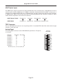
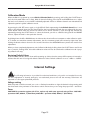
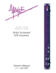
DA-16
24-bit 16-channel
D/A Converter
Owner’s Manual
v1.0 – September 2001
Apogee DA-16 User’s Guide
Written by David Kimm and Julio Alvarez.
Production, editing and running round in circles by Richard Elen, with valuable assistance from Seth Reinhart.
Apogee is a Registered Trademark of Apogee Electronics Corporation. All other trademarks are property of
their respective holders.
Technology within the DA-16 may be covered by one or more patents that are the property of Apogee
Electronics Corporation. Infringement of said patents or any relevant other naughty things may result in one or
more uncomfortable and potentially financially-damaging encounters with members of the legal profession.
Registered User Customer Support:
For customer support, please call (310) 915-1000 and ask for Tech Support,
or email [email protected].
Technical Support is available to registered owners.
Features and specifications subject to change without notice.
© 2001 APOGEE ELECTRONICS CORPORATION
3145 Donald Douglas Loop South
Santa Monica,
California 90405-3210 USA
Tel: +1 310/915-1000
Fax: +1 310/391-6262
Email: [email protected]
Web: http://www.apogeedigital.com/
This manual is copyright ©2001 by APOGEE ELECTRONICS CORPORATION. All rights reserved. Under copyright laws, this manual may not be duplicated in whole or in part without the written consent of Apogee. Just
drop us an email and tell us why you need to copy it.
Page 2
Apogee DA-16 User’s Guide
DA-16
24-bit 16-channel
D/A Converter
Owner’s Manual
v1.0 – September 2001
Apogee DA-16 User’s Guide
Warnings
CAUTION: To reduce the risk of electrical shock, do not remove the cover. No user serviceable parts inside;
refer servicing to qualified personnel. To change the operating voltage or change the firmware EPROM, it is
necessary to remove the cover of the unit. As a result, such operations must be carried out only by technicallyqualified personnel.
WARNING: To reduce the risk of fire or electrical shock, do not expose this appliance to rain or moisture.
This symbol, wherever it appears, alerts you to the presence of uninsulated dangerous voltage inside
the enclosure—voltage that may be sufficient to constitute a risk of shock. Operations indicated with
this symbol should be carried out only by technically-qualified personnel.
This symbol, wherever it appears, alerts you to important operating and maintenance instructions in
the accompanying literature. Read the manual.
Environmental warnings
•
•
•
•
•
•
•
•
•
Never touch the AC plug with wet hands.
Do not use this unit in damp areas or near water.
Avoid damaging the AC plug or cord and potentially causing a shock hazard.
If liquids spill into or onto the DA-16, disconnect the power and return to your dealer for servicing.
This unit should only be connected to an AC power supply of the correct voltage. Check with your dealer
if in doubt.
Precautions should be taken so that the grounding or polarization of the AC power is not defeated.
Unplug the AC cord when the unit is unused for long periods of time.
This unit should only be cleaned as recommended by the manufacturer, or damage to the finish may result.
To avoid potential damage to your unit, only use in areas where proper ventilation and moderate temperatures are assured.
Power warning
AC voltage ratings for electrical power vary from area to area. Severe damage to your unit is possible
if your DA-16 is configured incorrectly for your local power. If in doubt, consult an Apogee dealer. A
label adjacent to the power connector indicates the voltage to which the unit was set on leaving the
factory.
Instructions for changing the power input voltage are provided. We strongly advise you to check that
the voltage label remains current and is updated if the input voltage setting is changed.
FCC warning
This equipment has been tested and found to comply with the limits for a Class A digital device, pursuant to Part 15 of the FCC rules. These limits are designed to provide reasonable protection against
harmful interference when operated in a commercial environment. This equipment generates, uses,
and can radiate radio frequency energy and, if not installed and used in accordance with the instruction manual, may cause harmful interference to radio communications. Operation of this equipment in a residential area
is likely to cause harmful interference, in which case the user will be required to take whatever measures may
be required to correct the interference at his own expense.
Copyright Notice
The Apogee DA-16 is a computer-based device, and as such contains and uses software in ROMs. This software, and all related documentation, including this Owner’s Manual, contain proprietary information which is
protected by copyright laws. All rights are reserved. No part of the software and its related documentation may
be copied, transferred, or modified. You may not modify, adapt, translate, lease, distribute, resell for profit or
create derivative works based on the software and its related documentation or any part thereof without prior
written consent from Apogee Electronics Corporation, U.S.A.
Page 4
Apogee DA-16 User’s Guide
Registration and Warranty Information
Be sure to register your DA-16, either by filling in the enclosed Registration Card or by
completing
the
on-line
registration
form
at
our
Web
site:
http://www.apogeedigital.com/register.html. If you do so, Apogee can contact you with
any update information. As enhancements and upgrades are developed, you will be contacted at the registration address. Firmware updates are free for the first year of ownership
unless otherwise stated. Please address any inquiries to your dealer or directly to Apogee at:
APOGEE ELECTRONICS CORPORATION, 3145 Donald Douglas Loop South, Santa Monica, CA 90405, USA.
TEL: (310) 915-1000, FAX: (310) 391-6262
email: [email protected]. Web: http://www.apogeedigital.com/
APOGEE ELECTRONICS CORPORATION warrants this product to be free of defects in material and manufacture under normal use for a period of 12 months. The term of this warranty begins on the date of sale to the
purchaser. Units returned for warranty repair to Apogee or an authorized Apogee warranty repair facility will be
repaired or replaced at the manufacturer’s option, free of charge. All units returned to Apogee or an authorized Apogee repair facility must be prepaid, insured and properly packaged. Apogee reserves the right to
change or improve design at any time without prior notice. Design changes are not implemented retrospectively, and the incorporation of design changes into future units does not imply the availability of an upgrade
to existing units.
This warranty is void if Apogee determines, in its sole business judgment, the defect to be the result of abuse,
neglect, alteration or attempted repair by unauthorized personnel.
The warranties set forth above are in lieu of all other warranties, expressed or implied, and Apogee specifically disclaims any and all implied warranty of merchantability or of fitness for a particular purpose. The buyer
acknowledges and agrees that in no event shall the company be held liable for any special, indirect, incidental
or consequential damages, or for injury, loss or damage sustained by any person or property, that may result
from this product failing to operate correctly at any time.
USA: Some states do not allow for the exclusion or limitation of implied warranties or liability for incidental or
consequential damage, so the above exclusion may not apply to you. This warranty gives you specific legal
rights, and you may have other rights which vary from state to state.
Service Information
If the DA-16 is kept in a clean environment free of excess dust, moisture and heat, it will give years of trouble-free service.
The DA-16 contains no user-serviceable components: refer to qualified service personnel for repair or upgrade.
Your warranty will be voided if you tamper with the internal components. If you have any questions with regard
to the above, please contact Apogee.
In the event your DA-16 needs to be upgraded or repaired, it is necessary to contact Apogee prior to shipping,
and a Return Materials Authorization (RMA) number will be assigned. This number will serve as a reference for
you and helps facilitate and expedite the return process. Apogee requires that shipments be pre-paid and
insured — unless otherwise authorized in advance. IMPORTANT: Any shipment that is not pre-paid or is sent
without an RMA number will not be accepted.
Page 5
Apogee DA-16 User’s Guide
Declarations of Conformity
Declaration of Conformity—FCC
Apogee DA-16
This device complies with Part 15 of the FCC Rules. Operation is subject to the following two conditions:
(1) This device may not cause harmful interference, and
(2) This device must accept any interference received, including interference that may cause undesired operation.
This equipment has been tested and found to comply with the limits of a Class B digital device, pursuant to
Part 15 of the FCC Rules. These limits are designed to provide reasonable protection against harmful inteference in a residential installation. This equipment generates, uses and can radiate radio frequency energy and,
if not installed and used in accordance with the instructions, may cause harmful interference to radio communications. If this equipment does cause harmful interference to radio or television reception, which can be determined by turning the equipment off and on, the user is encouraged to try to correct the interference by one or
more of the following measures:
1. Re-orient or relocate the receiving antenna.
2. Increase the separation between the equipment and receiver.
3. Connect the equipment into an outlet on a different circuit from that to which the receiver is connected.
4. Consult the dealer or an experienced radio/TV technician for help.
NOTE: The use of non-shielded cable with this equipment is prohibited.
CAUTION: Changes or modifications not expressly approved by the manufacturer responsible for compliance
could void the user’s authority to operate the equipment.
Apogee Electronics Corporation, 3145 Donald Douglas Loop South, Santa Monica, CA 90405.
Betty Bennett, CEO.
Industry Canada Notice
This Class B digital apparatus meets all requirements of the Canadian Interference-Causing Equipment
Regulations.
Cet appareil numérique de la classe B respecte toutes les exigences du Règlement sur le matérial brouilleur
du Canada.
Declaration of Conformity – CE
Apogee Electronics Corporation hereby declares that the product, the DA-16, to which this declaration relates,
is in material conformity with the following standards or other normative documents:
• EN50081-1/EN55022; 1995
• EN50082-1/IEC 801-2, 3, 4; 1992
following the provisions of:
• 73/23/EEC – Low Voltage Directive
• 89/336/EEC – EMC Directive
Declaration of Conformity – Japan
Apogee Electronics Corporation hereby declares that the DA-16, to which this declaration relates, is in material conformity with the VCCI Class A standard.
Declaration of Conformity – Australia
Apogee Electronics Corporation hereby declares that the DA-16 is in material conformity with AN/NZS standard requirements.
Page 6
Apogee DA-16 User’s Guide
CAUTION
Any changes or modifications not expressly approved by APOGEE ELECTRONICS CORPORATION could void
your authority to operate this equipment under the FCC rules.
OWNER’S RECORD
The serial number is located on the rear panel of the unit. We suggest you record the serial number in the space
provided below. Refer to it whenever you call an authorized Apogee Electronics repair facility or the manufacturer. Please be sure to return your completed warranty card immediately!
DA-16 Serial No. ________________
Purchase Date __________________
Factory Firmware Revision ________________
Dealer____________________________________________________
Phone ____________________________________________________
Address ___________________________________________________
User’s Installation Notes
Space left blank for user tracking of factory modifications, option installations, software upgrades, manual revisions/ addenda, internal settings.
Page 7
Apogee DA-16 User’s Guide
About This Manual
This manual was written to help you to use this product to its fullest potential. Although the DA-16 is inherently simple to operate, it may contain features that may not be obvious from the front panel. Therefore, reading
this manual is recommended to unlock the full value of this product.
This manual was also written to prevent misuse of this product. Should you run into a problem when operating the DA-16, the solution is hopefully contained in the following pages. We expect that this manual will
serve as the basis of your diagnosis of problems encountered and hope it will be used as such prior to any calls
to technical support at Apogee.
Remember — before calling technical support at Apogee, you should register this product either by sending in the registration card or by registering on the Apogee Web site (http://www.apogeedigital.com). The technical support specialist will refer to the manual during your call and will expect that you have read it and understand the product to some degree.
If you have any suggestions on how to improve this owner’s manual, please forward them to us at
[email protected] or fax them to +1-310-391-6262.
Page 8
Apogee DA-16 User’s Guide
Table of Contents
Warnings ...........................................................................................................................4
Registration & Warranty Information ...............................................................................5
Service Information...........................................................................................................5
Declarations of Conformity...............................................................................................6
Owner’s record .................................................................................................................7
User’s Installation Notes ...................................................................................................8
About This Manual ............................................................................................................8
The Manual
Table of Contents..............................................................................................................9
Introduction ....................................................................................................................11
Controls, Connections and Operation ............................................................................11
Power
Sync/Channel Set
Sample Rate ....................................................................................................................................................12
Channel bank selector
Status and level LEDs .....................................................................................................................................13
The Rear Panel ................................................................................................................13
DIP switches
Word Clock In
AES Input pinout
ADAT Optical Inputs .......................................................................................................................................14
TDIF Connectors
Analog Pinout
Calibration Mode ............................................................................................................15
Procedure
Restoring Default Values
Internal Adjustments ......................................................................................................15
Voltage Selector
Fuses
DA-16 Specifications .......................................................................................................16
Page 9
Apogee DA-16 User’s Guide
This page intentionally left blank.
Page 10
Apogee DA-16 User’s Guide
Introduction
Congratulations! You have just purchased a powerful and flexible multichannel digital-to-analog converter that
renders an accurate soundstage and pristine audio quality in the tradition of Apogee’s award-winning converters. While the DA-16 is simple in operation, you should take a moment to read over this manual in order to get
acquainted with the DA-16’s features and operation.
Designed for the latest hard-disk recording systems, the DA-16 “IntelliDAC” offers 16 channels of Apogee
quality at an exceptionally affordable price, handling 24-bit D/A conversion at sample rates up to 96 kHz. The
converters can source their digital input from either AES/EBU, ADAT optical or TDIF sources, and the unit can
then sync to word clock or a specified input.
ADAT and TDIF inputs are organized into two groups of eight, and channels 1-8 and 9-16 can have different sources. In addition, the light-pipe inputs accept the Sonorus S/MUX protocol for sample-splitting high-resolution signals into optical interfaces, allowing access to all 16 channels – the first time this protocol has been
included on an Apogee converter.
The input sample rate is detected automatically, and a two-level “Lock” indicator shows “wide” (up to ±150
degrees) and “narrow” (5 degrees) lock. LEDs indicate signal status on each channel, with the LED intensity
modulated by the signal level to give an “analog-like” display. The balanced analog outputs are supplied in
groups of eight channels on 25-pin D connectors, in keeping with other Apogee D/A conversion systems using
these connectors (the pinout is the same as on Tascam systems).
The subtitle “IntelliDAC” relates to the converter’s unique “intelligent” two-stage re-clocking system, a first
for Apogee. Apogee converters have traditionally excelled at removing jitter from the incoming clock signal,
but for extremely jittery input sources, more control is needed. The DA-16 solves this problem by utilizing two
clocks. A fast-responding “read” clock, with a wide locking range, fills a dedicated FIFO buffer, while an ultralow-jitter 'write' clock writes the data out of the buffer, and is used to clock the converters.
The advantage of this configuration is that both incoming clock and data are de-jittered. In addition, the
system is less sensitive to phase errors between synchronous digital sources. Errors up to plus or minus 150
degrees can be corrected, substantially reducing the chances of glitching, and enabling the DAC to offer superior performance even when the input signal is extremely unstable.
Controls, Connections and Operation
The Front Panel
POWER
On the left-hand side of the front-panel is the POWER button. Press once to power the unit on and press again
to power off the unit.
SYNC/CHANNEL SET
To the right of the power button is the SYNC (momentary press)/CH SET (press & hold) button. This button has
two functions:
The SYNC function works in conjunction with the CH 1-8 and CH 9-16 buttons, allowing you to select the bank
of input channels (1-8, 9-16, or WORD CLOCK) used to synchronize the DA-16. Using the SYNC button, select
the sync source from either the bank 1 audio source, the bank 2 audio source, or the Word clock input on the
rear panel.
For example, let’s say you have an ADAT connected to optical input 1-8 and a DA-88 connected to TDIF input
9-16 and you want the DA-16 to clock to the ADAT. You would select ‘OPTICAL’ using the CH 1-8 button and
‘TDIF’ using CH 9-16 button. Then you would select ‘CH1-8’ using the SYNC button. The DA-16 would
automatically lock to the sample rate of the incoming ADAT signal. In this scenario, if both recorders are to be
Page 11
Apogee DA-16 User’s Guide
played simultaneously through the DA-16, you would probably want to synchronize the DA-88 using word clock
from a BRC so that you don’t end up with two asynchronous sources.
The second function of this button is to select the channel(s) to calibrate in Calibration Mode (page 15).
SAMPLE RATE
To the right of the SYNC button is the SAMPLE RATE indicator. The yellow LEDs indicate the incoming sample
rate from the source selected using the SYNC and CH 1-8/9-16 buttons. The incoming sample rate is automatically detected, and thus does not need to be user-selectable on the DA-16.
While the DA16 is in S/MUX mode, the correct sample rates of 88.2 kHz and 96 kHz will be displayed. The DA16’s clock is designed to lock to incoming sample rates in the range of 44.1 kHz to 96 kHz, ±10%. This accommodates all pull-up and pull-down sample rates within this range as well as pitch-shifted and other irregular
rates.
Below the sample rate indicators is the green WIDE lock indicator.
When lit, this LED shows that the unit has achieved WIDE lock (up to ±
150 degrees phase error). With all but the most extremely jittery input
signals, this LED should light quickly when the DA-16 is fed an input signal. The red NARROW LED illuminates when the unit has achieved a
tighter lock (less than ±5 degrees phase error). Again, this LED should
illuminate fairly quickly after WIDE lock is achieved. The DA-16’s normal
functional state is with both NARROW and WIDE LEDs illuminated. If
the NARROW LED fails to light, check the quality of your incoming signal and make sure that the DA-16’s SYNC and CH source selections are
set correctly.
The DA-16 will lock to signals with large amounts of jitter and/or phase errors. However, it is always worth trying to locate the source of errors of this type.
When selecting ‘AES’ as a digital source and the sync source, individual channel pairs (1/2, 3/4, 5/6, etc.) can be
selected as the sync source using the DIP switches on the rear-panel. Thus, for example, if you have several DAT
players connected to the AES D-sub connector on the rear panel, you can select one of them as the DA-16’s
sync source.
NOTE: While the DA-16 has Word Clock selected as its sync source, AND the S/MUX dip switch is in the ON
position, AND one of the banks is selected as Optical, then the DA-16 will enter S/MUX mode and correspondingly indicate 88.2 or 96 kHz sample rates. If you do not wish to engage S/MUX mode in this situation,
simply turn the S/MUX mode DIP switch to the OFF position, or select an input source other than Optical on
the unused bank.
CH 1-8 and CH 9-16
These buttons select the appropriate input for each set of 8 channels – AES, TDIF, or ADAT (Normal or SMUX
mode). The CH 1-8 and CH 9-16 buttons select the incoming digital source for the respective channel bank. The
DOWN and UP markings above these buttons come into play in the level calibration mode and work in conjunction with the ‘CH SET’ marking above the SYNC button.
Indicators
There is an LED indicator for each button selection as well as for each audio channel. Each sample frequency
has its own LED, in addition to WIDE LOCK and NARROW LOCK. When a sync source is selected, wide lock will
establish first when the PLL has locked to within approximately ±150 degrees. The 2-stage re-clocking buffer
will insure that no audio data is lost while wide lock is fully indicated. After wide lock is established, the PLL will
adjust its phase relationship to the sync source until narrow lock is established. If narrow lock cannot be established (ie if the NARROW LOCK light does not illuminate steadily after a reasonable time), check the quality (jitter) of the incoming sync source.
Page 12
Apogee DA-16 User’s Guide
Channel 1-16 status and level LEDs
During normal operation, the brightness of these audio LEDs varies in proportion to the input signal level, to
indicate the presence of audio (i.e., they illuminate brighter for “louder” incoming digital signals).
In calibration mode, the LEDs will flash to represent which channels are being affected by the UP and DOWN
buttons. While in global calibration mode, all of the channels’ indicators will flash since all channels will be affected. While in single channel mode, only the indicator for the individual channel that is being affected will flash
(more on this in the calibration section).
Rear Panel
DIP Switches
DIP switches 1-4: The first four DIP switches control which AES channel pair will be selected as the sync source.
Switches 1 and 2 select the sync source for Bank 1, and switches 3 and 4 select the sync source for Bank 2. The
following is the selection matrix.
AES Sync
Source:
DIP 1 DIP 2 DIP 3 DIP 4
Channels 1/2
Down Down
Channels 3/4
Up
Down
Channels 5/6
Down Up
Channels 7/8
Up
Up
Channels 9/10
Down Down
Channels 11/12
Up
Down
Channels 13/14
Down Up
Channels 15/16
Up
Up
DIP switch 5: In order to operate the DA-16 in S/MUX mode, DIP switch 5 must be set to the UP position.
WC IN
The Word Clock input accepts typical 1x word clock (not 256x Slave Clock from Digidesign products). The DA16 may be clocked via its word clock input by making the appropriate selection using the front-panel SYNC button.
AES Input Pinout
The AES input is received through a single, female DB25 connector. The
pinout is similar to the “Yamaha” DB25 specification, except that all channel
pairs are configured as inputs. The pinout is as follows:
Pin Function
Pin
Function
1 Channels 1/2 (Hot)
14
Channels 1/2 (Cold)
2 Channels 3/4 (Hot)
15
Channels 3/4 (Cold)
3 Channels 5/6 (Hot)
16
Channels 5/6 (Cold)
4 Channels 7/8 (Hot)
17
Channels 7/8 (Cold)
5 Channels 9/10 (Hot)
18
Channels 9/10 (Cold)
6 Channels 11/12 (Hot) 19
Channels 11/12 (Cold)
7 Channels 13/14 (Hot) 20
Channels 13/14 (Cold)
8 Channels 15/16 (Hot) 21
Channels 15/16 (Cold)
No Connection: 9, 11, and 23. Ground: 10, 12, 13, 22, 24, 25
Page 13
AES I/O
MALE DB25
1
14
2
15
3
16
4
17
5
18
6
19
7
20
8
21
9
22
10
23
11
24
12
25
13
1/2- (F)
3/4- (F)
5/6- (F)
7/8- (F)
1/2- (M)
3/4- (M)
5/6- (M)
7/8- (M)
GND
OPEN
GND
GND
1/2+ (F)
3/4+ (F)
5/6+ (F)
7/8+ (F)
1/2+ (M)
3/4+ (M)
5/6+ (M)
7/8+ (M)
OPEN
GND
OPEN
GND
GND
Apogee DA-16 User’s Guide
ADAT Optical Inputs
The ADAT inputs support 16 channels at either 44.1/48 kHz via two receiver inputs, or 88.2/96 kHz via all four
receiver inputs using the S/MUX protocol. S/MUX is essentially “double-wide mode for ADAT”, where a pair of
channels at (for example) 48 kHz will carry one 96 kHz signal. A single 8 channel input then becomes 4 channels
in S/MUX mode. When looking at the rear panel, the following illustrates the connection scheme for either
mode. Each box represents one of the four connectors.
ADAT “Normal” Mode
S/MUX Mode
Channels 1-8
Channels 1-4
Not Used
Channels 5-8
Channels 9-16
Not Used
Channels 9-12 Channels 13-16
TDIF Connectors
The two TDIF DB25 I/O connectors use only the input half of a standard TDIF cable. Each cable carries in eight
channels of audio per bank.
Analog Pinout
The Analog DB25 connectors use the TASCAM cable specification. The pinout
is as follows:
8-CH. D/A
MALE DB25
1
14
2
15
3
16
4
17
5
18
6
19
7
20
8
21
9
22
10
23
11
24
12
25
13
Function
+Pin (Hot) –Pin (Cold)
Channel 1
24
12
Channel 2
10
23
Channel 3
21
9
Channel 4
7
20
Channel 5
18
6
Channel 6
4
17
Channel 7
15
3
Channel 8
1
14
Ground: 2, 5, 8, 11, 16, 19, 22, 25
Page 14
CH8+
CH8CH8G
CH7+
CH7CH7G
CH6+
CH6CH6G
CH5+
CH5CH5G
CH4+
CH4CH4G
CH3+
CH3CH3G
CH2+
CH2CH2G
CH1+
CH1CH1G
OPEN
Apogee DA-16 User’s Guide
Calibration Mode
When the DA-16 is powered up, enter Global Calibration Mode by pressing and holding the CH SET button
until the 16 channel LEDs start to flash. With all channels flashing, press the UP and DOWN buttons to adjust
the level on all channels at once. NOTE: individually-adjusted offsets on different channels are maintained and
adjusted together in global calibration mode.
By pressing the CH SET button again, a single LED will flash representing the individual channel that is now
ready to be calibrated. Note that this channel will be the last individual channel that was adjusted by the user,
unless default values were just restored (in which case it will be channel 1). Cycle through the channels by
repeatedly pressing the CH SET button to select the channel you wish to calibrate. Using the UP and DOWN
buttons, adjust the level for that particular channel.
By holding down the UP or DOWN button in either mode, the unit will auto-increment to make calibration quicker. To better accommodate extreme adjustments, the auto-increment speed will increase by eight times after
holding the direction button down for two seconds. Note that short UP/DOWN button presses are used for fine
adjustment.
When you have completed adjustments, exit Calibration Mode by holding down the CH SET button until there
are no periodic, flashing LEDs. Note that calibration values will not be saved unless calibration mode is properly exited in this way.
Restoring Default Values
Hold the SYNC (CH SET) button down while powering up. Notice that the startup LED sequence is inverted to
indicate that the unit is booting with default calibration values. Default calibration is set to +4dBu = –16dBFS.
Internal Settings
The following information is provided for authorized technicians only and is not intended for use by
the user. Adjustment of internal settings by non-authorized persons will void the warranty. Technicians are
expected to follow appropriate ESD practices.
Voltage setting
With the power cord disconnected, use a coin or flathead screwdriver to align the desired voltage setting with
the white mark at the perimeter of the selector switch. Ensure that you are using the proper fuse – see below.
Fuses
CAUTION For protection against risk of fire, replace only with same type and rating of fuse: 100/120V~
operation: 250V, 800mA, T (Slow Blow); 220/240V~ operation: 250V, 400mA, T (Slow Blow).
Page 15
Apogee DA-16 User’s Guide
DA-16 Specifications
Inputs:
Outputs:
Resolution:
Sample Rates:
Relative THD+N (S/(N+D):
Dynamic Range, –60 dB:
Passband Ripple:
Stopband Attenuation:
Interchannel Crosstalk:
Frequency Response,
10 Hz–20 kHz:
Functionality:
Connectors:
Case:
Power Supply:
Input Voltage Range:
Power consumption:
16 channels of AES/EBU,
TDIF and ADAT (regular and S/MUX)
Word Clock
16 analog outputs, balanced, –10 dBV to +28dBu
24-bit, Delta-Sigma conversion
40–106 kHz
–104 dB @ 1kHz, –0.5 dBFS input
–116dB A-weighted
0.0002 dB
115 dB
≤ –125 dB
Gain: ±0.15 dB; Phase: << 1.0°
Wide and Narrow Lock indicators,
sample rate indicators.
Signal present indicator per channel
Clock source selection,
WC, Bank 1 or Bank 2
Input selector (2x)
Power switch & indicator
Digital gain control with auto-storage
1 IEC power connector chassis male
1 DB25-B for AES-EBU input.
2 DB25-B for TDIF input
4 Toslink optical receivers for ADAT-S/MUX input
1 BNC for Wordclock input
2 DB25-B for analog output,
Tascam standard pinout
1U (1.75 in) high, 19 in rack-mount
Linear power supply, Toroidal transformer
100–240 Volt AC (switched) 50–60 Hz
~25W
Page 16
Please register
your Apogee products!
You need to be registered to qualify for Technical Support.
Please be sure to register all the Apogee products you own.
You can register either with the registration card provided in this package,
or on-line at:
http://www.apogeedigital.com/register.html
Thanks for your support!
Please read the manual!
This Apogee product is quite easy to use.
However, there may be features and settings
that are not evident from the front panel.
Please be sure to read the manual thoroughly!
If you contact Technical Support, they will assume that you have
read the manual and have a basic operational knowledge of the product.