1
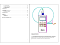
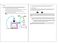
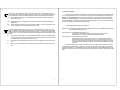
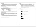
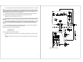
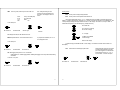
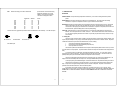
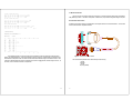
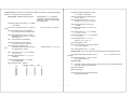
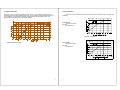
instructions for
TABLE OF CONTENTS
Q-300 NOISE DOSIMETER
1. INTRODUCTION TO THE Q-300 . . . . . . . . . . . . . . . . . . . . . . . . . . . . . . . . . . . . . . . . . . . . . . . . . . . . . . . . . . . . . . . . . . . . .
1.1 Assembling the Meter . . . . . . . . . . . . . . . . . . . . . . . . . . . . . . . . . . . . . . . . . . . . . . . . . . . . . . . . . . . . . . . . . . . . . . .
1.2 Initial Turn On and Check . . . . . . . . . . . . . . . . . . . . . . . . . . . . . . . . . . . . . . . . . . . . . . . . . . . . . . . . . . . . . . . . . . . .
1.3 Calibration . . . . . . . . . . . . . . . . . . . . . . . . . . . . . . . . . . . . . . . . . . . . . . . . . . . . . . . . . . . . . . . . . . . . . . . . . . . . . . . .
Storing the Calibration Value . . . . . . . . . . . . . . . . . . . . . . . . . . . . . . . . . . . . . . . . . . . . . . . . . . . . . . . . . . . . . .
1.4 Battery Installation and Removal . . . . . . . . . . . . . . . . . . . . . . . . . . . . . . . . . . . . . . . . . . . . . . . . . . . . . . . . . . . . . . .
Q300
Noise Dosimeter
2
2
3
4
5
6
2. ABOUT THE METER . . . . . . . . . . . . . . . . . . . . . . . . . . . . . . . . . . . . . . . . . . . . . . . . . . . . . . . . . . . . . . . . . . . . . . . . . . . . . . 7
2.1 The Display . . . . . . . . . . . . . . . . . . . . . . . . . . . . . . . . . . . . . . . . . . . . . . . . . . . . . . . . . . . . . . . . . . . . . . . . . . . . . . . 7
2.2 Keypad Functions . . . . . . . . . . . . . . . . . . . . . . . . . . . . . . . . . . . . . . . . . . . . . . . . . . . . . . . . . . . . . . . . . . . . . . . . . . 8
2.3 Acoustic Event Options . . . . . . . . . . . . . . . . . . . . . . . . . . . . . . . . . . . . . . . . . . . . . . . . . . . . . . . . . . . . . . . . . . . . . 11
2.4 Memory Capacity . . . . . . . . . . . . . . . . . . . . . . . . . . . . . . . . . . . . . . . . . . . . . . . . . . . . . . . . . . . . . . . . . . . . . . . . . 12
2.5 RESET - Erasing Stored Data . . . . . . . . . . . . . . . . . . . . . . . . . . . . . . . . . . . . . . . . . . . . . . . . . . . . . . . . . . . . . . . 12
2.6 Overload Detection . . . . . . . . . . . . . . . . . . . . . . . . . . . . . . . . . . . . . . . . . . . . . . . . . . . . . . . . . . . . . . . . . . . . . . . . 12
2.7 Security . . . . . . . . . . . . . . . . . . . . . . . . . . . . . . . . . . . . . . . . . . . . . . . . . . . . . . . . . . . . . . . . . . . . . . . . . . . . . . . . . 13
Note: Due to the new ATEX Directive in Europe, all references in this document to "Ex" or
"EEx" for intrinsic safety approvals should be disregarded effective 7/1/03 within the
member countries of the European Union (EU). At this time, this product is not approved
in accordance with the new ATEX Directive and is not sold for use in hazardous
atmospheres or explosive zones by customers within the EU. Outside of the EU, all
references to intrinsic safety continue without change.
56-447
Rev. F
8/97
3. SETUP MENU . . . . . . . . . . . . . . . . . . . . . . . . . . . . . . . . . . . . . . . . . . . . . . . . . . . . . . . . . . . . . . . . . . . . . . . . . . . . . . . . . . .
CAL . . . . . . . . . . . . . . . . . . . . . . . . . . . . . . . . . . . . . . . . . . . . . . . . . . . . . . . . . . . . . . . . . . . . . . . . . . . . . . . . .
EVENT . . . . . . . . . . . . . . . . . . . . . . . . . . . . . . . . . . . . . . . . . . . . . . . . . . . . . . . . . . . . . . . . . . . . . . . . . . . . . .
RANGE . . . . . . . . . . . . . . . . . . . . . . . . . . . . . . . . . . . . . . . . . . . . . . . . . . . . . . . . . . . . . . . . . . . . . . . . . . . . .
UL . . . . . . . . . . . . . . . . . . . . . . . . . . . . . . . . . . . . . . . . . . . . . . . . . . . . . . . . . . . . . . . . . . . . . . . . . . . . . . . . . .
CL . . . . . . . . . . . . . . . . . . . . . . . . . . . . . . . . . . . . . . . . . . . . . . . . . . . . . . . . . . . . . . . . . . . . . . . . . . . . . . . . . .
ER . . . . . . . . . . . . . . . . . . . . . . . . . . . . . . . . . . . . . . . . . . . . . . . . . . . . . . . . . . . . . . . . . . . . . . . . . . . . . . . . .
TL . . . . . . . . . . . . . . . . . . . . . . . . . . . . . . . . . . . . . . . . . . . . . . . . . . . . . . . . . . . . . . . . . . . . . . . . . . . . . . . . . .
FAST/SLOW . . . . . . . . . . . . . . . . . . . . . . . . . . . . . . . . . . . . . . . . . . . . . . . . . . . . . . . . . . . . . . . . . . . . . . . . . .
A/C . . . . . . . . . . . . . . . . . . . . . . . . . . . . . . . . . . . . . . . . . . . . . . . . . . . . . . . . . . . . . . . . . . . . . . . . . . . . . . . . .
AO . . . . . . . . . . . . . . . . . . . . . . . . . . . . . . . . . . . . . . . . . . . . . . . . . . . . . . . . . . . . . . . . . . . . . . . . . . . . . . . . .
RT . . . . . . . . . . . . . . . . . . . . . . . . . . . . . . . . . . . . . . . . . . . . . . . . . . . . . . . . . . . . . . . . . . . . . . . . . . . . . . . . . .
BAUD . . . . . . . . . . . . . . . . . . . . . . . . . . . . . . . . . . . . . . . . . . . . . . . . . . . . . . . . . . . . . . . . . . . . . . . . . . . . . . .
EOL . . . . . . . . . . . . . . . . . . . . . . . . . . . . . . . . . . . . . . . . . . . . . . . . . . . . . . . . . . . . . . . . . . . . . . . . . . . . . . . .
FLOW . . . . . . . . . . . . . . . . . . . . . . . . . . . . . . . . . . . . . . . . . . . . . . . . . . . . . . . . . . . . . . . . . . . . . . . . . . . . . . .
TIME . . . . . . . . . . . . . . . . . . . . . . . . . . . . . . . . . . . . . . . . . . . . . . . . . . . . . . . . . . . . . . . . . . . . . . . . . . . . . . . .
PDOSE . . . . . . . . . . . . . . . . . . . . . . . . . . . . . . . . . . . . . . . . . . . . . . . . . . . . . . . . . . . . . . . . . . . . . . . . . . . . . .
LH-0 . . . . . . . . . . . . . . . . . . . . . . . . . . . . . . . . . . . . . . . . . . . . . . . . . . . . . . . . . . . . . . . . . . . . . . . . . . . . . . . .
SE20 . . . . . . . . . . . . . . . . . . . . . . . . . . . . . . . . . . . . . . . . . . . . . . . . . . . . . . . . . . . . . . . . . . . . . . . . . . . . . . . .
SE10 . . . . . . . . . . . . . . . . . . . . . . . . . . . . . . . . . . . . . . . . . . . . . . . . . . . . . . . . . . . . . . . . . . . . . . . . . . . . . . . .
InXX . . . . . . . . . . . . . . . . . . . . . . . . . . . . . . . . . . . . . . . . . . . . . . . . . . . . . . . . . . . . . . . . . . . . . . . . . . . . . . . .
PrnX . . . . . . . . . . . . . . . . . . . . . . . . . . . . . . . . . . . . . . . . . . . . . . . . . . . . . . . . . . . . . . . . . . . . . . . . . . . . . . . .
16
16
16
17
17
17
17
17
17
17
18
18
19
19
19
20
20
20
21
21
21
22
4. COMMUNICATIONS . . . . . . . . . . . . . . . . . . . . . . . . . . . . . . . . . . . . . . . . . . . . . . . . . . . . . . . . . . . . . . . . . . . . . . . . . . . . . .
4.1 Printing Data . . . . . . . . . . . . . . . . . . . . . . . . . . . . . . . . . . . . . . . . . . . . . . . . . . . . . . . . . . . . . . . . . . . . . . . . . . . . .
4.2 Parallel Printer Interface . . . . . . . . . . . . . . . . . . . . . . . . . . . . . . . . . . . . . . . . . . . . . . . . . . . . . . . . . . . . . . . . . . . .
4.3 RS-232 Serial Interface . . . . . . . . . . . . . . . . . . . . . . . . . . . . . . . . . . . . . . . . . . . . . . . . . . . . . . . . . . . . . . . . . . . .
4.4 Downloading Data . . . . . . . . . . . . . . . . . . . . . . . . . . . . . . . . . . . . . . . . . . . . . . . . . . . . . . . . . . . . . . . . . . . . . . . .
4.5 ASCII Commands . . . . . . . . . . . . . . . . . . . . . . . . . . . . . . . . . . . . . . . . . . . . . . . . . . . . . . . . . . . . . . . . . . . . . . . . .
23
23
25
30
31
33
5. GENERAL SOUND MEASUREMENT PRACTICES . . . . . . . . . . . . . . . . . . . . . . . . . . . . . . . . . . . . . . . . . . . . . . . . . . . . . .
5.1 Microphone Positioning . . . . . . . . . . . . . . . . . . . . . . . . . . . . . . . . . . . . . . . . . . . . . . . . . . . . . . . . . . . . . . . . . . . . .
5.2 Accuracy of Readings . . . . . . . . . . . . . . . . . . . . . . . . . . . . . . . . . . . . . . . . . . . . . . . . . . . . . . . . . . . . . . . . . . . . . .
5.3 Microphone Windscreen . . . . . . . . . . . . . . . . . . . . . . . . . . . . . . . . . . . . . . . . . . . . . . . . . . . . . . . . . . . . . . . . . . . .
5.4 Background Noise . . . . . . . . . . . . . . . . . . . . . . . . . . . . . . . . . . . . . . . . . . . . . . . . . . . . . . . . . . . . . . . . . . . . . . . .
35
35
36
36
37
6. TECHNICAL INFORMATION . . . . . . . . . . . . . . . . . . . . . . . . . . . . . . . . . . . . . . . . . . . . . . . . . . . . . . . . . . . . . . . . . . . . . . . 38
6.1
6.2
6.3
6.4
Principles of Operation . . . . . . . . . . . . . . . . . . . . . . . . . . . . . . . . . . . . . . . . . . . . . . . . . . . . . . . . . . . . . . . . . . . . .
Microphone Characteristics . . . . . . . . . . . . . . . . . . . . . . . . . . . . . . . . . . . . . . . . . . . . . . . . . . . . . . . . . . . . . . . . .
Weighting Characteristics . . . . . . . . . . . . . . . . . . . . . . . . . . . . . . . . . . . . . . . . . . . . . . . . . . . . . . . . . . . . . . . . . . .
Tone Burst Response . . . . . . . . . . . . . . . . . . . . . . . . . . . . . . . . . . . . . . . . . . . . . . . . . . . . . . . . . . . . . . . . . . . . . .
38
38
40
41
7. SPECIFICATIONS . . . . . . . . . . . . . . . . . . . . . . . . . . . . . . . . . . . . . . . . . . . . . . . . . . . . . . . . . . . . . . . . . . . . . . . . . . . . . . . . 42
8. ACCESSORIES . . . . . . . . . . . . . . . . . . . . . . . . . . . . . . . . . . . . . . . . . . . . . . . . . . . . . . . . . . . . . . . . . . . . . . . . . . . . . . . . . . 43
8.1 Using The Microphone Boom . . . . . . . . . . . . . . . . . . . . . . . . . . . . . . . . . . . . . . . . . . . . . . . . . . . . . . . . . . . . . . . . 44
8.2 AC/DC Adapter Installation . . . . . . . . . . . . . . . . . . . . . . . . . . . . . . . . . . . . . . . . . . . . . . . . . . . . . . . . . . . . . . . . . . 45
9.0 TROUBLESHOOTING . . . . . . . . . . . . . . . . . . . . . . . . . . . . . . . . . . . . . . . . . . . . . . . . . . . . . . . . . . . . . . . . . . . . . . . . . . . 46
APPENDIX . . . . . . . . . . . . . . . . . . . . . . . . . . . . . . . . . . . . . . . . . . . . . . . . . . . . . . . . . . . . . . . . . . . . . . . . . . . . . . . . . . . . . . . .
Definitions . . . . . . . . . . . . . . . . . . . . . . . . . . . . . . . . . . . . . . . . . . . . . . . . . . . . . . . . . . . . . . . . . . . . . . . . . . . . . . . . . .
Typical Setups . . . . . . . . . . . . . . . . . . . . . . . . . . . . . . . . . . . . . . . . . . . . . . . . . . . . . . . . . . . . . . . . . . . . . . . . . . . . . . .
Acoustical Formulas . . . . . . . . . . . . . . . . . . . . . . . . . . . . . . . . . . . . . . . . . . . . . . . . . . . . . . . . . . . . . . . . . . . . . . . . . .
47
47
50
51
QUEST SERVICE AND WARRANTY POLICY . . . . . . . . . . . . . . . . . . . . . . . . . . . . . . . . . . . . . . . . . . . . . . . . . . . . . . . . . . . . 53
Figure 1. Q-300 Noise Dosimeter.
1. INTRODUCTION TO THE Q-300
The Quest Model Q-300 noise dosimeter performs a wide variety of acoustical measurements. Both exponential
averaged and time integrated measurements may be made, and the results logged in internal memory. The output of an
unweighted peak detector may also be displayed or logged. Applications include industrial, and general acoustical
measurement and analysis. The Q-300 delivers Type 2 accuracy for general field survey work.
1
2
The Q-300 performs the calculations for three dosimeters operating simultaneously in one instrument. A numerical
readout of measurements for any of the three dosimeters may be displayed. The results of individual sound studies may be
stored in internal memory for future reference. Meter operation is controlled from the keypad. Data may be sent to a parallel or
serial printer, or to a computer by using an appropriate interface cable.
The Q-300 may be clipped on a belt or worn in a shirt pocket. The small microphone is simply clipped to the shirt near
the ear. The meters are housed in a tough diecast aluminum case to protect against physical abuse as well as external
electrical interference, such as that from motors or portable radios.
When used with a Personal Computer, the Quest Noise Manager software package allows the user to analyze and print
out pre-recorded data in detail. When used with a printer, the dosimeter can print detailed reports of noise events. It connects
to a printer by using a Quest "Parallel Printer Interface" or "Serial Computer Interface".
1.1 Assembling the Meter
The microphone must be connected to the dosimeter prior to making any measurements. The connector on the top of
the Q-300 is used for both the microphone and the communications interfaces.
To remove the cable connector from the dosimeter, gently grasp and pull the knurled ring of the cable connector.
To attach the cable connector to the dosimeter:
1.)
Grasp the black rubber boot of the cable connector.
2.)
Gently press the cable connector against the dosimeter connector while slowly rotating it. When it is properly
lined up, it will stop rotating and slide into the dosimeter's connector.
Figure 2. Q-300 Cable Connection.
3.) Insert the cable connector until a "click" is heard.
The cable connector is now attached.
1.2 Initial Turn On and Check
Before taking measurements with the Q-300, there is a series of quick checks that should be performed. Turn the unit
on by pressing the ON/OFF key. The display will indicate that a brief warmup is taking place. Check for the LOBAT indicator in
the display. If it indicates a low battery condition, replace the battery.
" on " will appear in the display after warmup. Pressing a FUNCTION key (LEVELS, DOSE, AVG or TIMES) will select
a different display. Press the LEVELS key once, followed by the ª and « keys to review the possible measurements. Pressing
LEVELS again will display data for another dosimeter. Do this for each of the other FUNCTION keys. When you have done
this, press LEVELS and ª or « to set the display to read SPL. The meter is now displaying current Sound Pressure Level,
updating the reading every second.
To perform an Acoustic Study, press RUN/PAUSE. Allow the meter to run for a while and press RUN/PAUSE again to
end the study. The FUNCTION keys may now be used to review the results.
3
4
1.3 Calibration
NOTE: Most calibrators are affected by changes in altitude and barometric pressure. The rated SPL is set at standard
barometric pressure at sea level (760 mm Hg). Consult your calibrator manual for correction factors.
Although the Q-300 will maintain accurate calibration over a long period of time, the calibration should be checked
before each use. To check the calibration of the Q-300, perform the following procedure using a Quest calibrator.
Storing the Calibration Value
1.
Check that the LOBAT indicator is not on, indicating a weak battery.
2.
Turn the calibrator ON. If optional, set the frequency to 1 kHz. Note the SPL of the calibrator. Make sure that
the calibrator output is within the measuring range to which the Q-300 is currently set.
3.
Insert the microphone fully into the calibrator adapter ring, if required for the size microphone in use.
4.
Slowly place the calibrator onto the adapter/microphone.
5.
Press LEVELS. Use the ª or « keys to set the Q-300 to read SPL. The display should read the proper level
within 0.5dB.
The Q-300 can store the time, date and SPL of a calibration, which will be included in the printout and in downloaded
data for each study. If there is data in memory the unit must be RESET prior to performing a calibration (see page 12). To
perform a calibration, enter the following key sequence:
The CAL annunciator in the display will light, and the number in the display should match the output level of the calibrator. (To
change this value, refer to section 3, Setup Menu.) Connect the microphone to the calibrator as directed in steps 2,3 and 4 of
the previous section. Press RUN to begin the calibration routine. The display will read " CAL " and, after a few seconds, return
to the previous CAL display. The calibration SPL, time and date are now stored. If the calibration fails, " FAIL " will appear in
the display.
NOTE: When RUN is pressed to store the calibration value, A weighted SPL and C weighted SPL are measured and set equal
to each other. The unweighted logging peak detector is also calibrated, setting its output at 3dB above the RMS level
shown in the display. The Q300 must be calibrated at a frequency of 1kHz, as this condition is only true at 1kHz (and
6.2kHz).
As the peak detector is most accurate over the upper portion of the range, the calibration value should be in the
upper 40dB of the range used for calibration. It is important to not disturb the microphone during the calibration
routine, as this may cause a high peak reading and result in bad peak data.
The dosimeter will maintain its accuracy for many months of use. However, it is recommended that the dosimeter be
returned annually to a Quest Authorized service station for a recalibration.
Calibration standards, traceable to the National Institute of Standards and Technology (NIST) are maintained and used by
Quest.
Figure 3. Calibrating the Q-300 Microphone Sensitivity.
5
6
1.4 Battery Installation and Removal
2. ABOUT THE METER
The battery must be a 9 Volt alkaline type.
(Examples are: NEDA 1604A, IEC 6LF22, or IEC 6LR61)
2.1 The Display
The LCD display provides the user with the selected measurement and the measurement parameters (A or C weighting,
FAST or SLOW response). Instrument status such as low battery ( LOBAT ), RUN , PAUSE , and Overload ( OL ) is also
displayed.
Replace the battery as follows (see Figure 4):
1.)
Remove the battery cover.
2.)
Lift the non-terminal end of the battery out of the battery compartment.
OL - Overload indicator lights when the sound level exceeds the measurement range of the instrument. While in RUN, this
indicator stays lit until the dosimeter is RESET.
3.)
Remove the battery.
SLOW or FAST - indicates the time response of the measurement being viewed.
4.)
Notice the battery orientation drawing on the battery cover. Be sure that the battery is properly oriented with
respect to the battery compartment terminals.
C, or A - indicates the frequency weighting of the measurement being viewed.
5.)
Angle the non-terminal end of the battery into the battery compartment, and press it down into the holder.
RUN or PAUSE - indicates the operating status of the instrument.
6.)
Install the battery cover.
LOBAT - when not lit, indicates at least 8 hours of battery life remaining.
Figure 5 Q-300 Display
Figure 4. Battery Installation and Removal.
An internal battery powers the clock and memory. When this battery's voltage gets low, data memory and setup will not be
retained when a 9V battery is not in the dosimeter. The memory only draws current from this battery when a 9V battery is not in
the unit. Contact the factory or a Quest service center for replacement.
7
8
2.2 Keypad Functions
Pressing this key turns the meter on. After a warmup period of several seconds, the display will read " on " and the
dosimeter is ready to use. Pressing and holding this key will cause the display to read " OFF5 "and count down for
five seconds until " OFF " is displayed. After this the display will blank and you may release the key. Releasing the
key will turn the meter off. Briefly pressing and releasing this key will toggle the display between " on " and " rES5 "
(Reset), except while in RUN mode when the display will read " run ".
other two.
The LEVELS function key selects the group of items SPL, MAX, MIN or PEAK for display. The ª and « keys are
used to select the specific item. Pressing LEVELS again selects the next dosimeter's (I, II or III) levels for display. If
two or more dosimeters have identical measurement parameters, the higher number dosimeter will not be displayed.
The levels between dosimeters will only differ if the time constant selected for one dosimeter differs from that of the
SPL - Sound Pressure Level (SPL) will be displayed, with the selected weighting and response characteristics. The
value displayed is the maximum SPL during the previous second.
MAX - The Maximum SPL while in the RUN mode is displayed.
Pressing this key begins a study and lights the RUN indicator. Pressing again ends the study and lights the PAUSE
indicator. If the Q-300 is in the setup menu at either CAL or Prn, pressing this key will begin a calibration or start
printing, respectively.
MIN - The Minimum SPL while in the RUN mode is displayed.
PEAK - The Peak Level. The output of the peak detector may be viewed as PEAK or logged. Peak values are the
maximum measured while in RUN mode, except when no RUN time has been accumulated.
The ENTER key is used in the setup menu to begin and end a change of a menu item's value or state. After using
the arrow keys to select a menu item, press ENTER to light the SET indicator, allowing the value to be changed with
the arrow keys. After changing, press ENTER to store the value.
The DOSE function key selects the group of items DOSE, PDOSE or EXP for display. The ª and « keys are used to
select the specific item. Pressing DOSE again selects the next dosimeter's (I, II or III) dose group to be displayed. If
two or more dosimeters have identical measurement parameters, the higher number dosimeter will not be displayed.
The up or down arrows are used to select specific measurements within each of the function displays. For example,
after pressing LEVELS, the arrow keys may be used to select SPL, MAX, MIN or PEAK for display. The arrow keys
are also used to select items in the setup menu, or to set the values for a particular item in the setup menu.
DOSE -
Percentage of allowable sound energy that a person may be exposed to during a work day based on
the criterion level, threshold level and exchange rate selected for the particular dosimeter.
PDOSE -
Projected dose, calculated by assuming the average sound level measured during the run time and
extrapolating to the number of hours selected in the setup menu.
EXP - Sound Exposure in Pascal-squared hours. The display will show " ---- " if the exchange rate is not 3dB.
9
10
2.3 Acoustic Event Options
The AVG function key selects the group of items LAVG, TWA or SEL for display. The ª and « keys are used to
select the specific item. Pressing AVG again selects the next dosimeter's (I, II or III) averages to be displayed. If two
or more dosimeters have identical measurement parameters, the higher number dosimeter will not be displayed.
LAVG - The average level over the study. This measurement takes into account the threshold and exchange rate
entered in the setup menu.
TWA - Time Weighted Average. The average level accumulated during a study, but calculated with an eight hour
integration time.
The Q-300 presents measurement data as follows. Each time that the unit is Run and Paused creates an Event, which
is a set of measurements performed over a user defined period of time, referred to as the Run Time. The event begins at the
Start Time and ends at the Stop Time. Each event is stored in internal memory, with its own data referred to as the Event
Summary. The Overall Summary is the result of all measurements taken since the last RESET. The time between events is
recorded as Pause Time. The Current Event is indicated in the Setup Menu display as " Cxxx " where xxx is the event number.
This is the event initiated the last time the Q300 was placed in RUN.
SEL - The Sound Exposure Level is the constant sound level which, if lasting for one second, would deliver the same
amount of acoustical energy as that accumulated over the entire study.
The TIMES function key selects the group of items RT, PT or UL (Run Time, Pause Time or Upper Limit Time) for
display. The ª and « keys are used to select the specific item, with a minutes:seconds display and an hours display
available for each item. Pressing TIMES again selects the next dosimeter's (I, II or III) times to be displayed, where
UL time may differ. If two or more dosimeters have identical measurement parameters, the higher number dosimeter
will not be displayed.
RT -
The total RUN time will be displayed. Time may be displayed in MIN:SEC and xx:HRS. The MIN:SEC display
for a study that lasts over one hour will wrap around to 00:00. The xx:HRS display will count to 99:Hr and then
wrap around to 00:00 but the actual time will be stored in memory.
PT -
Total PAUSE time since the last time the unit was reset. Pause time is displayed in the same manner as Run
time.
UL -
Upper Limit Time, or the time that the SPL exceeded the Upper Limit Level set for that dosimeter in the setup
menu.
11
An event may be initiated and ended in the following ways:
Manual Event - Press RUN/PAUSE to begin an event, causing the RUN indicator to light. Press RUN/PAUSE again to end the
event, causing the PAUSE indicator to light.
Manual Timed Event - Press RUN/PAUSE to begin an event. If a
Programmed Run Time duration has been set, the event will run for this time duration and
automatically stop. The event may be interrupted by pressing the PAUSE key.
Auto Timed Event - An Auto ON time and date must be set and
enabled in the setup menu and the Q-300 must be turned OFF. When the internal clock/calendar
reaches this time and date, the meter will turn on, warm up for 10 seconds and begin an event. The
duration of the event will be that of the Programmed Run Time stored via the setup menu. At the end
of the event, the unit will PAUSE and turn itself OFF. The event may be interrupted by depressing the
PAUSE key.
Data viewed on the display is normally the Overall Summary Data. SPL is active only while viewing the current event.
In the EVENT portion of the Setup Menu, it is possible to view the data from the current event as it happens, or from previous
events while still in RUN mode. The RUN/PAUSE key may be used to start and stop events while in the EVENT portion of the
Setup Menu. Each time an event is started, the number of that event will briefly appear in the display. Refer to Section 3, Setup
Menu.
12
2.4 Memory Capacity
2.7 Security
The number of events possible is limited by the available memory. Data stored during events also fills memory, so the
length of each event is a factor in determining the total number possible, with longer events using more memory. Data is logged
at a set rate of once every minute. Run time without logging data is limited to 145 hours and 38 minutes. The Q300 will
automatically PAUSE and display " AOL " if this limit is reached. Without logging, a maximum of 300 events is possible.
Maximum logging time is 52 hours.
The Security feature allows you to lock out another person's access to certain dosimeter functions. There are two
security modes, which appear in the Setup Menu as SE1x and SE2x.
SE1 enabled (SE11 in the setup menu display) secures the units controls while it is in the RUN mode. To
unlock the dosimeter, a four digit security code must be entered.
The dosimeter will log the following items:
SE2 enabled (SE21 in the setup menu display) prevents changing any Setup Menu items (except SE1). To
unlock the setup a four digit security code must be entered.
3 LAVGs, 2 LMAXs, 1 Unweighted PEAK
In addition the total amount of energy accumulated during a study is limited. If this limit is reached the Q300 will
PAUSE and display " AOL ". This is dependent upon the range setting and how high the SPLs are during the study. This can
be determined from the value of SEL at various exchange rates as follows:
Exchange Rate
3 dB
4 dB
5 dB
6 dB
SE10 or SE20 in the display indicates that either security function is disabled. To enable either security feature, press
the following keys:
Maximum SEL Without Overflow
129 dB + Range
172 dB + Range
215 dB + Range
258 dB + Range
" On " shown in display
Down Arrow 2 (or 3) times
to SE10 (or SE20) in display
For example, with an exchange rate of 3dB on the 70 - 140 dB range, the maximum SEL without overflow would be 129 dB + 70
dB = 199dB.
2.5 RESET - Erasing Stored Data
SET indicator ON
To erase the data in memory, the Q-300 must be in the PAUSE mode. Press the MENU/ON/OFF key until " rES5 " is
displayed. Press and hold the ENTER key for five seconds. The display will count down from " rES5 " to " rES1 ". After five
seconds the data memory will be cleared, the display will briefly show " ---- ", and " on " will be displayed.
Up or Down Arrow to change
SE10 to SE11 in display
2.6 Overload Detection
While viewing SPL the overload indicator (OL) is displayed whenever the incoming signal saturates (overloads) the
circuitry. If an OL condition occurs while in the RUN mode, the OL indicator will light and remain on for the duration of the study.
"0---" in display
If an overload ocurred, it will be indicated on the hard copy printout. While reviewing an event in memory, the OL
indicator will remain on if an overload occurred during that study.
4x; ª « to set, and ENTER
to enter four digits
Returns to SE11 (or SE21) display
13
14
If SE1 is enabled, after the unit is put into the RUN mode only the arrow and ENTER keys will operate. The display will
read
"0---". Press the arrow keys to set the first digit between 0 and 9. Pressing ENTER moves on to the next digit. After all four
digits have been entered, the unit is no longer secured. If the Q-300 remains in RUN mode, data may be reviewed per normal
operation and the unit resecured by going to the SE10 display in the Setup Menu and pressing ENTER, ª, ENTER. This will
immediately change "SE10" to "SE11" and retain the same security code.
Pausing the dosimeter disables SE1. SE1 must be enabled prior to placing the unit in RUN by going to the SE10
display in the Setup Menu and pressing ENTER, ª and ENTER four more times to keep the same code.
NOTE: SE1 may be disabled with either the SE1 or SE2 code.
Security feature SE1 can be used with Auto-On. An Auto-On time and date may be programmed and SE1 enabled. By
turning the unit off, the Q-300 will turn itself on and RUN at the specified time and date. The unit will be secured during that
RUN period.
If SE2 is enabled the Setup Menus may be reviewed, but not altered, except for enabling or disabling SE1. To disable
SE2, go to the "SE21" display in the Setup Menu and press ENTER. "0---" will be displayed. Enter the four digit code as
instructed above. After successfully entering the last digit the display will return to "SE20" and the setup will no longer be
secured.
Once you have entered the security code, be sure that you don't forget it! If you do, once the unit is placed into the
Secure Mode, you will not be able to disable it unless you know the exact code.
Memorize your codes and, if you wish, record the codes here.
SE1 SECURITY CODE ____ ____ ____ ____
SE2 SECURITY CODE ____ ____ ____ ____
If the code is forgotten, you must do one of the following:
Call Quest at 1-800-245-0779. Quest will provide you with a security code that will allow you to gain access to the Q300.
FAX Quest at 1-262-567-4047. Quest will FAX you a security code that will allow you to gain access to the Security
Function.
Figure 6. Q-300 Flow Diagram
15
16
3. SETUP MENU
To select a different event for review, press the following:
The Setup Menu allows the user to customize the operation of the Q-300. Such parameters as printout content, RS232 communications options, measurement parameters, security options and automatic operation can be selected. These
parameters may only be changed while in PAUSE mode, and measurement parameters may only be changed after the memory
has been cleared (RESET), but contents of the Setup Menu may be reviewed at any time.
To enter the Setup Menu, press MENU/ON/OFF and either the ª or « key to get to either the CAL or PRINT display.
From either display, the ª or « key will step around the Setup Menu. The menu items are discussed below in the order that
they are encountered using the ª key. (Refer to figure 6).
SET indicator on
Measurement Parameters
The calibration display has the CAL indicator turned on and the expected calibration value shown in the display.
If the value in the display is not that of the calibrator being used, this number must be corrected by the following key sequence:
The following group of menu items determines how the measurements are performed for each dosimeter. Each item
may be set differently for each of the three dosimeters, except for RANGE and A/C (frequency weighting) which are set once for
all three dosimeters.
RANGE
Set desired value
SET indicator off
EVENT
The event display will light the EVENT indicator and CXXX will show the current event (the event initiated the last time
the Q300 was placed in RUN), with XXX being the event number. To view the current event, press the following key sequence:
Set to LO (40 - 110dB) or HI (70 - 140dB)
UL
Upper Limit Level; Set level in decibels, 40 to 140
CL
Criterion Level; Set level in decibels, 40 to 140
ER
Exchange Rate; Set to 3, 4, 5 or 6 decibels
TL
Threshold Level; Set level in decibels, 40 - 140
FAST/SLOW
A/C
Desired Data Group
Desired Measurement
SET turns off
Pressing any of the four FUNCTION keys, followed by the arrow keys, will select the desired measurement for display.
Press ENTER to return to the menu. Event data may be reviewed at any time, whether in RUN or PAUSE.
CAL (Refer to section 1.3 for procedure)
SET indicator on
Select event number
Return to Menu
'C' changes to 'r'
Response Time; Set to FAST or SLOW
Frequency Weighting; Set to A or C for all dosimeters
These items are all set in the same manner. When the desired item is displayed, its indicator will be turned on, its value
will be displayed and the dosimeter (I, II or III) will be shown at the bottom of the display.
Return to Menu
To select which dosimeter's parameter is displayed, press:
When the desired dosimeter's value is displayed, press:
SET indicator on
17
18
Set desired value
SET indicator off
Communications Parameters
Auto Run Options
AO
Auto-On Time and Date. Set time and date that the Q-300
will turn on and go into Rmode (after a 10
second warmup). The AO indicator will be
on while viewing or setting this item. Time is
set in 24 hour format, or military time.
RT
Run Time Duration. Set length of time in hours:minutes
to a maximum of 50 hours and zero minutes
that the Q-300 will run following a RUN
command. The RT indicator will be on while
viewing or setting this item. Setting to 00:00
disables this function.
Auto-On time and date has 3 displays to set:
XX:XX (time)
BAUD
Baud rate, or data rate for RS-232 communications. Set
to the same rate as the computer or printer being used. Choices are 300 through 19200 baud or PRLL for
parallel printer operation. These are displayed as follows:
b.300
b.600
b. 1.2
b. 2.4
b. 4.8
b. 9.6
b.19.2
PrLL
dY:XX (day)
o :XX (month)
EOL
300 baud
600 baud
1200 baud
2400 baud
4800 baud
9600 baud
19200 baud
Parallel
End of Line character for data transmission. The choices are displayed as follows:
LF
LFCr
Cr
CrLF
Run Time duration has 1 display to set: XX:XX (time).
To enable, disable or set a value press:
Line Feed
Line Feed + Carriage Return
Carriage Return
Carriage Return + Line Feed
FLOW Flow control (handshaking) option for data communications. This is important for error free transmission of
large amounts of data. The flow control used is XON / XOFF , or software control and should be set the same
on the computer or printer being used. The options are displayed as follows:
SET indicator on
Selects value or OFF
If OFF, SET off.
FLo1
FLo0
If the value was left in the display, pressing enter will blank the minutes. Hours must now be set. Setting one value and
pressing ENTER stores that value and advances to the next value to be set. To set a value press:
Set desired value
Store and go to
To set a value press:
SET indicator on
next value
After setting the last value, the SET indicator will turn off. To review the settings, repeatedly press ENTER without
pressing the arrow keys to advance through the screens.
19
Software control (XON / XOFF)
No flow control
20
Set desired value
SET indicator off
TIME
Time of day, date, month and year are set one item at a
XX:XX
dY:XX
o :XX
199X
Time (24 hour military time)
Day of the month
Month
Year
Security Features
time. Setting and storing one value
advances to the next until all items have
been stored. The displays are shown as
follows:
SE20
Security mode for locking all setup parameters.
SE10
Security mode to lock unit operation while in RUN mode:
The last digit of either display can be a 1 or a 0. 1 indicates that security is enabled, and 0 indicates that security is
disabled. To enable or disable security, change the 0 to a 1, and enter a four digit code using the arrow and ENTER keys. After
correctly entering the last digit, the display will return to the SE11 or SE21 display. See section 2.7, Security, for details. To
enable either security feature, press the following keys: (example shows SE1)
To set a value press:
SET indicator ON
SET indicator on
Set desired value
Store and go to
Up or Down Arrow to change
SE10 to SE11 in display
next value
"0---" in display
After setting the last value, the SET indicator will turn off.
PDOSE Projected dose time. Set to desired number of hours
4x; ª « to set, and ENTER
to enter four digits
for projected dose calculation, from 1 to 18
hours, displayed as XXHr.
Returns to SE11 display
To set a value press:
To disable security, press ENTER at the SE11 or SE21 display. Then enter the code which returns to the SE10 or
SE20 display.
SET indicator on
Set desired value
InXX
SET indicator off
Printout Interval for shortening the printout when
LH-0 Data Logging History turned on or off. LH-0 indicates
logging disabled, LH-1 indicates logging enabled. Disabling data logging saves memory while in RUN, allowing
more Events.
To set LH-0 or LH-1 press:
SET indicator on
SET indicator on
Set desired value
SET indicator off
21
22
Set desired value
SET indicator off
printing logged data, where XX is the number
of minutes of data combined into one data
point. Data is logged at one minute intervals.
Printout Interval may be set to 1, 5, 10, 15,
30 or 60 minutes. To set this value press:
PrnX
Printout mode display, also used to determine the
Logged Data
Prn0
Prn1
Prn2
Prn3
Prn4
Prn5
Prn6
Prn7
Off
On
Off
On
Off
On
Off
On
4. COMMUNICATIONS
printout contents. Choices include turning
logged data and statistics on or off and
whether or not to print event summaries.
The choices are displayed as follows:
Statistics
Off
Off
On
On
Off
Off
On
On
DEFINITIONS
PARALLEL MODE: Data is passed along multiple wires simultaneously. This is used for sending information to parallel
printers.
Events
Off
Off
Off
Off
On
On
On
On
SERIAL MODE: All of the data is passed along a single wire in a sequential stream. This mode is used when sending
information to a computer or serial printers. RS-232 is a type of serial mode communication.
BAUD RATE: Baud rate is the speed at which serial communications take place, measured in bits per second. The baud rate
options for the Q-300 are 300, 600, 1200, 2400, 4800, 9600, and 19,200. The higher the baud rate, the faster the
communication. When trying to pass information from an instrument to a computer or serial printer, both must be set for
the same baud rate. (Baud rate settings have no affect on parallel printing.)
If Events is turned on, logged data is presented for each event rather than for the overall study. To set this value press:
COM PORT: Abbreviated name for a serial communications port on a computer (also called RS232 port). Most PCs have
between 1 and 4 serial ports referred to as COM1, COM2, etc... This is where the cable from the meter connects to the
PC. The COM ports generally will take the form of either a 25 pin male (has pins instead of holes) connector or a 9 pin
male connector.
4.1 Printing Data
SET indicator on
Set desired value
The Q-300 may be connected to either a parallel or serial (RS-232) printer by using the proper cable and adapter. Data
may also be printed directly to a PC by using a communications package such as Procomm or Windows Terminal. The printout
contains the Overall Summary information and individual Events, if desired, including:
SET indicator off
Press RUN to print.
1.
2.
3.
All measurement parameters (Range, Weighting, etc.)
Data Summary of all measured parameters (LEQ, LMAX, etc.)
Start, Stop and Run Times and OL
The information printed will be that selected in the Print portion of the Setup Menu (PRNX - Refer to section 3). See the
end of this section for a sample printout. The printout sections selected in the setup menu are labeled on the sample printout for
clarity.
To connect the Q-300 to a parallel printer, the 056-957 Parallel Interface is required. The 10 pin circular connector
plugs into the jack on the top of the meter. The 36 pin flat cable connector plugs into the printer. The meter must be set for
parallel operation (PRLL option for Baud Rate, located in the Setup Menu - Refer to section 3).
The Q-300 and the printer should all have their power switches turned ON. The meter must be in PAUSE mode. The
display must be set to the PRNX portion of the setup menu. Pressing the RUN/PAUSE key will start the printout.
To interrupt a printout, press RUN/PAUSE again. Disconnect the interface from the printer before turning the Q-300 off.
The Q-300 can be connected to a serial (RS-232) printer or a PC by using the Serial Communications Interface (056956). A 25-pin male to male gender changer will be required for connection to the printer. The printer's communications
parameters must match that of the Q-300. Refer to the following section.
Some printers can work either in serial or parallel mode. The printer must be set up for one or the other. Simply
plugging into the correct connector is not sufficient. Refer to the printer's manual. THE Q-300 HAS A SEPARATE CABLE FOR
CONNECTING TO A PARALLEL PRINTER. THE SERIAL CABLE CANNOT BE ADAPTED TO WORK WITH A PARALLEL
PRINTER.
23
24
4.2 Parallel Printer Interface
General Printer Configuration (Parallel and Serial)
The Parallel Printer Interface is compatible with most Centronics compatible printers. The 056-957 contains electronics which
converts data from the Q-300 into parallel information. The electronics are powered from the Q-300. (An older version of this
cable required its own 9 volt battery.)
Each line of print must end with the following two EOL (End of Line) characters:
LF
CR
(Line Feed)
(Carriage Return)
The EOL (End of Line) characters can be:
Both set within the printer configuration.
Both set within the dosimeter configuration.
One setting within the printer configuration and one setting within the dosimeter configuration.
The dosimeter can be programmed to one of the following four settings:
LF/Cr (Line Feed followed by Carriage Return)
Cr/LF (Carriage Return followed by Line Feed)
LF
(Line Feed only)
Cr
(Carriage Return only)
Figure 7. Parallel Printer Interface.
To try a few lines of print, depress RUN/PAUSE twice. If the printer does not work properly, change the
dosimeter setting until it works.
The Output Format of the Parallel Printer Interface is as follows:
The dosimeter sets up 8 data lines.
If the system still does not print properly, you may need to change the printer setup. Refer to the printer
manual to aid in the printer configuration. After changing the printer setup, it is usually necessary to reset the
printer as follows:
If the Busy line is not high, the dosimeter sends a Strobe pulse.
If the Busy line is high, the dosimeter will wait.
Turn the printer off for a few seconds and then back on. Most printers only read these switches during
the turn on.
Parallel Printer Configuration
The printer must be Centronics compatible.
The dosimeter baud rate does not matter.
If the printer operates in either the Serial or Parallel mode, be sure that it is set to Parallel.
Serial Printer Configuration
Refer to section 4.3, RS-232 Serial Interface.
25
26
SAMPLE PRINTOUT
(EVENT SUMMARY)
(HEADER and OVERALL SUMMARY)
EVENT (1)
Notes ____________________________________________________________________
__________________________________________________________________________
Session Started
18-MAR-95 @ 13:32:45
QUEST TECHNOLOGIES
Q300 NOISE LOGGING DOSIMETER
Unit Version Number: 1.00
DOSIMETER 1
Peak Level
Slow Max Level
Slow Min Level
Serial Number: QC50100005
Name _____________________________________________________________________
Work Area ________________________________________________________________
LAVG
SEL(5)
Comments _________________________________________________________________
Meter Calibration:
114.0dB
Calibrator:
Serial Number ___________________
10-MAR-95 @ 13:06:18
Session Started
18-MAR-95 @ 13:32:45
DOSIMETER 1
Peak Level
Slow Max Level
Slow Min Level
LAVG
SEL(5)
108.5dB
126.2dB
DOSIMETER 2
Peak Level
Slow Max Level
Slow Min Level
LAVG
SEL(5)
109.5dB
126.2dB
DOSIMETER 3
Peak Level
Slow Max Level
Slow Min Level
LAVG
SEL(3)
110.5dB
118.2dB
Session Stopped
18-MAR-95 @ 14:53:21
124.5dB
114.4dB
99.8dB
TWA
Pa2Hr
124.5dB
114.4dB
99.8dB
TWA
Pa2Hr
124.5dB
114.4dB
99.8dB
TWA
Pa2Hr
18-MAR-95 @ 13:32:45
18-MAR-95 @ 13:32:45
18-MAR-95 @ 13:33:18
79.6dB
0.2
DOSE
18-MAR-95 @ 13:32:45
18-MAR-95 @ 13:32:45
18-MAR-95 @ 13:33:18
80.6dB
0.2
DOSE
18-MAR-95 @ 13:32:45
18-MAR-95 @ 13:32:45
18-MAR-95 @ 13:33:18
81.6dB
0.2
LAVG
SEL(5)
Calibration Date ___________________
Measuring Parameters: ( Range 70-140
Weighting A )
DOSIMETER 1
DOSIMETER 2
DOSIMETER 3
Time Constant
SLOW
Time Constant
SLOW
Time Constant
Exchange Rate
5dB
Exchange Rate
5dB
Exchange Rate
Threshold
80dB
Threshold
90dB
Threshold
Criterion
90dB
Criterion
90dB
Criterion
Upper Limit
115dB
Upper Limit
115dB
Upper Limit
DOSE
Run Time
1:21:36
109.5dB
126.2dB
DOSIMETER 3
Peak Level
Slow Max Level
Slow Min Level
SLOW
3dB
80dB
85dB
115dB
LAVG
SEL(3)
110.5dB
118.2dB
124.5dB
114.4dB
99.8dB
18-MAR-95 @ 13:32:45
18-MAR-95 @ 13:32:45
18-MAR-95 @ 13:33:18
TWA
Pa2Hr
124.5dB
114.4dB
99.8dB
79.6dB
0.2
18-MAR-95 @ 13:32:45
18-MAR-95 @ 13:32:45
18-MAR-95 @ 13:33:18
TWA
Pa2Hr
124.5dB
114.4dB
99.8dB
DOSE
80.6dB
0.2
DOSE
18-MAR-95 @ 13:32:45
18-MAR-95 @ 13:32:45
18-MAR-95 @ 13:33:18
TWA
Pa2Hr
81.6dB
0.2
DOSE
Run Time
1:21:36
UL TIME 0:00:00
1.6%
DOSE(12) 1500%
UL TIME 0:00:00
2.6%
DOSE(12) 1556%
UL TIME 0:00:00
4.2%
DOSE(12) 3076%
O.L. Occurred
(LOGGED DATA)
UL TIME 0:00:00
1.6%
108.5dB
126.2dB
DOSIMETER 2
Peak Level
Slow Max Level
Slow Min Level
__________________________________________________________________________
Session Stopped
18-MAR-95 @ 14:53:21
EVENT (1) LOGGING
LAVG 1 (5 MINUTE TIME HISTORY)
DOSE(12) 1500%
13:37
14:02
14:27
14:52
UL TIME 0:00:00
112 114
106 104
124 116
106#
#
117
110
119
#
114
105
106
#
113dB
109dB
117dB
#dB
+----+----+----+----+-- 115dB
+----+----+----+--- 108dB
+----+----+----+----+---- 119dB
+----+83dB#
LAVG 2 (5 MINUTE TIME HISTORY)
2.6%
DOSE(12) 1556%
13:37
14:02
14:27
14:52
UL TIME 0:00:08
4.2%
112 114
106 104
124 116
106#
#
117
110
119
#
114
105
106
#
113dB
109dB
117dB
#dB
+----+----+----+----+-- 115dB
+----+----+----+--- 108dB
+----+----+----+----+---- 119dB
+----+83dB#
LAVG 3 (5 MINUTE TIME HISTORY)
13:37
14:02
14:27
14:52
DOSE(12) 3076%
Page 1
27
28
112 114
106 104
124 116
106#
#
117
110
119
#
114
105
106
#
113dB
109dB
117dB
#dB
+----+----+----+----+-- 115dB
+----+----+----+--- 108dB
+----+----+----+----+---- 119dB
+----+83dB#
4.3 RS-232 Serial Interface
SLOW MAX (5 MINUTE TIME HISTORY)
13:37
14:02
14:27
14:52
114 114
106 104
114 116
106#
#
109
110
119
#
114
105
106
#
113dB
109dB
117dB
#dB
+====+====+==== 114dB
+====+==== 109dB
+====+====+==== 114dB
+====+=
106dB#
The jack on the top of the Q-300 provides direct connection to a computer's COM port with the serial communications
cable (#056-707) provided. To connect to a serial printer or similar device, a 25-pin male to male gender changer is required.
FAST MAX (5 MINUTE TIME HISTORY)
13:37
14:02
14:27
14:52
118 114
106 104
114 116
106#
#
117
110
119
#
114
105
106
#
113dB
109dB
117dB
#dB
Serial Communications Interface
+====+====+====+=== 118dB
+====+==== 109dB
+====+====+==== 114dB
+====+=
106dB#
The Serial Communications Interface is compatible with most Computer COM Ports and most Serial Printers. It converts data
from the Q-300 into RS-232 compatible information.
PEAK (5 MINUTE TIME HISTORY)
13:37
14:02
14:27
14:52
124 114
106 104
120 116
106#
#
117
110
119
#
114
105
106
#
113dB
109dB
117dB
#dB
+====+====+====+====+==== 124dB
+====+====+==== 109dB
+====+====+====+====+ 120dB
+====+=
106dB#
Page 2
(STATISTICS)
% TIME STATISTICAL DISTRIBUTION
Weighting
A
Time Constant Slow
Total Samples
Total Run
156672
1:21:36
dB
99
100
101
102
103
104
105
106
107
108
109
110
111
112
113
114
dB
% Time
0.13%
1.28%
2.57%
15.96%
17.30%
15.74%
5.49%
1.78%
32.43%
4.01%
1.98%
0.69%
0.29%
0.12%
0.10%
0.02%
% Time
Samples
212
2012
4025
25009
27113
24666
8602
2804
50811
6298
3111
1087
460
201
166
37
Samples
0
20
40
60
80
100
+----+----+----+----+----+----+----+----+----+----+
*
*
**
********
*********
********
***
*
*****************
***
*
*
*
*
*
*
+----+----+----+----+----+----+----+----+----+----+
0
20
40
60
80
100
When printing time history, the last row of data may be incomplete due to the study ending prior to the last interval
printed. This will be indicated by #. In the example printout, the data was logged at 1 minute intervals, but combined into five
minute intervals for the printout. Each row contains five five minute intervals and the average for the entire 25 minutes. The #
in the last row indicates that the first value was combined from less than five logging intervals, and the average for the row , for
25 minutes, was from less than 25 minutes of complete data.
29
Figure 8. Serial Communications Interface.
The communications parameters for the ASCII data byte are the following:
1 start bit
8 data bits
1 stop bit
No parity (disabled)
30
Baud rate and flow control must be set the same for both the Q-300 and the RS-232 device connected to it (BAUD and FLOW
as set in the Setup Menu). Refer to section 3 COMM Setup Menu.
There are three common problems when using COM ports.
1.
The ports are often not labelled, making it difficult to determine which port is connected.
2.
The printer output port on the computer is a 25 pin female. Adding an extra 'converter' cable to the
serial cable and plugging it into the printer port will not work.
3.
Often some other device, such as a mouse, is plugged into the COM port. If that is the only COM port
then the mouse must be disconnected and the PC possibly must be reconfigured.
Downloading Using WindowsTM TERMINAL
Microsoft® WindowsTM has a communications program under the ACCESSORIES icon called TERMINAL. Instructions
on how to use TERMINAL are located in the Windows'TM manuals.
Open TERMINAL. For TERMINAL, the communications settings are found by first selecting SETTINGS, then
COMMUNICATIONS. Select the desired COM (serial) port and the baud rate. The baud rate must match the BAUD selected in
the Q-300's Setup Menu. TERMINAL also needs the following information in its setup:
data bits = 8
parity = none
stop bits = 1
flow control = must match the Q-300
To save the downloaded data to a file, use the following procedure. After the communication settings are made:
4.4 Downloading Data
1.
Data stored in the Q-300 may be downloaded to a personal computer. Several methods are available.
The Quest Noise Manager software package provides an easy method of receiving data from the Q-300. Data
presentation options include tabular or graphical form. In addition, remote control and access to all operating parameters is
possible via an easy to use menu driven interface.
By using the RS-232 port on a PC and a communications package such as Procomm or Windows Terminal, the printout
from the meter may be received and stored as a file. The Q-300 must be set for serial operation and the settings (baud rate,
etc.) must match that of the PC. The serial communications cable must be connected between the meter and the PC. Pressing
the PRINT key will cause the meter to print to the PC.
31
32
Select TRANSFERS, then select RECEIVE TEXT FILE.
2.
Enter a file name with the ending .TXT .
3.
Press MENU and « on the Q-300. Prnx will appear in the Q-300's display. Press RUN/PAUSE to print.
4.
When complete, Prnx will disappear from the Q-300's display. Select TRANSFERS, then STOP in the
TERMINAL program.
5.
Exit TERMINAL.
6.
The file has been saved and can be opened with a word processor or editor such as Windows'TM NOTEPAD.
(Remember which directory the file was saved in. The default for Terminal is the WINDOWS directory.)
PRTx enables or disables the programmed run duration.
x = Y for enabled, x = N for disabled.
4.5 ASCII Commands - The following is a list of commands used to setup the Q-300 via RS-232. The display will automatically
switch to the " on " display when commands are being received.
Setup Commands - Duplicates the setup menu functions.
PRTDxx:yy sets the programmed run duration where xx =
hours, yy = minutes.
Omitting parameters w, x, y, or z will return the
current setting. The dosimeter number should be
included. Refer to Section 3.3 for details on setting
the following parameters.
THxyyy sets the integration threshold. x = 1, 2 or 3 for
dosimeter 1, 2 or 3. yyy = 40 to 140, 0 for OFF
AOTx enables or disables Auto On feature. x = Y for enabled,
x = N for disabled.
TIMExx:yy sets the clock where xx = hours (0 to 24),
yy = minutes
AOTSvv:ww:xx:yy:zz sets the auto on time. vv = month, ww =
seconds.
day, xx = hour (0 to 24), yy = minutes, zz =
DATExx/yy/zzzz sets the calendar. xx = month, yy = day,
zzzz = year.
BAUDxxxxx sets the baud rate for serial communications.
xxxxx = 300, 600, 1200, 2400, 4800, 9600 or 19200.
CLxyyy sets the criterion level. x = 1, 2 or 3 for dosimeter
1, 2 or 3. yyy = 40 - 140.
CALxxxx sets the calibration SPL, where xxxx = the SPL of
the calibrator (no decimal point, 1143 = 114.3dB). Set
range is 900 to 1250.
RESPxy sets the response time. x = 1, 2 or 3 for dosimeter 1,
2 or 3. y = F or S.
PRLL
ULxyyy sets the upper limit level. x = 1, 2 or 3 for
dosimeter 1, 2 or 3. yyy = 40 - 140.
sets communications for a parallel printer.
FLOWx enables or disables flow control for RS-232.
x = Y for ON, x = N for OFF or no flow control
where
WGTx sets the weighting. x = A or C.
EOLxx sets the end of line character for serial
communications, either carriage return, line feed or a
RNGx sets the measuring range. x = H for high (70-140dB), or
x = L for low (40-110dB) range
combination of the two. xx = C, CL, L or LC
PTDx sets the Projected Dose Time. x = 1 - 18 (hours)
C = carriage return and L = line feed.
ERxy
Security Commands - Note: Security function SE2 does not affect the ability to change parameters via RS-232.
sets the exchange rate. x = 1, 2 or 3 for dosimeter 1,
2 or 3. y = 3, 4, 5 or 6.
SEyz enables or disables the SEy security feature, where y =
security OFF.
INxx sets the printout interval, where xx = 1, 5, 10, 15, 30
or 60 (Minutes)
SEyzzzz sets the security code. y = 1 for SE1 or 2 for SE2.
zzzz = equals the security code.
LHx enables or disables data logging. x = Y for enabled,
x = N for logging disabled.
Function Commands
PRNx sets the items to print. x = 0 through 7
Prn0
Prn1
Prn2
Prn3
Prn4
Prn5
Prn6
Prn7
Logged Data
Off
On
Off
On
Off
On
Off
On
OFF
Statistics
1 or 2. z = Y for security ON, z = N for
Off
Off
On
On
Off
Off
On
On
Events
Off
Off
Off
Off
On
On
On
On
turns the unit off. Caution: unit cannot be turned on via remote control. Auto On must be enabled with a valid
date and time for the unit to turn on automatically.
PRINT will return the printout.
RESET clears the memory.
FACTORY clears the data memory and resets all setup menu
parameters to factory settings.
33
34
5. GENERAL SOUND MEASUREMENT PRACTICES
Before taking measurements with the Q-300 there is a series of quick checks that should be performed. After switching
the unit ON, check for the LOBAT indicator in the display. Replace the battery if needed.
Although the Q-300 will maintain accurate calibration over a long period of time, the calibration should be checked and
the calibration routine run, if necessary, before each use.
When performing integrating measurements, press the RUN/PAUSE key, making sure " RUN " is indicated in the
display. It is always a good idea to document all measurement conditions and meter settings for possible future needs. If the
data is printed, the settings will all appear on the printout.
5.1 Microphone Positioning
The dosimeter measures sound most accurately without the presence of sound reflecting or absorbing objects. Any
near-by object or surface (including the operator) will act as a reflector or absorber of sound. To minimize these errors, use the
dosimeter as follows:
5.2 Accuracy of Readings
For maximum accuracy, it is important to use the dosimeter correctly and to understand its limitations. It will correctly
integrate all sound levels within the range of the instrument.
A few items related to accuracy are as follows:
There is a tendency to overestimate the accuracy of digital readings. The values (such as Leq) are computed to a
precision of 0.1 dB. However, the absolute accuracy of the reading is not 0.1 dB, but is accurate to the stated overall accuracy
of the instrument.
The 0.1 dB resolution is useful in determining the minimum sample time required to get an accurate short term
measurement.
If, for example, the Leq is increasing 0.3 dB every second, then a longer sample time is required.
When taking Personal Noise Dosimeter Measurements:
If the Leq is remaining stable from second to second within a few tenths of a dB, then the sample time is long
enough.
Connect the Microphone to the shirt at the shoulder. (See Figure 9) Keep it high on the shoulder and away
from the neck if possible.
5.3 Microphone Windscreen
If the noise seems to be coming from one location, place the microphone near the ear facing that location.
Install a Windscreen on the microphone. It holds the microphone in an upright position and keeps the microphone from
brushing against clothing, which can produce high noise levels into the microphone.
It is recommended that a windscreen be used at all times. The Q-300 uses the WS-5 Windscreen. Using a windscreen will
improve the accuracy by minimizing the effect of the following:
Wind blowing across the microphone can produce higher than normal sound level readings. The windscreen blocks
wind from direct contact with the microphone, producing less unwanted noise.
Clothing brushing against the microphone can produce higher than normal sound level readings. The windscreen helps
position the microphone so that clothing cannot brush against it as easily.
Dirt entering the microphone, in time, can damage the microphone, possibly changing the microphone's frequency
characteristics. The windscreen catches and collects this dirt before it enters the microphone.
Simply insert the microphone into the windscreen and gently pull it over the Velcro strip.
5.4 Background Noise
Background noise can cause considerable error in measurement when its level is close to that of the noise source of
interest. When it is not possible to eliminate or reduce the background noise, use the curve shown in Figure 10 to correct for
the effect of the background noise on the measurement.
Figure 9. Placement of Microphone When Used as a Personal Monitor.
When taking Stand-Alone measurements:
Mount the dosimeter to the tripod mount (located on the belt clip) with the microphone upward forming
approximately a 70 degree angle with the noise source.
35
36
The effect of the "Noise Floor" on low level readings can cause inaccurate data. In a "Perfectly Quiet" room, the
electrical noise produced by the microphone is approximately
35 dB on A weighting or 45 dB on C weighting.
6.2 Microphone Characteristics
Measurements must always be at least 5 dB above the "Noise Floor". to be valid. Therefore, the lowest possible
measurements of the dosimeter are approximately:
The Q-300 Noise Dosimeter uses an 8 mm omnidirectional ceramic microphone. It is buffered by a high impedance FET input
stage. (See Figure 12.)
40 dB on "A" Weighting (Lowest Valid Reading).
50 dB on "C" Weighting (Lowest Valid Reading).
6. TECHNICAL INFORMATION
6.1 Principles of Operation
The Q-300 dosimeter uses low power state-of-the-art circuitry. The dosimeter is very stable and reliable over a wide range of
environmental conditions.
The low power circuitry gives the dosimeter a long battery life. When the 9 volt battery is changed, all dosimeter information is
retained due to an internal lithium battery. The lithium battery lasts for many years before needing replacement. (See
SPECIFICATIONS)
A rubber Key Pad is used for all data entry and settings. Menus appear on the display and the keys are used to enter changes.
A block diagram of the Q-300 is shown in Figure 11.
Figure 11. Q-300 Microphone Frequency Response.
Figure 10. Block Diagram of the Q-300
37
38
6.3 Weighting Characteristics
6.4 Tone Burst Response
The Q-300 has "A" and "C" weighting characteristics as shown in Figure 13. For most industrial and community noise
measurement requirements, the "A" weighting should be used. The "A" weighting has a response similar to the human ear.
The "C" weighting is used for measuring noise reduction in hearing protectors and other scientific purposes. Peak
measurements are made with the Linear, or Flat frequency weighting.
Figures 14 and 15 show the meter's tone burst response to sinewave inputs of varied burst duration. The available time
constants are:
SLOW RESPONSE
(1000 msec time constant)
Decay Rate:
4.35 dB per second.
Figure 14. SLOW Response
Figure 13. Weighting Characteristics
FAST RESPONSE
(125 msec time constant)
Decay Rate:
29 dB per second.
Figure 15. FAST Response
39
40
8. ACCESSORIES
7. SPECIFICATIONS
56-963 8mm Shoulder-Mount Dosimeter Microphone, Type 2. One piece system including Cable, Connector, and
Microphone
Standards:
ANSI S1.25 - 1991, ANSI S1.4 - 1983: Type 2
IEC 651 - 1979, IEC 804 - 1985: Type 2
IEC 1252 - 1993
Measuring Range:
40 - 110dB or 70-140dB. Maximum level is for sinusoidal signals. A signal with a 10dB crest factor will
be measured accurately if its RMS level is 10dB below the maximum level for the range. Peak detector
range is 70-114dB or 100-144dB.
Detector:
True RMS, 63dB Pulse Range
Data Output:
Requires Interface Modules connected to the microphone connector.
Parallel operation or Selectable Baud:
300 600 1200 2400 4800 9600 19200.
Microphone:
58-852 Earloops to hold microphone at the ear, package of 10.
56-830 Clothing Clips, package of 5, for microphone cable.
58-452 WS-5 Windscreen, (8mm I.D.), package of 10.
Data Interface Modules
56-957 Parallel Printer Interface, Centronics Compatable
56-707 Serial Communications Interface
25-pin, RS-232 Female
8mm Shoulder-Mount, Type 2. One piece system:
Cable, Connector, and Microphone
56-841 Direct Input Cable for electrical signal input
Printer
Battery:
Single 9-volt alkaline provides approximately 48 hours of operation
Integration Time:
Signal dependent: With a 3dB Exchange rate and a signal level of 140dB the integration time would be
62 hours. As the signal level decreases and the exchange rate increases, the time increases to 145
hours maximum.
56-022 80 Column Parallel Printer, 110 volt only.
Power Supplies
56-973 AC/DC Adapter, inserts into battery compartment.
Uses the MODEL 920 AC Power Supply, not included, or various other power sources.
Memory and Clock/Calendar Battery Backup: Lithium cell, 1 to 2 year life not including time that the 9 volt battery is installed.
o
o
o
o
Temperature:
-10 to +50 C operating; -20 to +60 C storage (battery removed)
Humidity:
0 to 95% non-condensing
Electromagnetic
Field Effects:
Negligible below 50 Oersteds at 50 to 60 Hz.
Tested for RF succeptibility with <1dB error at field strengths to 10 V/m over the frequency range of 10
MHz to 500 MHz.
Size:
5.5 x 2.8 x 1.4 inches (140 x 70 x 40 mm)
Weight:
15.5 oz. (440 grams)
Construction:
Cast aluminum housing with security cover.
56-067 MODEL 920 AC Power Supply, 120 VAC to 9 VDC
QuestSuite for Windows Software
QuestSuite for Windows (3.1 or Windows 95) provides the ability to download data from the Q-300 and
save the data for future reference. Remote setup of measuring parameters, graphing capabilities and
report generation as well as the ability to work with Quest heat stress monitors, gas monitors and
sound level meters make the QuestSuite a valuable tool for industrial hygiene work. Specify the Qseries dosimeter applet for use with the Q-300.
Note: Specifications subject to change.
41
42
8.2 AC/DC Adapter Installation
Quest part number 056-973
Calibrators
056-981
QC-10 Calibrator; 114dB at 1000 Hz Output
056-982
QC-20 Calibrator; Selectable 94dB or 114dB at 250 Hz or 1000 Hz Output
The dosimeter can operate from one of the following power sources if desired:
56-989 Calibrator Adapter, 8 mm to 1 inch coupler.
Fits QC-10 and QC-20.
Any AC power source (9 to 18 VAC, 35 mA minimum)
(Such as the Quest Model 920 AC Power Supply)
58-839 Calibrator Adapter, 8 mm to 1 1/8 inch coupler. Fits older Quest Calibrators models CA-12, CA-15, CA-22
and CA-32.
Any DC power source (12 to 24 VDC, 35 mA minimum)
(The polarity of the DC Plug does not matter.)
Tripods
The power source must have a 3.5mm (1/8") phone plug.
Simply install the AC/DC adapter into the dosimeter battery compartment in place of the battery as follows:
59-045 TP-1 Tripod
Large - will not fit into carrying cases.
Remove the battery from the battery compartment as follows:
59-046 TP-2 Tripod
Small - will fit into some carrying cases.
1.)
8.1 Using The Microphone Boom
The microphone can be mounted on the microphone boom. This makes the dosimeter easier to use when hand-held or tripodmounted.
Connect the microphone to the microphone boom in one of the following ways:
Clip the microphone to the microphone boom.
Unscrew the microphone clip from the microphone and screw the microphone boom to the microphone.
2.)
Carefully wind the cable onto the upper portion of the microphone boom.
3.)
Insert the microphone boom pin into the center hole on the belt clip.
4.)
Fasten the bottom of the microphone boom to the belt clip with the microphone boom thumbscrew.
2.)
Lift the non-terminal end of the battery out of the battery compartment.
3.)
Remove the battery.
Install the AC/DC Adapter as follows:
The microphone boom attaches to the back of the dosimeter as follows:
1.)
Remove the battery cover. (See Figure 4.)
1.)
Position the dosimeter so that the battery compartment is facing upwards.
2.)
Snap the AC/DC adapter into the dosimeter.
3.)
Plug the desired power source (see above) into the AC/DC adapter jack.
The dosimeter is now ready for operation.
Note: Safety approvals for dosimeter use in hazardous locations are for battery operation only. Do not use the AC/DC adapter
in an environment classified as hazardous by the local electrical code or governing agency.
The exposed end of the microphone boom thumbscrew is threaded so that a tripod can be connected to it.
43
44
APPENDIX
9.0 TROUBLESHOOTING
Definitions
Blank display when the ON/OFF key is pressed:
All definitions are in reference to the Q-300 dosimeter.
Replace the battery with a known fresh battery.
BAUD: Baud Rate
The rate of data transfer, in bits per second, between the dosimeter and a printer or computer in the serial output mode.
Unit does not calibrate:
CL:
Check for LOBAT indicator. Battery must check OK.
Check the Calibrator; Listen for a tone from its output.
Criterion Level
The constant sound level in dB that, if applied for 8 hours, would accumulate a DOSE of 100%. (Used in Dose
measurements.)
Reset the dosimeter and try again.
DOSE: Dose
A percentage of the maximum allowable noise that a worker can be exposed to per day. This as a computation that is
based on the following variables: Criterion Level (CL), Lower Threshold (LT), and Exchange Rate (ER).
Try a different microphone if you have another dosimeter. If this works, the microphone needs replacing.
Return for service.
Unit is erratic:
EOL:
End of Line Character
These are printer instructions that can be placed at the end of each line of type in the printout. The dosimeter can be
programmed to send Line Feed (LF) and Carriage Return (CR) instructions.
ER:
Exchange Rate
The number of decibels that a sound must change to either halve or double the rate of dose accumulation.
(3, 4, 5, or 6 dB exchange rates are common.)
Try a different microphone if you have another unit. (The microphone or preamp could be intermittant.)
Return for service.
EVENT: Each measurement time that the dosimeter is in the Run mode.
EXP:
Exposure
A method of measuring dosage, in Pascal Squared Hours. Pa2H is a linear unit rather than a percentage.
1 Pascal is equal to 94 dB. 94 dB for 1 Hour equals 1 Pa2H.
Examples of the 94 dB/time relationship:
94 dB for 1 Hour = 1.00 Pa2H
94 dB for 8 Hours = 8.00 Pa2H
The accumulation of Pa2H will double (or halve) for every 3 dB of change from 94 dB as follows:
97 dB for 1 Hour = 2.00 Pa2H
94 dB for 1 Hour = 1.00 Pa2H
91 dB for 1 Hour = .50 Pa2H
88 dB for 1 Hours = .25 Pa2H
85 dB for 1 Hours = .125 Pa2H
1 Pa2H is typically the maximum allowable Exposure.
45
46
85 dB for 8 Hours = 1 Pa2H
maximum value (Slow or Fast Response) for the previous 1 second period.
FAST: Fast Response
A Measurement Time Constant, or averaging time, of 125 milliseconds. When Fast is used, SPL will closely track a
fluctuating noise source.
STATISTICS: % Time Statistical Distribution
For a given run time, the percentage of time that a sound level occured at a specific dB level.
LAVG: Average Level
The average sound level, in decibels, for the measurement period based on either a 4, 5, or 6 dB Exchange Rate (ER).
If the Exchange Rate (ER) is 3 dB, then LAVG becomes LEQ.
TIME HISTORY: Time History
A Printout list (and Graph) showing how levels were accumulated over time. A printout can be made for each of the
following: Lavg, Lmax, and Peak.
TL:
LEQ: Equivalent Continuous Sound Level
The average sound level for the measurement period based on a 3 dB Exchange Rate (ER).
If the Exchange Rate (ER) is 4, 5, or 6 dB, then LEQ becomes LAVG.
TWA: Time Weighted Average
The sound level in decibels that is accumulated for any time period but with its average level computed over an 8 hour
time period.
MAX: Maximum Level
The highest sound pressure level, in decibels, that occurs during a given time period.
MIN: Minimum Level
The lowest sound pressure level, in decibels, that occurs during a given time period.
#
If the time period is less than 8 hours, the Time Weighted Average will always be less than the Average Sound
Level (LAVG).
#
If the time period is more than 8 hours, the Time Weighted Average will always be more than the Average
Sound Level (LAVG).
TWA is usually measured with A Weighting, Slow Response, and a 5 dB Exchange Rate. However, the dosimeter will
allow A or C-Weighting, Slow or Fast Response, and a 3, 4, 5, or 6 dB Exchange Rate.
PEAK: Absolute Unweighted Peak
The highest instantaneous sound pressure, in decibels, that occurs during a given time period.
UL:
PDOSE: Projected Dose
A percentage computed by measuring dose for some time period and extrapolating it to a different time period.
(Example: 50% Dose / 4 hrs = 75% Projected Dose / 6 hrs)
SEL:
Threshold Level
A preset level in decibels below which sound is not accumulated or averaged into LAVG, LEQ, or Dose.
Upper Limit Time
The total time that the sound level exceeds a preset level.
Typical Setups
OSHA NOISE COMPLIANCE
Sound Exposure Level
The constant sound level in decibels which, if lasting for one second, would deliver the same amount of acoustical
energy as that delivered over the entire measurement period.
Threshold = 90dB
Weighting = A
SEL is usually measured with a 3 dB Exchange Rate. However, the dosimeter will also allow SEL to be measured with
4, 5, or 6 dB Exchange Rates. On a printout, the exchange rate is shown in parenthesis.
Exchange Rate = 5dB
Response = Slow
OSHA HEARING CONSERVATION
Same as above except with Threshold = 80dB
SLOW: Slow Response
A Measurement Time Constant, or averaging time, of 1 second. When Slow is used, SPL will not track a quickly
fluctuating noise source, but will produce an averaged reading.
DEPARTMENT OF DEFENSE NOISE COMPLIANCE
SPL:
IEC NOISE MONITORING
Threshold = 80dB
Weighting = A
Sound Pressure Level
A quantity in decibels equal to the sound pressure divided by 20 uPa (0.00002 N/m2), times 20. The word "Level"
indicates that the sound pressure is a certain level above the reference level. The SPL is displayed each second as the
47
Threshold = OFF
Weighting = A
48
Exchange Rate = 4dB
Response = Slow
Exchange Rate = 3dB
Response = Slow
Acoustical Formulas
The Q-300 uses the following formulas to calculate the accumulated data:
Where:
LS
=
Sound Level in dB with the selected Time Constant (Slow or Fast). Its value is entered only if the Sound Level
is greater than the Threshold Level. Otherwise, it is entered as minus infinity.
TC
=
8 Hour Criterion Time. Enter 28800 seconds.
RTIME =
Run Time in seconds.
ER
=
Exchange Rate in dB. (Selectable 3, 4, 5 or 6 dB)
CL
=
Criterion Level in dB. (Selectable 40 to 140 dB)
LHIST =
Integrated Level stored either in 1 second, 10 second, or 1 minute periods based on the programmed Logging
setup.
HTIME =
Time (in seconds) used to compute Time History. (Selectable: 1 second, 10 seconds, or 1 minute.)
SC
= Sample Counts. The number of samples occurring at the same dB level.
TS
= Total Samples. The total number of samples during the Run Time.
Prt
=
Projection Time in seconds.
For definitions of the following:
DOSE
PrD (Projected Dose)
TWA
% TIME STAT DIST
ER
See APPENDIX, Acoustical Definitions.
49
50
CL
LEQ
Pa H (Exposure)
2
LAVG
SEL
QUEST SERVICE AND WARRANTY POLICY
Service Policy
The Quest product you have purchased is one of the finest acoustic instruments available. It is backed by our full one
year warranty which seeks complete customer satisfaction. This is your assurance that you can expect prompt courteous
service for your equipment from the entire Quest service organization.
Should your Quest equipment need to be returned for repair or recalibration, please contact the Service Department at
1(800)245-0779 (USA) or Fax (262)567-4047 for a Return Authorization Number. The RA number is valid for 30 days, and must
be shown on the shipping label and purchase order/cover letter. If you are unable to return instruments in that time call for a
new RA number. Send it prepaid and properly packed in the original shipping carton directly to Quest Technologies,1060
Corporate Center Dr., Oconomowoc, WI 53066 U.S.A..
Repair or replacement work done under warranty will be performed free of charge, and the instrument will be returned
to you prepaid. Your copy or a photocopy of the Quest Registration Card will serve as proof of warranty should the factory
require this information.
If for any reason you should find it necessary to contact the factory regarding service or shipping damage, please direct
your calls or letters to the attention of the Service Manager, Quest Technologies, (262) 567-9157 or (800) 245-0779. Office
hours are from 8 AM to 5 PM (Central Standard Time) Monday through Friday.
Warranty
Quest Technologies warrants our instruments to be free from defects in materials and workmanship for one year under
normal conditions of use and service. For U.S.A. customers we will replace or repair (our option) defective instruments at no
charge, excluding batteries, abuse, misuse, alterations, physical damage, or instruments previously repaired by other than
Quest Technologies. Microphones, sensors, printers and chart recorders may have shorter warranty periods. This warranty
states our total obligation in place of any other warranties expressed or implied. Our warranty does not include any liability or
obligation directly resulting from any defective instrument or product or any associated damages, injuries, or property loss,
including loss of use or measurement data.
For warranty outside the U.S.A., a minimum of one year warranty applies to the same limitation and exceptions as
above with service provided or arranged through the authorized Quest sales agent or our Quest European Service Laboratory.
Foreign purchasers should contact the local Quest sales agent for details.
51