1
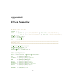
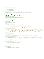
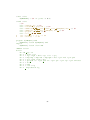
nRF2400 Set one node as RX and one as TX and try to make them communicate
The tests should be performed in the following order:
The test sets the Bus-Switches (MUX) to point towards the AVR at boot-up. If this fails, the
UART1 LED’s will not function.
5.1.1
Fuse programming
The fuse setup particular features of the ATMega (see section 4.1.1).
1. Use UISP to program fuses
5.1.2
Program upload
Test the program upload port (AVR-UART0, AVR→PEN).
1. Test that the PEN (program enable) and the UART0 (RXD0/RXD1) pins are connected and
working.
2. Connect the HoghthrobV0 comm port to the STK500 ISP.
3. Upload anything to the Flash and read it back using USIP (on Linux) The test patterns are:
0’s, 1’s and alternating 1’s and 0’s.
4. The uploaded and the downloaded programs should be the same.
A simple way to test this is simply to test this is to supply uisp with the “–verify” option:
uisp --verify -dprog=stk500 -dserial=/dev/ttyUSB0 -dpart=ATmega128 -v=2 --erase
--upload if=build/hogthrobV0/main.srecb
5.1.3
ATMega UART1
Test the connection to the secondary UART (AVR-UART1)
1. Test that the Rx and the Tx lines are connected to the Pin Header (Radio IO). Test the
buffer (NC7SX125) and the control line (Radio IO11 → PC11)
2. Connect RXD1/TXD1 on the Radio Connector to the PC via RS232 level- converter (on
STK500). Upload the test program to the AVR. Start MiniCom terminal emulator on PC
(with Linux) or a similar program with Windows (Hyperterminal). Local echo should be
disabled in the terminal emulator. The control line for NC7SX125 is set ’High’ and the
resistor R37 is unmounted (if mounted).
3. Each typed character should be echoed back immediately.
5.1.4
ATMega LED
Test connection to LEDs (D0 on motherboard and D0/D1 on radio board)
1. Test that the LED’s on the MB (LED → PD7) and on the Radio Board (RADIO IO7/RADIO IO8
→ PC3/PG4) are working
2. Start the blink test in the test program
3. See the LED’s blinking
28