1
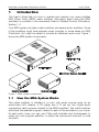
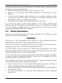
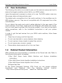
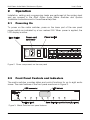
Multi Room Audio
Matrix Switcher and System
560884/2E
560884/2
User’s Guide
Multi Room Audio Matrix Switcher and System
User's Guide
Contents
1
2
3
4
5
6
7
Introduction
1.1
How the MRA System Works
1.2
Safety Information
1.3
Care Instructions
1.4
Related Product Information
Operation
2.1
Powering On
2.2
Front Panel Controls and Indicators
2.3
Selecting a Program for an Audio Zone
2.4
Streaming Audio
2.5
Annunciation (Optional)
2.6
Broadcast Audio (Optional)
Rear Panel Features
Troubleshooting
4.1
Replacing the Fuse
Specifications
Standards Complied
Two-Year Warranty
3
3
4
5
5
6
6
6
7
8
8
8
9
11
12
13
14
15
The information in this manual is provided in good faith. Schneider Electric endeavours to ensure the
relevance and accuracy of the information, but assumes no responsibility for any loss incurred as a
result of its use. Schneider Electric does not warrant that the information is fit for any particular
purpose, nor does it endorse its use in applications that are critical to the health or life of any human
being. Schneider Electric reserves the right to update the information at any time without notice.
January 2010
2
Multi Room Audio Matrix Switcher and System
1
User's Guide
Introduction
This User's Guide tells you how to operate and maintain your newly installed
Multi Room Audio (MRA) matrix switcher. Information about using the MRA
amplifiers is provided in the documents listed in Related Product Information,
Section 1.4.
Your MRA system includes a matrix switcher and several audio amplifiers. Some
of the amplifiers might have external power supplies. In some cases an MRA
Distribution Unit might be added to provide an additional audio input. Figure 1
shows the MRA system components.
Figure 1. MRA system components
1.1
How the MRA System Works
The matrix switcher is installed in a room with audio sources such as an
audio/video (A/V) receiver, a CD player and a TV set top box. Digital audio
connections send program material to the MRA amplifiers. The matrix switcher
distributes the selected program material to each of the amplifiers in your home.
At each audio zone, you can use C-Bus wall switches and touchscreens to
make your own program selection, to adjust the volume and tone and to mute
the audio.
3
Multi Room Audio Matrix Switcher and System
User's Guide
The matrix switcher is the control centre for your MRA system. Using the matrix
switcher you can do the following:
• Select a music program for any audio zone in your home.
• Select any of the preset radio station selections for distribution to audio
zones.
• If you have the deluxe matrix switcher, you can send streaming audio
programs to the audio zones from a variety of sources, including a local
area network (LAN), or a USB memory stick.
• Connect a music player to the matrix switcher's front panel.
If you have the deluxe model matrix switcher, a PC running C-Bus Ripple
software controls the streaming audio feature using your LAN (refer to Section
2.4). Your system integrator will set up the program on your PC and you can
access the application Help files as needed.
1.2
Safety Information
Improper use of the equipment could cause serious injury. Please pay close
attention to the following warnings.
WARNINGS
There are no user serviceable parts inside the matrix switcher enclosure.
Replacing the fuse does not require opening the unit cover.
Use only the power cord supplied with the unit to connect to the mains supply.
Using the wrong power cord could cause electrical shock.
Do not let water or other liquids drip or splash onto the equipment. You could
receive an electric shock. If a spill occurs, unplug the power plug from the power
outlet immediately and call your system installer.
Do not cover the unit or block the vent holes on the matrix switcher, amplifiers,
or power supplies. Inadequate ventilation could result in overheating and the
possibility of injury due to fire or smoke.
The amplifiers can produce sounds loud enough to cause permanent hearing
loss. Prevent hearing loss by doing the following:
•
•
•
4
Keep volume controls at low levels when selecting program sources or
when connecting local audio sources to an MRA amplifier.
Plug the headphones into the MRA amplifier before placing the earpieces on
your head or in ears.
Do not allow children to use the MRA equipment without adequate
supervision.
Multi Room Audio Matrix Switcher and System
1.3
User's Guide
Care Instructions
The following information is provided to give you the maximum enjoyment and to
ensure the longest possible product life for your MRA system.
Leave the equipment powered on when not in use. The MRA system uses very
little power when not being actively used.
The digital audio connections from the matrix switcher to the amplifiers are for
MRA system use only. They are not compatible with A/V equipment from other
manufacturers.
Do not disturb the audio and control cables attached to the rear panel of the
matrix switcher. The C-Bus, digital audio and Ethernet LAN cables look similar,
but you must never plug them into the wrong sockets. If you are not sure about
cable connections, refer to the Installation Instructions or call your system
installer.
In order to get the best service from your MRA matrix switcher, follow these
guidelines:
•
Clean the unit using a soft lint free cloth.
•
Do not use chemicals or spray cleaners when cleaning.
•
Do not use hard, sharp objects to select the controls.
•
Do not remove any covers or panels.
•
Place cables where people will not trip over them.
1.4
Related Product Information
MRA software and documentation is available at the Clipsal web site. Refer to
the following documents, as needed.
C-Bus Multi Room Audio Matrix Switcher and System Installation
Instructions
C-Bus Multi Room Audio Amplifier Installation Instructions
C-Bus Multi Room Audio Amplifier User's Guide
Software Help files
At the Clipsal Integrated Systems (CIS) Portal you can access software
downloads and
literature.
Visit the
following
Internet
location:
http://www.clipsal.com/cis/portal Select the 'Technical' area.
5
Multi Room Audio Matrix Switcher and System
2
User's Guide
Operation
Installation, cabling and programming tasks are performed at the system level
and are covered in the Multi Room Audio Matrix Switcher and System
Installation Instructions and in the software Help files.
2.1
Powering On
To power on the matrix switcher, press on the lower part of the rear panel
power switch as indicated by a box marked ON. When power is applied, the
LCD display is active.
Figure 2. Power components on the rear panel
2.2
Front Panel Controls and Indicators
The matrix switcher provides status and control functions for up to eight audio
zones. The main features of the front panel are shown in Figure 3.
Figure 3. Matrix Switcher front panel features
6
Multi Room Audio Matrix Switcher and System
User's Guide
Connection
/Indicator
Description or Function
LCD screen
Shows the program selection choices. Pressing a Zone
selection button displays the name and input source of the
zone. If one or more internal tuners are configured, the
active radio station(s) along with the approximate signal
strength will be displayed on this screen.
Zone selection
pushbuttons
The eight pushbuttons allow you to select the audio
program for each connected audio zone. Pressing the
button again within 8 seconds selects the next input source
and routes it to the zone.
USB socket
1 – Type A
Lets you play MP3 files from a device such as a USB drive
using the streaming audio feature on the deluxe matrix
switcher. The front USB port operates independently from
the USB socket located on the rear panel.
AUX
(3.5 mm stereo jack)
This socket lets you connect an audio source, such as a
portable audio player. The AUX socket is electrically
connected to Source Input 4 at the back of the unit. If you
are using the front panel AUX socket, do not attach cables
to Source Input 4 at the rear panel.
Table 1. Front Panel switches and indicators
2.3
Selecting a Program for an Audio Zone
In a typical MRA system installation, there are several ways to change a zone’s
input source. You can do this by using:
•
•
•
•
a zone selection button on the Matrix Switcher
the Source selection buttons on a Desktop Amplifier
an infrared (IR) remote control used with a Desktop Amplifier
an appropriately configured C-Bus wall switch or touch screen.
Figure 4. Selecting a program source for a Zone
7
Multi Room Audio Matrix Switcher and System
2.4
User's Guide
Streaming Audio
If you have a matrix switcher that supports audio streaming, you can send
program material to the audio zones using an Ethernet LAN connection or a
USB thumb drive at the front panel USB port. Use C-Bus Ripple software to
manage streaming content.
Note:
The USB socket on the back panel is provided for setup and configuration
purposes. It is not used as an audio input.
2.5
Annunciation (Optional)
The matrix switcher has the capability of announcing the name of an input
source whenever it is selected. Annunciation provides instant feedback when
changing the source selection using a C-Bus switch, amplifier or remote control.
Annunciation is broadcast through the speakers in the zone where the input
source has changed. Using MARPA configuration software, the installer can
disable this feature.
2.6
Broadcast Audio (Optional)
The matrix switcher includes two broadcast inputs: one high priority (labelled HI)
and one low priority (labelled LO). These inputs allow a mono input such as a
doorbell, telephone extender or alarm to be broadcast throughout the MRA
system.
Figure 5. Broadcast Audio input and adjustment locations
The following actions may vary depending on how the installer has configured
the matrix switcher.
•
8
Audio connected to the low priority input is broadcast at the currently set
volume, to all amplifiers that are switched on and have Source Input 1, 2, 3
or 4 selected.
Multi Room Audio Matrix Switcher and System
User's Guide
•
The installer uses MARPA configuration software to set the volume of the
audio connected to the high priority input that is broadcast to all amplifiers.
•
Any amplifiers in standby mode are switched on to ensure the audio is
broadcast as widely as possible. Five seconds after the broadcast audio
ceases, amplifiers return to standby (if applicable) and to the previously set
volume.
•
A high priority (HI) broadcast uses left and right channel speakers. A low
priority (LO) broadcast uses right channel speakers only. Audio connected
to a high priority broadcast input must be of sufficient volume to trigger a
broadcast.
3
Rear Panel Features
The installer normally completes rear panel connections for you. If you need to
check a connection to the rear panel, use Figure 6 and Table 2 for reference.
Many network cables appear similar but have different electrical properties. You
can damage your equipment by plugging a cable into the wrong port. If you are
not absolutely sure about connecting cables, consult your system installer.
Figure 6. Matrix Switcher rear panel connections and indicators
Connection
/Indicator
Description or Function
Power switch
Switches the unit on and off.
Power cord
connector
Connect the power cord here to power the matrix switcher. The
matrix switcher also provides power for connected amplifiers
that do not have an external power supply.
IR OUT
2 – 3.5 mm
These 3.5 mm sockets connect to IR Emitter leads. IR Emitters
are then coupled to IR receivers on A/V equipment to provide
remote control from any zone.
9
Multi Room Audio Matrix Switcher and System
User's Guide
BROADCAST inputs
2 – RCA
Line level mono audio that is connected here is broadcast to all
zones that have an analogue input source selected. Refer to
Section 2.6.
HI/LO adjustment
2 – trimpots
These adjust the level of the audio source connected to the
mono broadcast inputs. Use a small Phillips screwdriver to
rotate the control if the audio source is too quiet or loud.
USB
1– Type B
This connection is used for programming the matrix switcher
during commissioning by the installer using a PC running
MARPA configuration software.
LAN
1 – RJ45
This RJ45 socket enables connection to a local (computer)
network for the streaming functionality of the deluxe matrix
switcher.
OPTICAL
IN/OUT
Used to connect a digital optical audio source for distribution to
any of the eight zones. The digital audio format must be 44.1 or
48 kHz stereo. Some digital audio formats (such as surround
sound) are not compatible with the Matrix Switcher. The optional
output is provided so that the input can be sent on to another
piece of A/V equipment. You cannot use the optical input and
the DIGITAL AUDIO IN at the same time.
DIGITAL AUDIO
OUT
8 – RJ45
Each zone output is used to connect the matrix switcher to one
amplifier in each audio zone.
DIGITAL AUDIO
IN
1 – RJ45
Use this connection when using an optional MRA Distribution
Unit to provide an additional stereo audio input.
SOURCE INPUT
4 – RCA pairs
Most A/V devices connect to the matrix switcher through the
four standard stereo analogue inputs. These are line level RCA
sockets are numbered 1 through 4. Input 4 electrically tied to
the front panel AUX connector. This input should be used as
either a line-level input (rear panel) or a headphone-level input
(AUX input), not both.
AM/FM antenna
1 – Type-F coaxial
One antenna connection serves both internal AM/FM tuners.
C-Bus
2 – RJ45
There are two connections for the C-Bus network to allow for
looping through to additional pieces of equipment.
Unit indicator and
C-Bus indicator
Unit and C-Bus indicators show network status and activity.
Refer to Section 2.3 for indicator functions.
Table 2. Matrix Switcher rear panel connections and indicators
10
Multi Room Audio Matrix Switcher and System
4
User's Guide
Troubleshooting
Symptom
Possible Explanation
There is no sound after switching
the amplifier on (sound worked
previously).
The volume may have been set to minimum,
or the amplifier may have been muted (on a
desktop amplifier) before the amplifier was
switched off.
The default volume, bass or treble
settings have changed (when
switching the amplifier on).
If a power failure occurs when the amplifier is
on, the volume, bass and treble settings are
saved and become the new defaults.
Unexpected behaviour occurs
after the digital zone connections
are changed.
The amplifier’s zone settings are not reset
until all power is removed from the amplifier.
Alternatively, use the Reset Amplifier function
on the unit’s C-Bus Status tab in Toolkit.
The wrong amplifier is responding
to source changes.
The “Use Matrix Switcher auto assigned
zone” option may not be enabled. This
option is in the amplifier’s Zoning tab in
Toolkit. After changing the status of this
option (on a live network), use the Reset
Amplifier function on the C-Bus Status tab.
The matrix switcher no longer
responds to button presses.
Turn the matrix switcher off for several
seconds, then on. Use the power switch on
the rear of the matrix switcher, next to the
power cord socket.
The matrix switcher does not
power up.
The fuse may need replacing. Remove the
power cord from the power outlet before
replacing the fuse.
A mains circuit breaker trips when
amplifiers are powered up.
This may occur if more than five amplifier
power supplies are connected to the same
circuit, due to a high inrush current.
An
amplifier
switches
off,
particularly when the volume is
loud.
If insufficient current is available for the
amplifier, it will switch itself off. This may
occur if the amplifier receives its power from
a matrix switcher. The amplifier may need its
own external power supply unit.
11
Multi Room Audio Matrix Switcher and System
User's Guide
Symptom
Possible Explanation
Dynamic labels don’t work on a
C-Bus DLT wall switch.
There are several options that need to be
selected for labels to function. These options
are located:
on the More panel accessed by clicking the
“More....” button on the amplifier’s C-Bus
Control tab in Toolkit.
on the DLT wall switch’s Global tab in
Toolkit.
on the Zones branch of the Project tree in
MARPA.
An amplifier emits a high-pitched
screeching
sound
when
a
particular source is selected.
This may occur if an output of an amplifier is
connected to the input of the matrix
switcher. Such a connection should be
avoided as it can cause a feedback loop.
Audio is not broadcast via the
matrix switcher’s high priority (HI)
broadcast input.
The level of the audio connected to the
broadcast input may not be sufficient to
trigger the broadcast.
Cannot hear any sound when
using the optical input
The digital audio source may be connected
to the optical output instead of the input (on
a matrix switcher). Some digital audio
formats (such as surround sound) are
incompatible with the MRA system.
Table 3. Troubleshooting symptoms and possible causes
4.1
Replacing the Fuse
A replaceable fuse is installed in the fuse holder that is part of the AC inlet
connector on the rear panel of the matrix switcher. Other than the fuse, there
are no other user serviceable parts inside the matrix switcher. If fuse
replacement is required, always use the correct fuse listed on the rear panel.
When replacing the fuse, you must (1) power off the matrix switcher and (2)
remove the power cord before opening the fuse holder. And then (3) replace the
fuse with the correct type and rating as described on the rear panel.
12
Multi Room Audio Matrix Switcher and System
5
User's Guide
Specifications
Matrix Switcher
Parameter
Description
Supply Voltage
220 – 240 V a.c.
Mains frequency range
47 to 53 Hz and 57 to 63 Hz
Power consumption
220 VA maximum
C-Bus network voltage
15 to 36 V d.c.
C-Bus sink current
22 mA; the matrix switcher does not supply
current to the network
C-Bus AC input impedance
80 kΩ @ 1 kHz
Network clock and burden
Software selectable
Source input signal level
2.8 V p-p maximum (47 k Ω)
A/D conversion
16 bit PCM
Operating temperature
10 to 40 °C (50 to 104 °F)
Operating humidity
10 to 90% RH (non-condensing)
System Audio Output Specifications
Parameter
Description
Frequency response
40 Hz to 20 kHz (+2.4 dB / -0.75 dB)
Total harmonic distortion
(1 kHz, 20 W RMS into 4 Ω)
0.16% at 1 kHz, 20 W RMS into 4 ohms
Signal to noise ratio
> 63 db (peak, unweighted)
13
Multi Room Audio Matrix Switcher and System
6
User's Guide
Standards Complied
DECLARATIONS OF CONFORMITY
The 560884/2 and 560884/2E MRA Matrix Switchers comply with the following:
Australian/New Zealand EMC & Electrical Safety Frameworks and Standards
Regulation
Standard
Title
Electrical Safety *
AS/NZS 60065
Audio, video and similar electronic
apparatus - Safety requirements
EMC
AS/NZS CISPR 22 Information technology equipment - Radio
disturbance characteristics (emissions)
European Directives and Standards
European Council
Directive
Standard
Title
2006/95/EC LVD
EN 60065
Audio, video and similar electronic
apparatus – Safety requirements
2004/108/EC
EN 55022
Information technology equipment – Radio
Disturbance Characteristics – Limits and
Methods of Measurement
EN 55024
Information technology equipment –
Immunity Characteristics – Limits &
Methods of Measurement
2002/95/EC RoHS
Reduction of hazardous substances
Other International Directives and Standards
14
Directive
Standard
Title
2004/108/EC
CISPR 22
Information technology equipment – Radio
Disturbance Characteristics (emissions)
CISPR 24
Information technology equipment –
Immunity Characteristics
IEC 60065
Audio, video and similar electronic
apparatus – Safety requirements
Multi Room Audio Matrix Switcher and System
7
User's Guide
Two-Year Warranty
The Multi Room Audio System Products carry a two-year warranty against
manufacturing defects.
Warranty Statement
The benefits conferred herein are in addition to, and in no way shall be deemed to
derogate; either expressly or by implication, any or all other rights and remedies in
respect to the Schneider Electric product, which the consumer has in the location where
the product is sold.
The warrantor is Schneider Electric with offices worldwide.
This Schneider Electric product is guaranteed against faulty workmanship and materials
for a period of two (2) years from the date of installation.
Schneider Electric reserves the right, at its discretion, to either repair free of parts and
labour charges, replace or offer refund in respect to any article found to be faulty due to
materials, parts or workmanship.
This warranty is expressly subject to the Schneider Electric product being installed, wired,
tested, operated and used in accordance with the manufacturer's instructions. Any
alterations or modifications made to the product without permission of Schneider Electric
might void the warranty.
Schneider Electric shall meet all costs of a claim. However, should the product that is the
subject of the claim be found to be in good working order, all such costs shall be met by
the claimant.
When making a claim, the consumer shall forward the Schneider Electric product to the
nearest Schneider Electric office. Provide adequate particulars of the defect within 28
days of the fault occurring. The product should be returned securely packed, complete
with details of the date and place of purchase, description of load, and circumstances of
malfunction.
For all warranty enquiries, contact your local Clipsal sales representative. The
address and contact number of your nearest sales office can be found at
http://www.clipsal.com/locations or by telephoning Clipsal CIS Technical
Support 1300 722 247 (CIS Technical Support Hotline).
15
Technical Support
For further assistance in using this product, consult your nearest Clipsal
Integrated Systems (CIS) Sales Representative or Technical Support Officer.
Technical Support Contact Numbers
Australia
1300 722 247 (CIS Technical Support Hotline)
New Zealand
0800 888 219 (CIS Technical Support Hotline)
Northern Asia
+852 2484 4157 (Clipsal Hong Kong)
South Africa
011 314 5200 (C-Bus Technical Support)
Southern Asia
+603 7665 3555 Ext. 236 or 242 (CIS Malaysia)
United Kingdom
0870 608 8 608 (Schneider Electric Support)
Technical Support email:
[email protected]
Clipsal Australia Pty Ltd
A member of Schneider Electric
Contact us: clipsal.com/feedback
National Customer Care Enquiries:
Tel 1 300 202 525
Fax 1 300 202 556
F1912/01
clipsal.com
Schneider Electric reserves the right to change
specifications, modify designs and discontinue items without
incurring obligation and whilst every effort is made to ensure
that descriptions, specifications and other information in this
guide are correct, no warranty is given in respect thereof
and the company shall not be liable for any error therein.
Copyright by Schneider Electric. All rights reserved.
10319742