1
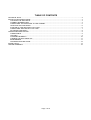
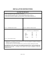
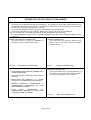
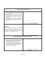
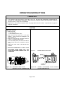
INSTALLATION AND
OPERATING MANUAL
OIL BURNING STOVE
MONT BLANC
Vérified and tested following
CAN/CSA B140.3 et UL 896 standards by:
Intertek Testing Services
Fabricated by:
Stove Builder International Inc
1700 Léon-Harmel
Québec, (Québec)
G1N 4R9
READ THESE INSTRUCTIONS AND SAVE FOR REFERENCE
000629/45089A
TABLE OF CONTENTS
TECHNICAL DATA.............................................................................................................................................. 2
INSTALLATION INSTRUCTIONS ........................................................................................................................ 3
LOCATING THE APPLIANCE ......................................................................................................................... 3
CHIMNEY INFORMATIONS ........................................................................................................................... 4
CONNECTING THE APPLIANCE TO THE CHIMNEY .................................................................................... 5
LEVELLING THE APPLIANCE........................................................................................................................ 6
FIXATION OF THE APPLIANCE TO FLOOR .................................................................................................. 6
CONNECTING APPLIANCE TO OIL TANK .................................................................................................... 7
ADJUSTING THE DRAFT ............................................................................................................................... 8
OPERATION INSTRUCTIONS ............................................................................................................................ 9
COMBUSTIBLE .............................................................................................................................................. 9
LIGHTING ...................................................................................................................................................... 9
CHANGING INTENSITY ............................................................................................................................... 10
TURNING THE APPLIANCE OFF ................................................................................................................. 11
MAINTENANCE............................................................................................................................................ 11
TROUBLESHOOTING GUIDE ...................................................................................................................... 12
SPARE PARTS ................................................................................................................................................. 14
LIMITED WARRANTY ....................................................................................................................................... 16
Page 1 of 15
TECHNICAL DATA
MONT BLANC OIL BURNING STOVE
COMBUSTIBLE :
HEAT INPUT :
Minimum :
Maximum :
FLOWRATE :
Minimum :
maximun :
MINIMUM DRAUGHT REQUIRED :
EFFICIENCY :
with fan :
without fan :
O
OIL N 1
Kw
BTU/h
5,9
20 450
10,9
37 250
cc/min
litres/h
9,9
0,60
17,3
1,04
0,06 INWC
%
74
72
CLEARANCES TO COMBUSTIBLES
Back
Side
Corner
Top
Mm
255
255
255
915
in
10
10
10
36
A MINIMUM CLEARANCE OF 9’’ (230 mm)
FROM SINGLE WALL FLUE PIPE TO
COMBUSTIBLES MUST BE ALLOWED.
O
OIL N 2
Kw
BTU/h
5,2
17 700
9,6
33 150
cc/min
litres/h
8,0
0,48
15,0
0,90
0,06 INWC
%
74,5
72
DIMENSIONS
Height :
Width :
Depth :
Ø outlet flue pipe :
Ø burner :
Glass ( 3 ) :
Weight :
Page 2 of 15
mm
970
550
685
130
255
in
38 ¼
21 ¾
27
5
10
92 x 250
91 kg
3 5/8 x 9 7/8
200 lbs
INSTALLATION INSTRUCTIONS
LOCATING THE APPLIANCE
•
•
•
•
Position the appliance as close as possible to the chimney.
Many configuration are possible, the most frequent are illustrated in figures 1,2 and 3.
Respect clearances indicated on page 1. They have been tested according to approvals.
Always respect clearances of appliance pipe manufacturers. Larger clearances always prevail.
Figure 1 : CORNER INSTALLATION
Figure 2 : PARALLEL INSTALLATION
Table 1 : CLEARANCES TO COMBUSTIBLES
Back
Side
Corners
Top
mm
180
150
150
915
in
7
6
6
36
Flue Pipe
230
9
Figure 3 : WALL INSTALLATION
• IMPORTANT: It is essential to ensure that the room in which the appliance is installed is sufficiently
ventilated to provide an adequate air supply.
• It is possible that if your home is well insulated, that you will have to install an outside fresh air intake.
3
THE BURNING OF ONE LITRE OF FUEL (OIL) REQUIRES APPROXIMATELY 30 M OF AIR AND WILL
3
PRODUCE ABOUT 0.8 KG OF WATER OF WATER VAPOR AND 9 M OF CARBONE DIOXIDE AND
ATMOSPHERIC NITROGEN. A SOURCE OF AIR FROM THE OUTSIDE IS NEEDED TO REPLACE
COMBUSTION AIR.
Page 3 of 15
CHIMNEY INFORMATIONS
• Before the hook up of the appliance, inspect the chimney to ensure that it is in good condition and that the
quality of the flue will allow a sufficient draft. For a good combustion, refer to the technical data of the
appliance to know the minimum draft required.
• Factory built (A) or (L) type chimney is approved for this appliance. The chimney has to be well insulated;
a chimney with a cold internal surface can prevent a good draft and condensation will occur.
• Chimney sections must be of constant diameter. 5" factory built chimney is required An excessively large
diameter will produce too great of a volume, which is more difficult to heat.
• When the appliance is installed on a masonry chimney witch is often oversize, it’s required to use a
stainless steel liner of 5" diameter inside the existing chimney.
• The chimney should be no less than 15' high (including appliance pipes). The chimney has to extend no
less than 3' above the point it exits the roof and 2' higher than any roof, or any other obstacles within a
horizontal distance of 10'.
• CHIMNEY MINMUM HEIGHT :
Height of chimney should inferior than 15’ (4.6
m).
• CLEARANCES WITH ROOF SUMMIT AND
BUILDING NEARBY :
The chimney flue shall extend at least 2’ (0,6 m)
above the highest roof surface or structure within
10’ (3,0 m) horizontally of the chimney.
Figure 5:
Figure 4:
CHIMNEY CLEARANCES
CHIMNEY MINMUM HEIGHT
• CLEARANCE FROM ROOFING INTERSECTION:
The chimney flue shall extend at least 3’ (0,9 m) above the highest point at wich it comes in contact with
the roof. ref.: standard B-139 - 4.2.2.11.
YOUR APPLIANCE SHALL BE CONNECTED TO A CHIMNEY WHICH WILL PROVIDE AN
ADEQUATE DRAFT AT ALL TIMES TO ENSURE SAFE AND PROPER OPERATION OF
THE BURNER
Page 4 of 15
CONNECTING THE APPLIANCE TO THE CHIMNEY
• The gases are vented from the back of the appliance. The female part of the black pipe connector has to
be installed toward the flue connector of the appliance. Secure all connections with the (3) self taping
o
screws, with 120 distance between each of them.
• The connection between appliance pipes and chimney has to be perfectly airtight.
• A maximum horizontal lent of 8' is allowed. Make sure to have a 1/4" slope per foot minimum.
o
• Do not use more than two 90 Elbows while connecting the appliance to the chimney.
• It is strictly forbidden to pass through combustible materials walls, floors and ceilings with appliance pipe
connectors.
DIRECT HORIZONTAL CONNECTION :
You may choose to connect your appliance to
the chimney with an horizontal flue pipe.
CEILING CONNECTION :
In the case where your chimney starts from the
ceiling, use one 90º elbow and the necessary
straight sections.
Figure 6:
Figure 7:
HORIZONTAL CONNECTION.
• THE CHIMNEY MUST NOT BE SHARED WITH
OTHER APPLIANCES
• FIX FLUE PIPES TOGETHER WITH METAL
SCREWS.
CEILING CONNECTION.
VERTICAL CONNECTION :
IT is recommended not to use more than two (2)
90º elbows and the necessary straight sections
to connect your appliance to the chimney.
• MAKE SURE YOU RESPECT A ¼’’ SLOPE
PER FOOT OF HORIZONTAL PIPE LENGTH.
• RESPECT CAREFULLY CLEARANCES TO
COMBUSTIBLES PRESCRIBED BY FLUE
PIPES MANUFACTURERS.
• FLUE
PIPES
CLEARANCES
TO
COMBUSTIBLES DEPEND ON FLUE PIPES
TYPE AND MANUFACTURERS
Figure 8:
Page 5 of 15
VERTICAL CONNECTION.
LEVELLING THE APPLIANCE
• Now that the appliance is in place and properly
hooked up to the chimney, you have to adjust the
level of the burner.
• Put the level on the burner flange parallel to the
door.
(Figure 9A).
Screw or unscrew the
adjustable legs to level the burner with a 7/16" or
10 mm key.
• Put the level on the burner flange parallel to the
sides.
(Figure 9B).
Screw or unscrew the
adjustable legs to level the burner with a 7/16" or
10 mm key
Figure 9A:
LEVELLING THE BURNER
Figure 9B:
LEVELLING THE BURNER
IMPORTANT :
IT IS VERY IMPORTANT THAT THE BURNER
ALWAYS
STAND
ON
LEVEL
TO
ALLOW
A
PROPER OIL VAPOR DISTRIBUTION THROUGH
THE RINGS, AND A BETTER OIL INLET.
FIXATION OF THE APPLIANCE TO FLOOR
• The appliance must be fixed in its location using
the two fixation brackets. Install the brackets on
the two back adjustable legs. (figure 11)
• If the flooring is made of combustible material it
would be preferable to install the appliance on
an non combustible surface covering at least to
the dimensions of the appliance.
Figure 10:
Page 6 of 15
INSTALLATION OF FIXATION
BRACKETS
CONNECTING APPLIANCE TO OIL TANK
• Make sure that the tank outlet is 12" (305 mm) higher than the inlet of the carburetor. (Gravity fed)
• Use only copper piping to connect tank to appliance.
• Make sure that there is a small slope on the connection from the tank toward the appliance.
• A 3" (75 mm) down slope is needed on the tank itself, from the outlet towards the other end of the tank.
• When the tank is installed outdoors, it is preferable to use oil #1, to avoid viscosity problems.
NOTE :
THE BAROMETRIC TANK SHALL BE LOCATED SO THAT THE TANK WILL NOT BE
EXPOSED TO THE DIRECT RAYS OF THE SUN OR ADJACENT TO ANY SOURCE OF
INTENSE HEAT.
Figure 11 :
APPLIANCE AND OIL TANK CONNECTION
Page 7 of 15
ADJUSTING THE DRAFT
• Your appliance operated with natural draft, created by the ascension of combustion gases in the chimney.
This movement creates a suction effect in the appliance and forces ambient air to go in the burner by the
holes in its surround. These orifices let air in for combustion.
• For the appliance to function properly, it is essential to check the quality of the draft using a draft gauge.
The draft is usually measured in inches of water column.
• Check the minimum draft required of the appliance on page 1. The draft mentioned has to be reached
rapidly at a minimum settling (position #1).
• Depending on the model, the draft can be taken by the orifice on the cooking surface. The measure can
also be taken by the orifice on the draft regulator usually plugged by a rubber cap. The orifice on the
cooking surface is still the best area.
IMPORTANT : ALWAYS MEASURE THE DRAFT WITH ALL VENTILATION EQUIPMENT INSTALLED IN
THE HOUSE (RANGE HOOD, BATHROOM FAN, AIR EXCHANGER, DRYER, ETC IN OPERATION.)
ref. : standard CAN/CSA B-139 art. 4.1.5.
DRAFT REGULATOR
• An excessive draft is as bad as a low one.
• The regulator controls the draft when it is
excessive (in high winds for example).
• If the draft exceeds 0.08 in of water column, you
will have to adjust the regulator.
To adjust the draft you have to screw or unscrew the
counterweight on the regulator. Opened regulator:
lowers the draft. Closed regulator: increases the draft
Figure 12:
DRAFT REGULATOR
THE ONLY RIGHT WAY OF MEASURING THE DRAFT IS TO USE A DRAFT GAUGE THAT GIVES A
READING IN INCHES OF WATER COLUMN. ANY OTHER METHOD (CANDLE, MATCHES, ETC.) ARE
UNRELIABLE.
INSTALLATION OF YOUR APPLIANCE SHALL BE IN ACCORDANCE WITH CAN/CSA B-139
INSTALLATION CODE FOR OIL-BURNING EQUIPMENT IN CANADA AND STANDARD NFPA 31
NATIONAL FIRE PROTECTION ASSOCIATION STANDARD FOR OIL-BURNING EQUIPMENT IN THE
U.S..
THE INSTALLATION SHALL BE MADE BY A QUALIFIED PERSON MEMBER OF THE CORPORATION IN
FORCE IN YOUR AREA.
Page 8 of 15
OPERATION INSTRUCTIONS
COMBUSTIBLE
• Your appliance has been design to work with oil #1 or #2. DO NOT USE GASOLINE, CRANKCASE OIL
OR ANY OIL CONTAINING GASOLINE. Drolet Stoves & Fireplaces declines all responsibility regarding
damage cause by using other combustibles.
• Make sure to use oil without impurities which may plug filters and valve’s orifice. Impurities will only give an
improper combustion.
LIGHTING
BEFORE LIGHTING
• Make sure that :
The tank is full;
The isolating valve is open;
• See that the (3) rings are in the right
position. Each of them are stamped A, B
and C (figure 13).
• Make sure that the flow regulating handle is
in the « 0 » position (figure 14B).
• If it’s not already done, arm down the valve’s
lever located behind the appliance (figure
14A).
• Wait for the valve to fill up and let the level
stabilize.
• BEFORE ATTEMPTING TO LIGHT YOUR
APPLIANCE, MAKE SURE THAT THE
FLOW REGULATING HANDLE IS IN THE
0 POSITION.
Figure 14B: CONSTANT LEVEL FLOW
CONTROL VALVE (CARBURATOR)
Figure 13:
BURNER RINGS POSITION
Figure 14A:
ARMING / DESARMING FLOW CONTROL
VALVE (CARBURATOR).
Page 9 of 15
LIGHTING (CONT’D)
• Place the flow regulating handle on the "1" position, as soon as the oil has started flowing into the
burner, return to "0" position.
• Open the door and pore into the burner 2 to 3 once (75 ml) of lighting gel or wood alcohol.
NOTE : USING LIGHTING GEL IS BETTER FOR A SAFE IGNITION.
• With a long wood match or a BBQ lighter ignite carefully and close the door.
• After a couple of minutes (before alcohol goes out) the burner and the chimney are will have
warmed, place the flow regulator handle on "1" position.
Note : Do not leave matches or other materials in the burner in order to keep it
clean. It allows a better combustion.
IF YOU MISS THE APPLIANCE’S LIGHTING, ALWAYS WAIT FOR THE
BURNER TO COOL DOWN TO ROOM TEMPERATURE BEFORE USING
BURNING ALCOHOL AGAIN.
IF, FURTHER TO SOME MISOPERATION, THE BURNER FINDS ITSELF
WITH AN EXCESS QUANTITY OF OIL, ALL OF THE OIL MUST FIRST BE
REMOVED BEFORE LIGHTING THE APPLIANCE AGAIN.
CHANGING INTENSITY
• Always wait 10 minutes minimum before increasing the flow (between each position). This allows flame to
stabilize and prevents soot build-up.
• No waiting is needed to decrease the flow.
Page 10 of 15
TURNING THE APPLIANCE OFF
• Set the flow regulating handle to position 0.
• If you plan to keep the appliance off for a long while, it is recommended to disarm the valve’s lever and
close the tap on the pipe between the appliance and your oil tank.
ALWAYS KEEP THE VALVE SHUT OFF WHEN THE BURNER IS NOT OPERATING
MAINTENANCE
ONCE A WEEK :
• Clean the oil inlet tube of the burner with the
cleaning tee :
Push in the rod of the cleaning tee while
turning it
Move back and forth operation 2 or 3 times;
Pull it back into place to finish the operation.
Figure 15 : CLEANING TEE
WHEN YOUR APPLIANCE IS RUNNING, ALWAYS KEEP THE CLEANING TEE LEVER PULLED BACK
INTO PLACE.
ONCE A MONTH OR TWO :
• Clean with a metallic brush;
• The burner’s shell;
• The burner’s rings;
• The burner’s catalyst (in blue flame model).
AT THE BEGINNING OF EACH HEATING SEASON :
• Clean the valve and tank filters;
• Inspect the smoke box through the opening of the rear flue outlet.;
• Clean the chimney and flue pipe.
MAKE SURE THAT ALL HAND VALVES ARE CLOSED BEFORE CLEANING PROCEDURES.
WHEN NEEDED :
• Clean the door glasses.
• Always clean the glasses when the appliance is cold. Use commercial product for this purpose, or a water
and vinegar solution.
Page 11 of 15
TROUBLESHOOTING GUIDE
PROBLEMS
CAUSES
SOLUTION
ON POSITION 6 (MAXIMUM)
THE FLAME IS LONGER AND
PRODUCES SMOKE, THERE
IS SOOT BUILD-UP ON THE
GLASS
Position 6 was reached too
quickly.
1. Set flow regulating handle to
position 1.
2. wait for combustion to
stabilize.
3. Progressively increase flow
to desired position.
NOTE :
SEE
LIGHTING
PROCEDURES.
Maximum flow is too high
1. Set flow to a lower position
2. Call a qualified technician to
adjust the valve.
Cleaning tee and/or burner are
dirty
1. Activate
cleaning
tee
according to procedures
2. Schedule at the next shut off
to clean the burner.
plunger`s
blocked
1. Progressively increase flow
to position 6.
2. Push in many consecutive
times on the thermostatic
regulator bottom to remove
dirt form the orifice.
ON POSITION 1 (MINIMUM)
THE FLAME PRODUCES
SMOKE AND SOOT BUILD-UP
ON THE GLASS
orifice
is
partially
NOTE : If the problem persist,
you may have to remove and
clean out the valve with alcohol.
Call your certified technician.
ON POSITION 1 (MINIMUM)
THE FLAME PRODUCES
SMOKE AND SOOT BUILD-UP
ON THE GLASS
Flow is to low
Page 12 of 15
1. Slightly increase the flow
regulating handle.
2. Call a certified technician.
TROUBLESHOOTING GUIDE (CONT’D)
PROBLEMS
THE FLAME PRODUCES
SMOKE, IN ANY POSITION
FLAME GOES OUT
THE APPLIANCE MAKES
NOISE, GOES OUT AND LIGHT
UP AGAIN
CAUSES
Door gasket
properly
is
not
SOLUTION
sealed
1. Tighten door by turning
counter-clockwise the door
handle.
2. Check if gasket needs to be
changed.
The burner orifices are plugged
up
1. Clean the burner
metallic brush.
with
a
DRAFT is too low
1. Make it checked
technician
by
a
Oil level in the tank is too low
1. Fill up the tank.
Air pocket is stocked in the oil
line
1. Call a technician to drain the
line
2. Make sure that the oil line has
an adequate slope towards
the tank.
Oil #2 is used in exterior tank
1. Use only oil #1 when tank is
installed outside.
Partial or total obstruction by
impurities in oil line or filters
1. Check filters on tank and
valve.
2. Ask a technician to verify the
cleanness of the tank and
line.
The appliance has been lit with
an oil excess in the burner
1. Position the flow regulating
handle to 0.
2. Let the appliance cool down.
3. Clean
the
burner
if
necessary.
Note : Never light the appliance
when the burner is full of oil.
Sponge the oil out before
lighting.
Page 13 of 15
SPARE PARTS
After years of use, if you need to replace some parts, please contact your SUPPLIER or one of our Drolet
approved DEALERS.
• Give him product data as displayed in your warranty voucher or on your appliance’s name plate at the rear.
Keep the warranty voucher even after its EXPIRY date.
• Our dealers are in possession of all spare parts nomenclatures and technical data about our products, and
will provide you with the spare parts you need and any maintenance intervention within the scope of their
professional competence.
NO
DESCRIPTION
1
Handle
2
Door
3
Sealing joint for window panes
4
Pyrex slivers
5
Sealing joint for door
6
Draught regulator
7
Fan
8
Fan control
9
Pan
10
Valve
11
Valve support
12
Valve heat shield
13
Cleaning tee
14
Pot liner
15
Pot
16
Burner ring
17
Copper tube
18
Catalyst
Page 14 of 15
SPARE PARTS (CONT’D)
Figure 16:
MONT BLANC EXPLODED VIEW, SPARE PARTS LIST
Page 15 of 15
1700, rue Léon-Harmel, Québec (Québec) G1N 4R9
tel. : (418) 527-3060 fax : (418) 527-4311
e-mail : [email protected] web site : drolet .ca
LIMITED WARRANTY
The Drolet Stoves & Fireplaces warranty extends only to the original consumer purchaser and is not transferable. This
warranty covers brand new products only, which have not been altered, modified nor repaired since shipment from factory. Proof
of purchase (dated bill of sale), model name and serial number must be supplied when making any warranty claim to your
Drolet Stoves & Fireplaces dealer
This warranty applies to normal residential use only. Damages caused by misuse, abuse, improper installation, lack of
maintenance, over firing, negligence or accident during transportation are not covered by this warranty.
This warranty does not cover any scratch, corrosion or discoloration caused by over firing, abrasives or chemical cleaners. Any
defect or damage caused by the use of unauthorized parts or others than original parts void this warranty.
An authorized qualified technician must perform the installation in accordance with the Instructions supplied with this product
and all local and national building codes. Any service call related to an improper installation is not covered by this warranty.
Returned products are to be shipped prepaid to Drolet Stoves & Fireplaces for investigation. If a product is found to be
defective, Drolet Stoves & Fireplaces will repair or replace such defect and reasonable transportation fees will be refund.
Repair work covered by the warranty, executed at the purchaser domicile by an authorized qualified technician requires the prior
approval of Drolet Stoves & Fireplaces. Labour cost and repair work to the account of Drolet Stoves & Fireplaces are based
on predetermined rate schedule and must not exceed the wholesale price of the replacement part.
Drolet Stoves & Fireplaces at its discretion may decide to repair or replace any part or unit after inspection and investigation of
the defect. Drolet Stoves & Fireplaces may, at its discretion, fully discharge all obligations with respect to this warranty by
refunding the wholesale price of any warranted but defective parts
Drolet Stoves & Fireplaces shall in no event be responsible for any special, indirect, consequential damages of any nature,
which are in excess of the original purchase price of the product.
WARRANTY APPLICATION
DESCRIPTIION
PARTS
Combustion chamber (Weldings Only)
lifetime
Stainless Baffle
5 ans
Carbon Steel Baffle
2 ans
Coil Handle
5 ans
Cast Iron
5 ans
Ceramic glass (thermal breakage only)
1 an
Burner
1 an
Gaskets, Blower, Switch (thermodisc), Rheostat, Paint, Burner Rings,
1 an
Catalyst Ring
Valve (Carburettor)***
1 an
Gold Plating (Tarnishing Only)
lifetime
***Note : No modification or adjustment to the valve is permitted. Any changes to the valve void the warranty.
LABOUR
5 ans
1 an
1 an
n/a
1 an
n/a
1 an
n/a
1 an
1 an
Shall your unit or a components be defective, contact immediately your Drolet Stoves & Fireplaces dealer. Prior to your call
make sure you have the following information necessary to your warranty claim treatment:
•
•
You name, address and telephone number;
Bill of sale, dealer’s name;
•
Serial number and model name as indicated on the
nameplate fixed to the back of your unit;
•
Nature of the defect and any relevant information.
Before shipping your unit or defective component to our plant, you must obtain from your Drolet Stoves & Fireplaces dealer an
Authorization Number. Any merchandise shipped to our plant without authorization will be refused automatically and returned to
sender.
Page 16 of 15