1
arm carries the shield for the playback-head and the tape-lift mechanism for the
rewind function.
The brakes are mechanical in nature but are electrically operated. This is achieved by
the action of the brake solenoid which pulls the brakes off during all operating
functions. When the stop button is pressed however, or when the current fails for any
reason, the solenoid is de-energized, and the brakes automatically come on, with the
higher braking force always on the trailing spindle.
All functions are controlled by the push buttons. Arcing damage and noise is
prevented by the use of diodes and RC networks. A sensing lever on the RH tape
guide (3 in fig. 1 and 8) operates a switch (SE on schematic) which, in series with the
stop button, provides a current path to a solenoid incorporated in the push button unit.
This has the effect of clearing any selected function either by depressing the stop
button or operation of the end of tape switch. On recorders up to serial No. 36 500,
the function of the end of tape switch is delayed by about two seconds to avoid
tripping during the start mode. On machines with higher serial numbers (recognizable
by the end-of-tape switch being made of gold-plated wire with NC contact
configuration) this time delay (relais) has been utilized to supply increased operating
voltage to the wind motors, thus providing the required starting torque. (Inset
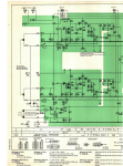
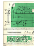
schematic B and diagram 7.736.001-002:6 refer.)
The tape guide pins to the left and right hand side of the loading slot assist in
achieving uniform tape tension due to the change in friction with varying wrap-around
from large to small spooling diameters.
A three digit tape counter is driven from the take-up turntable by a rubber belt. The
translucent resetting knob of the counter is lit by a small pilot bulb which acts as a
mains indicator.
A remote control facility is provided
Removal of the shorting link from the socket on the rear panel and the insertion of the
correct accessory plug, lead and switch, enables the recorder to be started or stopped
in either the record or playback function as selected. Operation of the remote control
switch has the effect of de-energizing both the capstan and brake solenoids.
ATTENTION If no remote control is used, the dummy plug must be inserted into the
socket, otherwise the recorder will not start.
2.1 Mechanical checks and adjustments
It is advisable to use a full and an empty 10 1/2 inch spool when carrying out
adjustments. For the majority of tape transport checks, it is essential to keep the
plastic top cover in position. For other mechanical adjustments the top and head
covers should be removed. To remove the plastic top plate, pull off the grey control
knobs, the transparent selector discs and the plastic cover over the pinch-roller arm.
Further undo the mounting screws (1 in fig. 2) of both turntables, of the head cover
and the mounting lugs (2 in fig. 1) of the pinch-roller cover. When reassembling, take