1
Industrial
Hydraulics
Electric Drives
and Controls
Linear Motion and
Assembly Technologies
Pneumatics
Service
Automation
Mobile
Hydraulics
Rexroth IndraControl VCP 20
Rexroth SYNAX 200
Version 12
Project Planning Manual
R911307347
Edition 01
About this Documentation
Title
Rexroth SYNAX 200
Rexroth SYNAX 200
Version 12
Type of Documentation
Document Typecode
Internal File Reference
Project Planning Manual
DOK-SYNAX*-SY*-12VRS**-PR01-EN-P
• Box 40-12V-EN
• Sy112E_O.doc
• Document Number 120-2200-B352-01/EN
Purpose of Documentation
This documentation assists
• in the selection of units and hardware components and
• in the basic control cabinet construction
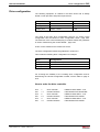
Record of Revisions
Copyright
Description
Release
Date
Notes
DOK-SYNAX*-SY*-12VRS**-PR01-EN-P
09.04
Version 12VRS
2004 Bosch Rexroth AG
Copying this document, giving it to others and the use or communication
of the contents thereof without express authority, are forbidden. Offenders
are liable for the payment of damages. All rights are reserved in the event
of the grant of a patent or the registration of a utility model or design
(DIN 34-1).
Validity
Published by
The specified data is for product description purposes only and may not
be deemed to be guaranteed unless expressly confirmed in the contract.
All rights are reserved with respect to the content of this documentation
and the availability of the product.
Bosch Rexroth AG
Bgm.-Dr.-Nebel-Str. 2 • D-97816 Lohr a. Main
Telephone +49 (0)93 52/40-0 • Tx 68 94 21 • Fax +49 (0)93 52/40-48 85
http://www.boschrexroth.com/
Dept. BRC/ESP (STS/TD)
Note
This document has been printed on chlorine-free bleached paper..
DOK-SYNAX*-SY*-12VRS**-PR01-EN-P
Rexroth SYNAX 200
About this Documentation
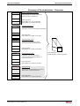
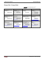
Summary of Documentation - Overview
Functional Description; Interfaces:
Help familiarize the user with SYNAX 200
and the functions of SYNAX 200
FK
Order designation:
DOK-SYNAX*-SY*-12V*1/2-FK01-EN-P
DOK-SYNAX*-SY*-12V*2/2-FK01-EN-P
Parameter Description:
Description of the SYNAX 200 system parameters
PA
Order designation:
DOK-SYNAX*-SY*-12VRS**-PA01-EN-P
Trouble Shooting Guide:
Explanation of the diagnostics states
How to proceed when eliminating faults
WA
Order designation:
DOK-SYNAX*-SY*-12VRS**-WA01-EN-P
Firmware Version Notes:
Description of the new and changed
functions between SYNAX 200 version 12
and previous version 11
FV
Order designation:
DOK-SYNAX*-SY*-12VRS**-FV01-EN-P
Project Planning:
Selection of units and hardware components
Basic control in cabinet construction
PR
Order designation:
DOK-SYNAX*-SY*-12VRS**-PR01-EN-P
DOK-SYNAX*-SY*-12VRS**-PR01-EN-P
Order designation:
DOK-SYNAX*-SY*-12VRS**-4001-EN-P
About this Documentation
Rexroth SYNAX 200
DOK-SYNAX*-SY*-12VRS**-PR01-EN-P
Rexroth SYNAX 200
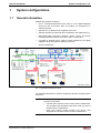
Contents I
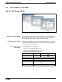
Contents
1
System configurations
1-1
1.1
General information ...................................................................................................................... 1-1
1.2
System components ..................................................................................................................... 1-2
Motion control components (MotionControl and PLC) ............................................................ 1-2
I/O components ....................................................................................................................... 1-4
HMI components...................................................................................................................... 1-6
Drives, motors.......................................................................................................................... 1-8
1.3
2
System structures ....................................................................................................................... 1-10
Important directions for use
2.1
2-1
Appropriate use ............................................................................................................................ 2-1
Introduction .............................................................................................................................. 2-1
Areas of use and application ................................................................................................... 2-2
2.2
3
Inappropriate use.......................................................................................................................... 2-2
Safety Instructions for Electric Drives and Controls
3-1
3.1
Introduction ................................................................................................................................... 3-1
3.2
Explanations ................................................................................................................................. 3-1
3.3
Hazards by Improper Use............................................................................................................. 3-2
3.4
General Information ...................................................................................................................... 3-3
3.5
Protection Against Contact with Electrical Parts........................................................................... 3-5
3.6
Protection Against Electric Shock by Protective Low Voltage (PELV) ......................................... 3-6
3.7
Protection Against Dangerous Movements .................................................................................. 3-7
3.8
Protection Against Magnetic and Electromagnetic Fields During Operation and
Mounting ....................................................................................................................................... 3-9
3.9
Protection Against Contact with Hot Parts.................................................................................. 3-10
3.10 Protection During Handling and Mounting.................................................................................. 3-10
3.11 Battery Safety ............................................................................................................................. 3-11
3.12 Protection Against Pressurized Systems.................................................................................... 3-11
4
Motion control configuration
4.1
4-1
Procedure ..................................................................................................................................... 4-1
Selecting the motion control configuration without PLC (MotionControl subsystem).............. 4-1
Selecting the motion control configuration with PLC ............................................................... 4-2
Selecting the firmware ............................................................................................................. 4-3
4.2
MotionControl PPC-R ................................................................................................................... 4-4
4.3
Brief description PPC-P ................................................................................................................ 4-5
4.4
Brief description option cards ....................................................................................................... 4-6
Option cards for the MotionControl.......................................................................................... 4-6
DOK-SYNAX*-SY*-12VRS**-PR01-EN-P
II Contents
Rexroth SYNAX 200
Option Cards for the PLC ........................................................................................................ 4-8
4.5
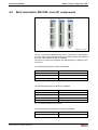
Brief description RECO02: local I/O components ........................................................................ 4-9
4.6
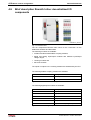
Brief description Rexroth Inline: decentralized I/O components................................................. 4-10
4.7
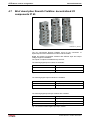
Brief description Rexroth Fieldline: decentralized I/O components IP 65 .................................. 4-12
4.8
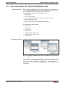
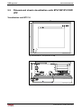
Brief description PC based visualization units............................................................................ 4-13
4.9
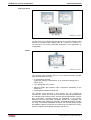
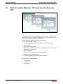
Brief description Windows CE based visualization units VEP.................................................... 4-15
4.10 Brief description miniature control terminal VCP ........................................................................ 4-16
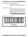
4.11 Installation instructions RECO control ........................................................................................ 4-17
Installing the module carriers................................................................................................. 4-17
Arrangement of the module carrier........................................................................................ 4-17
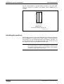
Installing the modules ............................................................................................................ 4-18
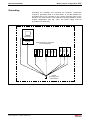
Grounding .............................................................................................................................. 4-19
4.12 Slot addressing of the module carriers ....................................................................................... 4-20
4.13 Combination options module carrier - PPC - I/O modules ......................................................... 4-21
Motion control configuration .................................................................................................. 4-21
4.14 Installation instructions PPC-P control ....................................................................................... 4-22
4.15 Combination possibilities visualization units BTV - PPC-P ........................................................ 4-23
4.16 Specifications PPC-R2x.............................................................................................................. 4-24
General specifications PPC-R2x ........................................................................................... 4-24
Power supply PPC-R2x ......................................................................................................... 4-24
I/O Bus supply by control....................................................................................................... 4-24
Digital inputs and outputs of the PPC-R2x ............................................................................ 4-25
EMC of the PPC-R2x............................................................................................................. 4-25
DERATING I/O bus supply .................................................................................................... 4-25
Interfaces of the PPC-R2x..................................................................................................... 4-25
Connecting the power supply of the PPC-R2x ...................................................................... 4-26
Connector pin assignments of the PPC-R2x......................................................................... 4-26
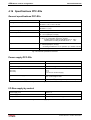
4.17 Specifications PPC-P11.............................................................................................................. 4-28
General specifications PPC-P ............................................................................................... 4-28
Power supply PPC-P ............................................................................................................. 4-28
Digital inputs and outputs of the PPC-P ................................................................................ 4-28
Interfaces of the PPC-P......................................................................................................... 4-28
Connector pin assignment of the PPC-P............................................................................... 4-29
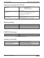
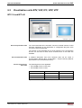
4.18 Procedure at HMI components ................................................................................................... 4-30
General information ............................................................................................................... 4-30
Software for compact devices (VCP)..................................................................................... 4-30
Software for Windows CE based devices and PC based devices ........................................ 4-31
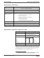
4.19 Specifications BTV 16, BTV 40 .................................................................................................. 4-32
Specifications of the front ...................................................................................................... 4-32
Specifications of the PC box.................................................................................................. 4-33
Specifications of the power supply 115V / 230V ................................................................... 4-34
Specifications of the power supply 24V................................................................................. 4-34
Ambient conditions BTV 16, BTV 40 ..................................................................................... 4-35
Wear parts BTV 16, BTV 40 .................................................................................................. 4-35
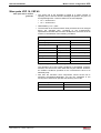
4.20 Specifications VSP 16, VSP 40 .................................................................................................. 4-36
Specifications of the front ...................................................................................................... 4-36
DOK-SYNAX*-SY*-12VRS**-PR01-EN-P
Rexroth SYNAX 200
Contents III
Specifications of the PC box.................................................................................................. 4-37
Specifications of the power supply 115V / 230V ................................................................... 4-37
Specifications of the power supply 24V................................................................................. 4-38
Ambient conditions VSP 16, VSP 40..................................................................................... 4-38
Wear parts VSP 16, VSP 40.................................................................................................. 4-39
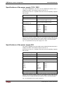
4.21 Specifications IPC/VSB with VDP 16, VDP 40 ........................................................................... 4-40
Specifications of the front ...................................................................................................... 4-40
Specifications of the PC box.................................................................................................. 4-41
Specifications of the power supply 115V / 230V ................................................................... 4-42
Specifications of the power supply 24V................................................................................. 4-42
Ambient conditions VDP 16, VDP 40, IPC 40/VSB40 ........................................................... 4-43
Wear parts VDP 16, VDP 40, IPC 40/VSB 40....................................................................... 4-43
4.22 Specifications VPP21 ................................................................................................................. 4-45
Specifications of the front ...................................................................................................... 4-45
Specifications of the overall device ....................................................................................... 4-45
Specification of the PC .......................................................................................................... 4-46
Ambient conditions VPP 21 ................................................................................................... 4-46
Wear parts VPP 21 ................................................................................................................ 4-47
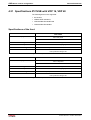
4.23 Specifications VEP 30, VEP 40, VEP 50.................................................................................... 4-48
Specifications of the front ...................................................................................................... 4-48
Specifications of the processor.............................................................................................. 4-48
Specifications of the interfaces.............................................................................................. 4-48
Specifications of the power supply 24V................................................................................. 4-49
General specification VEP 30, VEP 40, VEP 50 ................................................................... 4-49
Ambient conditions VEP 30, VEP 40, VEP 50 ...................................................................... 4-49
Wear parts VEP 30, VEP 40, VEP 50 ................................................................................... 4-49
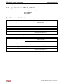
4.24 Specification miniature control terminal VCP 01 ........................................................................ 4-50
General specification VCP 01................................................................................................ 4-50
Connector pin assignments of the VCP 01 (serial interface) ................................................ 4-51
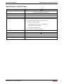
4.25 Specification miniature control terminal VCP 02 ........................................................................ 4-52
General specifications VCP 02.............................................................................................. 4-52
Connector pin assignment VCP 02 (serial interface) ............................................................ 4-52
Connector pin assignment VCP 02 (Profibus DP interface).................................................. 4-54
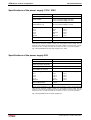
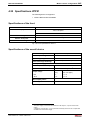
4.26 Specification miniature control terminal VCP 05 ........................................................................ 4-55
General specification VCP 05................................................................................................ 4-55
Connector pin assignments of the VCP 05 (serial interface) ................................................ 4-55
Connector pin assignments of the VCP 05 (Profibus DP interface)...................................... 4-57
Connector pin assignment VCP 05 (DeviceNet interface) .................................................... 4-58
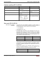
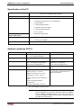
4.27 Specification miniature control terminal VCP 08 ........................................................................ 4-60
General specification VCP 08................................................................................................ 4-60
Connector pin assignments of the VCP 08 (serial interface) ................................................ 4-60
Connector pin assignments of the VCP 08 (Profibus DP interface)...................................... 4-62
Connector pin assignment VCP 08 (DeviceNet interface) .................................................... 4-63
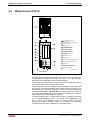
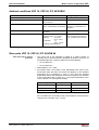
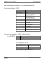
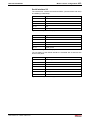
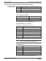
4.28 Specification miniature control terminal VCP 20 ........................................................................ 4-64
General specification VCP 20................................................................................................ 4-64
Connector pin assignments of the VCP 20 (serial interface) ................................................ 4-64
DOK-SYNAX*-SY*-12VRS**-PR01-EN-P
IV Contents
Rexroth SYNAX 200
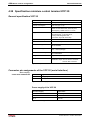
Connector pin assignments of the VCP 20 (Profibus DP interface)...................................... 4-66
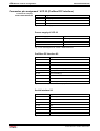
Connector pin assignment VCP 20 (DeviceNet interface) .................................................... 4-67
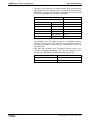
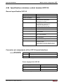
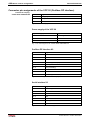
4.29 Specification miniature control terminal VCP 25 ........................................................................ 4-68
General specification VCP 25................................................................................................ 4-68
Connector pin assignments of the VCP 25 (serial interface) ................................................ 4-68
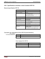
Connector pin assignments of the VCP 25 (Profibus DP interface)...................................... 4-70
Connector pin assignment VCP 25 (DeviceNet interface) .................................................... 4-71
5
Drive configurations
5.1
5-1
Procedure ..................................................................................................................................... 5-1
a) Definition of precision requirements.................................................................................... 5-1
b) Selecting the suitable motor/controller combinations.......................................................... 5-2
c) Determining the drive configuration labeling ....................................................................... 5-2
5.2
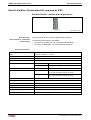
Rotary axes................................................................................................................................... 5-4
Drive with step-down gear and indirect position detection ...................................................... 5-4
Drive with step-down gears and direct incremental position detection ................................... 5-7
Drive with step-down gear and direct absolute position detection ........................................ 5-10
Drive with indirect position detection ..................................................................................... 5-13
Drive with direct incremental position detection .................................................................... 5-14
Drive with direct absolute position detection ......................................................................... 5-18
5.3
Linear axes ................................................................................................................................. 5-22
Drive with indirect position detection ..................................................................................... 5-22
Drive with direct incremental position detection .................................................................... 5-25
Drive with direct absolute position detection ......................................................................... 5-28
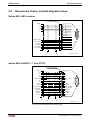
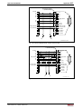
Drive with linear motor and incremental position detection................................................... 5-31
Drive with linear motor and absolute position detection ........................................................ 5-34
5.4
Determining the control-related I/O option.................................................................................. 5-37
Determining parallel I/Os (IndraDrive with option MD1) ........................................................ 5-37
Determining parallel I/Os (Diax) ............................................................................................ 5-37
Combination options of the external I/O (drive internal) ........................................................ 5-38
Determining the master axis.................................................................................................. 5-39
Determining analog inputs..................................................................................................... 5-41
Master axis position output.................................................................................................... 5-41
Determining the safety options of IndraDrive ........................................................................ 5-42
Encoder branching DGA 01.2 for encoders with sinusoidal voltage signals 1Vss................ 5-43
5.5
Drive configurations IndraDrive .................................................................................................. 5-48
5.6
Drive configurations DKR/Diax 04 .............................................................................................. 5-48
General information ............................................................................................................... 5-48
Drive configurations DKR based on the basic configuration BE12 ....................................... 5-48
Drive configurations DKR based on basic configuration BE32 ............................................. 5-50
Drive configuration DKR based on basic configuration BE37 ............................................... 5-52
Drive configuration DKR based on basic configuration BE45 ............................................... 5-54
Drive configuration Diax 04 based on basic configuration HS12 .......................................... 5-56
Drive configuration Diax 04 based on basic configuration HS32 .......................................... 5-58
Drive configuration Diax 04 based on basic configuration HS37 .......................................... 5-60
Drive configuration Diax 04 based on basic configuration HS45 .......................................... 5-62
DOK-SYNAX*-SY*-12VRS**-PR01-EN-P
Rexroth SYNAX 200
5.7
Contents V
Example ...................................................................................................................................... 5-64
Motion control configuration .................................................................................................. 5-64
Drive configuration................................................................................................................. 5-65
6
Order data/reference lists
6.1
6-1
Motion control components........................................................................................................... 6-1
PPC-R: MotionControl ............................................................................................................. 6-1
PPC-P: MotionControl ............................................................................................................. 6-3
Option cards based on the MotionControl............................................................................... 6-4
Option cards based on the PLC .............................................................................................. 6-9
RMB02: Module carrier for PPC-R ........................................................................................ 6-11
RECO02: Local I/O components ........................................................................................... 6-12
Rexroth Inline: Decentralized I/O components...................................................................... 6-28
Rexroth Fieldline: Decentralized I/O components IP65......................................................... 6-44
6.2
Visualization units BTV, VSP, IPC, VDP, VPP ........................................................................... 6-49
BTV 16 and BTV 40............................................................................................................... 6-49
VSP 16 and VSP 40 .............................................................................................................. 6-52
IPC 40/VSB 40 with VDP 16 or VDP 40................................................................................ 6-55
VPP 21................................................................................................................................... 6-59
6.3
Visualization units VEP............................................................................................................... 6-60
VEP 30, VEP 40 and VEP 50 ................................................................................................ 6-60
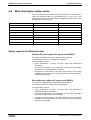
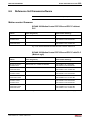
6.4
Miniature control terminals.......................................................................................................... 6-64
Miniature control terminal VCP 01......................................................................................... 6-64
Miniature control terminal VCP 02......................................................................................... 6-66
Miniature control terminal VCP 05......................................................................................... 6-68
Miniature control terminal VCP 08......................................................................................... 6-70
Miniature control terminal VCP 20......................................................................................... 6-72
Miniature control terminal VCP 25......................................................................................... 6-74
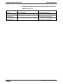
6.5
Drive components....................................................................................................................... 6-76
Drive package IndraDrive ...................................................................................................... 6-76
Drive package DKR ............................................................................................................... 6-84
Drive package Diax 04 .......................................................................................................... 6-88
Drive package EcoDrive ........................................................................................................ 6-95
6.6
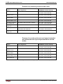
Reference list firmware/software ................................................................................................ 6-99
Motion control firmware ......................................................................................................... 6-99
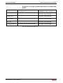
Drive firmware...................................................................................................................... 6-101
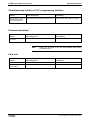
Commissioning interface / PLC programming interface...................................................... 6-104
Firmware download ............................................................................................................. 6-104
Cam tool .............................................................................................................................. 6-104
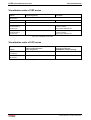
HMI software........................................................................................................................ 6-105
Visualization units of VEP series ......................................................................................... 6-106
Visualization units of VCP series......................................................................................... 6-106
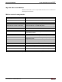
System documentation ....................................................................................................................... 6-107
Motion control components ................................................................................................. 6-107
Drive components................................................................................................................ 6-108
Visualization units PC based ............................................................................................... 6-108
DOK-SYNAX*-SY*-12VRS**-PR01-EN-P
VI Contents
Rexroth SYNAX 200
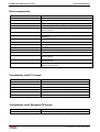
Visualization units Windows CE based ............................................................................... 6-108
Miniature control terminals VCP .......................................................................................... 6-109
7
Fibre-optics cable connections
7.1
7-1
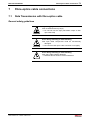
Data Transmission with fibre-optics cable .................................................................................... 7-1
General safety guidelines ........................................................................................................ 7-1
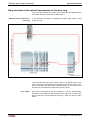
Ring structure of the optical transmission in the drive ring...................................................... 7-2
Ring structure of the optical transmission in the PPC link....................................................... 7-3
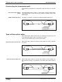
Constructing the transmission path ......................................................................................... 7-4
Types of fibre-optics cables..................................................................................................... 7-4
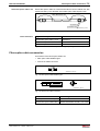
Fibre-optics cable accessories ................................................................................................ 7-5
7.2
Project planning notes .................................................................................................................. 7-6
General notes .......................................................................................................................... 7-6
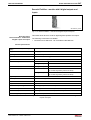
Maximum lengths of the fibre-optics cables ............................................................................ 7-6
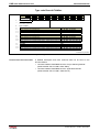
Technical data of available fibre-optics cables........................................................................ 7-6
Handling................................................................................................................................... 7-7
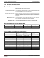
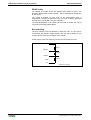
Connections of the fibre-optics cables at motion control or drive............................................ 7-8
7.3
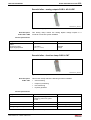
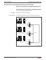
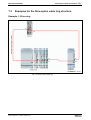
Examples for the fibre-optics cable ring structure ...................................................................... 7-11
Example 1: Drive ring ............................................................................................................ 7-11
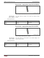
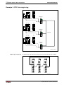
Example 2: PPC link single ring ............................................................................................ 7-12
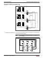
Example 3: PPC link double ring ........................................................................................... 7-13
8
Set-Up interfaces (SynTop, DOLFI)
8-1
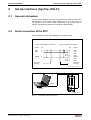
8.1
General information ...................................................................................................................... 8-1
8.2
Serial connection of the PPC........................................................................................................ 8-1
8.3
RS485 link .................................................................................................................................... 8-2
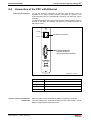
8.4
Connection of the PPC with Ethernet ........................................................................................... 8-7
8.5
Firmware update (DOLFI)............................................................................................................. 8-8
DOLFI version 01VRS ............................................................................................................. 8-8
DOLFI version 02VRS ............................................................................................................. 8-8
9
Appendix
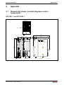
9.1
9-1
Dimensional sheets, terminal diagrams control components ....................................................... 9-1
PPC-R21.1 and PPC-R22.1 .................................................................................................... 9-1
Option cards based on the MotionControl (for the PPC)......................................................... 9-2
Option cards based on the PLC (for the PPC) ........................................................................ 9-5
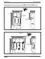
Mounting dimensions module carrier RMB02.2-02 and RMB02.2-04..................................... 9-6
9.2
Dimensional sheets, terminal diagrams RECO ............................................................................ 9-8
Input module RME02.2-16-DC024 .......................................................................................... 9-8
Input module RME02.2-32-DC024 .......................................................................................... 9-9
Input module RME02.2-16-AC115 ........................................................................................ 9-10
Output module RMA02.2-16-DC024-200 .............................................................................. 9-11
Output module RMA02.2-32-DC024-050 .............................................................................. 9-12
Output module RMA02.2-16-AC230-200 .............................................................................. 9-13
Output module RMA02.2-16-RE230-200 .............................................................................. 9-14
Analog module RMC02.2-2E-1A ........................................................................................... 9-15
DOK-SYNAX*-SY*-12VRS**-PR01-EN-P
Rexroth SYNAX 200
Contents VII
9.3
Dimensional sheets Rexroth Inline ............................................................................................. 9-16
9.4
Dimensional sheets Rexroth Fieldline ........................................................................................ 9-18
Rexroth Fieldline modules RF-FLS PB M12 DI 8 M12, RF-FLS DN M12 DI 8 M12 ............. 9-18
Rexroth Fieldline modules RF-FLS PB M12 DO 8 M12-2A, RF-FLS DN M12 DO 8
M12-2A .................................................................................................................................. 9-18
Rexroth Fieldline modules RF-FLS PB M12 DIO 4/4 M12-2A, RF-FLS DN M12 DIO
4/4 M12-2A ............................................................................................................................ 9-19
9.5
Dimensional sheets visualization units BTV/VSP/IPC/VDP/ VPP .............................................. 9-20
Visualization unit BTV 16....................................................................................................... 9-20
Visualization unit BTV 40....................................................................................................... 9-22
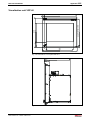
Visualization unit VSP 16 ...................................................................................................... 9-23
Visualization unit VSP 40 ...................................................................................................... 9-25
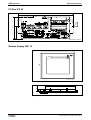
PC-Box IPC 40 ...................................................................................................................... 9-26
Remote display VDP 16 ........................................................................................................ 9-26
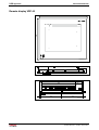
Remote display VDP 40 ........................................................................................................ 9-28
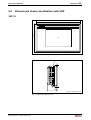
9.6
Dimensional sheets visualization units VEP............................................................................... 9-29
VEP 30................................................................................................................................... 9-29
VEP 40................................................................................................................................... 9-30
VEP 50................................................................................................................................... 9-31
9.7
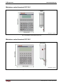
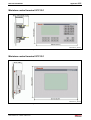
Dimensional sheets miniature control terminals ......................................................................... 9-33
Miniature control terminal VCP 01.1...................................................................................... 9-33
Miniature control terminal VCP 02.1...................................................................................... 9-33
Miniature control terminal VCP 05.1...................................................................................... 9-34
Miniature control terminal VCP 08.1...................................................................................... 9-34
Miniature control terminal VCP 20.1...................................................................................... 9-35
Miniature control terminal VCP 25.1...................................................................................... 9-35
9.8
Dimensional sheets, terminal diagrams drives ........................................................................... 9-36
Option EN1: HSF, resolver .................................................................................................... 9-36
Option EN2: EnDAT2.1, 1 Vss, 5VTTL ................................................................................. 9-36
Option L1: Starting lockout .................................................................................................... 9-38
Option S1: Safety technology I/O .......................................................................................... 9-38
Option MD1: Digital I/O extension ......................................................................................... 9-39
Option MA1: Analog I/O extension ........................................................................................ 9-40
SERCOS interface DSS02.1M .............................................................................................. 9-41
Input / output interface DEA .................................................................................................. 9-42
Encoder interface DAG01.2M (EnDat or SSI interface) ........................................................ 9-44
Analog interface with actual position value output DAE02.1M.............................................. 9-45
Absolute encoder emulator DSA01.1M ................................................................................. 9-46
Position interface for square-wave signals DEF01.1M.......................................................... 9-47
Encoder interface DFF01.1M ................................................................................................ 9-48
High-resolution position interface for sinusoidal signals DLF01.1M...................................... 9-49
Gear wheel encoder interface DZF02.1M ............................................................................. 9-50
Gear wheel encoder interface DZF03.1M ............................................................................. 9-51
Encoder branching DGA01.2................................................................................................. 9-52
9.9
List of connectors and ready-made cables................................................................................. 9-53
9.10 Supplementary documentation ................................................................................................... 9-56
DOK-SYNAX*-SY*-12VRS**-PR01-EN-P
VIII Contents
Rexroth SYNAX 200
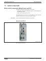
10 Index
10-1
11 Service & Support
11-1
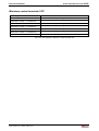
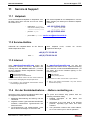
11.1 Helpdesk ..................................................................................................................................... 11-1
11.2 Service-Hotline ........................................................................................................................... 11-1
11.3 Internet........................................................................................................................................ 11-1
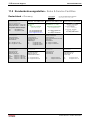
11.4 Vor der Kontaktaufnahme... - Before contacting us... ................................................................ 11-1
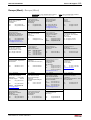
11.5 Kundenbetreuungsstellen - Sales & Service Facilities ............................................................... 11-2
DOK-SYNAX*-SY*-12VRS**-PR01-EN-P
System configurations 1-1
Rexroth SYNAX 200
1
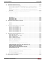
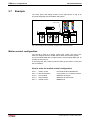
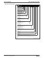
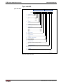
System configurations
1.1
General information
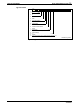
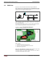
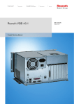
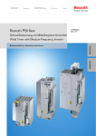
SYNAX 200 systems are built of
•
one or several MotionControls PPC with up to 40 digital intelligent
drives per unit of the DKR, Diax 04, EcoDrive 03, EcoDriveCs or
IndraDrive family,
•
optional PLC or optional PLC integrated in the PPC,
•
optional operator input terminal and visualization units IndraControl V,
•
fiber-optics-cable connection between motion control and drives
meeting SERCOS interface norm (IEC 61491 or EN 61491),
•
a number of optional plug-in cards or option modules for the digital
intelligent drives and option modules for the PPC
•
and I/O components.
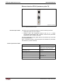
YF000139V01_EN.bmp
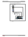
Fig. 1-1: Example SYNAX 200 system
The following describes the system components and the resulting system
structures.
Note:
The SYNAX 200 system is adapted to the hardware on the
machine in two steps:
• First the drive concept in terms of the motor is determined.
This includes drive amplifiers and linear scale (as part of
the basic drive configuration).
• Then PPC motion control function and plug-in card
assignment to the PPC motion controls is determined.
DOK-SYNAX*-SY*-12VRS**-PR01-EN-P
1-2 System configurations
1.2
Rexroth SYNAX 200
System components
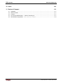
Motion control components (MotionControl and PLC)
The system components of the motion control contain:
• PPC-R bzw. PPC-P as MotionControl system or with integrated PLC
as MotionLogic system,
• option cards for MotionControl or PLC.
The MotionControl and the PLC can be adapted to meet numerous
application requirements by using various option modules.
Basic device
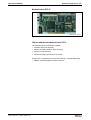
A PPC not fitted with option modules is a basic device.
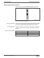
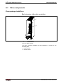
MotionControl PPC-R
YG000049V01_NN.bmp
Fig. 1-2: MotionControl PPC-R
DOK-SYNAX*-SY*-12VRS**-PR01-EN-P
System configurations 1-3
Rexroth SYNAX 200
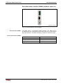
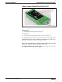
MotionControl PPC-P
YG000003V01_NN.bmp
Fig. 1-3: MotionControl PPC-P
Option modules for MotionControl PPC
The following option modules are available:
• ARCNET-/PPC link assembly,
• fieldbus assembly (fieldbus slave interface),
• master encoder interface
• Ethernet assembly (at PPC-R2x on-board).
Using the PLC integrated in the PPC the following is needed additionally:
• fieldbus assembly (fieldbus master interface)
DOK-SYNAX*-SY*-12VRS**-PR01-EN-P
1-4 System configurations
Rexroth SYNAX 200
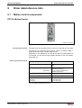
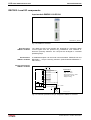
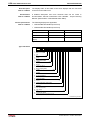
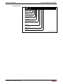
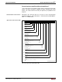
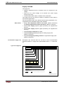
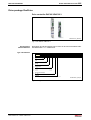
I/O components
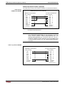
The following I/O components are applicable:
• (Onboard) I/Os directly connected to the motion control
• (Local) I/Os of type series RECO02 directly connected to the motion
control and
• I/Os of type series Rexroth Inline or Rexroth Fieldline connected via
fieldbus.
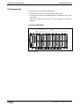
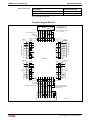
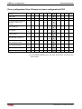
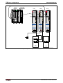
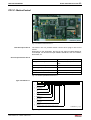
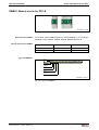
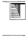
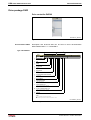
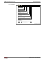
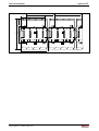
Local I/Os (RECO02)
RECO02
Rexroth
H1
PPC-R22.1
X
8888
X
X
X
2
2
Q*.1.0
1
8
I*.1.0
I*.1.1
I*.1.2
I*.1.3
I*.1.4
I*.1.5
I*.1.6
I*.1.7
9
0V
2
3
4
5
6
7
1
S1
0V
4
Q*.1.1
5
6
7
Q*.1.2
8
Q*.1.3
9
1
Q*.1.4
1
1
Q*.1.5
1
1
Q*.1.6
1
2
3
4
5
6
7
8
9
1
I*.1.0
I*.1.1
I*.1.2
I*.1.3
I*.1.4
I*.1.5
I*.1.6
I*.1.7
0V
0V
1
H2
X
RESET DIST
X
2
X1
U4
3
4
5
6
7
8
COM
PROG
Q1
Q2
I1
I2
I3
24Ve
0Ve
Bb
Bb
24V
0V
U3
X16
9
1
I*.0.0
I*.0.1
I*.0.2
I*.0.3
I*.0.4
I*.0.5
I*.0.6
I*.0.7
0V
0V
4
Q*.0.1
Q*.0.2
Q*.0.3
9
1
Q*.0.4
1
1
Q*.0.5
1
1
Q*.0.6
1
2
3
4
5
6
7
8
9
1
1
6
Q*.1.4
7
Q*.1.5
Q*.1.6
0V
5
9
1
9
4
1
1
8
3
1
S1
0V
I*.0.0
I*.0.1
I*.0.2
I*.0.3
I*.0.4
I*.0.5
I*.0.6
I*.0.7
0V
0V
Q*.0.1
Q*.0.2
Q*.0.3
9
1
Q*.0.4
1
1
Q*.0.5
1
1
1
Q*.0.7
RMA02.2-16-RE230-
RME02.2-16-
8
Q*.1.3
9
Q*.1.4
1
1
Q*.1.5
1
1
Q*.1.6
2
3
4
5
6
7
8
9
1
I*.1.0
I*.1.1
I*.1.2
I*.1.3
I*.1.4
I*.1.5
I*.1.6
I*.1.7
0V
0V
Q*.0.6
8
I*.0.0
I*.0.1
I*.0.2
I*.0.3
I*.0.4
I*.0.5
I*.0.6
I*.0.7
9
0V
2
3
4
5
6
7
1
Q*.0.1
Q*.0.2
Q*.0.3
9
1
Q*.0.4
1
1
Q*.0.5
1
1
1
RME02.2-16-
8
Q*.1.3
9
1
Q*.1.4
1
1
Q*.1.5
1
1
Q*.1.6
8
I*.1.0
I*.1.1
I*.1.2
I*.1.3
I*.1.4
I*.1.5
I*.1.6
I*.1.7
9
0V
2
3
4
5
6
7
S11
0V
Q*.0.6
1
2
3
4
5
6
7
8
9
1
I*.0.0
I*.0.1
I*.0.2
I*.0.3
I*.0.4
I*.0.5
I*.0.6
I*.0.7
0V
0V
Q*.0.1
Q*.0.2
Q*.0.3
Q*.0.4
1
1
Q*.0.5
1
1
1
Q*.0.7
RME02.2-16-
a maximum of 4 module carrier
Q*.1.4
1
1
Q*.1.5
1
1
2
Q*.0.6
I*.0.0
I*.0.1
I*.0.2
I*.0.3
I*.0.4
I*.0.5
I*.0.6
I*.0.7
1
2
3
4
5
6
7
8
9
0V
1
0V
Q*.1.6
Q*.1.7
4
Q*.0.0
Q*.0.1
5
6
Q*.0.2
7
8
Q*.0.3
9
1
Q*.0.4
1
1
Q*.0.5
1
1
Q*.0.6
1
1
RMA02.2-16-RE230-
Q*.1.3
9
1
3
9
1
Q*.1.2
8
1
Q*.0.0
7
8
Q*.1.1
6
7
1
5
6
Q*.1.0
5
X
X
4
4
1
Q*.1.7
3
7
8
Q*.1.2
2
Q*.0.0
5
6
6
7
1
1
1
Q*.0.7
RMA02.2-16-RE230-
0V
4
2
3
Q*.1.1
X
3
1
1
Q*.1.0
5
1
X
2
4
1
Q*.1.7
X
Q*.0.0
7
8
Q*.1.2
1
1
5
6
2
3
6
7
1
X
X
1
Q*.1.1
5
1
Q*.1.7
X
4
4
1
1
1
RME02.2-16-
Q*.1.3
1
X
Q*.1.0
3
I*.1.0
I*.1.1
I*.1.2
I*.1.3
I*.1.4
I*.1.5
I*.1.6
I*.1.7
2
3
7
8
8
2
Q*.0.0
5
6
2
1
1
3
1
U2
X10
Q*.1.2
X
1
TX
RX
6
7
1
X
1
Q*.1.1
5
1
Q*.1.7
X
2
4
1
1
S2
X
Q*.1.0
3
3
U1
X
1
1
S1
1
Q*.0.7
RMA02.2-16-RE230-
RME02.2-16-
Q*.0.7
RMA02.2-16-RE230-
...
YG000004V01_EN.FH7
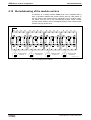
Fig. 1-4: RECO02
DOK-SYNAX*-SY*-12VRS**-PR01-EN-P
System configurations 1-5
Rexroth SYNAX 200
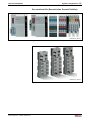
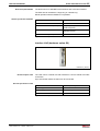
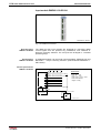
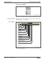
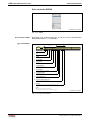
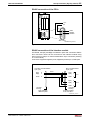
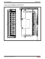
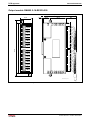
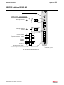
Decentralized I/Os (Rexroth Inline, Rexroth Fieldline)
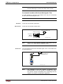
YG000006V02_NN.bmp
Fig. 1-5: Rexroth Inline
YG000007V01_NN.bmp
Fig. 1-6: Rexroth Fieldline
DOK-SYNAX*-SY*-12VRS**-PR01-EN-P
1-6 System configurations
Rexroth SYNAX 200
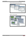
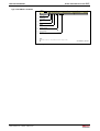
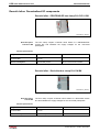
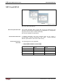
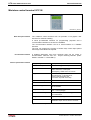
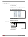
HMI components
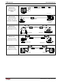
These are the HMI components of the IndraControl V devices:
• PC based operator input terminals BTV, VSP, VSB/VDP, IPC/VDP,
VPP,
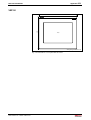
• Windows CE based operator input terminals VEP or
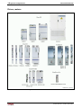
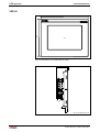
• miniature control terminals (embedded units) VCP.
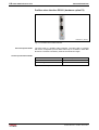
PC based operator input terminals
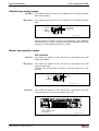
YG000008V02_NN.bmp
Fig. 1-7: PC based operator input terminals BTV, VSP, VSB/VDP, IPC/VDP, VPP
DOK-SYNAX*-SY*-12VRS**-PR01-EN-P
System configurations 1-7
Rexroth SYNAX 200
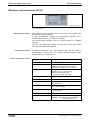
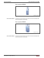
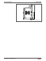
Windows CE based operator input terminals
YG000067V01_NN.bmp
Fig. 1-8: Windows CE based operator input terminals VEP
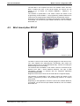
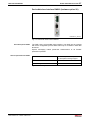
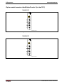
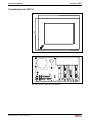
Miniature control terminals
YG000046V02_NN.bmp
Fig. 1-9: Miniature control terminals VCP
DOK-SYNAX*-SY*-12VRS**-PR01-EN-P
1-8 System configurations
Rexroth SYNAX 200
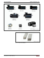
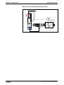
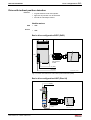
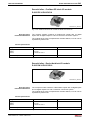
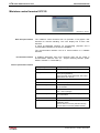
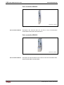
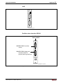
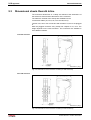
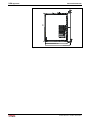
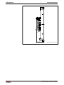
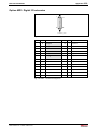
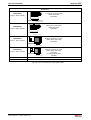
Drives, motors
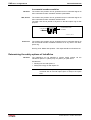
YG000010V01_NN.bmp
Fig. 1-10: Drive controller
DOK-SYNAX*-SY*-12VRS**-PR01-EN-P
System configurations 1-9
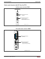
Rexroth SYNAX 200
YG000011V02_NN.bmp
Fig. 1-11: Rotary motors
YG000012V02_NN.bmp
Fig. 1-12: Linear motors IndraDyn L
DOK-SYNAX*-SY*-12VRS**-PR01-EN-P
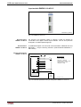
1-10 System configurations
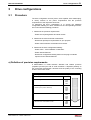
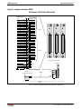
1.3
Rexroth SYNAX 200
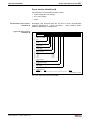
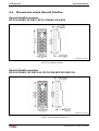
System structures
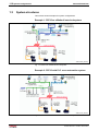
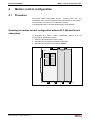
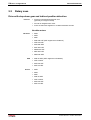
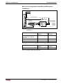
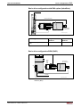
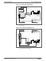
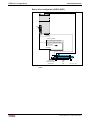
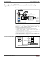
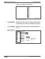
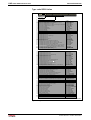
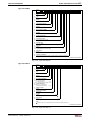
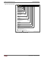
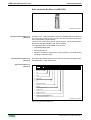
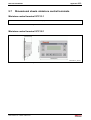
This section shows examples for system configurations.
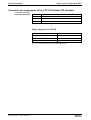
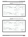
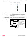
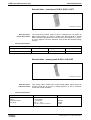
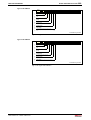
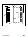
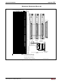
Example 1: PPC-R as a MotionControl subsystem
YF000140V02_EN.bmp
Fig. 1-13: PPC-R as a MotionControl subsystem
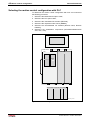
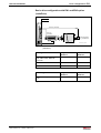
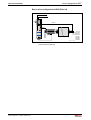
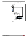
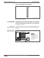
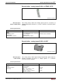
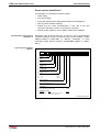
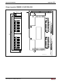
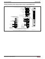
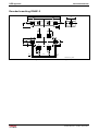
Example 2: PPC-R with PLC as an automation system
YF000141V02_EN.bmp
Fig. 1-14: PPC-R with PLC as a stand alone automation system
DOK-SYNAX*-SY*-12VRS**-PR01-EN-P
System configurations 1-11
Rexroth SYNAX 200
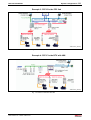
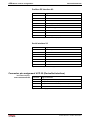
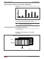
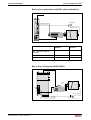
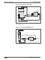
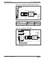
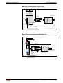
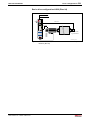
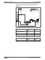
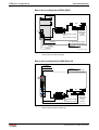
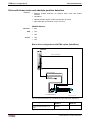
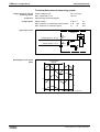
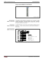
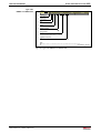
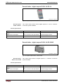
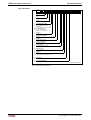
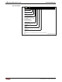
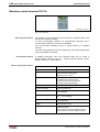
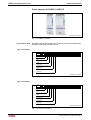
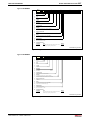
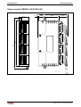
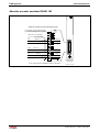
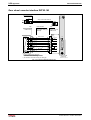
Example 3: PPC-R in the PPC link
YF000142V01_EN.bmp
Fig. 1-15: PPC-R in the PPC link
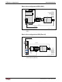
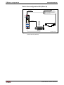
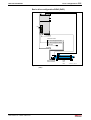
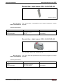
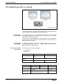
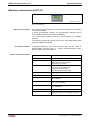
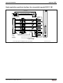
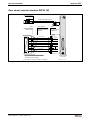
Example 4: PPC-P in the BTV with HMI
YF000143V01_EN.bmp
Fig. 1-16: PPC-P in the BTV with HMI
DOK-SYNAX*-SY*-12VRS**-PR01-EN-P
1-12 System configurations
Rexroth SYNAX 200
DOK-SYNAX*-SY*-12VRS**-PR01-EN-P
Important directions for use 2-1
Rexroth SYNAX 200
2
Important directions for use
2.1
Appropriate use
Introduction
Rexroth products represent state-of-the-art developments and
manufacturing. They are tested prior to delivery to ensure operating safety
and reliability.
The products may only be used in the manner that is defined as
appropriate. If they are used in an inappropriate manner, then situations
can develop that may lead to property damage or injury to personnel.
Note:
Bosch Rexroth, as manufacturer, is not liable for any damages
resulting from inappropriate use. In such cases, the guarantee
and the right to payment of damages resulting from
inappropriate use are forfeited. The user alone carries all
responsibility of the risks.
Before using Rexroth products, make sure that all the pre-requisites for
appropriate use of the products are satisfied:
• Personnel that in any way, shape or form uses our products must first
read and understand the relevant safety instructions and be familiar
with appropriate use.
• If the product takes the form of hardware, then they must remain in
their original state, in other words, no structural changes are permitted.
It is not permitted to decompile software products or alter source
codes.
• Do not mount damaged or faulty products or use them in operation.
• Make sure that the products have been installed in the manner
described in the relevant documentation.
DOK-SYNAX*-SY*-12VRS**-PR01-EN-P
2-2 Important directions for use
Rexroth SYNAX 200
Areas of use and application
SYNAX 200 made by Bosch Rexroth is designed for the synchronization
of machine axes (shaftless machines).
Control and monitoring of the drive system may require additional sensors
and actors.
Note:
The components may only be used with the accessories and
parts specified in this document. If a component has not been
specifically named, then it may not be either mounted or
connected. The same applies to cables and lines.
Operation is only permitted in the specified configurations and
combinations of components using the software and firmware
as specified in the relevant function descriptions.
The motion control and every drive controller has to be parameterized/
programmed before starting it up, making it possible for the motor to
execute the specific functions of an application.
The motion control solution SYNAX 200 has been developed for use in
single or multiple-axis drives and control tasks.
Typical applications of SYNAX 200 are:
•
printing and paper converting machines,
•
textile machines,
•
handling and assembly systems and
•
packaging and foodstuff machines.
The motion control and drive system may only be operated under the
assembly, installation and ambient conditions as described here
(temperature, system of protection, humidity, EMC requirements, etc.)
and in the position specified.
2.2
Inappropriate use
Using the SYNAX 200 components outside of the above-referenced areas
of application or under operating conditions other than described in the
document and the technical data specified is defined as “inappropriate
use".
The SYNAX 200 components may not be used if
•
they are subject to operating conditions that do not meet the above
specified ambient conditions. This includes, for example, operation
under water, in the case of extreme temperature fluctuations or
extremely high maximum temperatures or if
•
Rexroth has not specifically released them for that intended purpose.
Please note the specifications outlined in the general Safety
Guidelines!
DOK-SYNAX*-SY*-12VRS**-PR01-EN-P
Safety Instructions for Electric Drives and Controls 3-1
Rexroth SYNAX 200
3
Safety Instructions for Electric Drives and Controls
3.1
Introduction
Read these instructions before the initial startup of the equipment in order
to eliminate the risk of bodily harm or material damage. Follow these
safety instructions at all times.
Do not attempt to install or start up this equipment without first reading all
documentation provided with the product. Read and understand these
safety instructions and all user documentation of the equipment prior to
working with the equipment at any time. If you do not have the user
documentation for your equipment, contact your local Bosch Rexroth
representative to send this documentation immediately to the person or
persons responsible for the safe operation of this equipment.
If the equipment is resold, rented or transferred or passed on to others,
then these safety instructions must be delivered with the equipment.
WARNING
3.2
Improper use of this equipment, failure to follow
the safety instructions in this document or
tampering with the product, including disabling
of safety devices, may result in material
damage, bodily harm, electric shock or even
death!
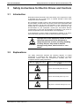
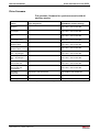
Explanations
The safety instructions describe the following degrees of hazard
seriousness in compliance with ANSI Z535. The degree of hazard
seriousness informs about the consequences resulting from noncompliance with the safety instructions.
Warning symbol with signal
word
Degree of hazard seriousness according
to ANSI
Death or severe bodily harm will occur.
DANGER
Death or severe bodily harm may occur.
WARNING
Bodily harm or material damage may occur.
CAUTION
Fig. 3-1:
DOK-SYNAX*-SY*-12VRS**-PR01-EN-P
Hazard classification (according to ANSI Z535)
3-2 Safety Instructions for Electric Drives and Controls
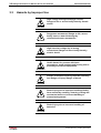
3.3
Rexroth SYNAX 200
Hazards by Improper Use
High voltage and high discharge current!
Danger to life or severe bodily harm by electric
shock!
DANGER
Dangerous movements! Danger to life, severe
bodily harm or material damage by
unintentional motor movements!
DANGER
High electrical voltage due to wrong
connections! Danger to life or bodily harm by
electric shock!
WARNING
Health hazard for persons with heart
pacemakers, metal implants and hearing aids in
proximity to electrical equipment!
WARNING
Surface of machine housing could be extremely
hot! Danger of injury! Danger of burns!
CAUTION
CAUTION
Risk of injury due to improper handling! Bodily
harm caused by crushing, shearing, cutting and
mechanical shock or incorrect handling of
pressurized systems!
Risk of injury due to incorrect handling of
batteries!
CAUTION
DOK-SYNAX*-SY*-12VRS**-PR01-EN-P
Safety Instructions for Electric Drives and Controls 3-3
Rexroth SYNAX 200
3.4
General Information
• Bosch Rexroth AG is not liable for damages resulting from failure to
observe the warnings provided in this documentation.
• Read the operating, maintenance and safety instructions in your
language before starting up the machine. If you find that you cannot
completely understand the documentation for your product, please ask
your supplier to clarify.
• Proper and correct transport, storage, assembly and installation as
well as care in operation and maintenance are prerequisites for
optimal and safe operation of this equipment.
• Only persons who are trained and qualified for the use and operation
of the equipment may work on this equipment or within its proximity.
• The persons are qualified if they have sufficient knowledge of the
assembly, installation and operation of the equipment as well as an
understanding of all warnings and precautionary measures noted in
these instructions.
• Furthermore, they must be trained, instructed and qualified to
switch electrical circuits and equipment on and off in accordance
with technical safety regulations, to ground them and to mark them
according to the requirements of safe work practices. They must
have adequate safety equipment and be trained in first aid.
• Only use spare parts and accessories approved by the manufacturer.
• Follow all safety regulations and requirements for the specific
application as practiced in the country of use.
• The equipment is designed for installation in industrial machinery.
• The ambient conditions given in the product documentation must be
observed.
• Use only safety features and applications that are clearly and explicitly
approved in the Project Planning Manual.
For example, the following areas of use are not permitted: construction
cranes, elevators used for people or freight, devices and vehicles to
transport people, medical applications, refinery plants, transport of
hazardous goods, nuclear applications, applications sensitive to high
frequency, mining, food processing, control of protection equipment
(also in a machine).
• The information given in the documentation of the product with regard
to the use of the delivered components contains only examples of
applications and suggestions.
The machine and installation manufacturer must
• make sure that the delivered components are suited for his
individual application and check the information given in this
documentation with regard to the use of the components,
• make sure that his application complies with the applicable safety
regulations and standards and carry out the required measures,
modifications and complements.
• Startup of the delivered components is only permitted once it is sure
that the machine or installation in which they are installed complies
with the national regulations, safety specifications and standards of the
application.
DOK-SYNAX*-SY*-12VRS**-PR01-EN-P
3-4 Safety Instructions for Electric Drives and Controls
Rexroth SYNAX 200
• Operation is only permitted if the national EMC regulations for the
application are met.
The instructions for installation in accordance with EMC requirements
can be found in the documentation "EMC in Drive and Control
Systems".
The machine or installation manufacturer is responsible for
compliance with the limiting values as prescribed in the national
regulations.
• Technical data, connections and operational conditions are specified in
the product documentation and must be followed at all times.
DOK-SYNAX*-SY*-12VRS**-PR01-EN-P
Safety Instructions for Electric Drives and Controls 3-5
Rexroth SYNAX 200
3.5
Protection Against Contact with Electrical Parts
Note:
This section refers to equipment and drive components with
voltages above 50 Volts.
Touching live parts with voltages of 50 Volts and more with bare hands or
conductive tools or touching ungrounded housings can be dangerous and
cause electric shock. In order to operate electrical equipment, certain
parts must unavoidably have dangerous voltages applied to them.
High electrical voltage! Danger to life, severe
bodily harm by electric shock!
DANGER
DOK-SYNAX*-SY*-12VRS**-PR01-EN-P
⇒ Only those trained and qualified to work with or on
electrical equipment are permitted to operate, maintain
or repair this equipment.
⇒ Follow general construction and safety regulations when
working on high voltage installations.
⇒ Before switching on power the ground wire must be
permanently connected to all electrical units according
to the connection diagram.
⇒ Do not operate electrical equipment at any time, even
for brief measurements or tests, if the ground wire is not
permanently connected to the points of the components
provided for this purpose.
⇒ Before working with electrical parts with voltage higher
than 50 V, the equipment must be disconnected from
the mains voltage or power supply. Make sure the
equipment cannot be switched on again unintended.
⇒ The following should be observed with electrical drive
and filter components:
⇒ Wait five (5) minutes after switching off power to allow
capacitors to discharge before beginning to work.
Measure the voltage on the capacitors before beginning
to work to make sure that the equipment is safe to
touch.
⇒ Never touch the electrical connection points of a
component while power is turned on.
⇒ Install the covers and guards provided with the
equipment properly before switching the equipment on.
Prevent contact with live parts at any time.
⇒ A residual-current-operated protective device (RCD)
must not be used on electric drives! Indirect contact
must be prevented by other means, for example, by an
overcurrent protective device.
⇒ Electrical components with exposed live parts and
uncovered high voltage terminals must be installed in a
protective housing, for example, in a control cabinet.
3-6 Safety Instructions for Electric Drives and Controls
Rexroth SYNAX 200
To be observed with electrical drive and filter components:
High electrical voltage on the housing!
High leakage current! Danger to life, danger of
injury by electric shock!
DANGER
3.6
⇒ Connect the electrical equipment, the housings of all
electrical units and motors permanently with the safety
conductor at the ground points before power is
switched on. Look at the connection diagram. This is
even necessary for brief tests.
⇒ Connect the safety conductor of the electrical
equipment always permanently and firmly to the
supply mains. Leakage current exceeds 3.5 mA in
normal operation.
⇒ Use a copper conductor with at least 10 mm² cross
section over its entire course for this safety conductor
connection!
⇒ Prior to startups, even for brief tests, always connect
the protective conductor or connect with ground wire.
Otherwise, high voltages can occur on the housing
that lead to electric shock.
Protection Against Electric Shock by Protective Low
Voltage (PELV)
All connections and terminals with voltages between 0 and 50 Volts on
Rexroth products are protective low voltages designed in accordance with
international standards on electrical safety.
High electrical voltage due to wrong
connections! Danger to life, bodily harm by
electric shock!
WARNING
⇒ Only connect equipment, electrical components and
cables of the protective low voltage type (PELV =
Protective Extra Low Voltage) to all terminals and
clamps with voltages of 0 to 50 Volts.
⇒ Only electrical circuits may be connected which are
safely isolated against high voltage circuits. Safe
isolation is achieved, for example, with an isolating
transformer, an opto-electronic coupler or when
battery-operated.
DOK-SYNAX*-SY*-12VRS**-PR01-EN-P
Rexroth SYNAX 200
3.7
Safety Instructions for Electric Drives and Controls 3-7
Protection Against Dangerous Movements
Dangerous movements can be caused by faulty control of the connected
motors. Some common examples are:
• improper or wrong wiring of cable connections
• incorrect operation of the equipment components
• wrong input of parameters before operation
• malfunction of sensors, encoders and monitoring devices
• defective components
• software or firmware errors
Dangerous movements can occur immediately after equipment is
switched on or even after an unspecified time of trouble-free operation.
The monitoring in the drive components will normally be sufficient to avoid
faulty operation in the connected drives. Regarding personal safety,
especially the danger of bodily injury and material damage, this alone
cannot be relied upon to ensure complete safety. Until the integrated
monitoring functions become effective, it must be assumed in any case
that faulty drive movements will occur. The extent of faulty drive
movements depends upon the type of control and the state of operation.
DOK-SYNAX*-SY*-12VRS**-PR01-EN-P
3-8 Safety Instructions for Electric Drives and Controls
Rexroth SYNAX 200
Dangerous movements! Danger to life, risk of
injury, severe bodily harm or material damage!
DANGER
⇒ Ensure personal safety by means of qualified and
tested higher-level monitoring devices or measures
integrated in the installation. Unintended machine
motion is possible if monitoring devices are disabled,
bypassed or not activated.
⇒ Pay attention to unintended machine motion or other
malfunction in any mode of operation.
⇒ Keep free and clear of the machine’s range of motion
and moving parts. Possible measures to prevent
people from accidentally entering the machine’s range
of motion:
- use safety fences
- use safety guards
- use protective coverings
- install light curtains or light barriers
⇒ Fences and coverings must be strong enough to
resist maximum possible momentum, especially if
there is a possibility of loose parts flying off.
⇒ Mount the emergency stop switch in the immediate
reach of the operator. Verify that the emergency stop
works before startup. Don’t operate the machine if the
emergency stop is not working.
⇒ Isolate the drive power connection by means of an
emergency stop circuit or use a starting lockout to
prevent unintentional start.
⇒ Make sure that the drives are brought to a safe
standstill before accessing or entering the danger
zone. Safe standstill can be achieved by switching off
the power supply contactor or by safe mechanical
locking of moving parts.
⇒ Secure vertical axes against falling or dropping after
switching off the motor power by, for example:
- mechanically securing the vertical axes
- adding an external braking/ arrester/ clamping
mechanism
- ensuring sufficient equilibration of the vertical axes
The standard equipment motor brake or an external
brake controlled directly by the drive controller are
not sufficient to guarantee personal safety!
DOK-SYNAX*-SY*-12VRS**-PR01-EN-P
Safety Instructions for Electric Drives and Controls 3-9
Rexroth SYNAX 200
⇒ Disconnect electrical power to the equipment using a
master switch and secure the switch against
reconnection for:
- maintenance and repair work
- cleaning of equipment
- long periods of discontinued equipment use
⇒ Prevent the operation of high-frequency, remote
control and radio equipment near electronics circuits
and supply leads. If the use of such equipment cannot
be avoided, verify the system and the installation for
possible malfunctions in all possible positions of
normal use before initial startup. If necessary, perform
a special electromagnetic compatibility (EMC) test on
the installation.
3.8
Protection Against Magnetic and Electromagnetic Fields
During Operation and Mounting
Magnetic and electromagnetic fields generated near current-carrying
conductors and permanent magnets in motors represent a serious health
hazard to persons with heart pacemakers, metal implants and hearing
aids.
Health hazard for persons with heart
pacemakers, metal implants and hearing aids in
proximity to electrical equipment!
WARNING
⇒ Persons with heart pacemakers, hearing aids and
metal implants are not permitted to enter the following
areas:
- Areas in which electrical equipment and parts are
mounted, being operated or started up.
- Areas in which parts of motors with permanent
magnets are being stored, operated, repaired or
mounted.
⇒ If it is necessary for a person with a heart pacemaker
to enter such an area, then a doctor must be
consulted prior to doing so. Heart pacemakers that
are already implanted or will be implanted in the
future, have a considerable variation in their electrical
noise immunity. Therefore there are no rules with
general validity.
⇒ Persons with hearing aids, metal implants or metal
pieces must consult a doctor before they enter the
areas described above. Otherwise, health hazards will
occur.
DOK-SYNAX*-SY*-12VRS**-PR01-EN-P
3-10 Safety Instructions for Electric Drives and Controls
3.9
Rexroth SYNAX 200
Protection Against Contact with Hot Parts
Housing surfaces could be extremely hot!
Danger of injury! Danger of burns!
CAUTION
⇒ Do not touch housing surfaces near sources of heat!
Danger of burns!
⇒ After switching the equipment off, wait at least ten (10)
minutes to allow it to cool down before touching it.
⇒ Do not touch hot parts of the equipment, such as
housings with integrated heat sinks and resistors.
Danger of burns!
3.10 Protection During Handling and Mounting
Under certain conditions, incorrect handling and mounting of parts and
components may cause injuries.
Risk of injury by incorrect handling! Bodily
harm caused by crushing, shearing, cutting and
mechanical shock!
CAUTION
⇒ Observe general installation and safety instructions
with regard to handling and mounting.
⇒ Use appropriate mounting and transport equipment.
⇒ Take precautions to avoid pinching and crushing.
⇒ Use only appropriate tools. If specified by the product
documentation, special tools must be used.
⇒ Use lifting devices and tools correctly and safely.
⇒ For safe protection wear appropriate protective
clothing, e.g. safety glasses, safety shoes and safety
gloves.
⇒ Never stand under suspended loads.
⇒ Clean up liquids from the floor immediately to prevent
slipping.
DOK-SYNAX*-SY*-12VRS**-PR01-EN-P
Safety Instructions for Electric Drives and Controls 3-11
Rexroth SYNAX 200
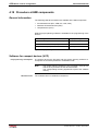
3.11 Battery Safety
Batteries contain reactive chemicals in a solid housing. Inappropriate
handling may result in injuries or material damage.
Risk of injury by incorrect handling!
CAUTION
Note:
⇒ Do not attempt to reactivate discharged batteries by
heating or other methods (danger of explosion and
cauterization).
⇒ Never charge non-chargeable batteries (danger of
leakage and explosion).
⇒ Never throw batteries into a fire.
⇒ Do not dismantle batteries.
⇒ Do not damage electrical components installed in the
equipment.
Be aware of environmental protection and disposal! The
batteries contained in the product should be considered as
hazardous material for land, air and sea transport in the sense
of the legal requirements (danger of explosion). Dispose
batteries separately from other waste. Observe the legal
requirements in the country of installation.
3.12 Protection Against Pressurized Systems
Certain motors and drive controllers, corresponding to the information in
the respective Project Planning Manual, must be provided with
pressurized media, such as compressed air, hydraulic oil, cooling fluid
and cooling lubricant supplied by external systems. Incorrect handling of
the supply and connections of pressurized systems can lead to injuries or
accidents. In these cases, improper handling of external supply systems,
supply lines or connections can cause injuries or material damage.
Danger of injury by incorrect handling of
pressurized systems !
CAUTION
Note:
DOK-SYNAX*-SY*-12VRS**-PR01-EN-P
⇒ Do not attempt to disassemble, to open or to cut a
pressurized system (danger of explosion).
⇒ Observe the operation instructions of the respective
manufacturer.
⇒ Before disassembling pressurized systems, release
pressure and drain off the fluid or gas.
⇒ Use suitable protective clothing (for example safety
glasses, safety shoes and safety gloves)
⇒ Remove any fluid that has leaked out onto the floor
immediately.
Environmental protection and disposal! The media used in the
operation of the pressurized system equipment may not be
environmentally compatible. Media that are damaging the
environment must be disposed separately from normal waste.
Observe the legal requirements in the country of installation.
3-12 Safety Instructions for Electric Drives and Controls
Rexroth SYNAX 200
Notes
DOK-SYNAX*-SY*-12VRS**-PR01-EN-P
Motion control configuration 4-1
Rexroth SYNAX 200
4
Motion control configuration
4.1
Procedure
The motion control configuration choices (motion control, PLC, I/O,
visualization units) conform to the functional requirements on the system.
In particular the use of the PLC is a decisively criterion.
In the appendix there's a list with supplementary documentation.
Selecting the motion control configuration without PLC (MotionControl
subsystem)
To determine the motion control configuration without PLC we
recommend the following procedure:
1. determine the MotionControl option cards,
2. determine the centralized I/O modules (RECO02),
3. determine the required module carrier (RMB02).
module carrier
PPC
firmware
local I/O
option
cards
YF000154V01_EN.FH7
Fig. 4-1: Motion control configuration without PLC
DOK-SYNAX*-SY*-12VRS**-PR01-EN-P
4-2 Motion control configuration
Rexroth SYNAX 200
Selecting the motion control configuration with PLC
To determine the motion control configuration with PLC we recommend
the following procedure:
1. determine the MotionControl option cards,
2. determine the PLC option cards,
3. determine the centralized I/O modules (RECO02),
4. determine the required module carrier (RMB02),
5. determine the decentralized I/O modules (Rexroth Inline, Rexroth
Fieldline),
6. determine the visualization components (BTV/VSP/VSB/IPC/VDP/
VPP, VEP, VCP).
visualization (VCP / VEP / BTV...)
module carrier
PPC
lokale E/A
firmware
option
card
decentralized I/O (Rexroth Inline/Fieldline)
YF000155V01_EN.FH7
Fig. 4-2: Motion control configuration with PLC
DOK-SYNAX*-SY*-12VRS**-PR01-EN-P
Motion control configuration 4-3
Rexroth SYNAX 200
Selecting the firmware
The PPC control can be fitted with different SYNAX firmware options:
Option
Firmware designation
MotionControl option
FWA-PPCPR*-SY*-...
MotionLogic option
FWA-PPCPR*-SL*-...
MotionLogic option "economic"
FWA-PPCPR*-SLE-...
Fig. 4-3: SYNAX firmware options
Properties of the MotionControl option SY*
• full MotionControl functionality
• I/O logic instead of integrated PLC
Properties of the MotionLogic option SL*
• full MotionControl functionality
• integrated PLC IndraLogic
Properties of the MotionLogic option SLE
• reduced MotionControl functionality
• integrated PLC IndraLogic
Reduced MotionControl functionality at SLE option
The differences of the reduced MotionControl functionality at the SLE
option is displayed in the following table:
Functionality
Reduced functionality at SLE
Full functionality at SY* and SL*
Number of axes
a maximum of 8
a maximum of 40
Process controller tension
controller/winding controller
a maximum of 4
no restrictions
Process controller register controller
not supported
a maximum of 16
Extension options of the PPC
a maximum of 2
a maximum of 3
Fieldbus master options of the PPC
not supported
Profibus and DeviceNet master
Fieldbus slave options of the PPC
Profibus, DeviceNet and Ethernet/IP
slave
Profibus, DeviceNet and Ethernet/IP
slave
Master encoder option of the PPC
not supported
is supported
Fig. 4-4: MotionControl functionality
DOK-SYNAX*-SY*-12VRS**-PR01-EN-P
4-4 Motion control configuration
MotionControl PPC-R
14
Rexroth
1
H1
8
S1
2
1
PPC-R22.1
8888
2
3
U1
8
9
Optional slot
5
6
3
S2
5
7
H2
RESET DIST
TX
RX
X1
7
Q1
Q2
I1
I2
I3
24Ve
0Ve
Bb
Bb
24V
0V
U3
X16
U2
X10
U4
10
COM
6
13
11
12
Key for display switchover
or other usage
Slot for the PC card-compatible
firmware module
Reset key S2
Distortion display H2
for SERCOS interface
Fibre-optic emitter
for SERCOS interface
Fibre-optic receiver
for SERCOS interface
X1 voltage supply and
watchdog
Status display H1
4
9
4
PROG
4.2
Rexroth SYNAX 200
10
X16 Programming interface (COM)
11
X10 Serial interface (PROG)
12
Earthing bolt
13
X15 BT bus for connecting
up to 6 devices (PLC only)
14
Ethernet connection
YG000068V01_EN..FH7
PPC-R22.1
Fig. 4-5: PPC-R22.1
The PPC-R unit is a powerful controller in a small size in IP 20 rating. It is
a general-purpose platform that works as a PLC or as a NC controller,
depending on the application and the loaded software.
The PPC-R unit exists with two enclosure versions of different width. A
single-width version and a double-width version.
The two interfaces that are available on the controller are fully connected
according to the Rexroth standard (SIS = Serial Indramat Interface). The
data transfer type (function) is only selected by the related application
(RS232/RS422/RS485). With PPC-R21, the COM interface is brought out
via a separate slot plate if this has not yet been assigned for a different
purpose (by the PC/104 fieldbus, for example).
To install the PPC-R unit, a module carrier system is used that consists of
one or several RMB02.2-04 units. The double carrier RMB02.2-02 can
only be used as an installation carrier. It is merely used for fixing the
PPC-R units; RECO modules cannot be controlled. Interconnecting
several PPC-R units via a backplane is not possible either.
DOK-SYNAX*-SY*-12VRS**-PR01-EN-P
Motion control configuration 4-5
Rexroth SYNAX 200
The PPC-R21.1 unit occupies one slot in the module carrier; the PPCR22.1 occupies two units. In this carrier system, the PPC-R unit can
handle up to 15 further I/O modules (RME02.2..., RMA02.2... or
RMC02.2...).
The firmware or parameters of the motion control are stored on the
programming module PFM01.1. The programming module PSM has PC
card format, the programming module PFM has compact flash format.
Depending on the application, the PPC-R has PC/104 modules fitted that,
for example, can be used for open fieldbus interfaces, such as Profibus,
DeviceNet, etc..
4.3
Brief description PPC-P
YG000052V01_NN.bmp
Fig. 4-6: PPC-P01.1
The PPC-P control in PCI format is directly plugged to a PCI slot of a PC.
The card supports the "plug-and-play" functionality, that means the
address range in the PC is allocated dynamically. Jumpers for setting the
address range are not necessary.
The interface that is available on the motion control is connected as per
Rexroth norm (SIS = Serial Indramat Interface). The type of data
transmission (function) is selected with the respective application
(RS232/RS422/RS485).
Diagnosis of the motion control can be read with the 7 segment display.
The firmware or parameters of the motion control are stored on the
PFM01.1 programming module. The programming module is in compact
flash format.
Depending on the application, the PPC-P has PC104 modules fitted that,
for example, can be used for open fieldbus interfaces, such as Profibus,
DeviceNet, etc.
DOK-SYNAX*-SY*-12VRS**-PR01-EN-P
4-6 Motion control configuration
4.4
Rexroth SYNAX 200
Brief description option cards
There are different option cards for the PPC-R and PPC-P. These options
cards are allocated either to the MotionControl or to the PLC. The
following table shows the combination possibilities between option cards
and the type of motion control.
Option card
PPC with MotionControl
PPC with MotionControl and PLC
Profibus-DP Slave (option P2)
X
X
DeviceNet-Slave (option V2)
X
X
Ethernet/IP-Slave (option T2)
X (PPC-R21, PPC-R22 on-board)
X (PPC-R21, PPC-R22 on-board)
Ethernet (option T2)
X (PPC-R21, PPC-R22 on-board)
X (PPC-R21, PPC-R22 on-board)
PPC link (option Q1)
X
X
Master encoder interface (option G2)
X
X
Profibus-DP-Master (option P1)
X
DeviceNet-Master (option V1)
X
Fig. 4-7: Combination possibilities option cards - type of motion control
Option cards for the MotionControl
Profibus-DP slave (option P2, option card DPS01)
The option card DPS01 offers a Profibus-DP slave interface.
Transmission rates of up to 12 Mbit/s are supported.
The functionality contains
•
cyclic transmission of binary I/O data, word and double-word
parameters,
•
non-cyclic transmission of all parameters and I/O data (proprietary
RIN protocol, so called parameter channel),
•
the support of a bus length of 32 words. With the help of a so called
multiplex channel, parts of the cyclic transmission can be multiplexed,
to transmit further data.
DeviceNet slave (option V2, option card DNS03)
The option card DNS03 offers a DeviceNet slave interface.
Transmission rates of up to 500 kbit/s are supported.
The functionality contains
•
cyclic transmission of binary I/O data, word and double-word
parameters (implicit messaging),
•
non-cyclic transmission of all parameters and I/O data (proprietary
RIN protocol within the explicit messaging),
•
the support of a bus length of 32 words. With the help of a so called
multiplex channel, parts of the cyclic transmission can be multiplexed,
to transmit further data.
DOK-SYNAX*-SY*-12VRS**-PR01-EN-P
Motion control configuration 4-7
Rexroth SYNAX 200
Ethernet/IP slave or Ethernet (option T2, option card
ETH01)
ETH01 only with PPC-P11
The option card EHT01 offers a Ethernet/IP slave or a Ethernet interface.
It can only be used with PPC-P11, with PPC-R21 and PPC-R22 the
functionality is on-board.
A transmission rate of 10 MBit/s is supported.
The functionality contains
Ethernet on-board with PPC-R21
and PPC-R22
•
Ethernet/IP slave with cyclic transmission of binary I/O data, word and
double word parameters or cyclic transmission of binary I/O data,
word and double word parameters (within UDP/IP) of 4 different
Ethernet master (PLC),
•
Ethernet/IP slave with non-cyclic transmission of all parameters and
I/O data of 1 Ethernet/IP master or proprietary RIN protocol within
TCP/IP with 4 different Ethernet master (PLC),
•
non-cyclic transmission of all parameters (proprietary RIN protocol
within TCP/IP) of 7 different Ethernet master (SynTop, HMI),
•
the support of a bus length of 32 words. With the help of the so called
multiplex channel, parts of the cyclic transmission can be multiplexed,
to transmit further data.
With PPC-R21 and the PPC-R22 the Ethernet interface is on-board.
The same features are supported as with interface option T2 (ETH01),
10/100 MBit/s is supported as transmission rate.
PPC link (option Q1, option card DAQ03)
Several PPC motion controls can be combined to create one PPC link.
The PPC link makes it possible to assign following axes to different
master axis.
Up to 32 PPC motion controls can be combined to one PPC link.
The combination of PPC motion controls is accomplished with the help of
the plug-in card DAQ. All DAQ assemblies are connected with a fibreoptics cable ring thereby creating the PPC link.
The communication within the PPC link implements, as does the SYNAX
200 ring, a fibre-optics cable ring.
The PPC link can be built on a single or a double fibre-optics-cable ring.
DOK-SYNAX*-SY*-12VRS**-PR01-EN-P
4-8 Motion control configuration
Rexroth SYNAX 200
PPC link (option Q2, option card DAQ04)
Several PPC motion controls can be combined to create one PPC link.
The PPC link makes it possible to assign following axes to different
master axis.
Up to 64 PPC motion controls can be combined to one PPC link.
The combination of PPC motion controls is accomplished with the help of
the plug-in card DAQ. All DAQ assemblies are connected with a fibreoptics cable ring thereby creating the PPC link.
The communication within the PPC link implements, as does the SYNAX
200 ring, a fibre-optics cable ring.
The PPC link can be built on a single or a double fibre-optics-cable ring.
Note:
It is not possible to link controls with option Q2 (DAQ04) and
option Q1 (DAQ03).
Master encoder interface (option G2 option card LAG)
The option card LAG offers the possibility to connect master encoders.
Up to two EnDat master encoders can be connected.
The master encoder can be used by the PPC master axis functionality
"real master axis" as master encoder.
Option Cards for the PLC
Profibus-DP master (option P1, option card DPM01)
The option card DPM01 offers a Profibus-DP master interface.
Transmission rates of up to 12 Mbit/s are supported.
The functionality contains
•
cyclic transmission of binary I/O data, word and double word
parameters,
•
the support of a bus length of 256 words,
•
the support of up to 125 participants per configuration with up to 32
participants per bus segment.
DeviceNet master (option V1, option card DNM03)
The option card DNM03 offers a DeviceNet master interface.
Transmission rates of up to 500 kbit/s are supported.
The functionality contains
•
cyclic transmission of binary I/O data, word and double word
parameters,
•
the support of a bus length of 256 words.
DOK-SYNAX*-SY*-12VRS**-PR01-EN-P
Motion control configuration 4-9
Rexroth SYNAX 200
4.5
Brief description RECO02: local I/O components
YG000047V01_NN.bmp
Fig. 4-8:
Overview RECO02
The I/O components RECO02 serve for the connection of inputs/output
on control side. Digital and analog input and output modules with different
input and output voltage ranges are available .
The inputs or outputs are managed and addressed by the MotionControl
or the PLC.
The following digital input modules are available:
Module
Description
RME02.2-16-DC024
16 inputs, 24 VDC
RME02.2-32-DC024
32 inputs, 24 VDC
RME02.2-16-AC115
16 inputs, 115 VAC
Fig. 4-9: RECO02 digital input modules
The following digital output modules are available:
Module
Description
RMA02.2-16-DC024-200
16 outputs, 24 VDC, 2 A
RMA02.2-32-DC024-050
32 outputs, 24 VDC, 500 mA
RMA02.2-16-AC230-200
16 outputs, 230 VAC, 2A
RMA02.2-16-RE230-200
16 outputs, relay 230 Veff
Fig. 4-10: RECO02 digital output modules
The following analog input/output modules are available:
Module
Description
RMC02.2-2E-1A
2 inputs, 10V; 1 output, 10V
Fig. 4-11: RECO02 analog input/output modules
DOK-SYNAX*-SY*-12VRS**-PR01-EN-P
4-10 Motion control configuration
4.6
Rexroth SYNAX 200
Brief description Rexroth Inline: decentralized I/O
components
YG000006V01_NN.bmp
Fig. 4-12: Rexroth Inline
The I/O components Rexroth Inline serve for the connection via the
fieldbusses Profibus and DeviceNet.
The following modules are available:
• Profibus and DeviceNet fieldbus coupling modules,
• digital and analog input/output modules with different input/output
voltage ranges,
• counting modules and
• block I/O modules.
The inputs or outputs or the counting modules are addressed by the PLC.
The following fieldbus coupling modules are available:
Module
Description
R-IL DP-V1 BK
bus clamp PROFIBUS DP
R-IL DN BK
bus clamp DeviceNet
Fig. 4-13: Rexroth Inline fieldbus coupling module
The following digital input modules are available:
Module
Description
R-IB IL 24 DI 2
2 inputs, 24 VDC
R-IB IL 24 DI 4
4 inputs, 24 VDC
R-IB IL 24 DI 8
8 inputs, 24 VDC
R-IB IL 24 DI 16
16 inputs, 24 VDC
R-IB IL 24 DI 32/HD
32 inputs, 24 VDC
R-IB IL 24 EDI 2-DES
2 inputs, 24 VDC (+ diagnosis)
Fig. 4-14: Rexroth Inline digital input modules
DOK-SYNAX*-SY*-12VRS**-PR01-EN-P
Motion control configuration 4-11
Rexroth SYNAX 200
The following digital output modules are available:
Module
Description
R-IB IL 24 DO 2-2A
2 outputs, 24 VDC, 2,0 A
R-IB IL 24 DO 4
4 outputs, 24 VDC, 0,5 A
R-IB IL 24 DO 8
8 outputs, 24 VDC, 0,5 A
R-IB IL 24 DO 8-2A
8 outputs, 24 VDC, 2,0 A
R-IB IL 24 DO 16
16 outputs, 24 VDC, 0,5 A
R-IB IL 24 DO 32/HD
32 outputs, 24 VDC, 0,5 A
R-IB IL 24/230 DOR1/W
1 relay changeover contact 5-253 VAC,
3,0 A
R-IB IL 24/230 DOR4/W
4 relay changeover contacts 5-253 VAC,
3,0 A
Fig. 4-15: Rexroth Inline digital output modules
The following input/output modules are available:
Module
Description
R-IB IL AI 2/SF
2 analog inputs
R-IB IL AI 8/SF
8 analog inputs, voltage/current
R-IB IL AI 8/IS
8 analog inputs, only current input
R-IB IL TEMP 2 RTD
2 analog inputs, temperature sensor
R-IB IL AO 1/SF
1 analog output
R-IB IL AO 2/U/BP
2 analog outputs
Fig. 4-16: Rexroth Inline analog input/output modules
The following other modules are available:
Module
Description
R-IB IL CNT
counting module, 1 counter
R-IB IL 24 PWR IN
supply clamp
R-IB IL 24 SEG/F
segment clamp
R-IB IL DOR LV-SET
isolation terminal set for R-IB IL 24/230 DOR1/W
Fig. 4-17: Rexroth Inline other modules
The following block I/O modules are available:
Module
Description
R-ILB PB 24 DI16 DO16
block I/O Profibus-DP (not expandable)
16 digital inputs, 16 digital outputs
R-ILB DN 24 DI16 DO16
block I/O DeviceNet (not expandable)
16 digital inputs, 16 digital outputs
Fig. 4-18: Rexroth Inline block I/O modules
DOK-SYNAX*-SY*-12VRS**-PR01-EN-P
4-12 Motion control configuration
4.7
Rexroth SYNAX 200
Brief description Rexroth Fieldline: decentralized I/O
components IP 65
YG000007V01_NN.bmp
Fig. 4-19: Rexroth Fieldline
The I/O components Rexroth Fieldline serve for the connection of
inputs/outputs via the fieldbusses Profibus and DeviceNet.
Digital and analog input/output modules with different input and output
voltage ranges are available.
The inputs or outputs are addressed by the PLC.
The following digital input modules are available:
Module
Description
RF-FLS PB M12 DI 8 M12
8 inputs Profibus
RF-FLS DN M12 DI 8 M12
8 inputs DeviceNet
Fig. 4-20: Rexroth Fieldline digital input modules
The following digital output modules are available:
Module
Description
RF-FLS PB M12 DO 8 M12-2A
8 outputs, 2 A, Profibus
RF-FLS DN M12 DO 8 M12-2A
8 outputs, 2 A, DeviceNet
Fig. 4-21: Rexroth Fieldline digital output modules
The following digital input/output modules are available:
Module
Description
RF-FLS PB M12 DIO 4/4 M12-2A
4 inputs, 4 outputs, 2 A, Profibus
RF-FLS DN M12 DIO 4/4 M12-2A
4 inputs, 4 outputs, 2 A, DeviceNet
RF-FLS PB M12 DIO 8/8 M12
8 inputs, 8 outputs, 0,5 A, Profibus
Fig. 4-22: Rexroth Fieldline digital input/output modules
DOK-SYNAX*-SY*-12VRS**-PR01-EN-P
Motion control configuration 4-13
Rexroth SYNAX 200
4.8
Brief description PC based visualization units
General information
The PC based visualization units provide a graphical user interface and
serve for handling/visualization. They communicate with the PPC or the
PLC via serial interface, via Ethernet or via PCI interface.
The visualization units have the following properties:
• touch screen,
• 12" or 15" TFT screen,
• 3, 4 or 6 slots for motion control and option cards (PPC-P11.1),
• power supply 230V or 24V,
• programming with project planning tool "WinStudio".
The following units are available:
•
BTV 16 (12")
•
BTV 40 (15")
•
VSP 16 (12")
•
VSP 40 (15")
•
VSB or IPC with VDP 16 (15")
•
VSB or IPC with VDP 40 (15")
•
VPP 21 (14")
BTV 16/40, VSP 16/40
YG000069V01_NN.bmp
Fig. 4-23: PC based Visualization units BTV 40 and BTV 16 or VSP 40 and
VSP 16
The operator input terminals BTV 16.2, BTV 40.2, VSP 16.1 and
VSP 40.1 are PC based machine operator input terminals that can also
serve for control functionality depending on the application or
configuration. The number of the integrated plug-in cards depends on the
used PC box.
DOK-SYNAX*-SY*-12VRS**-PR01-EN-P
4-14 Motion control configuration
Rexroth SYNAX 200
VDP 16/40, IPC 40
YG000070V01_NN.bmp
Fig. 4-24: PC based visualization units VSB and IPC with VDP 40 or VDP 16
The IPC 40.2 is an industrial PC that serves as PC based operator input
terminal in connection with a display VDP 16.1, VDP 40.1 or VDP 60.1. It
can also serve for control functionality depending on the application or
configuration.
VPP 21
YG000071V01_NN.bmp
Fig. 4-25: PC based visualization units VPP 21
The operator input terminals VPP 21 are PC based machine operator
input terminals that consists of
• a closed plastic housing
(protection category overall device: IP 40, protection category front
panel: IP 64)
• TFT display with touch screen,
• different display and operator input components depending on the
design and
• an integrated powerful industrial PC.
The operator input terminals of type VPP 21 are only provided for
mounting at a carrier arm. Due to its construction they are predestinated
as "operator input terminal control", whereto special pushbuttons (controlON, control-OFF, emergency-STOP) are integrated in the housing.
Sideways left and right three navigation buttons are integrated. For
communication with external components, standardized fieldbus systems
are used. The limited extendable processor unit inclusive power supply
and fieldbus interface connection is located in the so-called VPP 21-Box,
which is integrated in the plastic housing of the VPP 21.
DOK-SYNAX*-SY*-12VRS**-PR01-EN-P
Motion control configuration 4-15
Rexroth SYNAX 200
4.9
Brief description Windows CE based visualization units
VEP
YG000067V01_NN.bmp
Fig. 4-26: Windows CE based visualization units VEP 50, VEP 40 or VEP 30
The Windows CE based visualization units provide a graphical user
interface and serve for handling/visualization. They communicate with the
PPC or PLC via serial interface or via Ethernet.
The visualization units have the following properties:
• 8,4", 12" or 15" TFT screen,
• resolution 800 x 600 pixels (SVGA) or 1024 x 768 pixels (XGA),
• Touch screen,
• aluminum front panel IP65,
• option slots for fieldbus modules (e.g., Profibus master in case of an
integrated PLC IndraLogic),
• supply voltage 24V,
• short-time UPS for data backup on compact-flash,
• operating system Windows CE 4.2
• programming with project planning tool "WinStudio".
The following units are available:
DOK-SYNAX*-SY*-12VRS**-PR01-EN-P
•
VEP 30 (8,4")
•
VEP 40 (12")
•
VEP 50 (15")
4-16 Motion control configuration
Rexroth SYNAX 200
4.10 Brief description miniature control terminal VCP
YG000046V02_NN.bmp
Fig. 4-27: Miniature control terminals VCP
Miniature control terminals VCP provide a graphical user interface and
serve for handling/visualization.
They can be connected
• to the serial interface of the PPC motion control,
• to a fieldbus master interface of the PC motion control (with PLC).
All miniature control terminals have the same structure:
•
control cabinet mounting,
•
display with back lighting,
•
aluminum front panel IP65 (VCP 01: plastics),
•
short-stroke or foil keys or touch display,
•
variable definable key functions, insert strips permit keys to be
labeled (VCP 01: no insert strip),
•
serial RS232/422 interface or fieldbus connection Profibus and
DeviceNet (VCP 01: only RS232, VCP 02: only RS232/422 and
Profibus),
•
supply voltage 24V,
•
programming with project planning tool "VI-Composer".
The following miniature control terminals are available:
• VCP 01
• VCP 02
• VCP 05
• VCP 08
• VCP 20
• VCP 25
They distinguish in graphic resolution, number of keys and dimensions.
DOK-SYNAX*-SY*-12VRS**-PR01-EN-P
Motion control configuration 4-17
Rexroth SYNAX 200
4.11 Installation instructions RECO control
The module carriers must first be installed before the PPC-R units can be
installed. These module carriers are equipped with the PPC-R unit and,
according to the requirements, with the related I/O modules (RECO02
modules).
Installing the module carriers
To install the module carrier RMB02.2-04, you must latch it onto a DIN rail
TS 35x27x15 and secure it with a retaining screw. The module carrier
may also be installed directly on the installation plate in the control
cabinet. This is done through boreholes provided in the module carrier.
Up to four RMB02.2-04 module carriers can be installed side-by-side. The
PPC-R must be in slot 0, if it shall be able to control the RECO bus. Slot
addressing requires the DIP switch on the bus board of the RMB02.2-04
module carrier to be configured.
Note:
The installation position of the module carrier must be made in
such a way, that the PPC-R is in vertical position. The supplyand exhaust air openings of the housing must be kept free.
Arrangement of the module carrier
4x RMB02.2-04
with a total of 16 module slots for
accommodating the PPC-R and
different I/O modules
Fig. 4-28: Maximum configuration RMB02.2-04
DOK-SYNAX*-SY*-12VRS**-PR01-EN-P
YG000044V01_EN.FH7
4-18 Motion control configuration
Rexroth SYNAX 200
For the accommodation of a double-width PPC-R22 or two single-width
PPC-R21 without I/O modules the module carrier RMB02.2-02 is
available.
RMB02.2-02
for accommodating the PPC-R
YG000045V01_EN.FH7
Fig. 4-29: Module carrier RMB02.2-02
Installing the modules
Starting with a PPC-R in slot 0 (left-hand side), the modules are plugged
into the RMB02.2-04 module carrier. Each module is secured with two
fixing screws. The I/O modules (RECO02.2) are added in the slots 1-15
or 2-15 (with PPC-R21) to the right-hand side of the PPC-R. You may
leave gaps to be able to install additional modules later.
Note:
Prior to commissioning, you must tighten the fixing screws of
the module carriers in order to avoid lateral movements that
may lead to a disconnection of the connectors. The modules
must be screwed to the module carrier.
DOK-SYNAX*-SY*-12VRS**-PR01-EN-P
Motion control configuration 4-19
Rexroth SYNAX 200
Grounding
Grounding the controller and screening the electronic components
requires a grounding cable of at least 6mm² to be laid between the
grounding stud of the controller to the central grounding point of the
machine. The other devices of the machine must be grounded in a starshaped configuration (see Fig. 4-30). The power supply must be
grounded in the same way.
Visualization
Machine op.
terminal
Drive
Drive
Drive
I/O
I/O
I/O
PPC-R
I/O
I/O
PPC-R
Devices MUST be connected
to the earthing bolt!
Central
grounding point
of the machine
YF000144V01_EN.FH7
Fig. 4-30: System grounding with PPC-R
DOK-SYNAX*-SY*-12VRS**-PR01-EN-P
4-20 Motion control configuration
Rexroth SYNAX 200
4.12 Slot addressing of the module carriers
A maximum of 4 module carriers RMB02.2-04 can be installed side by
side. To be able to address the module carriers, there is a DIP switch on
the bus board of the module carriers. Depending on the module carrier,
the switch must be set to the corresponding module carrier number
(module carrier address 00-03, see diagram below). Each module carrier
number may only be set once.
Slot
00
01
02
03
04
S1
S1
Setting for basic
carrier No. 1
05
06
07
08
09
S1
S1
Setting for basic
carrier No. 2
10
11
12
S1
S1
13
14
15
S1
Setting for basic
carrier No. 3
S1
Setting for basic
carrier No. 4
YF000162V01_EN.FH7
Fig. 4-31: Setting the slot address
DOK-SYNAX*-SY*-12VRS**-PR01-EN-P
Motion control configuration 4-21
Rexroth SYNAX 200
4.13 Combination options module carrier - PPC - I/O modules
Motion control configuration
Structure
PPC
I/O
one module carrier RMB02.2-02
1 x PPC-R21.1
without I/O
1 x PPC-R22.1
without I/O
2 x PPC-R21.1
without I/O
1 x PPC-R21.1
with I/O
1 x PPC-R22.1
with I/O
1 x PPC-R21.1
with I/O
1 x PPC-R22.1
with I/O
several PPC-R
without I/O
several PPC-R
with I/O
PPC-R21.1
Rexroth
8888
H1
Rexroth
PPC-R22.1
8888
H1
S1
S1
U1
S2 H2
S2
RESET DIST
H2
S2 H2
RESET DIST
RX
PROG
U3
X16
U2
X10
X1
Q1
Q2
I1
I2
I3
24Ve
0Ve
Bb
Bb
24V
0V
RESET DIST
RX
U2
X10
X1
Q1
Q2
I1
I2
I3
24Ve
0Ve
Bb
Bb
24V
0V
YF000156V01_NN.FH7
U1
TX
RX
U4
COM
U2
X10
X1
PROG
RX
PPC-R21.1
8888
S2 H2
RESET DIST
TX
TX
Q1
Q2
I1
I2
I3
24Ve
0Ve
Bb
Bb
24V
0V
H1
S1
U1
U1
TX
Rexroth
PPC-R21.1
8888
U2
X10
X1
Q1
Q2
I1
I2
I3
24Ve
0Ve
Bb
Bb
24V
0V
PROG
H1
PROG
Rexroth
S1
YF000158V01_NN.FH7
YF000157V01_NN.FH7
one module carrier RMB02.2-04
X
1
2
3
4
5
6
7
8
9
I*.3.0
I*.3.1
I*.3.2
I*.3.3
I*.3.4
I*.3.5
I*.3.6
I*.3.7
1
2
3
4
5
6
7
8
9
I*.2.0
I*.2.1
I*.2.2
I*.2.3
I*.2.4
I*.2.5
I*.2.6
I*.2.7
1
2
3
4
5
6
7
8
9
I*.1.0
I*.1.1
I*.1.2
I*.1.3
I*.1.4
I*.1.5
I*.1.6
I*.1.7
U1
X
S2 H2
TX
RX
U2
X10
X1
X
2
Q*.1.0
8
9
0V
2
3
4
6
7
1
0V
S1
X
4
6
7
Q*.1.2
8
Q*.1.3
3
4
5
6
I*.0.0
I*.0.1
I*.0.2
I*.0.3
I*.0.4
I*.0.5
I*.0.6
I*.0.7
7
8
9
0V
1
0V
RME02.2-16-
0V
5
6
7
1
1
4
6
7
Q*.1.2
8
Q*.1.3
9
1
1
1
1
1
H2
X
RESET DIST
TX
Q*.0.3
Q1
Q2
I1
I2
I3
24Ve
0Ve
Bb
Bb
24V
0V
Q*.0.4
1
1
Q*.0.5
1
1
Q*.0.6
Q*.0.7
U3
X16
U2
X10
X1
9
1
8
9
0V
2
RX
Q*.0.2
7
Q*.0.0
3
I*.0.0
I*.0.1
I*.0.2
I*.0.3
I*.0.4
I*.0.5
I*.0.6
I*.0.7
1
5
8
Q*.1.7
1
Q*.0.1
6
Q*.1.6
X
2
Q*.0.0
4
Q*.1.5
1
1
S2
Q*.1.4
1
1
Q*.1.7
Q*.1.1
U4
3
4
5
6
7
1
4
Q*.0.1
5
6
Q*.0.2
7
8
Q*.0.3
9
1
Q*.0.4
1
1
Q*.0.5
1
0V
1
Q*.0.6
1
1
RME02.2-16-
RMA02.2-16-RE230-
Q*.0.7
RMA02.2-16-RE230-
YF000159V01_NN.FH7
YF000160V01_NN.FH7
several module carrier side-by-side
Rexroth
H1
PPC-R22.1
X
8888
X
X
2
1
8
I*.1.0
I*.1.1
I*.1.2
I*.1.3
I*.1.4
I*.1.5
I*.1.6
I*.1.7
9
0V
2
3
4
5
6
7
1
S1
0V
4
Q*.1.1
5
6
7
8
Q*.1.2
Q*.1.3
9
1
Q*.1.4
1
1
Q*.1.5
1
1
2
Q*.1.6
8
I*.1.0
I*.1.1
I*.1.2
I*.1.3
I*.1.4
I*.1.5
I*.1.6
I*.1.7
9
0V
2
3
4
5
6
7
1
0V
S2
H2
X
RESET DIST
X
2
8
9
0V
3
4
5
6
COM
PROG
7
1
0V
4
Q*.0.2
Q*.0.3
9
1
Q*.0.4
1
1
Q*.0.5
1
1
1
4
Q*.1.3
5
6
Q*.1.4
7
1
1
1
8
Q*.1.5
1
Q*.1.6
9
1
S1
I*.1.0
I*.1.1
I*.1.2
I*.1.3
I*.1.4
I*.1.5
I*.1.6
I*.1.7
0V
0V
Q*.0.6
8
9
0V
2
3
4
5
6
7
1
0V
4
Q*.0.2
Q*.0.3
9
1
Q*.0.4
1
1
Q*.0.5
1
1
1
RME02.2-16-
2
Q*.1.3
9
1
Q*.1.4
1
1
Q*.1.5
1
1
Q*.1.6
1
2
3
4
5
6
7
8
9
1
I*.1.0
I*.1.1
I*.1.2
I*.1.3
I*.1.4
I*.1.5
I*.1.6
I*.1.7
0V
0V
Q*.0.6
8
9
0V
4
5
6
7
1
0V
Q*.0.2
Q*.0.3
9
1
Q*.0.4
1
1
Q*.0.5
1
1
1
RME02.2-16-
2
Q*.1.3
9
1
Q*.1.4
1
1
Q*.1.5
1
1
Q*.1.6
1
8
I*.1.0
I*.1.1
I*.1.2
I*.1.3
I*.1.4
I*.1.5
I*.1.6
I*.1.7
9
0V
2
3
4
5
6
7
S11
0V
Q*.0.6
2
3
4
5
6
7
8
9
1
I*.0.0
I*.0.1
I*.0.2
I*.0.3
I*.0.4
I*.0.5
I*.0.6
I*.0.7
0V
0V
4
Q*.0.3
Q*.0.4
1
1
Q*.0.5
1
1
1
RME02.2-16-
a maximum of 4 module carrier
Q*.1.3
9
1
Q*.1.4
1
1
Q*.1.5
1
1
Q*.1.6
Q*.1.7
X
2
Q*.0.6
8
I*.0.0
I*.0.1
I*.0.2
I*.0.3
I*.0.4
I*.0.5
I*.0.6
I*.0.7
9
0V
1
2
3
4
5
6
7
1
0V
4
Q*.0.0
Q*.0.1
5
6
Q*.0.2
8
Q*.0.3
9
1
Q*.0.4
1
1
Q*.0.5
1
1
1
Q*.0.7
RMA02.2-16-RE230-
RME02.2-16-
PPC at slot 0
operates I/O, the
remaining PPC-R
have no access on
I/O! (slot 0: see Fig.
4-31, module carrier
no. 1 left slot)
7
Q*.0.6
1
1
Q*.0.7
RMA02.2-16-RE230-
Q*.1.2
8
3
Q*.0.2
9
1
6
7
1
Q*.0.1
7
8
Q*.1.1
5
1
Q*.0.0
5
6
4
1
Q*.1.7
X
2
1
Q*.1.0
3
Q*.1.2
3
Q*.0.1
7
8
8
1
Q*.0.0
5
6
6
7
X
1
Q*.0.7
RMA02.2-16-RE230-
4
1
Q*.1.1
5
1
3
3
4
1
Q*.1.7
X
2
2
X
Q*.1.0
3
Q*.1.2
X
I*.0.0
I*.0.1
I*.0.2
I*.0.3
I*.0.4
I*.0.5
I*.0.6
I*.0.7
1
1
Q*.0.7
RMA02.2-16-RE230-
8
1
Q*.0.1
7
8
6
7
X
1
Q*.1.1
5
1
Q*.0.0
5
6
4
1
Q*.1.7
X
2
I*.0.0
I*.0.1
I*.0.2
I*.0.3
I*.0.4
I*.0.5
I*.0.6
I*.0.7
1
1
RME02.2-16-
3
3
Q*.0.1
7
8
2
9
1
X
Q*.1.0
3
1
Q*.1.2
1
Q*.0.0
5
6
8
X
3
2
U4
6
7
1
1
I*.0.0
I*.0.1
I*.0.2
I*.0.3
I*.0.4
I*.0.5
I*.0.6
I*.0.7
1
U3
X16
U2
X10
X1
2
Q*.1.1
5
1
Q*.1.7
X
TX
RX
Q1
Q2
I1
I2
I3
24Ve
0Ve
Bb
Bb
24V
0V
4
X
1
Q*.1.0
3
1
1
1
X
1
Q*.1.0
3
U1
X
X
1
S1
PPC must be at slot
(see Fig. 4-31,
module carrier no. 1
left slot).
5
0V
S1
Q*.1.6
1
RME02.2-32-
9
4
1
0V
8
3
Q*.1.5
1
Q*.1.0
3
Q*.1.4
1
3
2
2
1
2
0V
1
I*.1.0
I*.1.1
I*.1.2
I*.1.3
I*.1.4
I*.1.5
I*.1.6
I*.1.7
2
9
1
X
1
5
1
I*.0.0
I*.0.1
I*.0.2
I*.0.3
I*.0.4
I*.0.5
I*.0.6
I*.0.7
X
U1
Q*.1.1
X
1
PPC-R22.1
8888
S1
3
I*.1.0
I*.1.1
I*.1.2
I*.1.3
I*.1.4
I*.1.5
I*.1.6
I*.1.7
0V
X
H1
1
1
5
1
2
3
4
5
6
7
8
9
PROG
X
0V
X
RESET DIST
Q1
Q2
I1
I2
I3
24Ve
0Ve
Bb
Bb
24V
0V
Rexroth
PPC-R21.1
8888
COM
H1
PROG
Rexroth
S1
Remark
Q*.0.7
RMA02.2-16-RE230-
...
YF000161V01_EN.FH7
Fig. 4-32: Combination options module carrier - PPC - I/O module
DOK-SYNAX*-SY*-12VRS**-PR01-EN-P
4-22 Motion control configuration
Rexroth SYNAX 200
4.14 Installation instructions PPC-P control
The PC board of the PPC-P is mounted on the right of the front faceplate,
when viewed from inside the PC (standard PCI mounting). Optional
interface cards (e.g., fieldbus cards) have a small board mounted to the
left of the front faceplate.
Optional Interface board
(ISA mounting)
PPC-P PC board
(PCI mounting)
PP
C-
P
Vie
ins w fr
ide om
PC
YF000163V01_EN.FH7
Fig. 4-33: PC board PPC-P and front faceplate (slot plate)
It is recommended that the plug-in cards that are placed beside the PPCP (e.g., with optional interface cards) do not collide with this PC board
allocations.
Improper installation of PCI and ISA cards in the
PC can cause unwanted contact between
boards.
CAUTION
⇒ Install cards to allow sufficient space between
adjacent boards (maybe free a slot between).
Proximity of cards can
cause unwanted contact
PC
IC
PP ard
CP
PC
IC
ard
PP
CP
Optional PPC-P Interfaces, such as Link
Ring or Option Card PLS, are installed to
the left (when viewed from inside PC) to
allow connection of the PC104 card.
Recommended Installation
Improper Installation
YF000164V01_EN.FH7
Fig. 4-34: Installation of the PPC-P with several PCI cards in the PC
DOK-SYNAX*-SY*-12VRS**-PR01-EN-P
Motion control configuration 4-23
Rexroth SYNAX 200
4.15 Combination possibilities visualization units BTV - PPC-P
The BTVs can be delivered with different plug-in card configurations.
The base is the PCI plug-in card PPC-P11.1, the plug-in card
configurations distinguish in the option cards of the PPC-P.
Each PPC option card needs a PC slot (PC slot plate). If more than 2
option cards are used the units with 6 slots must be used.
HT100007V01_NN.bmp
Fig. 4-35: PC box of the BTV with 3 slots
DOK-SYNAX*-SY*-12VRS**-PR01-EN-P
4-24 Motion control configuration
Rexroth SYNAX 200
4.16 Specifications PPC-R2x
General specifications PPC-R2x
Attachment in the control cabinet
Module carrier RMB02.2-02/RMB02.2-04
Housing dimensions (B x H x D):
PPC-R21.1 = 41,5 x 192 x 150 mm
PPC-R22.1 = 83,7 x 192 x 150 mm
Weight:
PPC-R21.1 = 1,1 kg
PPC-R22.1 = 1,3 kg
Protection category:
IP20, EN60529
Ambient temperature:
0...+45 °C (operation)
-25...+70 °C (transport, storage)
Relative humidity:
10...95 %, no condensation (operation)
5...95 %, no condensation (transport, storage)
humidity class according to DIN EN 611131-2: RH-2
climate class according to DIN EN 60721-3:
3K3
Air pressure:
86...106 kPa (operation)
70...106 kPa (transport, storage)
according to DIN EN 61131-2: operation up to 2000m over NN
Real time clock buffer
buffer time 5 days with TA 45° C
Fig. 4-36: General specifications PPC-R2x
Power supply PPC-R2x
Rated value
24 VDC
Ripples
5% max.
Permissible range
19,2...30 VDC (ripple factor included)
Max current consumption on 24 VDC
(PPC-R21)
(PPC-R22)
0,9 A
1,2 A
(+2,2 A max. I/O BUS supply)
required fuse in the supply cable
max. 4 A time-lag for 24V
max. 2 A time-lag for 24Ve
Cable cross section for supply:
0,75...1,5 mm (depending on the power demand)
2
Fig. 4-37: Power supply PPC-R2x
I/O Bus supply by control
Module supply 24 V
max 2,2 A
Module supply 5 V
max 2,5 A
Total power
max 52 W (heed the Derating)
Fig. 4-38: I/O bus supply by control
DOK-SYNAX*-SY*-12VRS**-PR01-EN-P
Motion control configuration 4-25
Rexroth SYNAX 200
Digital inputs and outputs of the PPC-R2x
3 digital inputs
(potential-free)
"0" signal:
"1" signal:
input voltage
input current
input voltage
input current
–3V.. 5V;
≤2,5mA
11V..30V;
2,8mA ≤I ≤6mA
delay: typ. 100µs
2 digital outputs
(potential-free)
output voltage 24V;
output current 0,5A (nominal value), short-circuit-proof
"1" signal: 2mA ... 0,6A; voltage drop ≤1,5V
"0" signal: leakage current ≤0,5mA
delay: < 500µs
1 Bb – relay (ready for operation)
(system monitoring)
NO contact
Vn = 24 VDC, Imax = 150 mA
min. 500 000 switch cycles (overcurrent protected)
Fig. 4-39: Inputs and outputs of the PPC-R2x
EMC of the PPC-R2x
Emitted interference to EN 55022
Class A (industrial environment)
Noise immunity to EN 61000-4-2 (ESD)
Rating criterion B
Noise immunity to EN 61000-4-4 (Burst)
Rating criterion B
Noise immunity to EN 61000-5-5 (Surge)
Rating criterion B
Fig. 4-40: EMC data of the PPC-R2x
DERATING I/O bus supply
0 – 35 °C
100 % (52 W)
35 – 45°C
85 % (44 W)
Fig. 4-41: DERATING I/O bus supply
Interfaces of the PPC-R2x
Programming interface (PROG)
RS232/RS422/RS485 w/o RS232 control signals (D-SUB, 15-way
female connector), electrically isolated
General serial interface (COM)
RS232/RS422/RS485 with RS232 control signals (D-SUB, 15-way
female connector), not electrically isolated
Ethernet interface (optional)
RJ45 female connector 10/100 BASE-TX
Fig. 4-42: Interface specifications of the PPC-R2x
DOK-SYNAX*-SY*-12VRS**-PR01-EN-P
4-26 Motion control configuration
Rexroth SYNAX 200
Connecting the power supply of the PPC-R2x
Note:
Connector and modules may only be inserted or removed
when the power is switched off!
X1
PPC-R
1
2
3
4
5
6
7
Power Supply Unit
2x0,75 mm2
Dig. input 1
Dig. input 2
Dig. input 3
24V external
0V external
Bb
9
Bb
11
0V
Dig. output 2
8
10
+24VDC
Dig. output 1
Earthing
bolt
+24VDC +/-20%
0V
YF000165V01_EN.FH7
PPC-R_AnX1.FH7
Fig. 4-43: Connecting the power supply of the PPC-R2x
Note:
Pin 1 to 5 are not supported in SYNAX version 08!
Connector pin assignments of the PPC-R2x
X1 (11-way Phoenix female connector) of the PPC-R2x
Pin
Signal name
1
Dig. output 1 (Q1)
2
Dig. output 2 (Q2)
3
Dig. input 1 (I1)
4
Dig. input 2 (I2)
5
Dig. input 3 (I3)
6
24V external voltage
7
external GND
8
Bb relay
9
Bb relay
10
24V
11
GND
Fig. 4-44: Connector pin assignment X1 of the PPC-R2x
DOK-SYNAX*-SY*-12VRS**-PR01-EN-P
Motion control configuration 4-27
Rexroth SYNAX 200
PROG-, COM interface (X10, X16) of the PPC-R2x
Serial interface as per Rexroth standard (SIS - 15-way DSUB female
connectors).
The COM interfaces (X16) has full modem capability. The PROG
interface (X10) is isolated and should preferably be used for permanent
interfaces (e.g., 3964R, SynTop via RS485) or long cables (e.g., SynTop
with long serial cable).
Pin
Signal name
1
(Protected Ground) NC
2
RS232 TxD
3
RS232 RxD
4
RS422 RxD+ or RS485+
5
RS422 RxD- or RS485-
6
NC
7
Signal Ground
8
NC
9
RS422 TxD+
10
GND
11
RS422 TxD-
12
+5V
13
NC
14
NC
15
NC
Fig. 4-45: Interface pin assignment of X10 of the PPC-R2x
Pin
Signal name
1
(Protected Ground) NC
2
RS232 TxD
3
RS232 RxD
4
RS422 RxD+ or RS485+
5
RS422 RxD- or RS485-
6
DSR
7
Signal Ground
8
DCD
9
RS422 TxD+
10
GND
11
RS422 TxD-
12
+5V
13
RTS
14
CTS
15
DTR
Fig. 4-46: Interface pin assignment of X16 of the PPC-R2x
Ethernet interface (X74) of the PPC-R2x
The Ethernet interface X74 is fitted with a RJ45 bushing according to
10/100 BASE-TX standard.
DOK-SYNAX*-SY*-12VRS**-PR01-EN-P
4-28 Motion control configuration
Rexroth SYNAX 200
4.17 Specifications PPC-P11
General specifications PPC-P
Attachment in the PC:
standard PCI bus
Dimensions of the PC board
"short card" as per PCI spec. 2.2
Ambient temperature:
0...+45 °C (operation)
-20...+70 °C (transport, storage)
Relative humidity:
5...75 %, no condensation (operation)
5...95 %, no condensation (transport, storage)
Air pressure:
86...106 kPa
Fig. 4-47: General specifications PPC-P
Power supply PPC-P
Voltage
as per PCI 2.2: +5V, +3,3V
(+12V/-12V transmitted to PC/104 option slot)
Current consumption
(without expansion options)
+5V
+3,3V
+12V
-12V
450 mA
1400 mA
0 mA
0 mA
Current consumption
(with expansion options)
+5V
+3,3V
+12V
-12V
2900 mA
1400 mA
0 mA
0 mA
Fig. 4-48: Power supply PPC-P
Digital inputs and outputs of the PPC-P
1 Bb – relay (ready for operation) X5
(system monitoring)
NO contact
Vn = 24 VDC, Imax = 150 mA
min. 200 000 switch cycles (overcurrent protected)
Fig. 4-49: Digital inputs and outputs of the PPC-P
Interfaces of the PPC-P
Serial interface (PROG) X10
RS232/RS422/RS485 (D-SUB, 15-way female connector), isolated
Fig. 4-50: Interface specifications of the PPC-P
DOK-SYNAX*-SY*-12VRS**-PR01-EN-P
Motion control configuration 4-29
Rexroth SYNAX 200
Connector pin assignment of the PPC-P
Serial interface (X10) of the PPC-P
Serial interface as per Rexroth standard (SIS - 15-way DSUB female
connectors).
The interfaces has full modem capability. The PROG interface (X10) is
isolated.
Pin
Signal name
1
(protected ground) NC
2
RS232 TxD
3
RS232 RxD
4
RS422 RxD+ or RS485+
5
RS422 RxD- or RS485-
6
DSR
7
signal ground
8
DCD
9
RS422 TxD+
10
GND
11
RS422 TxD-
12
+5V
13
RTS
14
CTS
15
DTR
Fig. 4-51: Interface pin assignments of X10 of the PPC-P
DOK-SYNAX*-SY*-12VRS**-PR01-EN-P
4-30 Motion control configuration
Rexroth SYNAX 200
4.18 Procedure at HMI components
General information
The following HMI device families are available at the HMI components:
• PC based devices (BTV, VSB, IPC, VDP, VPP)
• Windows CE based devices (VEP)
• compact device (VCP)
Different project planning software is available for the programming of the
devices.
Device family
Project planning software
PC based device (BTV/VSB/IPC/VDP/VPP)
WinStudio
Windows CE based devices (VEP)
WinStudio
compact devices (VCP)
VI-Composer
Fig. 4-52: Project planning software
Software for compact devices (VCP)
Project planning: VI-Composer
At compact devices the firmware and the project planning software VIComposer are necessary beside the visualization units.
Note:
Runtime license
The project planning software is only necessary once per PC
and not once per device as the device firmware.
The corresponding licensing agreement is part of the software
delivery.
The runtime license is contained in the device.
DOK-SYNAX*-SY*-12VRS**-PR01-EN-P
Motion control configuration 4-31
Rexroth SYNAX 200
Software for Windows CE based devices and PC based devices
Project planning: WinStudio
The project planning software WinStudio is necessary for the devices.
This software is available in different scaling steps analog to the runtime
(see below).
The scaling steps are:
Step
Variable
Array size
Class members
64K
64 000
1024
64
4K
4000
512
32
1K5
1500
256
32
Fig. 4-53: Scaling steps WinStudio project planning
Runtime license
Note:
With the scaling steps with larger performance also runtimes
with smaller performance can be projected.
Note:
The project planning software is only necessary once per PC
and not once per device as the device firmware.
The corresponding licensing agreement is part of the software
delivery.
The runtime license of the visualization is necessary once per device and
is available in different scaling steps analog to the project planning
software.
Also a version for Windows CE as visualization system is available in
addition (VEP devices).
Step
Number of
variables
Array size
Class
members
Target system
64K
64 000
1024
64
Windows NT/2000/XP
4K
4000
512
32
Windows NT/2000/XP
1K5
1500
256
32
Windows NT/2000/XP
WCE4K
4000
512
32
Windows CE
WCE1K5
1500
256
32
Windows CE
Fig. 4-54: Scaling steps of the WinStudio runtime licenses
DOK-SYNAX*-SY*-12VRS**-PR01-EN-P
4-32 Motion control configuration
Rexroth SYNAX 200
4.19 Specifications BTV 16, BTV 40
The following devices are supported:
• BTV16.2BB and
• BTV40.2BE.
Specifications of the front
BTV 16.2BB
Display
12" TFT
800 x 600 pixels
256.000 colors
Handling
touch handling
Surface −front panel
color RAL 7035 light grey
Protection rating
front panel IP 65 DIN 40 050, IEC 529
Interface
USB connection,
cover protection rating IP 65
Fig. 4-55: Front specifications BTV 16.1
BTV 40.2BE
Display
15" TFT
1024 x 768 pixels
256.000 colors
Handling
touch handling
Surface −front panel
color RAL 7035 light grey
Protection rating
front panel IP 65 DIN 40 050, IEC 529
Interface
USB connection,
cover protection rating IP 65
Fig. 4-56: Specifications of the front BTV 40.1
DOK-SYNAX*-SY*-12VRS**-PR01-EN-P
Motion control configuration 4-33
Rexroth SYNAX 200
Specifications of the PC box
PC box
Type A
Type C
pentium-III with a min. of 933 MHz and integrated graphic controller
with a max. of 8 MB screen memory
Processor
512 MB
Working memory
Min. 20 GB
Hard disk
CD-ROM or DVD/CD-RW
Optional drives
Interfaces
Additional interfaces
Slots
•
1 x auxiliary interface (25 way, D-sub)
•
1 x external VGA connection (15 way, HD-sub)
•
2 x USB connection (type A)
•
1 x Ethernet connection (RJ 45, 10/100 Base-T)
•
1 x keyboard connection (PS/2)
•
1 x mouse connection (PS/2)
•
1 x external accumulator connection
2 to 3 serial standard interfaces RS232 (9 way, D-Sub)
2 x PCI, 1 x PCI / ISA
PC box: IP 00
Protection rating
Power supply
85/264 VAC or 24 VDC
200 W
Max. power supply
Fig. 4-57: Specifications PC box
DOK-SYNAX*-SY*-12VRS**-PR01-EN-P
3 x PCI, 1 x PCI/ISA
4-34 Motion control configuration
Rexroth SYNAX 200
Specifications of the power supply 115V / 230V
Nominal input voltage:
115 VAC / 230 VAC
Input voltage range:
85 ...264 VAC
Input current:
1,0 A at nominal voltage 230 VAC
2,0 A at nominal voltage 115 VAC
Max. switch-on current
(cold start 25 ° C)
40 A at nominal voltage 230 VAC
20 A at nominal voltage 115 VAC
Output voltage:
current (max.)* tolerance (incl. rest ripple)
+5 V
+12 V
-12 V
+20 V
ISO 6V
20 A
3A
500 mA
2A
200 mA
Max. output power:
160 W*
Efficiency:
0,8
+/-5 %
+/-5 %
+/-5 %
+/-5 %
+/-5 %
*) Note: At the specification of the maximum output currents it must be noticed that these
values are the maximum possible currents from the respective output voltage. But the
maximum current cannot be extracted from all output voltages at the same time, because
the maximum sum of output power that has an amount of 160 W, may not be exceeded.
Fig. 4-58: Specifications of the power supply 115V / 230V
Specifications of the power supply 24V
Nominal input voltage:
24 VDC
Input voltage range:
24 VDC +20%, -15%
Noise and surge immunity
Umax = 35 V (for t < 100 ms)
Max. input current:
6 A at nominal voltage 24 V
Max. switch-on current
25 A at nominal voltage 24 V
Output voltage:
current (max.)* tolerance (incl. rest ripple)
+5 V
+12 V
+24 V
-12 V
ISO 6VV
+5 V
+12 V
+24 V
-12 V
ISO 6V
Max. output power:
110 W*
Efficiency:
0,8
+/-5 %
+/-5 %
+/-5 %
+/-5 %
+/-5 %
*) Note: At the specification of the maximum output currents it must be noticed that these
values are the maximum possible currents from the respective output voltage. But the
maximum current cannot be extracted from all output voltages at the same time, because
the maximum sum of output power that has an amount of 110 W, may not be exceeded.
Fig. 4-59: Specifications of the power supply 24 V
DOK-SYNAX*-SY*-12VRS**-PR01-EN-P
Motion control configuration 4-35
Rexroth SYNAX 200
Ambient conditions BTV 16, BTV 40
During operation
During storage/transport
Max. ambient temperature
+ 5 ... + 45°C
-20°C to +60°C
Max. temperature gradient
time temperature changes up to
3°C per minute
not defined
Relative humidity
climate class 3K3 according to EN climate class 3K3 according to
60721, condensation not permitted EN 60721, condensation not
permitted
Atmospheric pressure
up to 2000 m altitude according to
DIN 60204
Mechanical strength
Max. vibration :
frequency range: 10...150 Hz
deflection:
0,075 mm
at 10...57 Hz
acceleration:
1g
at 57...150 Hz
according to EN 60068-2-6
Max. shock:
15 g according to DIN IEC 682-27, no failure of the function
Fig. 4-60: Ambient conditions BTV 16/BTV 40
Wear parts BTV 16, BTV 40
Wear parts that are without
guarantee
• The service life of the backlight is limited to a certain number of
operating hours. After this time the backlight will produce only 50 % of
its original brightness. This time differs for the used displays:
• 12": 40.000 hours
• 15": 35.000 hours
• CMOS battery: 5 to 7 years
• accumulator pack: the number of the practicable load cycles of the
accumulator pack and thus the service life depends on the ambient
temperature the accumulator is used. In this case the ambient
temperature defines the temperature where the operator input terminal
or the accumulator pack is placed, e.g., the inside temperature of the
control cabinet or a control panel housing.
Ambient temperature
Load cycles
Service interval
25°C
4000 cycles
6 years
35°C
2000 cycles
3 years
45°C
1000 cycles
1,5 years
Fig. 4-61: accumulator pack
The operation out of this typical conditions is permissible, whereby,
however, the service life of the hard disk may be reduced. However,
the ambient conditions specified for the overall device have to be
absolutely kept.
• Also fans are mechanic wear components, whose service life is
extremely temperature-dependent. For the fan integrated in the
housing the manufacturer specifies the following service life:
Ambient temperatur
Service life
40 ° C
70 000 hours
70 ° C
35 000 hours
Fig. 4-62: Service life of the fan
DOK-SYNAX*-SY*-12VRS**-PR01-EN-P
4-36 Motion control configuration
Rexroth SYNAX 200
4.20 Specifications VSP 16, VSP 40
The following devices are supported:
• VSP16.1DBE-512NN-C1 and
• VSP40.1DEE-512NN-C1.
Specifications of the front
VSP16.1DB
Display
12"-TFT
800 x 600 pixels
256.000 colors
Handling
touch handling
Surface −front panel
color RAL 7035 light grey
Protection rating
front panel IP 65 DIN 40 050, IEC 529
Interface
USB connection,
cover protection rating IP 65
Fig. 4-63: Front specifications VSP16.1
VSP 40.1DE
Display
15"-TFT
1024 x 768 pixels
256.000 colors
Handling
touch handling
Surface −front panel
color RAL 7035 light grey
Protection rating
pront panel IP 65 DIN 40 050, IEC 529
Interface
USB connection,
cover protection rating IP 65
Fig. 4-64: Front specifications VSP40.1
DOK-SYNAX*-SY*-12VRS**-PR01-EN-P
Motion control configuration 4-37
Rexroth SYNAX 200
Specifications of the PC box
PC-Box
Type E
Celeron with a min. of 2 GHz and integrated graphic controller
with a max. of 8 MB screen memory
Processor
512 MB
Working memory
Min. 20 GB
Hard disk
CD-ROM or DVD/CD-RW
Optional drives
Interfaces
available in all options
•
1 x auxiliary interface (25 way, D-sub)
•
1 x external VGA connection (15 way, HD-sub)
•
2 x USB connection (type A)
•
1 x Ethernet connection (RJ 45, 10/100 Base-T)
•
1 x keyboard connection (PS/2)
•
1 x mouse connection (PS/2)
•
1 x serial standard interface RS232 (9 way, D-Sub)
1
6 x PCI
Slots
90...264 VAC, alternative 19...32 VDC
Power supply
330 W (at 230 VAC), alternative 380 W (at 19 VDC)
Max. power supply
PC box: IP 00
Protection rating
Fig. 4-65: Specifications PC box
Specifications of the power supply 115V / 230V
Nominal input voltage:
115 VAC / 230 VAC
Input voltage range:
90 ... 264 VAC
Input current:
2,5 A at nominal voltage 230 VAC
5,0 A at nominal voltage 115 VAC
Switch-on current:
100 A at 264 VAC
Output voltage:
current
tolerance
min.
max.
+ 3,3 V
+5 V
+12 V
-12 V
+ 5 V SB
0,5 A
0,5 A
1,0 A
0A
0A
20 A
25 A
17 A
0,8 A
2,0 A
Max. output power:
250 W*
Efficiency (at full load):
0,73 at 115 VAC, 0,76 at 230 VAC
+/- 5 %
+/- 5 %
+/- 5 %
+/-10 %
+/- 5 %
*) Note: At the specification of the maximum output currents it must be noticed that these
values are the maximum possible currents from the respective output voltage. But the
maximum current cannot be extracted from all output voltages at the same time, because
the maximum sum of output power that has an amount of 250 W, may not be exceeded.
Also the maximum power at + 3,3 V and +5 V together may not exceed 150 W or 33 A.
Fig. 4-66: Specifications of the power supply 115V / 230V
1
This interface is necessary for the optional available external USV and
is not available for the connection of other devices afterwards.
DOK-SYNAX*-SY*-12VRS**-PR01-EN-P
4-38 Motion control configuration
Rexroth SYNAX 200
Specifications of the power supply 24V
Nominal input voltage:
24 VDC
Input voltage range:
19 ... 32 VDC
Input current:
20 A at 19 VDC
Switch-on current:
5A
Output voltage:
current
min.
max.
+ 3,3 V
+5 V
+12 V
-12 V
–5V
+ 5 V SB
0A
2A
0,1 A
0A
0A
0A
15 A
30 A
15 A
2,0 A
2,0 A
1,2 A
Max. output power:
300 W*
Efficiency (at full load):
> 0,65
tolerance
+ 2,93 V ... + 3,40 V
+ 4,80 V ... + 5,20 V
+ 11,4 V ... + 12,6 V
– 11,4 V ... – 12,6 V
– 4,75 V ... – 5,25 V
+ 4,75 V ... + 5,25 V
*) Note: At the specification of the maximum output currents it must be noticed that these
values are the maximum possible currents from the respective output voltage. But the
maximum current cannot be extracted from all output voltages at the same time, because
the maximum sum of output power that has an amount of 300 W, may not be exceeded.
Also the maximum power at + 3,3 V and +5 V together may not exceed 150 W.
Fig. 4-67: Specifications of the power supply 24 V
Ambient conditions VSP 16, VSP 40
during operation
During storage/transport
Max. ambient temperature
+5 °C... +45 °C
-20 °C to +60 °C
Max. temperature gradient
time temperature changes up to
3°C per minute
not defined
Relative humidity
climate class 3K3 according to EN climate class 3K3 according to
60721, condensation not permitted EN 60721, condensation not
permitted
Atmospheric pressure
up to 2000 m altitude according to
DIN 60204
Mechanical strength
Max. vibration:
frequency range: 10...150 Hz
deflection:
0,025 mm
at 10...57 Hz
acceleration:
0,25 g
at 57...150 Hz
Max. shock:
5 g according to DIN IEC 68-227, no failure of the function
according to EN 60068-2-6
Fig. 4-68: Ambient conditions VSP 16, VSP 40
DOK-SYNAX*-SY*-12VRS**-PR01-EN-P
Motion control configuration 4-39
Rexroth SYNAX 200
Wear parts VSP 16, VSP 40
Wear parts that are without
guarantee
• The service life of the backlight is limited to a certain number of
operating hours. After this time the backlight will produce only 50 % of
its original brightness. This time differs for the used displays:
• 12": > 50.000 hours
• 15": > 30.000 hours
• CMOS battery: 5 to 7 years
• The hard disk is an electromechanic wear part that has to be changed
during the operating time. According to the manufacturer’s
specifications the hard disk has been developed for a service life of 60
months in consideration of the following conditions:
3,5" hard disk
Operating hours / month
Max. 720
Input/output cycles / month
min. 10 and max. 833
Operating conditions
Storage conditions
Temperature
< 60 °C
Rel. humidity
< 90 %
Height
< 3000 m
Accesses
50 % of the operating hours
Temperature
< 70 °C
Rel. humidity
< 95 %
Duration
< 3 months
Fig. 4-69: Typical operating and storage conditions of the hard disk
The operation out of this typical conditions is permissible, whereby,
however, the service life of the hard disk may be reduced. However,
the ambient conditions specified for the overall device have to be
absolutely kept.
• Also fans are mechanic wear components, whose service life is
extremely temperature-dependent. For the fan integrated in the
housing the manufacturer specifies the following service life:
Ambient temperature
Service life
40 ° C
70 000 hours
70 ° C
35 000 hours
Fig. 4-70: Service life of the fan
DOK-SYNAX*-SY*-12VRS**-PR01-EN-P
4-40 Motion control configuration
Rexroth SYNAX 200
4.21 Specifications IPC/VSB with VDP 16, VDP 40
The following devices are supported:
• IPC40.2G4,
• VSB40.1G4E-512NN-C1,
• VDP16.2DBN-G4-NN-NN and
• VDP40.2DEN-G4-NN-NN.
Specifications of the front
VDP16.2DB
Display
12"-TFT
800 x 600 pixels
256.000 colors
Handling
touch handling
Surface −front panel
color RAL 7035 light grey
Protection rating
front panel IP 65 DIN 40 050, IEC 529
Interface
USB connection,
cover protection rating IP 65
Fig. 4-71: Front specifications VDP16.2
VDP 40.2DE
Display
15"-TFT
1024 x 768 pixels
256.000 colors
Handling
touch handling
Surface −front panel
color RAL 7035 light grey
Protection rating
pront panel IP 65 DIN 40 050, IEC 529
Interface
USB connection,
cover protection rating IP 65
Fig. 4-72: Front specifications VDP40.2
DOK-SYNAX*-SY*-12VRS**-PR01-EN-P
Motion control configuration 4-41
Rexroth SYNAX 200
Specifications of the PC box
PC-Box
Type A
Type C
Pentium-III with a min. of 933 MHz and integrated graphic controller
with a max. of 8 MB screen memory
Processor
512 MB
Working memory
Min. 10 GB
Hard disk
CD-ROM or DVD/CD-RW
Optional drives
Interfaces
available in all options
•
1 x GIGASTAR (25-way, D-SUB)
•
1 x auxiliary interface (25-way, D-Sub)
•
1 x external VGA connection (15-way, HD-Sub)
•
2 x USB connection (type A)
•
1 x Ethernet connection (RJ 45, 10/100 Base-T)
•
1 x keyboard connection (PS/2)
•
1 x mouse connection (PS/2)
•
1 x external accumulator connection
•
1 x RS422 interface (9-way, D-Sub)
•
3 serial standard interfaces RS232 (9-way, D-Sub)
Additional interfaces
in the option without
special interface
2 x PCI, 1 x PCI / ISA
Slots
3 x PCI, 1 x PCI / ISA
PC box: IP 00
Protection rating
85/264 VAC or 24 VDC
Power supply
200 W
Max. power supply
Fig. 4-73: Specifications PC box IPC 40
2
DOK-SYNAX*-SY*-12VRS**-PR01-EN-P
2
at devices with touch screen 2 serial interfaces
4-42 Motion control configuration
Rexroth SYNAX 200
Specifications of the power supply 115V / 230V
The VDP is supplied by the IPC via the GIGASTAR interface with a
voltage of 24 VDC. The maximum input current is 2 A.
Only with the use of a Y repeaters the VDP must be separately supplied
with 24 VDC.
Nominal input voltage:
115 VAC / 230 VAC
Input voltage range:
85 ...264 VAC
Input current:
1,0 A at nominal voltage 230 VAC
2,0 A at nominal voltage 115 VAC
Max. switch-on current
(cold start 25 ° C)
40 A at nominal voltage 230 VAC
20 A at nominal voltage 115 VAC
Output voltage:
current
(max.)*
+5 V
+12 V
-12 V
+20 V
ISO 6V
tolerance (incl. rest ripple)
+/-5 %
+/-5 %
+/-5 %
+/-5 %
+/-5 %
20 A
3A
500 mA
2A
200 mA
Max. output power:
160 W*
Efficiency:
0,8
*) Note: At the specification of the maximum output currents it must be noticed that these
values are the maximum possible currents from the respective output voltage. But the
maximum current cannot be extracted from all output voltages at the same time, because
the maximum sum of output power that has an amount of 160 W, may not be exceeded.
Fig. 4-74: Specifications of the power supply 115V / 230V
Specifications of the power supply 24V
The VDP is supplied by the IPC/VSB via the GIGASTAR interface with a
voltage of 24 VDC. The maximum input current is 2 A.
Only with the use of a Y repeaters the VDP must be separately supplied
with 24 VDC.
Nominal input voltage:
24 VDC
Input voltage range:
24 VDC +20%, -15%
Noise and surge immunity
Umax = 35 V (for t < 100 ms)
Max. input current:
6 A at nominal voltage 24 V
Max. switch-on current
25 A at nominal voltage 24 V
Output voltage:
current
(max.)*
+5 V
+12 V
+24 V
-12 V
ISO 6V
tolerance (incl. rest ripple)
+/-5 %
+/-5 %
+/-5 %
+/-5 %
+/-5 %
13 A
3A
2A
500 mA
200 mA
Max. output power:
110 W*
Efficiency:
0,8
*) Note: At the specification of the maximum output currents it must be noticed that these
values are the maximum possible currents from the respective output voltage. But the
maximum current cannot be extracted from all output voltages at the same time, because
the maximum sum of output power that has an amount of 110 W, may not be exceeded.
Fig. 4-75: Specifications of the power supply 24 V
DOK-SYNAX*-SY*-12VRS**-PR01-EN-P
Motion control configuration 4-43
Rexroth SYNAX 200
Ambient conditions VDP 16, VDP 40, IPC 40/VSB40
During operation
During storage/transport
Max. ambient temperature
+5 °C... +45 °C
-20 °C to +60 °C
Max. temperature gradient
time temperature changes up to
3°C per minute
not defined
Relative humidity
climate class 3K3 according to EN climate class 3K3 according to
60721, condensation not permitted EN 60721, condensation not
permitted
Atmospheric pressure
up to 2000 m altitude according to
DIN 60204
Mechanical strength
Max. vibration :
frequency range: 10...150 Hz
deflection:
0,075 mm
at 10...57 Hz
acceleration:
1g
at 57...150 Hz
according to EN 60068-2-6
Max. shock:
15 g according to DIN IEC 682-27, no failure of the function
Fig. 4-76: Ambient conditions VDP 16, VDP 40, IPC 40/VSB40
Wear parts VDP 16, VDP 40, IPC 40/VSB 40
Wear parts that are without
guarantee
• The service life of the backlight is limited to a certain number of
operating hours. After this time the backlight will produce only 50 % of
its original brightness. This time differs for the used displays:
• 12": 40.000 hours
• 15": 35.000 hours
• CMOS battery: 5 to 7 years
• accumulator pack: the number of the practicable load cycles of the
accumulator pack and thus the service life depends on the ambient
temperature the accumulator is used. In this case the ambient
temperature defines the temperature where the operator input terminal
or the accumulator pack is placed, e.g., the inside temperature of the
control cabinet or a control panel housing.
Ambient temperature
Load cycles
Service interval
25°C
4000 cycles
6 years
35°C
2000 cycles
3 years
45°C
1000 cycles
1.5 years
Fig. 4-77: Accumulator pack
If the conditions are not exactly known, Bosch Rexroth recommends to
change the accumulator every 1.5 year.
DOK-SYNAX*-SY*-12VRS**-PR01-EN-P
4-44 Motion control configuration
Rexroth SYNAX 200
• Hard disk: The hard disk is an electromechanic wear part that has to
be changed during the operating time. According to the manufacturer’s
specifications the hard disk has been developed for a service life of 60
months in consideration of the following conditions:
Operating hours / month
Max. 333
Input/output cycles / month
Min. 10 and max. 150
Operating conditions
Storage conditions
Temperature
40 ° C
Rel. humidity
30 %
Height
< 500 m
Accesses
30 % of the operating hours
Temperature
< 30 ° C
Rel. humidity
< 70 %
Duration
< 3 months
Fig. 4-78 Typical operating and storage conditions of the hard disk
The operation out of this typical conditions is permissible, whereby,
however, the service life of the hard disk may be reduced. However,
the ambient conditions specified for the overall device have to be
absolutely kept.
• Also fans are mechanic wear components, whose service life is
extremely temperature-dependent. For the fan integrated in the
housing the manufacturer specifies the following service life:
Ambient temperature
Service life
40 ° C
70 000 hours
70 ° C
35 000 hours
Fig. 4-79: Service life of the fan
DOK-SYNAX*-SY*-12VRS**-PR01-EN-P
Motion control configuration 4-45
Rexroth SYNAX 200
4.22 Specifications VPP21
The following device is supported:
• VPP21.1BPD-512D-P7D-NNNN.
Specifications of the front
VPP21.1BP
14"-TFT
1024 x 768 pixels
Display
256.000 colors
Handling
touch handling
Surface −front panel
Bosch Rexroth design
Protection rating
front panel IP 64 DIN 40 050, IEC 529
Fig. 4-80: Front specifications VPP21.1
Specifications of the overall device
Protection rating
IP 40 (at closed doors)
Nominal input voltage:
24 VDC
Input voltage range:
24 VDC +20%, -15%
Noise and surge immunity:
Umax = 35 V (for t < 100 ms)
24 Volt power supply unit
Maximum power consumption: 48 W
3
3
Input current:
2,0 A at nominal voltage 24 V
Output voltage
current
(max.)
tolerance
(incl. rest ripple)
+5V
+ 12 V
6A
0,7 A
+/- 5 %
+/- 5 %
Max. output power:
38,4 W
Efficiency:
0,8
Fig. 4-81: Specifications of the overall device
3
DOK-SYNAX*-SY*-12VRS**-PR01-EN-P
The power supply unit receives the maximum of 48 W (24 V, 2 A) from the 24 VDC
supply.
A maximum of 24 W (24 V, 2 x 0,5 A) that are necessary for the two 24 V ouptuts and
are taken from the 24 VDC supply.
4-46 Motion control configuration
Rexroth SYNAX 200
Specification of the PC
Pentium-III with a min. of 700 MHz and integrated graphic controller
with a max. of 4 MByte screen memory
Processor
512 MB SO-DIMM DRAM
Working memory
•
1 x external VGA connection (15-way, HD-Sub)
•
2 x Ethernet connection (RJ 45, 10/100 Base-T)
•
1 x USB interface
•
1 x serial standard interface
•
1 x keyboard connection (PS/2)
•
1 x mouse connection (PS/2)
•
2 x 24 V outputs
Additional interfaces via a
Hilscher-COM module
•
Profibus DP master/slave
Slots at the connection field
•
1 x slot for Compact Flash card
•
1 x slot for 2,5" hard disk
•
1 x PCI slot for short cards
Interfaces
Slot
Fig. 4-82: Specifications PC
Ambient conditions VPP 21
During operation
During storage/transport
Max. ambient temperature
+5 ... +45 °C with housing fan
+5 ... +25 °C without housing fan
-20 °C to +60 °C
Max. temperature gradient
time temperature changes up to 3°C per time temperature changes up to 3°C per
minute
minute
Relative humidity
climate class 3K3 according to EN
60721, condensation not permitted.
Amax. of 80 % humidity at 25 °C
climate class 3K3 according to EN 60721,
condensation not permitted.
A max. of 80 % humidity at 25 °C
Atmospheric pressure
up to 2000 m altitude according to DIN
60204
up to 3000 m altitude according to DIN
60204
Mechanical strength
Max. vibration:
frequency range: 10...150 Hz
Max. shock:
15 g according to EN 60 068-2-27, no
failure of the function
deflection: 0,075 mm at 10...57 Hz
acceleration: 1 g at 57...150 Hz
duration of test per axis: 10 frequency
cycles
frequency throughput speed:
1 Octaver/min
according to EN 60068-2-6, test Fc
Fig. 4-83: Ambient conditions VPP 21
Note:
In the connection field of the VPP 21 box a slot for a 2,5" hard
disk is integrated. If you insert a hard disk that is not suitable
for the ambient conditions listed in Fig. 4-83, you have to
ensure the ambient conditions for the VPP 21 that are given by
the hard disk manufacturer.
DOK-SYNAX*-SY*-12VRS**-PR01-EN-P
Motion control configuration 4-47
Rexroth SYNAX 200
Wear parts VPP 21
Wear parts that are without
guarantee
• The service life of the backlight in the LDC display is limited to a
certain number of operating hours. After this time the backlight will
produce only 50 % of its original brightness. The service life at the
used displays is about 10.000 hours. The backlight can not be
changed separately. To change the display please contact the Bosch
Rexroth customer service.
• The service life of a lithium battery to buffer the static memory is at
least 5 years. So the battery has to changed after 5 years, to avoid
data leakage because of discharged batteries.
• Hard disk: The hard disk is an electromechanic wear part that has to
be changed during the operating time. According to the manufacturer’s
specifications the hard disk has been developed for a service life of 60
months in consideration of the following conditions:
Operating hours / month
Max. 333
Input/output cycles / month
Min. 10 and max. 150
Operating conditions
Storage conditions
Temperature
40 °C
Rel. humidity
30 %
Height
< 500 m
Accesses
30 % of the operating hours
Temperature
< 30 °C
Rel. humidity
< 70 %
Duration
< 3 months
Fig. 4-84: Typical operating and storage conditions of the hard disk
The operation out of this typical conditions is permissible, whereby,
however, the service life of the hard disk may be reduced. However,
the ambient conditions specified for the overall device have to be
absolutely kept.
DOK-SYNAX*-SY*-12VRS**-PR01-EN-P
4-48 Motion control configuration
Rexroth SYNAX 200
4.23 Specifications VEP 30, VEP 40, VEP 50
The following devices are supported:
• VEP30.1CC,
• VEP40.1CE and
• VEP50.1CH.
Specifications of the front
Display
Type
VGA TFT
Dimension
8,4"
12"
15"
Resolution/colors
800 x 600 / 65000 (VEP30/40)
1024 x 768 / 65000 (VEP 50)
MTBF back lighting
20 000 h (VEP 30)
40 000 h (VEP 40)
30 000 h (VEP 50)
With dimming the back lighting after 5
minutes without activity the effective
service life is considerably higher.
(VEP 30)
(VEP 40)
(VEP 50)
Input medium/control elements
Touch screen
4 wire touch
Numeric/alpha input
via virtual keyboard
Protection rating front panel
IP 65
Fig. 4-85: Specifications of the front VEP 30/40/50
Specifications of the processor
Operating system
Windows CE .NET 4.2
Memory
64 MB RAM
64 MB CompactFlash internal
optional 64/128 MB CompactFlash
external
Processor
NS-Geode 300 MHz
Fig. 4-86: Specifications of the Processor VEP 30/40/50
Specifications of the interfaces
Ethernet
2 x 10 / 100 Base-T
Serial interface
RS232, 9-pole, DSUB
VGA monitor
15-pole, DSUB
USB interface
2 x USB master
Key pad & mouse
1 x PS2
CompactFlash
1 x type 2 external available
Fig. 4-87: Interfaces VEP30/40/50
DOK-SYNAX*-SY*-12VRS**-PR01-EN-P
Motion control configuration 4-49
Rexroth SYNAX 200
Specifications of the power supply 24V
Nominal input voltage
24 V DC (+19 V DC .. +30 V DC)
Noise and surge immunity
Umax = 35 V (for t < 100 ms)
Max. input current
1.1 A at nominal voltage 24 V
Max. switch-on current
3 A at nominal voltage 24 V
Internal output voltages
+5V
+ 12 V
current (max.) tolerance (incl. rest ripple)
+/- 3 %
5A
+/- 4 %
1,8 A
Max. output power
47 W
Efficiency
0.8
Fig. 4-88: Specifications of the power supply VEP 30/40/50
General specification VEP 30, VEP 40, VEP 50
Dimensions L x W x D (total)
296 x 200 x 72 mm (VEP 30)
360 x 300 x 78 mm (VEP 40)
407 x 370 x 80 mm (VEP 50)
Weight
approx. 2.2 kg (VEP 30)
approx. 3.8 kg (VEP 40)
approx. 4.8 kg (VEP 50)
Certifications
CE / UL / CSA (in preparation)
Fig. 4-89: General specification VEP 30/40/50
Ambient conditions VEP 30, VEP 40, VEP 50
during operation
during storage/transport
Max. ambient temperature
Max. temperature gradient
+ 5 ... + 45 °C
time temperature changes up to
3 °C per minute
- 20 °C to + 60 °C
Relative humidity
climate class 3K3 according to EN
60721, condensation not permitted
climate class 3K3 according to EN
60721,condensation not permitted
Atmospheric pressure
up to 2000 m altitude according to
DIN 60204
Fig. 4-90: Ambient conditions VEP 30/40/50
Wear parts VEP 30, VEP 40, VEP 50
Wear parts that are without guarantee:
• Backlight
• Compact Flash
• battery for CMOS clock
DOK-SYNAX*-SY*-12VRS**-PR01-EN-P
4-50 Motion control configuration
Rexroth SYNAX 200
4.24 Specification miniature control terminal VCP 01
General specification VCP 01
VCP 01 basic device
Supply voltage
24 V (20...30 V) DC
Current consumption
max. 180 mA (typ. 30 mA)
Display
LCD alpha numeric, 64 x 128 pixels,
black-and-white, back lighting
visible area 35 x 17 mm
Keypad
short stroke key pad
4 function keys
4 cursor keys
Application memory
256 kB application, 100 kB variable memory
Enclosure material
plastic
Protection rating
IP 65 front panel
IP 20 backside
Temperature range
0...+45°C (operation)
-20°...+70°C (storage)
Max. relative humidity
10% to 95% average (operation and storage)
no condensation
Dimensions
installation disruption: 66 x 66 mm (LxW)
installation depth: 80 mm without connector
Fig. 4-91: Specifications VCP 01
DOK-SYNAX*-SY*-12VRS**-PR01-EN-P
Motion control configuration 4-51
Rexroth SYNAX 200
Connector pin assignments of the VCP 01 (serial interface)
Serial coupling:
VCP01.1BWA-TS-NN-PW
Connector
Plug-in connector
X1
9-way SUB-D female connector
X6
4-way plug-in connector Phoenix COMBICON
Fig. 4-92: Overview plug-in connector VCP01.1BWA-TS-NN-PW
Power supply of the VCP 01
X6 power supply
Signal name
Pin 1
24 V DC
Pin 2
24 V DC
Pin 3
0V
Pin 4
0V
Fig. 4-93: Pin assignment X1 VCP01.1BWA-TS-NN-PW
Serial interface X1
The interface X1 contains the interface for the communication with PLC
and for upload/download.
RS232
Signal name
Pin 2
RxD
Pin 3
TxD
Pin 5
signal ground
Fig. 4-94: Pin assignment X1 VCP01.1BWA-TS-NN-PW
DOK-SYNAX*-SY*-12VRS**-PR01-EN-P
4-52 Motion control configuration
Rexroth SYNAX 200
4.25 Specification miniature control terminal VCP 02
General specifications VCP 02
VCP 02 basic device
Supply voltage
24 V (20...30 V) DC
Current consumption
300 mA
Display
LCD alpha numeric, 4 x 20 characters,
black-and-white, back lighting
visible area 74 x 23 mm
Keypad
short stroke key pad
7 system keys, 4 function keys
6 keys with integrated LED
4 function keys with insert strips
Application memory
256 kB
Enclosure material
aluminum/steel plate
Protection rating
IP 65 front panel
IP 20 backside
Temperature range
0...+50°C (operation)
-20°...+70°C (storage)
Max. relative humidity
10% - 95% (operation and storage)
no condensation
Weight
approx. 0,4 kg
Dimensions
installation disruption: 82 x 138 mm (LxW)
installation depth: 42 mm without connector
Fig. 4-95: Specifications VCP 02
Connector pin assignment VCP 02 (serial interface)
Serial coupling:
VCP02.1BRN-RS-NN-PW
Connector
Plug-in connector
X1
3-way plug-in connector Phoenix COMBICON
X2
25-way SUB-D female connector
Fig. 4-96: Overview plug-in connector VCP02.1BRN-RS-NN-PW
Power supply of the VCP 02
X1 power supply
Signal name
Pin 1
protected ground
Pin 2
0V
Pin 3
24 V DC
Fig. 4-97: Pin assignment X1 VCP02.1BRN-RS-NN-PW
DOK-SYNAX*-SY*-12VRS**-PR01-EN-P
Motion control configuration 4-53
Rexroth SYNAX 200
Serial interface X2
The interface X2 contains the interfaces SER1 (communication with PLC)
and SER2 (up-/download).
SER1 RS232
Signal name
Pin 6
TxD
Pin 18
RxD
Pin 17
RTS
Pin 15
CTS
Pin 25
signal ground
Fig. 4-98: Pin assignment SER1 (X2) VCP02.1BRN-RS-NN-PW
SER1 RS422
Signal name
Pin 8
TxD+
Pin 9
TxD-
Pin 22
RxD+
Pin 23
RxD-
Pin 11
signal ground
Fig. 4-99: Pin assignment SER1 (X2) VCP02.1BRN-RS-NN-PW
The scheduling of the RS422 interface is activated with a switch at the
device back plane.
SER2 RS232
Signal name
Pin 1
protected ground
Pin 2
TxD
Pin 3
RxD
Pin 4
RTS
Pin 5
CTS
Pin 7
signal ground
Pin 20
DTR
Fig. 4-100: Pin assignment SER2 (X2) VCP02.1BRN-RS-NN-PW
DOK-SYNAX*-SY*-12VRS**-PR01-EN-P
4-54 Motion control configuration
Rexroth SYNAX 200
Connector pin assignment VCP 02 (Profibus DP interface)
Profibus DP coupling:
VCP02.1BRN-PB-NN-PW
Connector
Plug-in connector
X1
3-way plug-in connector Phoenix COMBICON
X2
9-way SUB-D female connector
X3
25-way SUB-D female connector
Fig. 4-101: Overview plug-in connector VCP02.1BRN-PB-NN-PW
Power supply of VCP 02
X1 power supply
Signal name
Pin 1
protected ground
Pin 2
0V
Pin 3
24 V DC
Fig. 4-102: Pin assignment X1 VCP02.1BRN-PB-NN-PW
Profibus DP interface X2
X2 RS485
Signal name
Pin 1
n.c.
Pin 2
n.c.
Pin 3
RxD+/TxD+
Pin 4
CNTR-P (repeater plus)
Pin 5
signal ground
Pin 6
+5V (scheduling)
Pin 7
n.c.
Pin 8
RxD-/TxD-
Pin 9
CNTR-N (repeater minus)
Fig. 4-103: Pin assignment Profibus DP (X2) VCP02.1BRN-PB-NN-PW
Serial interface X3
SER2 RS232
Signal name
Pin 1
protected ground
Pin 2
TxD
Pin 3
RxD
Pin 4
RTS
Pin 5
CTS
Pin 7
signal ground
Pin 20
DTR
Fig. 4-104: Pin assignment SER2 (X3) VCP02.1BRN-PB-NN-PW
DOK-SYNAX*-SY*-12VRS**-PR01-EN-P
Motion control configuration 4-55
Rexroth SYNAX 200
4.26 Specification miniature control terminal VCP 05
General specification VCP 05
VCP 05 basic device
Supply voltage
24 V (20...30 V) DC
Current consumption
300 mA
Display
LCD alpha numeric, 4 x 20 characters,
black-and-white, back lighting,
visible area 74 x 23 mm
Keypad
foil key pad,
22 system keys, 8 function keys,
8 keys with integrated LED,
6 function keys with insert strip
Application memory
256 kB
Enclosure material
aluminum/steel plate
Protection rating
IP 65 front panel
IP 20 backside
Temperature range
0...+50°C (operation)
-20°...+70°C (storage)
Max. relative humidity
10% - 95% (operation and storage)
no condensation
Weight
approximately 0,5 kg
Dimensions
installation disruption: 160 x 112 mm (LxW)
installation depth:
40 mm without connector (standard device)
58 mm without connector (fieldbus device)
Fig. 4-105: Specifications VCP 05
Connector pin assignments of the VCP 05 (serial interface)
Serial coupling:
VCP05.1BSN-RS-NN-PW
Connector
Plug-in connector
X1
3-way plug-in connector Phoenix COMBICON
X3
25-way SUB-D female connector
Fig. 4-106: Overview plug-in connector VCP05.1BSN-RS-NN-PW
Power supply of the VCP 05
X1 power supply
Signal name
Pin 1
protected ground
Pin 2
0V
Pin 3
24 V DC
Fig. 4-107: Pin assignment X1 VCP05.1BSN-RS-NN-PW
DOK-SYNAX*-SY*-12VRS**-PR01-EN-P
4-56 Motion control configuration
Rexroth SYNAX 200
Serial interface X3
The interface X3 contains the interfaces SER1 (communication with PLC)
and SER2 (upload/download).
SER1 RS232
Signal name
Pin 6
TxD
Pin 18
RxD
Pin 17
RTS
Pin 15
CTS
Pin 25
signal ground
Fig. 4-108: Pin assignment SER1 (X3) VCP05.1BSN-RS-NN-PW
SER1 RS422
Signal name
Pin 8
TxD+
Pin 9
TxD-
Pin 22
RxD+
Pin 23
RxD-
Pin 11
signal ground
Fig. 4-109: Pin assignment SER1 (X3) VCP05.1BSN-RS-NN-PW
The scheduling of the RS422 interface is activated with a switch at the
device back plane.
SER2 RS232
Signal name
Pin 1
protected ground
Pin 2
TxD
Pin 3
RxD
Pin 4
RTS
Pin 5
CTS
Pin 7
signal ground
Pin 20
DTR
Fig. 4-110: Pin assignment SER2 (X3) VCP05.1BSN-RS-NN-PW
DOK-SYNAX*-SY*-12VRS**-PR01-EN-P
Motion control configuration 4-57
Rexroth SYNAX 200
Connector pin assignments of the VCP 05 (Profibus DP interface)
Profibus DP coupling:
VCP05.1BSN-PB-NN-PW
Connector
Plug-in connector
X1
3-way plug-in connector Phoenix COMBICON
X2
9-way SUB-D female connector
X3
25-way SUB-D female connector
Fig. 4-111: Overview plug-in connector VCP05.1BSN-PB-NN-PW
Power supply of the VCP 05
X1 power supply
Signal name
Pin 1
protected ground
Pin 2
0V
Pin 3
24 V DC
Fig. 4-112: Pin assignment X1 VCP05.1BSN-PB-NN-PW
DOK-SYNAX*-SY*-12VRS**-PR01-EN-P
4-58 Motion control configuration
Rexroth SYNAX 200
Profibus DP interface X2
X2 RS485
Signal name
Pin 1
n.c.
Pin 2
n.c.
Pin 3
RxD+/TxD+
Pin 4
CNTR-P (repeater plus)
Pin 5
signal ground
Pin 6
+5V (scheduling)
Pin 7
n.c.
Pin 8
RxD-/TxD-
Pin 9
CNTR-N (repeater minus)
Fig. 4-113: Pin assignment Profibus DP (X2) VCP05.1BSN-PB-NN-PW
Serial interface X3
SER2 RS232
Signal name
Pin 1
protected ground
Pin 2
TxD
Pin 3
RxD
Pin 4
RTS
Pin 5
CTS
Pin 7
signal ground
Pin 20
DTR
Fig. 4-114: Pin assignment SER2 (X3) VCP05.1BSN-PB-NN-PW
Connector pin assignment VCP 05 (DeviceNet interface)
DeviceNet coupling:
VCP05.1BSN-DN-NN-PW
Connector
Plug-in connector
X1
3-way plug-in connector Phoenix COMBICON
X2.1
9-way Sub-D connector (strip)
X2.2
9-way Sub-D female connector (socket board)
X3
25-way SUB-D female connector
Fig. 4-115: Overview plug-in connector VCP05.1BSN-DN-NN-PW
DOK-SYNAX*-SY*-12VRS**-PR01-EN-P
Motion control configuration 4-59
Rexroth SYNAX 200
Power supply of the VCP 05
X1 power supply
Signal name
Pin 1
protected ground
Pin 2
0V
Pin 3
24 V DC
Fig. 4-116: Pin assignment X1 VCP05.1BSN-DN-NN-PW
DeviceNet interface X2.1 and X2.2
All signal lines are bridged from X2.1 to X2.2.
X2 RS485
Signal name
Pin 1
n.c.
Pin 2
CAN_L (CAN_L bus line, dominant LOW)
Pin 3
CAN_GND (CAN ground)
Pin 4
n.c.
Pin 5
n.c.
Pin 6
CAN_GND (CAN ground)
Pin 7
CAN_H (CAN_H bus line, dominant HIGH)
Pin 8
n.c.
Pin 9
n.c.
Fig. 4-117: Pin assignment DeviceNet (X2.1 and X2.2) VCP05.1BSN-DN-NN-PW
Note:
The connector FBUSCA-K1451 (FCT-electronic GmbH), for
example, is recommended as DeviceNet connector.
Serial interface X3
SER2 RS232
Signal name
Pin 1
protected ground
Pin 2
TxD
Pin 3
RxD
Pin 4
RTS
Pin 5
CTS
Pin 7
signal ground
Pin 20
DTR
Fig. 4-118: Pin assignment SER2 (X3) VCP05.1BSN-DN-NN-PW
DOK-SYNAX*-SY*-12VRS**-PR01-EN-P
4-60 Motion control configuration
Rexroth SYNAX 200
4.27 Specification miniature control terminal VCP 08
General specification VCP 08
VCP 08 basic device
Supply voltage
24 V (20...30 V) DC
Current consumption
max. 500 mA (typ. 300 mA)
Display
graphic display (LC display),
4x20 characters, 120x32 Pixel,
back lighting, visible area 119 x 38 mm
Keypad
short stroke key pad,
22 system keys, 14 function keys,
16 keys with integrated LED,
12 function keys with insert strip
Application memory
256 kB
Enclosure material
aluminum/steel plate
Protection rating
IP 65 front panel
IP 20 backside
Temperature range
0...+50°C (operation)
-20°...+70°C (storage)
Max. relative humidity
10% - 95% (operation and storage)
no condensation
Weight
approximately 0,8 kg
Dimensions
installation disruption: 199 x 139 mm (LxW)
installation depth: 58 mm without connector
Fig. 4-119: Specifications VCP 08
Connector pin assignments of the VCP 08 (serial interface)
Serial coupling:
VCP08.1BTN-RS-NN-PW
Connector
Plug-in connector
X1
3-way plug-in connector Phoenix COMBICON
X3
25-way SUB-D female connector
Fig. 4-120: Overview plug-in connector VCP08.1BTN-RS-NN-PW
Power supply of the VCP 08
X1 power supply
Signal name
Pin 1
protected ground
Pin 2
0V
Pin 3
24 V DC
Fig. 4-121: Pin assignment X1 VCP08.1BTN-RS-NN-PW
DOK-SYNAX*-SY*-12VRS**-PR01-EN-P
Motion control configuration 4-61
Rexroth SYNAX 200
Serial interface X3
The interface X3 contains the interfaces SER1 (communication with PLC)
and SER2 (upload/download).
SER1 RS232
Signal name
Pin 6
TxD
Pin 18
RxD
Pin 17
RTS
Pin 15
CTS
Pin 25
signal ground
Fig. 4-122: Pin assignment SER1 (X3) VCP08.1BTN-RS-NN-PW
SER1 RS422
Signal name
Pin 8
TxD+
Pin 9
TxD-
Pin 22
RxD+
Pin 23
RxD-
Pin 11
signal ground
Fig. 4-123: Pin assignment SER1 (X3) VCP08.1BTN-RS-NN-PW
The scheduling of the RS422 interface is activated with a switch at the
device back plane.
SER2 RS232
Signal name
Pin 1
protected ground
Pin 2
TxD
Pin 3
RxD
Pin 4
RTS
Pin 5
CTS
Pin 7
signal ground
Pin 20
DTR
Fig. 4-124: Pin assignment SER2 (X3) VCP08.1BTN-RS-NN-PW
DOK-SYNAX*-SY*-12VRS**-PR01-EN-P
4-62 Motion control configuration
Rexroth SYNAX 200
Connector pin assignments of the VCP 08 (Profibus DP interface)
Profibus DP coupling:
VCP08.1BTN-PB-NN-PW
Connector
Plug-in connector
X1
3-way plug-in connector Phoenix COMBICON
X2
9-way SUB-D female connector
X3
25-way SUB-D female connector
Fig. 4-125: Overview plug-in connector VCP08.1BTN-PB-NN-PW
Power supply of the VCP 08
X1 power supply
Signal name
Pin 1
protected ground
Pin 2
0V
Pin 3
24 V DC
Fig. 4-126: Pin assignment X1 VCP08.1BTN-PB-NN-PW
Profibus DP interface X2
X2 RS485
Signal name
Pin 1
n.c.
Pin 2
n.c.
Pin 3
RxD+/TxD+
Pin 4
CNTR-P (repeater plus)
Pin 5
signal ground
Pin 6
+5V (scheduling)
Pin 7
n.c.
Pin 8
RxD-/TxD-
Pin 9
CNTR-N (repeater minus)
Fig. 4-127: Pin assignment Profibus DP (X2) VCP08.1BTN-PB-NN-PW
Serial interface X3
SER2 RS232
Signal name
Pin 1
protected ground
Pin 2
TxD
Pin 3
RxD
Pin 4
RTS
Pin 5
CTS
Pin 7
signal ground
Pin 20
DTR
Fig. 4-128: Pin assignment SER2 (X3) VCP08.1BTN-PB-NN-PW
DOK-SYNAX*-SY*-12VRS**-PR01-EN-P
Motion control configuration 4-63
Rexroth SYNAX 200
Connector pin assignment VCP 08 (DeviceNet interface)
DeviceNet coupling:
VCP08.1BTN-DN-NN-PW
Connector
Plug-in connector
X1
3-way plug-in connector Phoenix COMBICON
X2.1
9-way Sub-D connector (strip)
X2.2
9-way Sub-D female connector (socket board)
X3
25-way SUB-D female connector
Fig. 4-129: Overview plug-in connector VCP08.1BTN-DN-NN-PW
Power supply of the VCP 08
X1 power supply
Signal name
Pin 1
protected ground
Pin 2
0V
Pin 3
24 V DC
Fig. 4-130: Pin assignment X1 VCP08.1BTN-DN-NN-PW
DeviceNet interface X2.1 and X2.2
All signal lines are bridged from X2.1 to X2.2.
X2 RS485
Signal name
Pin 1
n.c.
Pin 2
CAN_L (CAN_L bus line, dominant LOW)
Pin 3
CAN_GND (CAN ground)
Pin 4
n.c.
Pin 5
n.c.
Pin 6
CAN_GND (CAN ground)
Pin 7
CAN_H (CAN_H bus line, dominant HIGH)
Pin 8
n.c.
Pin 9
n.c.
Fig. 4-131: Pin assignment DeviceNet (X2.1 and X2.2) VCP08.1BTN-DN-NN-PW
Note:
The connector FBUSCA-K1451 (FCT-electronic GmbH), for
example, is recommended as DeviceNet connector.
Serial interface X3
SER2 RS232
Signal name
Pin 1
protected ground
Pin 2
TxD
Pin 3
RxD
Pin 4
RTS
Pin 5
CTS
Pin 7
signal ground
Pin 20
DTR
Fig. 4-132: Pin assignment SER2 (X3) VCP08.1BTN-DN-NN-PW
DOK-SYNAX*-SY*-12VRS**-PR01-EN-P
4-64 Motion control configuration
Rexroth SYNAX 200
4.28 Specification miniature control terminal VCP 20
General specification VCP 20
VCP 20 basic device
Supply voltage
24 V (20...30 V) DC
Current consumption
max. 3 A (typ. 0,7 A)
Display
graphic display (LC display),
16x40 or 8x20 characters, 240x128 pixel,
back lighting, visible area 131 x 72 mm
Keypad
short stroke key pad,
22 system keys, 12 function keys,
14 keys with integrated LED,
12 function keys with insert strip
Application memory
768 kB
Enclosure material
aluminum/steel plate
Protection rating
IP 54 front panel
IP 20 backside
Temperature range
0...+50°C (operation)
-25°...+60°C (storage)
Max. relative humidity
10% - 95% (operation and storage)
no condensation
Weight
approximately 1,1 kg
Dimensions
installation disruption: 152 x 292 mm (LxW)
installation depth: 60 mm without connector
106 mm with connector
Fig. 4-133: Specifications VCP 20
Connector pin assignments of the VCP 20 (serial interface)
Serial coupling:
VCP20.1BUN-768RS-NN-PW
Connector
Plug-in connector
X1
3-way plug-in connector Phoenix COMBICON
X3
25-way SUB-D female connector
Fig. 4-134: Overview plug-in connector VCP20.1BUN-768RS-NN-PW
Power supply of the VCP 20
X1 Power supply
Signal name
Pin 1
protected ground
Pin 2
0V
Pin 3
24 V DC
Fig. 4-135: Pin assignment X1 VCP20.1BUN-768RS-NN-PW
DOK-SYNAX*-SY*-12VRS**-PR01-EN-P
Motion control configuration 4-65
Rexroth SYNAX 200
Serial interface X3
The interface X3 contains the interfaces SER1 (communication with PLC)
and SER2 (upload/download).
SER1 RS232
Signal name
Pin 6
TxD
Pin 18
RxD
Pin 17
RTS
Pin 15
CTS
Pin 25
signal ground
Fig. 4-136: Pin assignment SER1 (X3) VCP20.1BUN-768RS-NN-PW
SER1 RS422
Signal name
Pin 8
TxD+
Pin 9
TxD-
Pin 22
RxD+
Pin 23
RxD-
Pin 11
signal ground
Fig. 4-137: Pin assignment SER1 (X3) VCP20.1BUN-768RS-NN-PW
The scheduling of the RS422 interface is activated with a switch at the
device back plane.
SER2 RS232
Signal name
Pin 1
protected ground
Pin 2
TxD
Pin 3
RxD
Pin 4
RTS
Pin 5
CTS
Pin 7
signal ground
Pin 20
DTR
Fig. 4-138: Pin assignment SER2 (X3) VCP20.1BUN-768RS-NN-PW
DOK-SYNAX*-SY*-12VRS**-PR01-EN-P
4-66 Motion control configuration
Rexroth SYNAX 200
Connector pin assignments of the VCP 20 (Profibus DP interface)
Profibus DP coupling:
VCP20.1BUN-768PB-NN-PW
Connector
Plug-in connector
X1
3-way plug-in connector Phoenix COMBICON
X2
9-way SUB-D female connector
X3
25-way SUB-D female connector
Fig. 4-139: Overview plug-in connector VCP20.1BUN-768PB-NN-PW
Power supply of the VCP 20
X1 power supply
Signal name
Pin 1
protected ground
Pin 2
0V
Pin 3
24 V DC
Fig. 4-140: Pin assignment X1 VCP20.1BUN-768PB-NN-PW
Profibus DP interface X2
X2 RS485
Signal name
Pin 1
n.c.
Pin 2
n.c.
Pin 3
RxD+/TxD+
Pin 4
CNTR-P (repeater plus)
Pin 5
signal ground
Pin 6
+5V (scheduling)
Pin 7
n.c.
Pin 8
RxD-/TxD-
Pin 9
CNTR-N (repeater minus)
Fig. 4-141: Pin assignment Profibus DP (X2) VCP20.1BUN-768PB-NN-PW
Serial interface X3
SER2 RS232
Signal name
Pin 1
protected ground
Pin 2
TxD
Pin 3
RxD
Pin 4
RTS
Pin 5
CTS
Pin 7
signal ground
Pin 20
DTR
Fig. 4-142: Pin assignment SER2 (X3) VCP20.1BUN-768PB-NN-PW
DOK-SYNAX*-SY*-12VRS**-PR01-EN-P
Motion control configuration 4-67
Rexroth SYNAX 200
Connector pin assignment VCP 20 (DeviceNet interface)
DeviceNet coupling:
VCP20.1BUN-768DN-NN-PW
Connector
Plug-in connector
X1
3-way plug-in connector Phoenix COMBICON
X2.1
9-way Sub-D connector (strip)
X2.2
9-way Sub-D female connector (socket board)
X3
25-way SUB-D female connector
Fig. 4-143: Overview plug-in connector VCP20.1BUN-768DN-NN-PW
Power supply of the VCP 20
X1 power supply
Signal name
Pin 1
protected ground
Pin 2
0V
Pin 3
24 V DC
Fig. 4-144: Pin assignment X1 VCP20.1BUN-768DN-NN-PW
DeviceNet interface X2.1 and X2.2
All signal lines are bridged from X2.1 to X2.2.
X2 RS485
Signal name
Pin 1
n.c.
Pin 2
CAN_L (CAN_L bus line, dominant LOW)
Pin 3
CAN_GND (CAN ground)
Pin 4
n.c.
Pin 5
n.c.
Pin 6
CAN_GND (CAN ground)
Pin 7
CAN_H (CAN_H bus line, dominant HIGH)
Pin 8
n.c.
Pin 9
n.c.
Fig. 4-145: Pin assignment DeviceNet (X2.1 / X2.2 VCP20.1BUN-768DN-NN-PW
Note:
The connector FBUSCA-K1451 (FCT-electronic GmbH), for
example, is recommended as DeviceNet connector.
Serial interface X3
SER2 RS232
Signal name
Pin 1
protected ground
Pin 2
TxD
Pin 3
RxD
Pin 4
RTS
Pin 5
CTS
Pin 7
signal ground
Pin 20
DTR
Fig. 4-146: Pin assignment SER2 (X3) VCP20.1BUN-768DN-NN-PW
DOK-SYNAX*-SY*-12VRS**-PR01-EN-P
4-68 Motion control configuration
Rexroth SYNAX 200
4.29 Specification miniature control terminal VCP 25
General specification VCP 25
VCP 25 basic device
Supply voltage
24 V (20...30 V) DC
Current consumption
400 mA
Display
STN color display,
Touch (analog/resistive),
320 x 240 pixel, 20x40 characters, 256 colors,
visible range 120 x 90 mm
Application memory
3 MB
Enclosure material
aluminum/steel plate
Protection rating
IP 65 front panel
IP 20 backside
Temperature range
0...+50°C (operation)
-25°...+60°C (storage)
Relative humidity
10% - 95% (operation and storage)
no condensation
Weight
approximately 1,1 kg
Dimensions
installation disruption: 140 x 196 mm (LxW)
installation depth:
48 mm without connector (standard device)
70 mm without connector (fieldbus device)
Fig. 4-147: Specifications VCP 25
Connector pin assignments of the VCP 25 (serial interface)
Serial coupling:
VCP25.1BVN-003RS-NN-PW
Connector
Plug-in connector
X1
3-way plug-in connector Phoenix COMBICON
X3
25-way SUB-D female connector
Fig. 4-148: Overview plug-in connector VCP25.1BVN-003RS-NN-PW
Power supply of the VCP 25
X1 power supply
Signal name
Pin 1
protected ground
Pin 2
0V
Pin 3
24 V DC
Fig. 4-149: Pin assignment X1 VCP25.1BVN-003RS-NN-PW
DOK-SYNAX*-SY*-12VRS**-PR01-EN-P
Motion control configuration 4-69
Rexroth SYNAX 200
Serial interface X3
The interface X3 contains the interfaces SER1 (communication with PLC)
and SER2 (upload/download).
SER1 RS232
Signal name
Pin 6
TxD
Pin 18
RxD
Pin 17
RTS
Pin 15
CTS
Pin 25
signal ground
Fig. 4-150: Pin assignment SER1 (X3) VCP25.1BVN-003RS-NN-PW
SER1 RS422
Signal name
Pin 8
TxD+
Pin 9
TxD-
Pin 22
RxD+
Pin 23
RxD-
Pin 11
signal ground
Fig. 4-151: Pin assignment SER1 (X3) VCP25.1BVN-003RS-NN-PW
The scheduling of the RS422 interface is activated with a switch at the
device back plane.
SER2 RS232
Signal name
Pin 1
protected ground
Pin 2
TxD
Pin 3
RxD
Pin 4
RTS
Pin 5
CTS
Pin 7
signal ground
Pin 20
DTR
Fig. 4-152: Pin assignment SER2 (X3) VCP25.1BVN-003RS-NN-PW
DOK-SYNAX*-SY*-12VRS**-PR01-EN-P
4-70 Motion control configuration
Rexroth SYNAX 200
Connector pin assignments of the VCP 25 (Profibus DP interface)
Profibus DP coupling:
VCP25.1BVN-003PB-NN-PW
Connector
Plug-in connector
X1
3-way plug-in connector Phoenix COMBICON
X2
9-way SUB-D female connector
X3
25-way SUB-D female connector
Fig. 4-153: Overview plug-in connector VCP25.1BVN-003PB-NN-PW
Power supply of the VCP 25
X1 power supply
Signal name
Pin 1
protected ground
Pin 2
0V
Pin 3
24 V DC
Fig. 4-154: Pin assignment X1 VCP25.1BVN-003PB-NN-PW
Profibus DP interface X2
X2 RS485
Signal name
Pin 1
n.c.
Pin 2
n.c.
Pin 3
RxD+/TxD+
Pin 4
CNTR-P (repeater plus)
Pin 5
signal ground
Pin 6
+5V (scheduling)
Pin 7
n.c.
Pin 8
RxD-/TxD-
Pin 9
CNTR-N (repeater minus)
Fig. 4-155: Pin assignment Profibus DP (X2) VCP25.1BVN-003PB-NN-PW
Serial interface X3
SER2 RS232
Signal name
Pin 1
protected ground
Pin 2
TxD
Pin 3
RxD
Pin 4
RTS
Pin 5
CTS
Pin 7
signal ground
Pin 20
DTR
Fig. 4-156: Pin assignment SER2 (X3) VCP25.1BVN-003PB-NN-PW
DOK-SYNAX*-SY*-12VRS**-PR01-EN-P
Motion control configuration 4-71
Rexroth SYNAX 200
Connector pin assignment VCP 25 (DeviceNet interface)
DeviceNet coupling:
VCP25.1BVN-003DN-NN-PW
Connector
Plug-in connector
X1
3-way plug-in connector Phoenix COMBICON
X2.1
9-way Sub-D connector (strip)
X2.2
9-way Sub-D female connector (socket board)
X3
25-way SUB-D female connector
Fig. 4-157: Overview plug-in connector VCP25.1BVN-003DN-NN-PW
Power supply of the VCP 25
X1 power supply
Signal name
Pin 1
protected ground
Pin 2
0V
Pin 3
24 V DC
Fig. 4-158: Pin assignment X1 VCP25.1BVN-003DN-NN-PW
DeviceNet interface X2.1 and X2.2
All signal lines are bridged from X2.1 to X2.2.
X2 RS485
Signal name
Pin 1
n.c.
Pin 2
CAN_L (CAN_L bus line, dominant LOW)
Pin 3
CAN_GND (CAN ground)
Pin 4
n.c.
Pin 5
n.c.
Pin 6
CAN_GND (CAN ground)
Pin 7
CAN_H (CAN_H bus line, dominant HIGH)
Pin 8
n.c.
Pin 9
n.c.
Fig. 4-159: Pin assignment DeviceNet (X2.1 / X2.2 VCP25.1BVN-003DN-NN-PW
Note:
The connector FBUSCA-K1451 (FCT-electronic GmbH), for
example, is recommended as DeviceNet connector.
Serial interface X3
SER2 RS232
Signal name
Pin 1
protected ground
Pin 2
TxD
Pin 3
RxD
Pin 4
RTS
Pin 5
CTS
Pin 7
signal ground
Pin 20
DTR
Fig. 4-160: Pin assignment SER2 (X3) VCP25.1BVN-003DN-NN-PW
DOK-SYNAX*-SY*-12VRS**-PR01-EN-P
4-72 Motion control configuration
Rexroth SYNAX 200
DOK-SYNAX*-SY*-12VRS**-PR01-EN-P
Drive configurations 5-1
Rexroth SYNAX 200
5
Drive configurations
5.1
Procedure
The drive configuration choices (motor, drive amplifier, drive-related plugin cards) conform to the power requirements and the precision
requirements of the respective drive task.
To determine the drive configuration or to specify the hardware
configuration labeling of a drive controller for the corresponding machine,
we recommend the following procedure:
1. Determine the precision requirements:
- Select the required gearbox and linear scales.
2. Determine the motor/controller combination:
- Determine rpm/torque requirements for your purpose.
- Select motor/controller combination from the list.
3. Determine the drive configuration labeling:
- Select motor - motor feedback combination.
- Select desired features.
- Determine configuration labeling based on the plug-in modules
required for the desired features.
a) Definition of precision requirements
A differentiation is made between absolute and relative precision
(repetitive precision) as well as scale resolution. It depends primarily on
the mechanical transmission elements and the quality of the mounting
location of the linear scale.
Motor type
Motor type
Motor with gearbox and resolver as motor feedback
MKD
Motor with gearbox and DSF as motor feedback
MKE
2AD
MHD
ADF
Motor with gearbox and external encoder mounted
loadside (direct position detection)
MKD
MKE
2AD
MHD
ADF
Conventional motor as direct drive and encoder loadside
MKD
MKE
2AD
MHD
ADF
Mounted motor and loadside encoder
1MB
MBW
MBS
ever
increasing
precision
YF000166V01_EN.FH7
Fig. 5-1: Selection table for precision
DOK-SYNAX*-SY*-12VRS**-PR01-EN-P
5-2 Drive configurations
Rexroth SYNAX 200
b) Selecting the suitable motor/controller combinations
The selection lists must be used. The following figure offers a rough
orientation.
rated output
[KW]
93
70
62
55
50
20
12
20
10
MKD
MHD
MAD/
MAF
1MB
ADF
MBS
MBW
YF000167V02_EN.FH7
Fig. 5-2: Power range of different lines of motors
Once motor type and encoder arrangements are fixed, a suitable basic
drive configuration is selected using the subsections below.
Note:
The technical advice about the drive construction should be
done by the corresponding sales partner.
c) Determining the drive configuration labeling
The following illustrations offer an idea on how to determine the
configuration labeling.
Illustration: Determining the motor/controller
combination
Determining the motor/controller combination
Selection list
Velocity/torque
need?
Vmax
FdN
FdN
Vmax
Fmax
ED
Fmax
ED
Controller
Controller
Motor type
Motor type
.........
.........
Constructive
requirements?
Motor type
Fp5002d1.fh5
Fig. 5-3: Illustration for working with selection lists
DOK-SYNAX*-SY*-12VRS**-PR01-EN-P
Drive configurations 5-3
Rexroth SYNAX 200
Illustration: Determining the hardware configuration
labeling
1. Determining the
necessary plug-in
modules
1.1 Selection of motormotor feedback
combination
Tab.: A
Motor feedback interface:
Motor
type:
Dig. servo
feedback
Example:
MHD motor with
DSF as motor interface
Sprocket
feedback
EnDat
feedback
X
MKD
MHD
Sine
feedback
Resolver
X
LSF
X
Tab.: B4
Tab.: B3
Tab.: B2
1.2 Selection of desired
functionality
> determining the
necessary additional
plug-in modules
Example:
additional functions selected:
analog inputs
> DAE 2.1
digital I/Os
> DEA 4.2
Tab.: B1
Necessary plug-in modules:
DAG
1.2
Functionality:
DEA
4.2
DEF
1.1
DEF
2.1
DAE
2.1
DSA
1.1
DZF
2.1
X
Analog inputs
digital inputs
and outputs
X
Needed
plug-in module
X
X
Tab.: C4
Tab.: C3
Tab.: C2
Tab.: C1
2. Determining the configuration
designation based on the
selected plug-in modules
Modul combination:
configuration
designation:
-
DAG
1.2
DEA
4.2
DEF
1.1
DEF
2.1
DAE DSA
2.1
1.1
DZF
2.1
HS12-01-FW
HS30-01-FW
HS84-01-FW
Example:
DAE 2.1 + DEA 4.2
> HS84-01-FW
HS99-01-FW
X
X
X
X
X
Fig. 5-4: Illustration for determining configuration labeling
DOK-SYNAX*-SY*-12VRS**-PR01-EN-P
FP5006d1.fh7
5-4 Drive configurations
5.2
Rexroth SYNAX 200
Rotary axes
Drive with step-down gear and indirect position detection
Features:
• Precision is determined with gear error
(generally four angle minutes)
• encoder is integrated into motor
• motor encoder with singleturn or multiturn absolute encoder
Usuable motors
IndraDrive
• MHD
• MKD
• MKE
• 2AD with HSF (HSF: digital servo feedback)
• ADF with HSF
• MAD with HSF
• MAF with HSF
• MBW with HSF
• MBT with HSF
• MBS with HSF
DKR
• 2AD mit HSF (HSF: digital servo feedback)
• ADF mit HSF
• MAD mit HSF
• MAF mit HSF
Diax 04
• MHD
• MKD
• MKE
• 2AD mit HSF
• ADF mit HSF
• MAD mit HSF
• MAF mit HSF
DOK-SYNAX*-SY*-12VRS**-PR01-EN-P
Drive configurations 5-5
Rexroth SYNAX 200
Basic drive configuration with EN1 option (IndraDrive)
EN1
scale input
IKS xxxx (see table)
reference switch
YF000032V01_EN.FH7
Fig. 5-5: Drive with step-down gears and indirect position detection (IndraDrive)
Motor type
Straight connector at Bent connector at
IndraDrive
IndraDrive
MKD, MHD, 2AD, ADF, MAD,
MAF, MBW, MBT, MBS with
connector
IKS4042
IKS4044
MKD with terminal box
IKS4043
-
MKE with terminal box
IKS0223
-
Fig. 5-6: Encoder cable at EN1 option slot
Basic drive configuration BE12 (DKR)
DIGITAL COMPACT CONTROLLER
DKR 4
2AD
ADF
U5
S1
H1
LWL
U1
U3
U2
U4
H2
S2
1
X9
6
1
X8
X2
7
1
X7
10
1
X3
11
X4
IKS 374
reference switch
U1 (DSS)
scale input
YF000168V01_EN.FH7
Fig. 5-7: Drive with step-down gears and indirect position detection (DKR)
DOK-SYNAX*-SY*-12VRS**-PR01-EN-P
5-6 Drive configurations
Rexroth SYNAX 200
Basic drive configuration HS12 (Diax 04)
U1 (DSS)
LWL
scale input
reference switch
IKS 4374
DANG
High oltage.
Danger of electrical shock.
Do not touch electrical connec tions
fo
5 minutes after switching
Read and follow
Instructions for Electrical Drives"
manual,
DOK-GENERL-DRIVE******-SVS...
MHD
MKE
MKD
2AD
ADF
YF000169V01_EN.FH7
Fig. 5-8: Drive with step-down gears and indirect position detection (Diax 04)
DOK-SYNAX*-SY*-12VRS**-PR01-EN-P
Drive configurations 5-7
Rexroth SYNAX 200
Drive with step-down gears and direct incremental position detection
Feature:
• Precision determined by gear error
(generally four angle minutes)
• encoder is integrated into motor
• motor encoder single-turn encoder
• load angle directly detected via incremental external encoder
• gear error is statically compensated
Usable motors
IndraDrive
• MHD
• MKD
• MKE
• 2AD with HSF
• ADF with HSF
• MAD with HSF
• MAF with HSF
• MBW with HSF
• MBT with HSF
• MBS with HSF
DKR
• 2AD with HSF
• ADF with HSF
• MAD with HSF
• MAF with HSF
Diax 04
• MHD
• MKD
• MKE
• 2AD with HSF
• ADF with HSF
• MAD with HSF
• MAF with HSF
DOK-SYNAX*-SY*-12VRS**-PR01-EN-P
5-8 Drive configurations
Rexroth SYNAX 200
Basic drive configuration with EN1 and EN2 option
(IndraDrive)
EN1
EN2
IKS xxxx (see table)
scale input
reference switch
IKS xxxx
(see table)
external encoder
with sine output
e.g., Heidenhain
ROD 481
ERN 180
ERN 680
RON 285
YF000033V01_EN.FH7
Fig. 5-9: Drive with step-down gear and direct incremental position detection
(IndraDrive)
Motor type
Straight connector at Bent connector at
IndraDrive
IndraDrive
MKD, MHD, 2AD, ADF, MAD,
MAF, MBW, MBT, MBS with
connector
IKS4042
IKS4044
MKD with terminal box
IKS4043
-
MKE with terminal box
IKS0223
-
Fig. 5-10: Encoder cable at EN1 option slot
Encoder type
Straight connector at Bent connector at
IndraDrive
IndraDrive
Sine encoder 1Vss
IKS4040
-
Fig. 5-11: Encoder cable at EN2 option slot
DOK-SYNAX*-SY*-12VRS**-PR01-EN-P
Drive configurations 5-9
Rexroth SYNAX 200
Basic drive configuration BE32 (DKR)
external encoder
with sine output
e.g., Heidenhain
ROD 481
ERN 180
ERN 680
RON 285
DIGITAL COMPACT CONTROLLER
DKR 4
2AD
ADF
U5
S1
H1
LWL
U1
U3
U2
U4
H2
S2
1
X9
6
1
X8
X2
7
1
X7
10
1
X3
11
X4
IKS 374
IKS 349
reference switch
U2 (DLF)
scale input
U1 (DSS)
YF000170V01_EN.FH7
Fig. 5-12: Drive with step-down gear and direct incremental position detection
(DKR)
Basic drive configuration HS32 (Diax 04)
U1 (DSS)
U2 (DLF)
scale input
LWL
reference switch
IKS 4383
IKS 4374
DANG
High oltage.
Danger of electrical shock.
Do not touch electrical connec tions
fo
5 minutes after switching
Read and follow
Instructions for Electrical Drives"
manual,
DOK-GENERL-DRIVE******-SVS...
MHD
MKE
MKD
2AD
ADF
external encoder
with sine output
e.g., Heidenhain
ROD 481
ERN 180
ERN 680
RON 285
YF000171V01_EN.FH7
Fig. 5-13: Drive with step-down gear and direct incremental position detection
(Diax 04)
DOK-SYNAX*-SY*-12VRS**-PR01-EN-P
5-10 Drive configurations
Rexroth SYNAX 200
Drive with step-down gear and direct absolute position detection
Feature:
• Precision is determined by gear error
(generally four angle minutes)
• encoder is integrated into motor
• motor encoder multiturn absolute encoder
• load angle directly detected via absolute external encoder
• gear error statically compensated
Usable motors
IndraDrive
• MHD
• MKD
• MKE
• 2AD with HSF
• ADF with HSF
• MAD with HSF
• MAF with HSF
• MBW with HSF
• MBT with HSF
• MBS with HSF
DKR
• 2AD with HSF
• ADF with HSF
• MAD with HSF
• MAF with HSF
Diax 04
• MHD
• MKD
• MKE
• 2AD with HSF
• ADF with HSF
• MAD with HSF
• MAF with HSF
DOK-SYNAX*-SY*-12VRS**-PR01-EN-P
Drive configurations 5-11
Rexroth SYNAX 200
Basic drive configuration with EN1 and EN2 option
(IndraDrive)
EN1
EN2
IKS xxxx (see table)
IKS xxxx
(see table)
EnDat encoder
e.g., Heidenhain
YF000145V01_EN.FH7
Fig. 5-14: Drive with step-down gear and direct absolute position detection
(IndraDrive)
Motor type
Straight connector at Bent connector at
IndraDrive
IndraDrive
MKD, MHD, 2AD, ADF, MAD,
MAF, MBW, MBT, MBS with
connector
IKS4042
IKS4044
MKD with terminal box
IKS4043
-
MKE with terminal box
IKS0223
-
Fig. 5-15: Encoder cable at EN1 option slot
Encoder type
Straight connector at Bent connector at
IndraDrive
IndraDrive
EnDat encoder (EnDat 2.1, 5
Volt)
IKS4038
Fig. 5-16: Encoder cable at EN2 option slot
DOK-SYNAX*-SY*-12VRS**-PR01-EN-P
-
5-12 Drive configurations
Rexroth SYNAX 200
Basic drive configuration BE45 (DKR)
EnDat encoder
e.g., Heidenhain
DIGITAL COMPACT CONTROLLER
DKR 4
2AD
ADF
U5
EnDat
S1
H1
LWL
U1
U3
U2
U4
H2
S2
1
X9
6
1
X8
X2
7
1
X7
10
1
X3
11
X4
IKS 374
IKS 349
U2 (DAG)
U1 (DSS)
YF000172V01_EN.FH7
Fig. 5-17: Drive with step-down gear and direct absolute position detection
(DKR)
Basic drive configuration HS45 (Diax 04)
U1 (DSS)
U2 (DAG)
LWL
IKS 4142
IKS 4374
EnDat
DANG
High oltage.
Danger of electrical shock.
Do not touch electrical connec tions
fo
5 minutes after switching
Read and follow
Instructions for Electrical Drives"
manual,
DOK-GENERL-DRIVE******-SVS...
MHD
MKD
MKE
2AD
ADF
EnDat encoder
e.g., Heidenhain
YF000173V01_EN.FH7
Fig. 5-18: Drive with step-down gear and direct absolute position detection
(Diax 04)
DOK-SYNAX*-SY*-12VRS**-PR01-EN-P
Drive configurations 5-13
Rexroth SYNAX 200
Drive with indirect position detection
Features:
• no gear between motor and cylinder
• high level of precision can be achieved
• encoder is externally mounted
Usable motors
DKR
• 1MB
Diax 04
• 1MB
Basic drive configuration BE37 (DKR)
DIGITAL COMPACT CONTROLLER
DKR 4
U5
S1
LWL
H1
U1
U3
U2
U4
H2
S2
1
X9
6
1
X8
X2
7
1
X7
10
1
X3
11
1MB
with gearwheel
encoder
X4
U2 (DZF)
U1 (DSS)
YF000174V01_EN.FH7
Fig. 5-19: Drive with 1MB motor with indirect position detection (DKR)
Basic drive configuration HS37 (Diax 04)
U1 (DSS)
U2 (DZF)
LWL
DANG
High oltage.
Danger of electrical shock.
Do not touch electrical connec tions
fo
5 minutes after switching
Read and follow
Instructions for Electrical Drives"
manual,
DOK-GENERL-DRIVE******-SVS...
1MB
with gearwheel
encoder
YF000175V01_EN.FH7
Fig. 5-20: Drive with 1MB motor with indirect position detection (Diax 04)
DOK-SYNAX*-SY*-12VRS**-PR01-EN-P
5-14 Drive configurations
Rexroth SYNAX 200
Drive with direct incremental position detection
Features:
• no gear between motor and cylinder
• high level of precision can be achieved
• load angle directly determined via incremental external encoder
• gear error statically compensated
• With MHD, MKE, MKD, MBS and MBT motors:
motor encoder for commutation is needed
(MBS and MBT external)
absolute position detection via motor encoder
• With MBW, 1MB, 2AD, ADF, MAD and MAF motors:
no separate motor encoder
no absolute position detection
• With MBW and 1MB motors:
rigid coupling between motor and cylinder, resulting in
highest level of static and dynamic stiffness
Usable motors
IndraDrive
DKR
Diax 04
• MBW
(without motor encoder)
• 1MB
(without motor encoder)
• 2AD
(without motor encoder)
• ADF
(without motor encoder)
• MAD
(without motor encoder)
• MAF
(without motor encoder)
• MBS
(only in combination with external motor encoder)
• MBT
(only in combination with external motor encoder)
• MBW
(without motor encoder)
• 1MB
(without motor encoder)
• 2AD
(without motor encoder)
• ADF
(without motor encoder)
• MAD
(without motor encoder)
• MAF
(without motor encoder)
• MBS
(only in combination with external motor encoder)
• MBT
(only in combination with external motor encoder)
• 2AD
(without motor encoder)
• ADF
(without motor encoder)
• MAD
(without motor encoder)
• MAF
(without motor encoder)
• MHD
(only in combination with external motor encoder)
• MKD
(only in combination with external motor encoder)
• MKE
(only in combination with external motor encoder)
• MBS
(only in combination with external motor encoder)
• MBT
(only in combination with external motor encoder)
DOK-SYNAX*-SY*-12VRS**-PR01-EN-P
Drive configurations 5-15
Rexroth SYNAX 200
Basic drive configuration with EN2 option (IndraDrive)
EN2
IKSxxxx (see table)
external
incremental encoder
with sine output
e.g., Heidenhain
ROD 481
ERN 180
ERN 680
RON 285
YF000150V01_EN.FH7
Fig. 5-21: Drive with direct incremental position detection (IndraDrive)
Encoder type
Straight connector at Bent connector at
IndraDrive
IndraDrive
Sine encoder 1Vss
IKS4040
-
Fig. 5-22: Encoder cable at EN2 option slot
Basic drive configuration BE32 (DKR)
DIGITAL COMPACT CONTROLLER
DKR 4
external
incremental encoder
with sine output
e.g., Heidenhain
ROD 481
ERN 180
ERN 680
RON 285
MBW
2AD
ADF
1MB
U5
S1
LWL
H1
U1
U3
U2
U4
H2
S2
1
X9
6
1
X8
X2
7
1
X7
10
1
X3
11
X4
IKS 349
U2 (DLF)
U1 (DSS)
YF000176V01_EN.FH7
Fig. 5-23: Drive with MBW, 2AD or 1MB motor with direct incremental position
detection (DKR)
DOK-SYNAX*-SY*-12VRS**-PR01-EN-P
5-16 Drive configurations
Rexroth SYNAX 200
Basic drive configuration BE32 (DKR)
external
incremental encoder
with sine output
e.g., Heidenhain
ROD 481
ERN 180
ERN 680
RON 285
DIGITAL COMPACT CONTROLLER
DKR 4
MBS
U5
S1
LWL
H1
U1
U3
U2
U4
H2
S2
1
X9
6
1
X8
X2
7
1
X7
10
1
X3
11
X4
IKS 374
IKS 349
U2 (DLF)
U1 (DSS)
YF000177V01_EN.FH7
Fig. 5-24: Drive with MBS motor with direct incremental position detection
(DKR)
Basic drive configuration HS32 (Diax 04)
U1 (DSS)
U2 (DLF)
LWL
IKS4383
DANG
High oltage.
Danger of electrical shock.
Do not touch electrical connec tions
fo
5 minutes after switching
Read and follow
Instructions for Electrical Drives"
manual,
DOK-GENERL-DRIVE******-SVS...
MBW
2AD
ADF
1MB
external
incremental encoder
with sine output
e.g., Heidenhain
ROD 481
ERN 180
ERN 680
RON 285
YF000178V01_EN.FH7
Fig. 5-25: Drive with MBW, 2AD, ADF or 1MB motor with direct incremental
position detection (Diax 04)
DOK-SYNAX*-SY*-12VRS**-PR01-EN-P
Drive configurations 5-17
Rexroth SYNAX 200
Basic drive configuration HS32 (Diax 04)
U1 (DSS)
U2 (DLF)
LWL
IKS4383
IKS374
DANG
High oltage.
Danger of electrical shock.
Do not touch electrical connec tions
fo
5 minutes after switching
Read and follow
Instructions for Electrical Drives"
manual,
DOK-GENERL-DRIVE******-SVS...
MHD
MKD
MKE
MBS
external
incremental encoder
with sine output
e.g., Heidenhain
ROD 481
ERN 180
ERN 680
RON 285
YF000179V01_EN.FH7
Fig. 5-26: Drive with MHD, MKD, MKE or MBS motor with direct incremental
position detection (Diax 04)
DOK-SYNAX*-SY*-12VRS**-PR01-EN-P
5-18 Drive configurations
Rexroth SYNAX 200
Drive with direct absolute position detection
Features:
• no gear between motor and cylinder
• high level of precision an be achieved
• load angle directly detected via absolute external encoder
• gear error statically compensated
• With MHD, MKD, MKE, MBS and MBT motors:
motor encoder for commutation is needed
(MBS and MBT external)
absolute position detection via external encoder
• With MBW, 1MB, 2AD, ADF, MAD and MAF motors:
no separate motor encoder
absolute position detection
• With MBW and 1MB motors:
rigid coupling between motor and cylinder, meaning highest
level of static and dynamic stiffness
Usable motors
IndraDrive
DKR
Diax 04
• MBW
(without motor encoder)
• 1MB
(without motor encoder)
• 2AD
(without motor encoder)
• ADF
(without motor encoder)
• MAD
(without motor encoder)
• MAF
(without motor encoder)
• MBS
(only in combination with external motor encoder)
• MBT
(only in combination with external motor encoder)
• MBW
(without motor encoder)
• 1MB
(without motor encoder)
• 2AD
(without motor encoder)
• ADF
(without motor encoder)
• MAD
(without motor encoder)
• MAF
(without motor encoder)
• MBS
(only in combination with external motor encoder)
• MBT
(only in combination with external motor encoder)
• MBW
(without motor encoder)
• 1MB
(without motor encoder)
• 2AD
(without motor encoder)
• ADF
(without motor encoder)
• MAD
(without motor encoder)
• MAF
(without motor encoder)
• MHD
(only in combination with external motor encoder)
• MKD
(only in combination with external motor encoder)
• MKE
(only in combination with external motor encoder)
• MBS
(only in combination with external motor encoder)
• MBT
(only in combination with external motor encoder)
DOK-SYNAX*-SY*-12VRS**-PR01-EN-P
Drive configurations 5-19
Rexroth SYNAX 200
Basic drive configuration with EN2 option (IndraDrive)
EN2
IKS xxxx (see table)
EnDat
EnDAT encoder
e.g., Heidenhain
YF000151V01_EN.FH7
Fig. 5-27: Drive with direct absolute position detection (IndraDrive)
Encoder type
Straight connector at Bent connector at
IndraDrive
IndraDrive
EnDat encoder (EnDat 2.1, 5
Volt)
IKS4038
-
Fig. 5-28: Encoder cable at EN2 option slot
Basic drive configuration BE45 (DKR)
DIGITAL COMPACT CONTROLLER
DKR 4
MBW
2AD
ADF
1MB
EnDAT-Geber
z.B. Heidenhain
U5
S1
LWL
H1
U1
U3
U2
U4
H2
EnDat
S2
1
X9
6
1
X8
X2
7
1
X7
10
1
X3
11
X4
U2 (DAG)
U1 (DSS)
YF000180V01_DE.FH7
Fig. 5-29: Drive with MBW, 2AD, ADF or 1MB motor with direct absolute position
detection (DKR)
DOK-SYNAX*-SY*-12VRS**-PR01-EN-P
5-20 Drive configurations
Rexroth SYNAX 200
Basic drive configuration BE32 (DKR)
DIGITAL COMPACT CONTROLLER
DKR 4
EnDat encoder
e.g., Heidenhain
MBS
U5
S1
LWL
H1
U1
U3
U2
U4
H2
EnDat
S2
1
X9
6
1
X8
X2
7
1
X7
10
1
X3
11
X4
IKS 374
U2 (DAG)
U1 (DSS)
YF000181V01_EN.FH7
Fig. 5-30: Drive with MBS motor with direct absolute position detection (DKR)
Basic drive configuration HS45 (Diax 04)
U1 (DSS)
U2 (DAG)
LWL
IKS4142
EnDat
DANG
High oltage.
Danger of electrical shock.
Do not touch electrical connec tions
fo
5 minutes after switching
Read and follow
Instructions for Electrical Drives"
manual,
DOK-GENERL-DRIVE******-SVS...
MBW
2AD
ADF
1MB
EnDat encoder
e.g., Heidenhain
YF000182V01_EN.FH7
Fig. 5-31: Drive with MBW, 2AD, ADF or 1MB motor with direct absolute position
detection (Diax 04)
DOK-SYNAX*-SY*-12VRS**-PR01-EN-P
Drive configurations 5-21
Rexroth SYNAX 200
Basic drive configuration HS32 (Diax 04)
U1 (DSS)
U2 (DAG)
LWL
IKS 4142
IKS 4374
EnDat
DANG
High oltage.
Danger of electrical shock.
Do not touch electrical connec tions
fo
5 minutes after switching
Read and follow
Instructions for Electrical Drives"
manual,
DOK-GENERL-DRIVE******-SVS...
MHD
MKD
MKE
MBS
EnDat encoder
e.g., Heidenhain
YF000183V01_EN.FH7
Fig. 5-32: Drive with MHD, MKD, MKE or MBS motor with direct absolute position
detection (Diax 04)
DOK-SYNAX*-SY*-12VRS**-PR01-EN-P
5-22 Drive configurations
5.3
Rexroth SYNAX 200
Linear axes
Drive with indirect position detection
Features:
• accuracy determined by spindle and gear errors
• encoder is integrated into motor
• motor encoder either with singleturn or multiturn absolute encoder
Usable motors
IndraDrive
• MHD
• MKD
• MKE
• 2AD with HSF
• ADF with HSF
• MAD with HSF
• MAF with HSF
• MBW with HSF
• MBT with HSF
• MBS with HSF
DKR
• 2AD with HSF
• ADF with HSF
• MAD with HSF
• MAF with HSF
Diax 04
• MHD
• MKD
• MKE
• 2AD with HSF
• ADF with HSF
• MAD with HSF
• MAF with HSF
DOK-SYNAX*-SY*-12VRS**-PR01-EN-P
Drive configurations 5-23
Rexroth SYNAX 200
Basic drive configuration with EN1 option (IndraDrive)
scale input
EN1
neg. travel range limit switch
pos. travel range limit switch
reference switch
IKS xxxx
(see table)
slide
YF000152V01_EN.FH7
Fig. 5-33: Drive with indirect position detection (IndraDrive)
Motor type
Straight connector at Bent connector at
IndraDrive
IndraDrive
MKD, MHD, 2AD, ADF, MAD,
MAF, MBW, MBT, MBS with
connector
IKS4042
IKS4044
MKD with terminal box
IKS4043
-
MKE with terminal box
IKS0223
-
Fig. 5-34: Encoder cable at EN1 option slot
Basic drive configuration BE12 (DKR)
slide
DIGITAL COMPACT CONTROLLER
DKR 4
U5
S1
LWL
H1
U1
U3
U2
U4
H2
S2
2AD
ADF
1
X9
6
1
X8
X2
7
1
X7
10
1
X3
11
X4
pos. travel range limit switch
neg. travel range limit switch
U1 (DSS)
reference switch
scale input
YF000184V01_EN.FH7
Fig. 5-35: Drive with 2AD or ADF motor with DSF and indirect position detection
(DKR)
DOK-SYNAX*-SY*-12VRS**-PR01-EN-P
5-24 Drive configurations
Rexroth SYNAX 200
Basic drive configuration HS12 (Diax 04)
scale input
U1 (DSS)
neg. travel range limit switch
pos. travel range limit switch
reference switch
LWL
IKS4374
MHD
MKD
MKE
2AD
ADF
slide
DANG
High oltage.
Danger of electrical shock.
Do not touch electrical connec tions
fo
5 minutes after switching
Read and follow
Instructions for Electrical Drives"
manual,
DOK-GENERL-DRIVE******-SVS...
YF000185V01_EN.FH7
Fig. 5-36: Drive with MHD, MKD, MKE, 2AD or ADF motor with DSF and indirect
position detection (Diax 04)
DOK-SYNAX*-SY*-12VRS**-PR01-EN-P
Drive configurations 5-25
Rexroth SYNAX 200
Drive with direct incremental position detection
Features:
• motor encoder with either singleturn or multiturn absolute encoder
• load position directly detected via incremental external encoder
• gear error statically compensated
Usable motors
IndraDrive
• MHD
• MKD
• MKE
• 2AD with HSF
• ADF with HSF
• MAD with HSF
• MAF with HSF
• MBW with HSF
• MBT with HSF
• MBS with HSF
DKR
• 2AD with HSF
• ADF with HSF
• MAD with HSF
• MAF with HSF
Diax 04
• MHD
• MKD
• MKE
• 2AD with HSF
• ADF with HSF
• MAD with HSF
• MAF with HSF
DOK-SYNAX*-SY*-12VRS**-PR01-EN-P
5-26 Drive configurations
Rexroth SYNAX 200
Basic drive configuration with EN1 and EN2 option
(IndraDrive)
EN1
EN2
scale input
neg. travel range limit switch
pos. travel range limit range
scale input
IKS xxxx
(see table)
slide
linear scale
incremental
linear scale
with
sine output
IKS xxxx (see table)
YF000149V01_EN.FH7
Fig. 5-37: Drive with direct incremental position detection (IndraDrive)
Motor type
Straight connector at Bent connector at
IndraDrive
IndraDrive
MKD, MHD, 2AD, ADF, MAD,
MAF, MBW, MBT, MBS with
connector
IKS4042
IKS4044
MKD with terminal box
IKS4043
-
MKE with terminal box
IKS0223
-
Fig. 5-38: Encoder cable at EN1 option slot
Encoder type
Straight connector at Bent connector at
IndraDrive
IndraDrive
Sine encoder 1Vss
IKS4040
-
Fig. 5-39: Encoder cable at EN2 option slot
DOK-SYNAX*-SY*-12VRS**-PR01-EN-P
Drive configurations 5-27
Rexroth SYNAX 200
Basic drive configuration BE32 (DKR)
slide
DIGITAL COMPACT CONTROLLER
DKR 4
linear scale
incremental
linear scale
with
sine output
U5
S1
LWL
H1
U1
U3
U2
U4
H2
S2
1
2AD
ADF
X9
6
1
X8
X2
7
1
X7
10
1
X3
11
X4
pos. travel range limit switch
neg. travel range limit switch
reference switch
U2 (DLF)
scale input
U1 (DSS)
YF000186V01_EN.FH7
Fig. 5-40: Drive with 2AD or ADF motor with DSF with direct incremental position
detection (DKR)
Basic drive configuration BE32 (Diax 04)
U1 (DSS)
U2 (DLF)
scale input
neg. travel range limit switch
pos. travel range limit switch
scale input
LWL
IKS 4374
MHD
MKD
MKE
2AD
ADF
slide
linear scale
DANG
High oltage.
Danger of electrical shock.
Do not touch electrical connec tions
fo
5 minutes after switching
Read and follow
Instructions for Electrical Drives"
manual,
DOK-GENERL-DRIVE******-SVS...
incremental
linear scale
with
sine output
YF000187V01_EN.FH7
Fig. 5-41: Drive with MHD, MKD, MKE, 2AD or ADF motor with DSF with direct
incremental position detection (DKR)
DOK-SYNAX*-SY*-12VRS**-PR01-EN-P
5-28 Drive configurations
Rexroth SYNAX 200
Drive with direct absolute position detection
Features:
• gearwheel encoder as motor encoder
• load position directly detected via absolute external encoder
• gear error statically compensated
Usable motors
IndraDrive
• MHD
• MKD
• MKE
• 2AD with HSF
• ADF with HSF
• MAD with HSF
• MAF with HSF
• MBW with HSF
• MBT with HSF
• MBS with HSF
DKR
• 2AD with HSF
• ADF with HSF
• MAD with HSF
• MAF with HSF
Diax 04
• 2AD with gearwheel encoder
• ADF with gearwheel encoder
DOK-SYNAX*-SY*-12VRS**-PR01-EN-P
Drive configurations 5-29
Rexroth SYNAX 200
Basic drive configuration with EN1 and EN2 option
(IndraDrive)
EN1
scale input
EN2
neg. travel range limit switch
pos. travel range limit switch
IKS xxxx (see table)
slide
linear scale
IKS xxxx (see table)
1MB
with gearwheel encoder
2AD
with gear wheel encoder
absolute linear
scale with EnDat
or SSI
interface
YF000148V01_EN.FH7
Fig. 5-42: Drive with direct absolute position detection (IndraDrive)
Motor type
Straight connector at Bent connector at
IndraDrive
IndraDrive
MKD, MHD, 2AD, ADF, MAD,
MAF, MBW, MBT, MBS with
connector
IKS4042
IKS4044
MKD with terminal box
IKS4043
-
MKE with terminal box
IKS0223
-
Fig. 5-43: Encoder cable at EN1 option slot
Encoder type
Straight connector at Bent connector at
IndraDrive
IndraDrive
EnDat encoder (EnDat 2.1, 5
Volt)
IKS4038
Fig. 5-44: Encoder cable at EN2 option slot
DOK-SYNAX*-SY*-12VRS**-PR01-EN-P
-
5-30 Drive configurations
Rexroth SYNAX 200
Basic drive configuration BE45 (DKR)
slide
DIGITAL COMPACT CONTROLLER
DKR 4
linear scale
absolute
linear scale
with EnDat
or SSI
interface
U5
S1
LWL
H1
U1
U3
U2
U4
1MB
with gearwheel encoder
2AD
with gearwheel encoder
H2
S2
1
X9
6
1
X8
X2
7
1
X7
10
1
X3
11
X4
U3 (DAG)
pos. travel range limit switch
neg. travel range limit switch
U2 (DZF)
scale input
U1 (DSS)
YF000188V01_EN.FH7
Fig. 5-45: Drive with 1MB or 2AD motor with gearwheel encoder with direct
absolute position detection (DKR)
Basic drive configuration HS45 (Diax 04)
U1 (DSS)
U2 (DLF)
U3 (DAG)
scale input
neg. travel range limit switch
pos. travel range limit switch
LWL
slide
linear scale
DANG
High oltage.
Danger of electrical shock.
Do not touch electrical connec tions
fo
5 minutes after switching
Read and follow
Instructions for Electrical Drives"
manual,
DOK-GENERL-DRIVE******-SVS...
1MB
with gearwheel encoder
2AD
with gearwheel encoder
absolute
linear scale
with EnDat
or SSI
interface
YF000189V01_EN.FH7
Fig. 5-46: Drive with 1MB or 2AD motor with gearwheel encoder with direct
absolute position detection (Diax 04)
DOK-SYNAX*-SY*-12VRS**-PR01-EN-P
Drive configurations 5-31
Rexroth SYNAX 200
Drive with linear motor and incremental position detection
Features:
• incremental position detection via external linear scale with sinusoidal
output
• Direct Drive
• highest possible degree of static and dynamic precision
• high achievable acceleration of up to 100 m/s²
Usable motors
IndraDrive
• MLF
DKR
• LAF
• LSF
Diax 04
• LAF
• LSF
Basic drive configuration with EN2 option (IndraDrive)
EN2
IKS xxxx (see table)
reference switch
pos. travel range limit switch
neg. travel range limit switch
scale input
incremental linear scale
with sine output
YF000153V01_EN.FH7
Fig. 5-47: Drive with linear motor and incremental position detection (IndraDrive)
Encoder type
Straight connector at Bent connector at
IndraDrive
IndraDrive
Sine encoder 1Vss
IKS4040
Fig. 5-48: Encoder cable at EN2 option slot
DOK-SYNAX*-SY*-12VRS**-PR01-EN-P
-
5-32 Drive configurations
Rexroth SYNAX 200
Basic drive configuration BE32 (DKR)
DIGITAL COMPACT CONTROLLER
DKR 4
U5
S1
LWL
H1
U1
U3
U2
U4
H2
S2
1
X9
6
1
X8
X2
7
1
X7
10
1
X3
11
X4
U2 (DLF)
reference switch
pos. travel range limit switch
neg. travel range limit switch
scale input
U1 (DSS)
incremental
linear scale with
sine output
linear motor
LAR
LAF
LSF
YF000190V01_EN.FH7
Fig. 5-49: Drive with linear motor LAF or LSF and incremental position detection
(DKR)
DOK-SYNAX*-SY*-12VRS**-PR01-EN-P
Drive configurations 5-33
Rexroth SYNAX 200
Basic drive configuration HS32 (Diax 04)
U1 (DSS)
U2 (DLF)
LWL
DANG
High oltage.
Danger of electrical shock.
Do not touch electrical connec tions
fo
5 minutes after switching
Read and follow
Instructions for Electrical Drives"
manual,
DOK-GENERL-DRIVE******-SVS...
reference switch
pos. travel range limit switch
neg. travel range limit switch
scale input
incremental
linear scale with
sine output
linear motor
LAR
LAF
LSF
YF000191V01_EN.FH7
Fig. 5-50: Drive with linear motor LAF or LSF and incremental position detection
(Diax 04)
DOK-SYNAX*-SY*-12VRS**-PR01-EN-P
5-34 Drive configurations
Rexroth SYNAX 200
Drive with linear motor and absolute position detection
Features:
• absolute position detection via external linear scale with EnDat
interface
• DirectDrive
• highest possible degree of static and dynamic precision
• high achievable acceleration of up to 100 m/s²
Usable motors
IndraDrive
• MLF
DKR
• LAF
• LSF
Diax 04
• LAF
• LSF
Basic drive configuration with EN2 option (IndraDrive)
EN2
IKS xxxx (see table)
reference switch
pos. travel range limit switch
neg. travel range limit switch
scale input
linear scale
with EnDat interface
YF000147V01_EN.FH7
Fig. 5-51: Drive with linear motor and absolute position detection (IndraDrive)
Encoder type
Straight connector at Bent connector at
IndraDrive
IndraDrive
EnDat encoder (EnDat 2.1, 5
Volt)
IKS4038
-
Fig. 5-52: Encoder cable at EN2 option slot
DOK-SYNAX*-SY*-12VRS**-PR01-EN-P
Drive configurations 5-35
Rexroth SYNAX 200
Basic drive configuration BE45 (DKR)
DIGITAL COMPACT CONTROLLER
DKR 4
U5
S1
LWL
H1
U1
U3
U2
U4
H2
S2
1
X9
6
1
X8
X2
7
1
X7
10
1
X3
11
X4
U2 (DAG)
reference switch
pos. travel range limit switch
neg. travel range limit switch
scale input
U1 (DSS)
linear scale with
EnDat interface
linear motor
LAR
LAF
LSF
YF000192V01_EN.FH7
Fig. 5-53: Drive with linear motor LAF or LSF and absolute position detection
(DKR)
DOK-SYNAX*-SY*-12VRS**-PR01-EN-P
5-36 Drive configurations
Rexroth SYNAX 200
Basic drive configuration HS45 (Diax 04)
U1 (DSS)
U2 (DAG)
LWL
DANG
High oltage.
Danger of electrical shock.
Do not touch electrical connec tions
fo
5 minutes after switching
Read and follow
Instructions for Electrical Drives"
manual,
DOK-GENERL-DRIVE******-SVS...
reference switch
pos. travel range limit switch
neg. travel range limit switch
scale input
linear scale with
EnDat interface
linear motor
LAR
LAF
LSF
YF000193V01_EN.FH7
Fig. 5-54: Drive with linear motor LAF or LSF and absolute position detection
(Diax 04)
DOK-SYNAX*-SY*-12VRS**-PR01-EN-P
Drive configurations 5-37
Rexroth SYNAX 200
5.4
Determining the control-related I/O option
Determining parallel I/Os (IndraDrive with option MD1)
In the IndraDrive a parallel I/O option card HEA01 can be used (option
MD1).
Binary signals can be exchanged with this card between the PPC and a
PLC. The voltage level equals 24 volts. The inputs and outputs are optodecoupled.
HEA01
12 inputs and 8 outputs are available.
The signals applied to this I/O are transmitted via the SERCOS fibreoptics cable link to the PPC.
Determining parallel I/Os (Diax)
DEA04 or DEA08 parallel I/O cards can be inserted into DKR and HDS
controllers.
Binary signals can be exchanged with this card between the PPC and a
PLC. The voltage level equals 24 volts. The inputs and outputs are optodecoupled.
DEA04
Fifteen inputs (the 16th input monitors the 24 V power source) and 16
outputs are available. The 16th input can be used as a watchdog or a
regular output.
DEA08
32 inputs, 24 outputs and a watchdog output are available.
The signals applied to this I/O are transmitted via the SERCOS fibreoptics cable link to the PPC.
parallel I/O
24V
in the slot of
15 inputs
a DKR/HDS
16 outputs
DEA04
YF000194V01_EN.FH7
Fig. 5-55: Parallel I/O card DEA04
parallel I/O
24V
in the slot of
32 inputs
a DKR/HDS
24 outputs
DEA 08
Fig. 5-56: Parallel I/O card DEA08
DOK-SYNAX*-SY*-12VRS**-PR01-EN-P
YF000195V01_EN.FH7
5-38 Drive configurations
Rexroth SYNAX 200
Combination options of the external I/O (drive internal)
In addition to the RECO I/O modules the following I/O variants are
available drive internal:
• Drive option MD1 (HEA01)
• Drive plug-in card DEA04
• Drive plug-in card DEA08
These can be used for the following functions:
• I/O logic (VKL)
• cam switch 2 (cams)
The drive plug-in cards can also be used to output the binary value of a
parameter or to read it in.
Note:
For parameter output or reading one in, it is also possible to
use the drive plug-in cards DEA05/DEA06 or DEA09/DEA10.
DEA04
DEA08
Example A
inputs VKL,
outputs 16 HS cams
(32 cams with 2 * DEA04)
inputs VKL,
outputs VKL
Example B
inputs VKL,
outputs VKL
inputs VKL,
outputs 24 cams
Example C
inputs VKL,
parameter output
inputs VKL,
outputs VKL
Example D
parameter input,
outputs VKL
inputs VKL,
parameter output
Fig. 5-57: Example configuration
The following combinations are not possible:
• Cams configured on a DEA card while simultaneously using the
outputs of this card in the I/O logic or for parameter output.
• Parameter output via P-0-0124 (e.g., drive cams P-0-0135) on a
DEA04 or DEA08 activated and the outputs used in the VKL or for
cams.
• Parameter read in via P-0-0125 activated by DEA04 or DEA08 and the
inputs used in the VKL.
DOK-SYNAX*-SY*-12VRS**-PR01-EN-P
Drive configurations 5-39
Rexroth SYNAX 200
Determining the master axis
If it is necessary that the slave drive of the electronic gears has reference
to a real master axis, then a master axis encoder must be mounted to this
master axis.
Note:
The master axis encoder must be mounted so that one master
axis revolution equals one machine cycle (1 product ejection).
This can be reached when parameterize a electronic
measuring gear if necessary (see DOK-SYNAX*-SY*12VRS**-FK01-EN-P, section "Real master axis - electronic
measuring gear")
Note:
If the product cycle (C-0-0076) is greater than 1, a multiturn
encoder must be used.
The master axis encoder is mounted to an encoder interface in the drive
amplifier. The master axis position is generated from the encoder signals
and transmitted via SERCOS interface to the PPC motion control.
EnDat/SSI encoder
It is possible to realize a real master axis using an EnDat/SSI encoder.
IndraDrive
DKR, Diax 04
In this case use encoder option EN2 (EnDat 2.1), EEN (EnDat 2.2) or
ESS (SSI).
In this case use encoder interface DAG.
EnDat/SSI encoder
master axis position
in the slot of a
DKR/HDS
DAG
YF000196V01_EN.FH7
Fig. 5-58: EnDat and SSI encoder interface DAG
EcoDrive 03
The EnDat encoder is connected to the second interface X8. SSI
encoders are not supported.
x8
Barcode
Typenschild
Barcode
S2
1
8
3
6
8
1
3
7
0
2
2
7
9
5
0
4
9
11121314 1516 1718 5 6 7 8
1 2 3 4 5 6 7 8 9 1 2 3 4
H1
S1
S3
EnDat
5 6 7 8
4
5
6
1 2 3 4
L+
LL1
A1
L2
A2
XE1 L3
A3
DANG
XE2
High oltage.
Danger of electrical shock.
Do not touch electrical connec tions
for
5 minutes after switching
Read and follow
Instructions for Electrical Drives"
manual,
DOK-GENERL-DRIVE******-SVS...
YF000197V01_NN.FH7
Fig. 5-59: EnDat encoder interface DKC
DOK-SYNAX*-SY*-12VRS**-PR01-EN-P
5-40 Drive configurations
Rexroth SYNAX 200
Note:
n
Use only encoders with binary line numbers (2 ).
Recommended type: encoder with 2048 number of lines.
Incremental encoder with sinusoidal signals 1Vss
It is also possible to connect a real master axis using an incremental
encoder with sinusoidal signals 1Vss.
Note:
IndraDrive
DKR, Diax 04
n
Use only encoders with binary line numbers (2 ).
In this case use encoder option EN2.
In this case use encoder interface DLF.
master axis position
incremental encoder with
sinusoidal signals 1Vss
in the slot of a
DKR/HDS
DLF
YF000198V01_EN.FH7
Fig. 5-60: Incremental encoder with sinusoidal signals 1Vss
Note:
The incremental encoder with sinusoidal signals 1Vss is connected to the
second interface X8.
x8
Barcode
Typenschild
Barcode
S2
1
8
8
1
3
3
7
0
2
2
7
9
6
0
5
9
11121314 1516 1718 5 6 7 8
1 2 3 4 5 6 7 8 9 1 2 3 4
H1
S1
S3
incremental encoder with
sinusoidal signals 1Vss
4
4
5
6
EcoDrive 03
There is no zero impulse evaluation, that means that the
master axis position has no absolute reference.
5 6 7 8
1 2 3 4
L+
LL1
A1
L2
A2
XE1 L3
A3
DANG
XE2
High oltage.
Danger of electrical shock.
Do not touch electrical connec tions
for
5 minutes after switching
Read and follow
Instructions for Electrical Drives"
manual,
DOK-GENERL-DRIVE******-SVS...
YF000199V01_EN.FH7
Fig. 5-61: Incremental encoder with sinusoidal signals 1Vss
Note:
The evaluation of the zero impulse of EcoDrive 03 is
parameterizable. If the zero impulse is evaluated, the master
axis position changes immediately when registering the zero
impulse. This must be considered for application.
DOK-SYNAX*-SY*-12VRS**-PR01-EN-P
Drive configurations 5-41
Rexroth SYNAX 200
Determining analog inputs
IndraDrive
Two analog signals per drive can be detected via the analog interface
option MA1 (HAS01).
DKR, Diax 04
Two analog signals per drive can be detected via the analog interface
DAE.
analog signal 1
analog signal 2
in the slot of a
DKR/HDS
DAE
YF000200V01_EN.FH7
Fig. 5-62: Analog interface DAE
Analog signals are read by the drive and transmitted via the SERCOS
fibre-optics ring to the PPC. The PPC processes and allocates the analog
signals (e.g., actual values of the tension control).
Master axis position output
SSI emulation
IndraDrive
The master axis position in SSI format can be generated via the SSI
output option MEM.
DKR, Diax 04
The master axis position in SSI format can be generated via the SSI
output interface DSA.
The DSA card can be placed in any drive in the fibre-optics ring for this
purpose.
in the slot of a
SSI
DKR/HDS
DSA
YF000201V01_EN.FH7
Fig. 5-63: Master axis position - SSI output interface DSA
EcoDrive 03
The master axis position in SSI format can be generated via the SSI
output interface X9 in any drive in the fibre-optics ring.
DKC**.3-040-7-FW, up side
XS3
X9:
incremental encoder/
SSI emulation
YF000202V01_EN.FH7
Fig. 5-64: Master axis position - SSI output interface on EcoDrive 03
DOK-SYNAX*-SY*-12VRS**-PR01-EN-P
5-42 Drive configurations
Rexroth SYNAX 200
Incremental encoder emulation
IndraDrive
The master axis position can be generated as an incremental signal via
the incremental encoder emulation interface option MEM.
DKR, Diax 04
The master axis position can be generated as an incremental signal via
the incremental encoder emulation interface DAE.
The DAE card can be placed in any drive in the fibre-optics ring for this
purpose.
incremental encoder
emulation
in the slot of a
DKR/HDS
DAE
YF000203V01_EN.FH7
Fig. 5-65: Incremental encoder emulation DAE
EcoDrive 03
The master axis position can be generated as an incremental signal via
the incremental encoder emulation interface X9 in any drive in the fibreoptics ring.
See Fig. 5-64: Master axis position - SSI output interface on EcoDrive 03.
Determining the safety options of IndraDrive
IndraDrive
The IndraDrive can be adopted to various safety options via the
IndraDrive options L1 (HSI01) resp. S1 (HSI11) in option slot 4.
Possible are:
• Starting lock-out with Option L1
• Safety technology I/O with Option S1
Note:
The IndraDrive option „Safety technology I/O“ must be
combined with an encoder option (EN1 or EN2) in the option
slot 1.
DOK-SYNAX*-SY*-12VRS**-PR01-EN-P
Drive configurations 5-43
Rexroth SYNAX 200
Encoder branching DGA 01.2 for encoders with sinusoidal voltage
signals 1Vss
General
U1 (DSS)
U2 (DLF)
e.g., external
register control
LWL
X6
X5
X3
X4
X1
IKS4383
X2
external
incremental encoder
with sine output
e.g., Heidenhain
ROD 481
ERN 180
ERN 680
RON 285
DANG
High oltage.
Danger of electrical shock.
Do not touch electrical connec tions
fo
5 minutes after switching
Read and follow
Instructions for Electrical Drives"
manual,
DOK-GENERL-DRIVE******-SVS...
YF000204V01_EN.FH7
Fig. 5-66: Encoder branching DGA 01.2 example
The DGA makes it possible to distribute the signals of a measuring
system to up to four measuring system inputs of different drive
controllers. Possible applications of the DGA are:
• Parallel connection of linear motors using a measuring system
• Diverting position signals to external controls for the purpose of
monitoring or as master axis positions
All measuring systems with sinusoidal output signals and a signal level of
1 VSS can be used (Heidenhain voltage interface).
The DGA makes it possible to connect up to four drive controllers. There
is also an output with square-wave signals.
Connection schematics DGA01.2
to DKR and Diax 04
Measuring system:
Linear scale or
rotary encoder
1) X2
DLF01.1
X3
DLF01.1
X1 DGA01.2 X4
DLF01.1
X5
DLF01.1
1VSS
X6
1)
Terminal X2 supplies voltage for the
DGA and must always be present.
Fig. 5-67: Connection schematics DGA01.2
DOK-SYNAX*-SY*-12VRS**-PR01-EN-P
Ext. control or meas.
signal evaluation
Sv5115f1.fh7
5-44 Drive configurations
Rexroth SYNAX 200
Ready-made cable
Connection
Ready-made cable
from DGA01.2 (X2, X3, X4, X5) to DLF01.1
IKS4131
from DGA01.2 (X6) to DEF01.1
IKS4331
Fig. 5-68: Ready-made cable
Terminal diagram DGA01.2
measuring sytem, e.g.,
LIF181, LS186, LS468
from Heidenhain
1V
SS
max. processing frequency
fmax = 400 kHz
max. cable length: 30 m
INS0488
X1
X3
5
6
8
1
3
4 10 12
9
INS0493
X6
A+ A- B+ B- R+ R- 0V +5V
1
A+
Ua0
3
2
A-
Ua0
4
5
B+
Ua1
5
6
B-
Ua1
6
7
R+
Ua2
8
8
R-
Ua2
1
4
0V
0V
10
3
frei
frei
12
incremental encoder output
to DLF position interface
INS0701
9
9
DGA01.2
X5
X4
INS0701
1
A+
A+
1
2
A-
A-
2
5
B+
B+
5
6
B-
B-
6
7
R+
R+
7
8
R-
R-
8
4
0V
0V
4
3
frei
frei
3
9
X2
9
A+ A- B+ B- R+ R- 0V +8V
1
2
5
6
7
8
4
3
DLF
DLF
INS0701
9
INS0701
Terminal X2 supplies the
DGA with power and must
always be there.
max. cable length: 75 m
7
8
6
5
4
3 10
2
1 12
A+ A- B+ B- R+ R- 0V +8V
DLF
Ap5242f1.fh7
Fig. 5-69: Terminal diagram DGA01.2
DOK-SYNAX*-SY*-12VRS**-PR01-EN-P
Rexroth SYNAX 200
Drive configurations 5-45
Connection schematics Diax 04: 2AD motors with
encoder "C"
YF000205V01_EN.bmp
Fig. 5-70: Connection schematics Diax 04: 2AD motors with encoder "C"
Connection schematics Diax 04: 2AD motors with
encoder "D"
YF000206V01_EN.bmp
Fig. 5-71: Connection schematics Diax 04: 2AD motors with encoder "D"
DOK-SYNAX*-SY*-12VRS**-PR01-EN-P
5-46 Drive configurations
Rexroth SYNAX 200
Technical data external measuring system
Supply voltage for external
measuring system
Signal form
Voltage signals
Output voltage X1/12:
DC +5 V (±5%)
Max. output load X1/12:
150 mA
Approximately sinusoidal signals
Signal voltage:
A, B, R 1
VSS
Max. frequency for measuring system signals: A, B
400
kHz
Max. frequency for reference signal:
15
kHz
R
Signal-input circuit
DGA01.2
voltage signal: A+, B+, R+
voltage signal: A-, B-, R-
X1
5, 8, 3
X1
6, 1, 4
121 R
+
Ap5243f1.fh7
Fig. 5-72: Signal input circuit
Block diagram of the signal
paths
Signal period
360° el.
A
0
90° el.
B
0
R
0
Sv5116f1.fh7
Fig. 5-73: Block diagram of the signal paths
DOK-SYNAX*-SY*-12VRS**-PR01-EN-P
Drive configurations 5-47
Rexroth SYNAX 200
Diverting measuring system signals to four connection
The signals from the measuring system are diverted to connections X2,
X3, X4 and X5.
DGA01.2 supply
Recommended signal input
circuit
The DGA01.2 receives its power via terminal X2.
Connecting voltage X2/3:
DC +8 V (±5%)
Maximum current consumption:
300 mA
See Fig. 5-72: Signal input circuit.
Outputting measuring system signals as square-wave
signals
Sinusoidal signals of the measuring system are generated via terminal X6
as square-wave incremental signals.
Ua2
Ua1
t2
Ua0
t1
t1
Encoder shaft turning clockwise
Sv5117f1.fh7
Fig. 5-74: Voltage level and phase position of incremental signals
Designation
Unit
min.
type /
value
Phase position Ua1
degree
0
Phase position Ua2
degree
90
Signal amplitude
VSS
7
max.
Ua-(/Ua)
Reference point delay t1
ns
Edge distance t2
ns
Fig. 5-75: Incremental signal data
DOK-SYNAX*-SY*-12VRS**-PR01-EN-P
50
500
5-48 Drive configurations
5.5
Rexroth SYNAX 200
Drive configurations IndraDrive
The drive configurations of IndraDrive are determined by the type code.
See chapter 9.9.
5.6
Drive configurations DKR/Diax 04
General information
The control related plug-in cards are now distributed to the free slots in
the basic configuration.
Possible configurations are listed below.
The HDS02.1 controller is limited in its configuration to a DSS card plus
two additional cards.
There is no card available for use with an HDD.
Drive configurations DKR based on the basic configuration BE12
Features
DAG
01.2M
DEA
04.2M
DEA
08.1M
DEF
01.1M
DEF
02.1M
DFF
01.1M
DLF
01.1M
analog input
Incremental feedback emulation
DAE
02.1M
DSA
01.1M
DZF
03.1M
X
digital input/output
X
ext. measurement system with
Heidenhain sine encoder
X
ext. measurement system with
Heidenhain square-wave
encoder
X
ext., measurement system with
DSF encoder
X
X
ext. measurement system with
SSI interface
X
ext. measurement system with
EnDat encoder
X
ext. measurement system with
gear wheel encoder (Bosch
Rexroth)
X
master axis encoder measurement with DSF encoder
X
master axis encoder measurement with EnDat encoder
X
master axis encoder measurement with SSI interface
X
master axis position output
DZF
02.1M
X
plug-in modules determined:
Fig. 5-76: Additional features based on basic configuration BE12
DOK-SYNAX*-SY*-12VRS**-PR01-EN-P
Drive configurations 5-49
Rexroth SYNAX 200
Configuration
designation:
DAG
01.2M
DEA
04.2M
DEA
08.1M
DEF
01.1M
DEF
02.1M
BE09-01-FW
BE10-01-FW
DFF
01.1M
DLF
01.1M
DAE
02.1M
DSA
01.1M
DZF
02.1M
DZF
03.1M
X
X
X
BE12-01-FW
BE23-01-FW
X
BE25-01-FW
X
X
BE30-01-FW
X
X
BE47-01-FW
X
X
X
BE54-01-FW
X
BE56-01-FW
X
BE59-01-FW
X
BE60-01-FW
BE73-01-FW
X
BE78-00-FW
X
X
X
BE76-01-FW
X
X
X
X
X
BE79-01-FW
X
BE80-01-FW
X
BE84-01-FW
X
BE86-01-FW
X
X
X
X
X
BE91-01-FW
X
BE92-01-FW
X
BE94-01-FW
X
BE99-01-FW
X
BT08-01-FW
X
BT10-01-FW
X
BT13-01-FW
X
BT20-01-FW
X
BT52-01-FW
X
BT53-01-FW
X
BT56-01-FW
X
BT67-01-FW
BT69-01-FW
X
X
X
X
X
X
X
X
X
X
X
X
X
X
X
X
X
X
X
Fig. 5-77: Drive configurations based on basic configuration BE12
DOK-SYNAX*-SY*-12VRS**-PR01-EN-P
X
X
X
X
BT68-01-FW
X
X
BT15-01-FW
X
5-50 Drive configurations
Rexroth SYNAX 200
Drive configurations DKR based on basic configuration BE32
Features:
DAG
01.2M
DEA
04.2M
DEA
08.1M
DEF
01.1M
DEF
02.1M
DFF
01.1M
analog inputs
digital input/output
X
ext. measurement system with
Heidenhain square-wave
encoder
DAE
02.1M
X
X
DZF
02.1M
DZF
03.1M
X
X
X
ext. measurement system with
SSI interface
X
X
ext. measurement system with
EnDat encoder
X
X
master axis encoder measurement with DSF encoder (1)
DSA
01.1M
X
X
ext. measurement system with
DSF encoder (1)
DLF
01.1M
X
X
master axis encoder measurement with EnDat encoder
X
X
master axis encoder measurement with SSI interface
X
X
master axis position output
X
plug-in modules determined:
X
X
Fig. 5-78: Additional features based on basic configuration BE32
(1) If the standard interface X4 is not used, then there is no need for the
DFF module.
DOK-SYNAX*-SY*-12VRS**-PR01-EN-P
Drive configurations 5-51
Rexroth SYNAX 200
Configuration
designation:
DAG
01.2M
DEA
04.2M
DEA
08.1M
DEF
01.1M
DEF
02.1M
BE08-01-FW
BE28-01-FW
X
DFF
01.1M
DLF
01.1M
X
X
X
X
BE32-01-FW
DAE
02.1M
DSA
01.1M
X
BE33-01-FW
X
X
BE55-01-FW
X
X
X
X
X
BE57-01-FW
X
BE58-01-FW
X
BE62-01-FW
X
BE68-01-FW
X
BT01-01-FW
X
BT02-01-FW
X
BT03-01-FW
X
X
X
X
X
X
X
X
X
X
X
X
X
X
BT54-01-FW
X
BT57-01-FW
X
BT66-01-FW
X
X
X
X
X
X
X
BT07-01-FW
X
X
X
BT06-01-FW
BT58-01-FW
X
X
BT04-01-FW
BT05-01-FW
X
X
X
X
Fig. 5-79: Drive configuration based on basic configuration BE32
DOK-SYNAX*-SY*-12VRS**-PR01-EN-P
DZF
02.1M
DZF
03.1M
5-52 Drive configurations
Rexroth SYNAX 200
Drive configuration DKR based on basic configuration BE37
Features:
DAG
01.2M
DEA
04.2M
DEA
08.1M
DEF
01.1M
DEF
02.1M
DFF
01.1M
analog input
DLF
01.1M
DAE
02.1M
DSA
01.1M
X
ext. measurement system with
Heidenhain square-wave
encoder
X
X
ext. measurement system with
DSF encoder (1)
X
X
X
ext. measurement system with
SSI interface
X
X
ext. measurement system with
EnDat encoder
X
X
master axis encoder measurement with DSF encoder (1)
X
X
master axis encoder measurement with EnDat encoder
X
X
master axis encoder measurement with SSI interface
X
X
master axis position output
DZF
03.1M
X
X
digital input/output
DZF
02.1M
X
plug-in modules determined:
X
X
Fig. 5-80: Additional features based on basic configuration BE37
(1) If the standard interface X4 is not used, then there is no need for the
DFF02.1M module.
DOK-SYNAX*-SY*-12VRS**-PR01-EN-P
Drive configurations 5-53
Rexroth SYNAX 200
Configuration
designation:
DAG
01.2M
BE02-02-FW
X
BE03-02-FW
X
BE04-02-FW
X
DEA
04.2M
DEA
08.1M
DEF
01.1M
DEF
02.1M
DFF
01.1M
DLF
01.1M
DAE
02.1M
DSA
01.1M
X
X
X
X
X
BE19-01-FW
X
BE22-01-FW
X
X
X
BE26-01-FW
X
X
X
BE27-01-FW
X
BE36-01-FW
X
X
X
X
BE37-01-FW
X
BE38-01-FW
X
BE63-01-FW
X
X
BE65-01-FW
X
BE67-01-FW
X
X
BE88-01-FW
X
BE89-01-FW
BE90-01-FW
X
X
BT55-01-FW
X
X
X
X
X
X
X
X
X
X
X
X
X
X
X
BT59-01-FW
X
X
BT60-01-FW
X
BT61-01-FW
X
BT62-01-FW
BT63-01-FW
X
X
BE70-01-FW
BE72-02-FW
X
X
X
X
X
X
X
X
X
Fig. 5-81: Drive configuration based on basic configuration BE37
DOK-SYNAX*-SY*-12VRS**-PR01-EN-P
DZF
02.1M
X
DZF
03.1M
5-54 Drive configurations
Rexroth SYNAX 200
Drive configuration DKR based on basic configuration BE45
Features
DAG
01.2M
analog inputs
X
digital input/output
X
ext. measurement system with
Heidenhain sine encoder
X
ext. measurement system with
Heidenhain square-wave
encoder
ext. measurement system with
DSF encoder (1)
ext. measurement system with
gear wheel encoder (Bosch
Rexroth)
X
X
DEA
04.2M
DEA
08.1M
DEF
01.1M
DEF
02.1M
DFF
01.1M
DLF
01.1M
DAE
02.1M
DSA
01.1M
X
master axis position output
X
plug-in modules determined:
X
DZF
03.1M
X
X
X
X
X
X
X
master axis encoder measurement with DSF encoder (1)
DZF
02.1M
X
X
X
Fig. 5-82: Additional features based on basic configuration BE45
(1) If the standard interface X4 is not used, then there is no need for the
DFF module.
DOK-SYNAX*-SY*-12VRS**-PR01-EN-P
Drive configurations 5-55
Rexroth SYNAX 200
Configuration
designation:
DAG
01.2M
DEA
04.2M
DEA
08.1M
BE02-02-FW
X
BE03-02-FW
X
BE04-02-FW
X
BE45-01-FW
X
BE66-01-FW
X
BE72-02-FW
X
BE74-02-FW
X
X
BE83-00-FW
X
X
BE87-01-FW
X
X
BE90-01-FW
X
BE93-01-FW
X
BT01-01-FW
X
BT02-01-FW
X
BT03-01-FW
X
BT09-01-FW
X
BT11-01-FW
X
BT12-01-FW
X
BT14-01-FW
X
BT18-01-FW
X
BT24-01-FW
X
BT51-01-FW
X
X
BT58-01-FW
X
X
BT63-01-FW
X
X
BT64-01-FW
X
X
BT65-01-FW
X
DEF
01.1M
DEF
02.1M
DFF
01.1M
DLF
01.1M
DAE
02.1M
DSA
01.1M
X
DZF
03.1M
X
X
X
X
X
X
X
X
X
X
X
X
X
X
X
X
X
X
X
X
X
X
X
X
X
X
X
X
X
X
X
X
Fig. 5-83: Drive configuration based on basic configuration BE45
DOK-SYNAX*-SY*-12VRS**-PR01-EN-P
DZF
02.1M
5-56 Drive configurations
Rexroth SYNAX 200
Drive configuration Diax 04 based on basic configuration HS12
Features
DAG
01.2M
DEA
04.2M
DEA
08.1M
DEF
01.1M
DEF
02.1M
DFF
01.1M
DLF
01.1M
analog input
incremental feedback
emulation
DAE
02.1M
DSA
01.1M
DZF
03.1M
X
digital input/output
X
ext. measurement system with
Heidenhain sine encoder
X
ext. measurement system with
Heidenhain square-wave
encoder
X
ext. measurement system with
DSF encoder
X
X
ext. measurement system with
SSI interface
X
ext. measurement system with
EnDat encoder
X
ext. measurement system with
gear wheel encoder (Bosch
Rexroth)
X
master axis encoder measurement with DSF encoder
X
master axis encoder measurement with EnDat encoder
X
master axis encoder measurement with SSI interface
X
master axis position output
DZF
02.1M
X
plug-in modules determined:
Fig. 5-84: Additional features based on basic configuration HS12
DOK-SYNAX*-SY*-12VRS**-PR01-EN-P
Drive configurations 5-57
Rexroth SYNAX 200
Configuration
designation:
DAG
01.2M
DEA
04.2M
DEA
08.1M
DEF
01.1M
DEF
02.1M
HS09-01-FW
HS10-01-FW
DFF
01.1M
DLF
01.1M
DAE
02.1M
DSA
01.1M
DZF
02.1M
DZF
03.1M
X
X
X
HS12-01-FW
HS23-01-FW
X
HS25-01-FW
X
X
HS30-01-FW
X
X
HS47-01-FW
X
X
X
HS54-01-FW
X
HS56-01-FW
X
HS59-01-FW
X
HS60-01-FW
HS73-01-FW
X
HS78-01-FW
X
X
X
HS76-01-FW
X
X
X
X
X
HS79-01-FW
X
HS80-01-FW
X
HS84-01-FW
X
HS86-01-FW
X
X
X
X
X
HS91-01-FW
X
HS92-01-FW
X
HS94-01-FW
X
HS99-01-FW
X
HT08-01-FW
X
HT10-01-FW
X
HT13-01-FW
X
HT20-01-FW
X
HT31-01-FW
X
HT32-01-FW
X
HT35-01-FW
X
HT46-01-FW
HT48-01-FW
HT81-01-FW
X
X
X
X
X
X
X
X
X
X
X
X
X
X
X
X
X
X
X
X
X
Fig. 5-85: Drive configuration based on basic configuration HS12
DOK-SYNAX*-SY*-12VRS**-PR01-EN-P
X
X
X
X
HT47-01-FW
X
X
HT15-01-FW
X
5-58 Drive configurations
Rexroth SYNAX 200
Drive configuration Diax 04 based on basic configuration HS32
Features:
DAG
01.2M
DEA
04.2M
DEA
08.1M
DEF
01.1M
DEF
02.1M
DFF
01.1M
analog input
digital input/output
X
ext. measurement system with
Heidenhain square-wave
encoder
DAE
02.1M
X
X
DZF
02.1M
DZF
03.1M
X
X
X
ext. measurement system with
SSI interface
X
X
ext. measurement system with
EnDat encoder
X
X
master axis encoder measurement with DSF encoder (1)
DSA
01.1M
X
X
ext. measurement system with
DSF encoder (1)
DLF
01.1M
X
X
master axis encoder measurement with EnDat encoder
X
X
master axis encoder measurement with SSI interface
X
X
master axis position output
X
plug-in modules determined:
X
X
Fig. 5-86: Additional features based on basic configuration HS32
(1) If the standard interface X4 is not used, then there is no need for the
DFF module.
DOK-SYNAX*-SY*-12VRS**-PR01-EN-P
Drive configurations 5-59
Rexroth SYNAX 200
Configuration
designation:
DAG
01.2M
DEA
04.2M
DEA
08.1M
DEF
01.1M
DEF
02.1M
HS08-01-FW
HS28-01-FW
X
DFF
01.1M
DLF
01.1M
X
X
X
X
HS32-01-FW
DAE
02.1M
DSA
01.1M
X
HS33-01-FW
X
X
HS55-01-FW
X
X
X
X
X
HS57-01-FW
X
HS58-01-FW
X
HS62-01-FW
X
HS68-01-FW
X
HT01-01-FW
X
HT02-01-FW
X
HT03-01-FW
X
X
X
X
X
X
X
X
X
X
X
X
X
X
HT33-01-FW
X
HT36-01-FW
X
HT45-01-FW
X
X
X
X
X
X
X
HT07-01-FW
X
X
X
HT06-01-FW
HT37-01-FW
X
X
HT04-01-FW
HT05-01-FW
X
X
X
X
Fig. 5-87: Drive configuration based on basic configuration HS32
DOK-SYNAX*-SY*-12VRS**-PR01-EN-P
DZF
02.1M
DZF
03.1M
5-60 Drive configurations
Rexroth SYNAX 200
Drive configuration Diax 04 based on basic configuration HS37
Features:
DAG
01.2M
DEA
04.2M
DEA
08.1M
DEF
01.1M
DEF
02.1M
DFF
01.1M
analog input
DLF
01.1M
DAE
02.1M
DSA
01.1M
X
ext. measurement system with
Heidenhain square-wave
encoder
X
X
ext. measurement system with
DSF encoder (1)
X
X
X
ext. measurement system with
SSI interface
X
X
ext. measurement system with
EnDat encoder
X
X
master axis encoder measurement with DSF encoder (1)
X
X
master axis encoder measurement with EnDat encoder
X
X
master axis encoder measurement with SSI interface
X
X
master axis position output
DZF
03.1M
X
X
digital input/output
DZF
02.1M
X
plug-in modules determined:
X
X
Fig. 5-88: Additional features based on basic configuration HS37
(1) If the standard interface X4 is not used, then there is no need for the
DFF02.1M module.
DOK-SYNAX*-SY*-12VRS**-PR01-EN-P
Drive configurations 5-61
Rexroth SYNAX 200
Configuration
designation:
DAG
01.2M
HS02-02-FW
X
HS03-02-FW
X
HS04-02-FW
X
DEA
04.2M
DEA
08.1M
DEF
01.1M
DEF
02.1M
DFF
01.1M
DLF
01.1M
DAE
02.1M
DSA
01.1M
X
X
X
X
X
HS19-01-FW
X
HS22-01-FW
X
X
X
HS26-01-FW
X
X
X
HS27-01-FW
X
HS36-01-FW
X
X
X
X
HS37-01-FW
X
HS38-01-FW
X
HS63-01-FW
X
X
HS65-01-FW
X
HS67-01-FW
X
X
HS88-01-FW
X
HS89-01-FW
HS90-01-FW
X
X
HT34-01-FW
X
X
X
X
X
X
X
X
X
X
X
X
X
X
X
HT38-01-FW
HT39-01-FW
X
HT40-01-FW
HT41-01-FW
X
X
HS70-01-FW
HS72-02-FW
X
X
X
X
X
X
X
X
X
X
Fig. 5-89: Drive configuration based on basic configuration HS37
DOK-SYNAX*-SY*-12VRS**-PR01-EN-P
DZF
02.1M
X
DZF
03.1M
5-62 Drive configurations
Rexroth SYNAX 200
Drive configuration Diax 04 based on basic configuration HS45
Features
DAG
01.2M
analog input
X
digital input/output
X
ext. measurement system with
Heidenhain sine encoder
X
ext. measurement system with
Heidenhain square-wave
encoder
ext. measurement system with
DSF encoder (1)
ext. measurement system with
gear wheel encoder (Bosch
Rexroth)
X
X
DEA
04.2M
DEA
08.1M
DEF
01.1M
DEF
02.1M
DFF
01.1M
DLF
01.1M
DAE
02.1M
DSA
01.1M
X
master axis position output
X
plug-in modules determined:
X
DZF
03.1M
X
X
X
X
X
X
X
master axis encoder measurement with DSF encoder (1)
DZF
02.1M
X
X
X
Fig. 5-90: Additional features based on basic configuration HS45
(1) If the standard interface X4 is not used, then there is no need for the
DFF module.
DOK-SYNAX*-SY*-12VRS**-PR01-EN-P
Drive configurations 5-63
Rexroth SYNAX 200
Configuration
designation:
DAG
01.2M
DEA
04.2M
DEA
08.1M
HS02-02-FW
X
HS03-02-FW
X
HS04-02-FW
X
HS45-01-FW
X
HS66-01-FW
X
HS72-02-FW
X
HS74-02-FW
X
HS81-01-FW
X
HS87-01-FW
X
HS90-01-FW
X
HS93-01-FW
X
HT01-01-FW
X
HT02-01-FW
X
HT03-01-FW
X
HT09-01-FW
X
HT11-01-FW
X
HT12-01-FW
X
HT14-01-FW
X
HT18-01-FW
X
HT24-01-FW
X
HT30-01-FW
X
X
HT37-01-FW
X
X
HT41-01-FW
X
X
HT42-01-FW
X
X
HT44-01-FW
X
HT72-01-FW
X
DEF
01.1M
DEF
02.1M
DFF
01.1M
DLF
01.1M
DAE
02.1M
DSA
01.1M
X
DZF
03.1M
X
X
X
X
X
X
X
X
X
X
X
X
X
X
X
X
X
X
X
X
X
X
X
X
X
X
X
X
X
X
X
X
X
X
X
Fig. 5-91: Drive configuration based on basic configuration HS45
DOK-SYNAX*-SY*-12VRS**-PR01-EN-P
DZF
02.1M
5-64 Drive configurations
5.7
Rexroth SYNAX 200
Example
The rotary press and folding machine of the plant shown in Fig. 5-92
should be equipped with the SYNAX 200 system.
phase encoder
DANG
High oltage.
Danger of electrical shock.
Do not touch electrical connec tions
for
5 minutes after switching
Read and follow
Instructions for Electrical Drives"
manual,
DOK-GENERL-DRIVE******-SVS...
feeder
printing
unit 1
printing
unit 2
DANG
DANG
High oltage.
Danger of electrical shock.
Do not touch electrical connec tions
for
5 minutes after switching
Read and follow
Instructions for Electrical Drives"
manual,
DOK-GENERL-DRIVE******-SVS...
High oltage.
Danger of electrical shock.
Do not touch electrical connec tions
for
5 minutes after switching
Read and follow
Instructions for Electrical Drives"
manual,
DOK-GENERL-DRIVE******-SVS...
rotary
die-cut
folder
YF000207V01_EN.FH7
Fig. 5-92: Printing machine partially equipped with individual drives
Motion control configuration
The PPC-R is used as a motion control with 3 slots. One slot of the
PPC-R is assigned with the ArcNet and the PPC link assembly (DAQ)
An input module RME with 16 inputs and an output module RMA with 16
outputs are used for I/O.
A mounting rack with 4 slots is used for taking up the motion control and
the I/O modules.
How to order the motion control configuration
Pos. 1
motion control
PPC-R02.2N-N-Q1-NN-NN-FW
Pos. 1.1 relevant firmware
FWA-PPCR0*-SY*-12VRS-D0-XXXXXX
Pos. 2
input module
RME02.2-16-DC024
Pos. 3
output module
RMA02.2-16-DC024-200
Pos. 4
module carrier
RMB02.2-04
DOK-SYNAX*-SY*-12VRS**-PR01-EN-P
Drive configurations 5-65
Rexroth SYNAX 200
Drive configuration
The following equipment is needed for all three drives and is always
based on both precision and power requirements:
Axis
Drive controller
Motor
Rotary die-cut
HDS03.2-W075
MHD
Anvil cylinder
HDS03.2-W075
MHD
Folding drive
HDS04.2-W200
2AD
Fig. 5-93: Drive equipment
The result is the basic drive configuration HS12-01 on section "Drive
configuration Diax 04 based on basic configuration HS12", page 5-60.
The selection of the control-related plug-in modules follows the guidelines
of section "Determining the control-related ", page 5-39.
A DFF card is needed for the master axis circuit.
The drive configuration follows the guidelines in section 5.5.
This results the following drive configuration for example:
Axis
Configuration
Rotary die-cut
HS09 (with DFF01)
Anvil cylinder
HS12
Folding drive
HS12
Fig. 5-94: Drive configuration
For checking the reliability of the resulting drive configuration and for
determining the relevant configuration number, see the table on page 552 ff.
How to order the drive controller
DOK-SYNAX*-SY*-12VRS**-PR01-EN-P
Pos.
1
drive controller
HDS03.2-W074-HS09-..-FW
Pos.
1.1
relevant firmware
FWA-DIAX04-ELS-06VRS-MS
Pos.
2
drive controller
HDS03.2-W075-HS12-..-FW
Pos.
2.1
relevant firmware
FWA-DIAX04-ELS-06VRS
Pos.
3
drive controller
HDS04.2-W200-HS12-..-FW
Pos.
3.1
relevant firmware
FWA-DIAX04-ELS-06VRS
5-66 Drive configurations
Rexroth SYNAX 200
control signals
from / to PLC
ARCNET
HS12
8888
RECO
1
2
3
4
5
6
7
8
9
1
S1
I*.1.0
I*.1.1
I*.1.2
I*.1.3
I*.1.4
I*.1.5
I*.1.6
I*.1.7
0V
0V
Q*.1.0
2
Q*.1.1
3
4
Q*.1.2
Q*.1.3
5
Q*.1.4
6
Q*.1.5
7
Q*.1.6
8
Q*.1.7
9
+U
1
+U
1
0V
1
0V
1
Q*.0.0
2
Q*.0.1
3
Q*.0.2
4
Q*.0.3
5
Q*.0.4
6
Q*.0.5
7
Q*.0.6
8
8
Q*.0.7
9
0V
9
+U
2
3
4
5
6
7
1
RME02.2-16-
DSS
DSS
I*.0.0
I*.0.1
I*.0.2
I*.0.3
I*.0.4
I*.0.5
I*.0.6
I*.0.7
1
PPC-R02.2
1
X2
X
Q1
Q2
I1
I2
I3
24Ve
0Ve
Bb
Bb
24V
0V
HS09
HS12
X
X
0V
1
+U
1
0V
1
0V
DSS
DFF
RMA02.2-16-DC024-
DANG
DANG
High oltage
Danger of electrical shock.
Do not touch electrical connec tions
fo
5 minutes after switching
Read and follow
Instructions for Electrical Drives"
manual,
DOK-GENERL-DRIVE******-SVS...
rotary
die-cut
DANG
High oltage
Danger of electrical shock.
Do not touch electrical connec tions
fo
5 minutes after switching
Read and follow
Instructions for Electrical Drives"
manual,
DOK-GENERL-DRIVE******-SVS...
High oltage
Danger of electrical shock.
Do not touchelectrical connec tions
fo
5 minutes after switching
Read and follow
Instructions for Electrical Drives"
manual,
DOK-GENERL-DRIVE******-SVS...
folder
YF000208V01_EN.FH7
Fig. 5-95: System configuration for equipping SYNAX 200
DOK-SYNAX*-SY*-12VRS**-PR01-EN-P
Order data/reference lists 6-1
Rexroth SYNAX 200
6
Order data/reference lists
6.1
Motion control components
PPC-R: MotionControl
YG000049V01_NN.bmp
Fig. 6-1: PPC-R22.1
Brief description PPC-R
The PPC-R unit is a powerful motion control in a small size in IP 20 rating.
The PPC-R unit exists with two enclosure versions of different width, a
single-width version and a double-width version.
Depending on the application, the PPC-R has option modules fitted that,
for example, can be used for open fieldbus interfaces, such as Profibus,
DeviceNet, etc.
General specifications PPC-R
Protection rating
IP 20, EN 60529
Supply / rated voltage
24 VDC -15% +20% as per EN61131-2:
1994
Max. current consumption (PPC-R21)
0,9 A (+ supply voltage for I/O
modules up to 2,3 A)
1,2 A (+ supply voltage for I/O
modules up to 2,3 A)
(PPC-R22)
Operating temperature - environment
0 to 45°C
Storage and transport temperature
-25°C to 70°C
Enclosure dimensions (W x L x D)
PPC-R21.1
PPC-R22.1
41.5 x 192 x 150
83.7 x 192 x 150
Fig. 6-2: General specifications PPC-R
DOK-SYNAX*-SY*-12VRS**-PR01-EN-P
6-2 Order data/reference lists
Rexroth SYNAX 200
Type code PPC-R22.1
Abbrev.
Column
1
2
3
4
1 2 3 4 5 6 7 8 9 0 1 2 3 4 5 6 7 8 9 0 1 2 3 4 5 6 7 8 9 0 1 2 3 4 5 6 7 8 9 0
Example: P P C - R 2 2 . 1 N - N - N N - N N - N N - F W
1.
1.1
Product
PPC . . . . . . . . . . . = PPC
2.
2.1
Housing design
for RECO unit . . . . . . . . . . . = R
3.
3.1
Line
22 . . . . . . . . . . . . . . . . . . . . . . = 22
4.
4.1
Design
1.............................=1
5.
5.1
Memory expansion module
not equipped . . . . . . . . . . . . . . . . . . . . . = N
6.
6.1
6.2
Other design
none . . . . . . . . . . . . . . . . . . . . . . . . . . . . . . . = N
Ethernet . . . . . . . . . . . . . . . . . . . . . . . . . . . . = T
7.
Configuration 1
for possible configuration see note
8.
8.1
Firmware
Denotes, that firmware must be ordered as separate subposition . . . . . . . = FW
Note:
1 Configuration
B2 = INTERBUS-S slave module
L2 = ControlNet slave module
N1 = PLS master module (programable limit switch)
N2 = PLS slave module (programable limit switch)
NN = not equipped
P2 = PROFIBUS-DP slave module
Q1 = Cross communication, ARCNET
V2 = DeviceNet slave module
YT000001V01_EN.EPS
Fig. 6-3: Type code PPC-R22.1
DOK-SYNAX*-SY*-12VRS**-PR01-EN-P
Order data/reference lists 6-3
Rexroth SYNAX 200
PPC-P: MotionControl
YG000003V01_NN.bmp
Fig. 6-4: MotionControl PPC-P11.1
Brief description PPC-P
The PPC-P unit is a powerful motion control as PC plug-in card in PCI
format.
Depending on the application, the PPC-P has option modules fitted that,
for example, can be used for open fieldbus interfaces, such as Profibus,
DeviceNet, etc.
General specifications PPC-P
PC interface
PCI interface as per PCI spec. 2.2
Supply / rated voltage
5 VDC -15% +20% as per EN61131-2:
1994
Max. current consumption
2,9 A at 5V; 1,4 A at 3,3V
Operating temperature - environment
0 to 45°C
Storage and transport temperature
-25°C to 70°C
Dimensions
"short card" as per PCI spec. 2.2
Fig. 6-5: General specifications PPC-P11.1
Type code PPC-P11.1
Abbrev.
Column
1
2
3
4
1 2 3 4 5 6 7 8 9 0 1 2 3 4 5 6 7 8 9 0 1 2 3 4 5 6 7 8 9 0 1 2 3 4 5 6 7 8 9 0
Example: P P C - P 1 1 . 1 N - N - N N - N N - N N - F W
1.
1.1
Product
PPC . . . . . . . . . . = PPC
2.
2.1
Housing design
for industrial PC. . . . . . . . . . = P
3.
3.1
Line
11 . . . . . . . . . . . . . . . . . . . . . . = 11
4.
4.1
Design
1. . . . . . . . . . . . . . . . . . . . . . . . . . . . . = 1
5.
5.1
Memory
without memory. . . . . . . . . . . . . . . . . . . = N
6.
6.1
Other design
none. . . . . . . . . . . . . . . . . . . . . . . . . . . . . . . . = N
7.
7.1
NN-NN-NN
8.
8.1
Firmware
Denotes that firmware must be ordered as separate subposition.
Configuration
YT000002V01_en.eps
Fig. 6-6: Type code PPC-P11.1
DOK-SYNAX*-SY*-12VRS**-PR01-EN-P
6-4 Order data/reference lists
Rexroth SYNAX 200
Option cards based on the MotionControl
Interface DAQ03 (hardware option Q1)
YG000053V01_NN.bmp
Fig. 6-7: Interface DAQ03
Brief description DAQ03
The DAQ card is an ARCNET slave interface and a PPC link interface.
The PPC link can be built as a single ring or a double ring.
Mixed operation with the DAQ04 is not possible.
General specifications DAQ03
ARCNET interface
coaxial connector, 92 Ohm
ARCNET transmission rate
2.5 Mbit/s
ARCNET max. number of participants 255 participants (via deviation/repeater)
PPC link
fibre-optics cable interface according
SERCOS interface
Max. number of link participants
32
Fig. 6-8: General specifications DAQ03
Interface DAQ04 (hardware option Q2)
YG000074V01_NN.bmp
Fig. 6-9: Interface DAQ04
DOK-SYNAX*-SY*-12VRS**-PR01-EN-P
Order data/reference lists 6-5
Rexroth SYNAX 200
Brief description DAQ04
The DAQ card is an ARCNET slave interface and a PPC link interface.
The PPC link can be built as a single ring or a double ring.
Mixed operation with the DAQ03 is not possible.
General specifications DAQ04
ARCNET interface
coaxial connector, 92 Ohm
ARCNET transmission rate
2.5 Mbit/s
ARCNET max. number of participants
255 participants (via
deviation/repeater)
PPC link
fibre-optics cable interface according
SERCOS interface
Max. number of link participants
64
Fig. 6-10: General specifications DAQ04
Interface LAG (hardware option G2)
YG000076V01_NN.bmp
Fig. 6-11: Interface LAG G2
Brief description LAG
The LAG card is a master encoder interface to connect master encoders
to the PPC.
Up to two EnDat master encoders can be connected.
General specifications LAG
Encoder interface
Sub-D strip 15-way
Encoder types
EnDat
Power supply encoder
24V via 2-way Phoenix connector
Max. connectable encoders
2
Fig. 6-12: General specifications LAG G2
DOK-SYNAX*-SY*-12VRS**-PR01-EN-P
6-6 Order data/reference lists
Rexroth SYNAX 200
Profibus slave interface DPS01 (hardware option P2)
YG000054V01_NN.bmp
Fig. 6-13: Profibus slave interface DPS01
Brief description DPS01
The DPS card is a Profibus slave interface. The DPS card is provided
with a free configurable process data channel up to 32 words in both data
directions. The data consistency extends the whole bus length.
General specifications DPS01
Profibus interface
Profibus-DP as per DIN 19245-3
Max. transmission rate
12 Mbit/s
Max. bus length
32 words
Fig. 6-14: General specifications DPS01
DOK-SYNAX*-SY*-12VRS**-PR01-EN-P
Order data/reference lists 6-7
Rexroth SYNAX 200
DeviceNet slave interface DNS03 (hadware option V2)
YG000055V01_NN.bmp
Fig. 6-15: DeviceNet slave interface DNS03
Brief description DNS03
The DNS card is a DeviceNet slave interface. The DNS card is provided
with a free configurable process data channel up to 32 words in both data
directions.
Explicit messaging makes parameter transmissions of all SYNAX
parameters possible.
General specifications DNS03
DeviceNet interface
DeviceNet as per ODVA specification
1.3 with explicit message support
Max. transmission rate
500 kbit/s
Max. bus length
32 words
Fig. 6-16: General specifications DNS03
DOK-SYNAX*-SY*-12VRS**-PR01-EN-P
6-8 Order data/reference lists
Rexroth SYNAX 200
Ethernet interface ETH01 (hardware option T2)
YG000057V01_NN.bmp
Fig. 6-17: Ethernet interface ETH01
Brief description ETH01
The ETH card is an Ethernet interface. It has the following functions:
•
Ethernet/IP slave with one master or
•
Ethernet slave with proprietary protocol with up to 4 master
(configurable transmission with 4 UDP/IP channels and parameter
transmission with 4 TCP/IP channels).
The free configurable process data channel can transmit up to 32 words
in both data directions.
Also 7 channels for HMI or SynTop purposes are available for parameter
transmissions (TCP/IP channels).
General specifications ETH01
Ethernet interface
twisted pair connection 10BaseT
Protocols
Ethernet/IP
TCP/IP (non-cyclic data, proprietary)
UDP/IP (cyclic data, proprietary)
Transmission rate
10 Mbit/s
Max. telegram data UDP
64 bytes
Max. telegram data TCP
272 bytes
Number of TCP channels (PLC)
Ethernet: 4
Ethernet/IP: 0
Number of TCP channels (HMI, SynTop) 7
Fig. 6-18: General specifications ETH01
DOK-SYNAX*-SY*-12VRS**-PR01-EN-P
Order data/reference lists 6-9
Rexroth SYNAX 200
Option cards based on the PLC
Profibus master interface DPM01 (hardware option P1)
YG000058V01_NN.bmp
Fig. 6-19: Profibus master interface DPM01
Brief description DPM01
The DPM card is a Profibus master interface. The DPM card is provided
with a free configurable process data channel up to 256 words in both
data directions. The data consistency extends the whole bus length.
Documentation DPM01
A detailed description can be found in documentation "RECO-SPS
ISP200-R - Project Planning Manual" (DOK-CONTRL-MTS-R0*.2**PR01-EN-P).
General specifications DPM01
Profibus interface
Profibus-DP as per DIN 19245-3
Max. transmission rate
12 Mbit/s
Max. bus length
256 words
Diagnostic interface:
RS 232C, 9600 Baud
Fig. 6-20: General specifications DPM01
DOK-SYNAX*-SY*-12VRS**-PR01-EN-P
6-10 Order data/reference lists
Rexroth SYNAX 200
DeviceNet master interface DNM03 (hardware option V1)
YG000059V01_NN.bmp
Fig. 6-21: DeviceNet-Master Interface DNM03
Brief description DNM03
The DNM card is a DeviceNet master interface. The DNM card is
provided with a free configurable process data channel up to 256 words in
both data directions. The data consistency extends the whole bus length.
General specifications DNM03
DeviceNet interface
DeviceNet as per ODVA
Max. transmission rate
500 kbit/s
Max. bus length
256 words
Diagnostic interface
RS 232C, 9600 Baud
Fig. 6-22: General specifications DNM03
DOK-SYNAX*-SY*-12VRS**-PR01-EN-P
Order data/reference lists 6-11
Rexroth SYNAX 200
RMB02: Module carrier for PPC-R
YG000058V01_NN.tif
Fig. 6-23: RMB02.2-02 and RMB02.2-04
Brief description RMB02
The module carrier RMB02 serves for accommodating up to 4 modules.
Available are the modules: RME02, RMA02, RMC02 and PPC-R.
General specifications RMB02
RMB02.2-02
RMB02.2-04
Capacitance of modules
2
4
Dimensions (W x L x D)
98 x 217 x 56 mm
182 x 217 x 56 mm
Fig. 6-24: General specifications RMB02.2
Type code RMB02.2
Abbrev.
Column
1
2
3
4
1 2 3 4 5 6 7 8 9 0 1 2 3 4 5 6 7 8 9 0 1 2 3 4 5 6 7 8 9 0 1 2 3 4 5 6 7 8 9 0
Example: R M B 0 2 . 2 - 0 4
1.
1.1
Product group
RECO module . . = RM
2.
2.1
Module type
BUS module. . . . . . . . . = B
3.
3.1
Line
2 . . . . . . . . . . . . . . . . . . . = 02
4.
4.1
Design
2 ........................ =2
5.
5.1
5.2
Number of slots
2 . . . . . . . . . . . . . . . . . . . . . . . . . . . . = 02
4 . . . . . . . . . . . . . . . . . . . . . . . . . . . . = 04
YT000003V01_EN.wmf
Fig. 6-25: Type code RMB02.2
DOK-SYNAX*-SY*-12VRS**-PR01-EN-P
6-12 Order data/reference lists
Rexroth SYNAX 200
RECO02: Local I/O components
Input module RME02.2-16-DC024
SG100022V01_NN.bmp
Fig. 6-26: RME02.2-16-DC024
Brief description
RME02.2-16-DC024
The digital 24 VDC input modules are designed for connecting digital
control signals that are produced by pushbuttons, limit switches or
electronic proximity switches. The 16 inputs are arranged in 2 isolated
potential groups.
Documentation
RME02.2-16-DC024
A detailed description can be found in documentation "SERCOS I/O Unit
RECO02.2 - Project Planning Manual" (DOK-CONTRL-RECO02.2***PRJ1-EN-P).
General specifications
RME02.2-16-DC024
RE
X1
X2
1
I*.1.0
I*.0.0
Specifiactions:
2
I*.1.1
I*.0.1
3
I*.1.2
I*.0.2
4
I*.1.3
I*.0.3
5
I*.1.4
I*.0.4
- Low: -10V ... +8V
- High: +17 ... +30V
- Input current IE High < 10mA
- Power loss Pv ca. 4W
- Weight ca. 290g
6
I*.1.5
I*.0.5
7
I*.1.6
I*.0.6
8
I*.1.7
I*.0.7
9
0VL
10
0VL
+UL = 24VDC
GND
RME02.2-16-DC024
- +
SF100001V01_EN.FH7
Fig. 6-27: General specifications and pin assignments RME02.2-16-DC024
DOK-SYNAX*-SY*-12VRS**-PR01-EN-P
Order data/reference lists 6-13
Rexroth SYNAX 200
Type code RME02.2-16-DC024
Abbrev.
Column
1
2
3
4
1 2 3 4 5 6 7 8 9 0 1 2 3 4 5 6 7 8 9 0 1 2 3 4 5 6 7 8 9 0 1 2 3 4 5 6 7 8 9 0
Example: R M E 0 2 . 2 - 1 6 - A C 1 1 5
1.
1.1
Product group
RECO module. . . = RM
2.
2.1
Module type
Input module . . . . . . . = E
3.
3.1
Line
2 . . . . . . . . . . . . . . . . . . . = 02
4.
4.1
Design
2. . . . . . . . . . . . . . . . . . . . . . . . . = 2
5.
5.1
5.2
Number of inputs
16 . . . . . . . . . . . . . . . . . . . . . . . . . . . = 16
32 . . . . . . . . . . . . . . . . . . . . . . . . . . . = 32 1
6.
6.1
6.2
Turn-on voltage
AC 115 V . . . . . . . . . . . . . . . . . . . . . . . . . . . . = AC115
DC 24 V . . . . . . . . . . . . . . . . . . . . . . . . . . . . = DC024
Note:
1 Number of inputs "32" only available with turn-on voltage "DC024"
ST100002V01_EN.wmf
Fig. 6-28: Type code RME02.2-16-DC024
DOK-SYNAX*-SY*-12VRS**-PR01-EN-P
6-14 Order data/reference lists
Rexroth SYNAX 200
Input module RME02.2-32-DC024
SG100023V01_NN.bmp
Fig. 6-29: RME02.2-32-DC024
Brief description
RME02.2-32-DC024
The digital 24 VDC input modules are designed for connecting digital
control signals that are produced by pushbuttons, limit switches or
electronic proximity switches. The 32 inputs are arranged in 4 isolated
potential groups.
Documentation
RME02.2-32-DC024
A detailed description can be found in documentation "SERCOS I/O Unit
RECO02.2 - Project Planning Manual" (DOK-CONTRL-RECO02.2***PRJ1-EN-P).
General specifications
RME02.2-32-DC024
RE
X1
X2
X3
X4
1
I*.3.0
I*.2.0
I*.1.0
I*.0.0
2
I*.3.1
I*.2.1
I*.1.1
I*.0.1
3
I*.3.2
I*.2.2
I*.1.2
I*.0.2
4
I*.3.3
I*.2.3
I*.1.3
I*.0.3
5
I*.3.4
I*.2.4
I*.1.4
I*.0.4
6
I*.3.5
I*.2.5
I*.1.5
I*.0.5
7
I*.3.6
I*.2.6
I*.1.6
I*.0.6
8
I*.3.7
I*.2.7
I*.1.7
I*.0.7
9
0VL
Specifications:
-
GND
RME02.2-32-DC024
- +
Low: -10V ... +8V
High: +17 ... +30V
Input current I High < 10mA
E
Power loss ca. 2,5W
Weight ca. 300g
+UL= 24 VDC
SF100002V01_EN.FH7
Fig. 6-30: General specifications and pin assignments RME02.2-32-DC024
DOK-SYNAX*-SY*-12VRS**-PR01-EN-P
Order data/reference lists 6-15
Rexroth SYNAX 200
Type code RME02.2-32-DC024
Abbrev.
Column
1
2
3
4
1 2 3 4 5 6 7 8 9 0 1 2 3 4 5 6 7 8 9 0 1 2 3 4 5 6 7 8 9 0 1 2 3 4 5 6 7 8 9 0
Example: R M E 0 2 . 2 - 1 6 - A C 1 1 5
1.
1.1
Product group
RECO module. . . = RM
2.
2.1
Module type
Input module . . . . . . . = E
3.
3.1
Line
2 . . . . . . . . . . . . . . . . . . . = 02
4.
4.1
Design
2. . . . . . . . . . . . . . . . . . . . . . . . . = 2
5.
5.1
5.2
Number of inputs
16 . . . . . . . . . . . . . . . . . . . . . . . . . . . = 16
32 . . . . . . . . . . . . . . . . . . . . . . . . . . . = 32 1
6.
6.1
6.2
Turn-on voltage
AC 115 V . . . . . . . . . . . . . . . . . . . . . . . . . . . . = AC115
DC 24 V . . . . . . . . . . . . . . . . . . . . . . . . . . . . = DC024
Note:
1 Number of inputs "32" only available with turn-on voltage "DC024"
ST100002V01_EN.wmf
Fig. 6-31: Type code RME02.2-32-DC024
DOK-SYNAX*-SY*-12VRS**-PR01-EN-P
6-16 Order data/reference lists
Rexroth SYNAX 200
Input module RME02.2-16-AC115
SG100024V01_NN.bmp
Fig. 6-32: RME02.2-16-AC115
Brief description
RME02.2-16-AC115
AC sources of a maximum rating of 120VAC / 60Hz can directly be
connected to the digital 115VAC input modules. The 16 AC inputs are
arranged in 2 isolated potential groups.
Documentation
RME02.2-16-AC115
A detailed description can be found in documentation "SERCOS I/O Unit
RECO02.2 - Project Planning Manual" (DOK-CONTRL-RECO02.2***PRJ1-EN-P).
General specifications
RME02.2-16-AC115
ZE
GND
RME02.2-16-AC115
X1
X2
1
I*.1.0
I*.0.0
2
I*.1.1
I*.0.1
3
I*.1.2
I*.0.2
4
I*.1.3
I*.0.3
5
I*.1.4
I*.0.4
6
I*.1.5
I*.0.5
7
I*.1.6
I*.0.6
8
I*.1.7
I*.0.7
9
COM
10
COM
Specifications:
- Low: < 35V AC
- High: 85 ... 138V AC
- Input current IE High < 15mA
- Power loss Pv ca. 3W
- Weight ca. 300g
N
L1
115VAC
SF100003V01_EN.FH7
Fig. 6-33: General specifications and pin assignments RME02.2-16-AC115
DOK-SYNAX*-SY*-12VRS**-PR01-EN-P
Order data/reference lists 6-17
Rexroth SYNAX 200
Type code RME02.2-16-AC115
Abbrev.
Column
1
2
3
4
1 2 3 4 5 6 7 8 9 0 1 2 3 4 5 6 7 8 9 0 1 2 3 4 5 6 7 8 9 0 1 2 3 4 5 6 7 8 9 0
Example: R M E 0 2 . 2 - 1 6 - A C 1 1 5
1.
1.1
Product group
RECO module. . . = RM
2.
2.1
Module type
Input module . . . . . . . = E
3.
3.1
Line
2 . . . . . . . . . . . . . . . . . . . = 02
4.
4.1
Design
2. . . . . . . . . . . . . . . . . . . . . . . . . = 2
5.
5.1
5.2
Number of inputs
16 . . . . . . . . . . . . . . . . . . . . . . . . . . . = 16
32 . . . . . . . . . . . . . . . . . . . . . . . . . . . = 32 1
6.
6.1
6.2
Turn-on voltage
AC 115 V . . . . . . . . . . . . . . . . . . . . . . . . . . . . = AC115
DC 24 V . . . . . . . . . . . . . . . . . . . . . . . . . . . . = DC024
Note:
1 Number of inputs "32" only available with turn-on voltage "DC024"
ST100002V01_EN.wmf
Fig. 6-34: Type code RME02.2-16-AC115
DOK-SYNAX*-SY*-12VRS**-PR01-EN-P
6-18 Order data/reference lists
Rexroth SYNAX 200
Output module RMA02.2-16-DC024-200
SG100025V01_NN.bmp
Fig. 6-35: RMA02.2-16-DC024-200
Brief description
RMA02.2-16-DC024-200
The digital 24VDC output modules are designed for the connection of
digital actuators, such as solenoid valves, contactors, or indicator lights.
The 16 outputs are FET transitor switches (active 1 switching) that are
arranged in 2 isolated groups of 8 outputs each. Each 24V output can
source loads up to 2 A.
Documentation
RMA02.2-16-DC024-200
A detailed description can be found in documentation "SERCOS I/O Unit
RECO02.2 - Project Planning Manual" (DOK-CONTRL-RECO02.2***PRJ1-EN-P).
General specifications
RMA02.2-16-DC024-200
X1
+
X2
1
Q*.1.0 Q*.0.0
2
Q*.1.1 Q*.0.1
3
Q*.1.2 Q*.0.2
4
Q*.1.3 Q*.0.3
5
Q*.1.4 Q*.0.4
6
Q*.1.5 Q*.0.5
7
Q*.1.6 Q*.0.6
8
Q*.1.7 Q*.0.7
9
+UL
10
+UL = 24 VDC
11
0VL
12
0VL
Specifications:
-
external
power
supply
FET - output switch for 24V DC
output current IL = 2A per output
internal current limitation
short-circuit-proof
2 isolated blocks
with 8 outputs each
- with internal voltage monitoring of
the externally applied voltage
- power loss Pv ca. 7,5W
- weight ca. 280g
+
-
RMA02.2-16-DC024-200
SF100004V01_EN.FH7
Fig. 6-36: General specifications and pin assignments RMA02.2-16-DC024-200
DOK-SYNAX*-SY*-12VRS**-PR01-EN-P
Order data/reference lists 6-19
Rexroth SYNAX 200
Type code
RMA02.2-16-DC024-200
Abbrev.
Column
1
2
3
4
1 2 3 4 5 6 7 8 9 0 1 2 3 4 5 6 7 8 9 0 1 2 3 4 5 6 7 8 9 0 1 2 3 4 5 6 7 8 9 0
Example: R M A 0 2 . 2 - 1 6 - A C 2 3 0 - 2 0 0
1.
1.1
Product group
RECO module . . = RM
2.
2.1
Module type
Output module . . . . . . = A
3.
3.1
Line
2 . . . . . . . . . . . . . . . . . . . = 02
4.
4.1
Design
2. . . . . . . . . . . . . . . . . . . . . . . . . = 2
5.
5.1
5.2
Number of outputs
16 . . . . . . . . . . . . . . . . . . . . . . . . . . . = 16
32 . . . . . . . . . . . . . . . . . . . . . . . . . . . = 32 1
6.
6.1
6.2
6.3
Turn-on voltage
AC 230 V . . . . . . . . . . . . . . . . . . . . . . . . . . . . = AC230
DC 24 V (transistor) . . . . . . . . . . . . . . . . . . . . = DC024
AC 230 V potential-free, (Relay contact) . . . . . = RE230
7.
7.1
7.2
Switching current (peak)
0,5 A . . . . . . . . . . . . . . . . . . . . . . . . . . . . . . . . . . . . . . . . . . . = 050 1
2,0 A . . . . . . . . . . . . . . . . . . . . . . . . . . . . . . . . . . . . . . . . . . . = 200
Note:
1 Number of outputs "32" and switching current "050" only available with turn-on voltage "DC024"
ST100003V01_EN.wmf
Fig. 6-37: Type code RMA02.2-16-DC024-200
DOK-SYNAX*-SY*-12VRS**-PR01-EN-P
6-20 Order data/reference lists
Rexroth SYNAX 200
Output module RMA02.2-32-DC024-050
SG100026V01_NN.bmp
Fig. 6-38: RMA02.2-32-DC024-050
Brief description
RMA02.2-32-DC024-050
The digital 24VDC output modules are designed for the connection of
digital actuators, such as solenoid valves, contactors, or indicator lights.
The 32 outputs are FET transitor switches (active 1 switching) that are
arranged in 4 isolated groups of 8 outputs each. Each 24V output can
source loads up to 500 mA.
Documentation
RMA02.2-32-DC024-050
A detailed description can be found in documentation "SERCOS I/O Unit
RECO02.2 - Project Planning Manual" (DOK-CONTRL-RECO02.2***PRJ1-EN-P).
General specifications
RMA02.2-32-DC024-050
X1
+
RMA02.1-32-DC024-050
X2
X3
X4
1
Q*.3.0 Q*.2.0 Q*.1.0 Q*.0.0
2
Q*.3.1 Q*.2.1 Q*.1.1 Q*.0.1
3
Q*.3.2 Q*.2.2 Q*.1.2 Q*.0.2
4
Q*.3.3 Q*.2.3 Q*.1.3 Q*.0.3
5
Q*.3.4 Q*.2.4 Q*.1.4 Q*.0.4
6
Q*.3.5 Q*.2.5 Q*.1.5 Q*.0.5
7
Q*.3.6 Q*.2.6 Q*.1.6 Q*.0.6
8
Q*.3.7 Q*.2.7 Q*.1.7 Q*.0.7
9
+UL = 24 VDC
10
0VL
Specifications:
external
power
supply
+
-
-
FET - output switch for 24V DC
output current I = 0.5A per output
L
internal current limitation
short-circuit-proof
4 isolated blocks with 8 outputs each
with internal voltage monitoring of the
externally applied voltage
- power loss Pv ca. 2,5W
- weight ca. 300g
SF100005V01_EN.FH7
Fig. 6-39: General specifications and pin assignments RMA02.2-32-DC024-050
DOK-SYNAX*-SY*-12VRS**-PR01-EN-P
Order data/reference lists 6-21
Rexroth SYNAX 200
Type code
RMA02.2-32-DC024-050
Abbrev.
Column
1
2
3
4
1 2 3 4 5 6 7 8 9 0 1 2 3 4 5 6 7 8 9 0 1 2 3 4 5 6 7 8 9 0 1 2 3 4 5 6 7 8 9 0
Example: R M A 0 2 . 2 - 1 6 - A C 2 3 0 - 2 0 0
1.
1.1
Product group
RECO module . . = RM
2.
2.1
Module type
Output module . . . . . . = A
3.
3.1
Line
2 . . . . . . . . . . . . . . . . . . . = 02
4.
4.1
Design
2. . . . . . . . . . . . . . . . . . . . . . . . . = 2
5.
5.1
5.2
Number of outputs
16 . . . . . . . . . . . . . . . . . . . . . . . . . . . = 16
32 . . . . . . . . . . . . . . . . . . . . . . . . . . . = 32 1
6.
6.1
6.2
6.3
Turn-on voltage
AC 230 V . . . . . . . . . . . . . . . . . . . . . . . . . . . . = AC230
DC 24 V (transistor) . . . . . . . . . . . . . . . . . . . . = DC024
AC 230 V potential-free, (Relay contact) . . . . . = RE230
7.
7.1
7.2
Switching current (peak)
0,5 A . . . . . . . . . . . . . . . . . . . . . . . . . . . . . . . . . . . . . . . . . . . = 050 1
2,0 A . . . . . . . . . . . . . . . . . . . . . . . . . . . . . . . . . . . . . . . . . . . = 200
Note:
1 Number of outputs "32" and switching current "050" only available with turn-on voltage "DC024"
ST100003V01_EN.wmf
Fig. 6-40: Type code RMA02.2-32-DC024-050
DOK-SYNAX*-SY*-12VRS**-PR01-EN-P
6-22 Order data/reference lists
Rexroth SYNAX 200
Output module RMA02.2-16-AC230-200
SG100027V01_NN.bmp
Fig. 6-41: RMA02.2-16-AC230-200
Brief description
RMA02.2-16-AC230-200
The digital AC output modules are designed for the connection of digital
actuators that operate on the mains voltage. The 16 active 1 switching
outputs are arranged in 2 isolated groups of 8 outputs each. Each 230V
AC output is able to source up to 2A.
Documentation
RMA02.2-16-AC230-200
A detailed description can be found in documentation "SERCOS I/O Unit
RECO02.2 - Project Planning Manual" (DOK-CONTRL-RECO02.2***PRJ1-EN-P).
General specifications
RMA02.2-16-AC230-200
X1
X2
U
1
2
Q*.1.0
Q*.0.0
Q*.1.1
Q*.0.1
Q*.1.2
Q*.0.2
Q*.1.3
Q*.0.3
Q*.1.4
Q*.0.4
Q*.1.5
Q*.0.5
Q*.1.6
Q*.0.6
Q*.1.7
Q*.0.7
U
3
4
U
5
6
U
7
8
U
9
10
U
11
12
U
13
14
U
15
RMA02.2-16-AC230-200
16
UAC
COM
UAC
COM
Specifications:
- Switching voltage:
U = 12 ... 275Vrms AC / 10 ... 440Hz
A
- Switching current:
I max = 2A
A
I min = 5mA
A
- Power loss Pv ca. 12,8W
- Weight ca. 600g
SF100006V01_EN.FH7
Fig. 6-42: General specifications and pin assignments RMA02.2-16-AC230-200
DOK-SYNAX*-SY*-12VRS**-PR01-EN-P
Order data/reference lists 6-23
Rexroth SYNAX 200
Type code
RMA02.2-16-AC230-200
Abbrev.
Column
1
2
3
4
1 2 3 4 5 6 7 8 9 0 1 2 3 4 5 6 7 8 9 0 1 2 3 4 5 6 7 8 9 0 1 2 3 4 5 6 7 8 9 0
Example: R M A 0 2 . 2 - 1 6 - A C 2 3 0 - 2 0 0
1.
1.1
Product group
RECO module . . = RM
2.
2.1
Module type
Output module . . . . . . = A
3.
3.1
Line
2 . . . . . . . . . . . . . . . . . . . = 02
4.
4.1
Design
2. . . . . . . . . . . . . . . . . . . . . . . . . = 2
5.
5.1
5.2
Number of outputs
16 . . . . . . . . . . . . . . . . . . . . . . . . . . . = 16
32 . . . . . . . . . . . . . . . . . . . . . . . . . . . = 32 1
6.
6.1
6.2
6.3
Turn-on voltage
AC 230 V . . . . . . . . . . . . . . . . . . . . . . . . . . . . = AC230
DC 24 V (transistor) . . . . . . . . . . . . . . . . . . . . = DC024
AC 230 V potential-free, (Relay contact) . . . . . = RE230
7.
7.1
7.2
Switching current (peak)
0,5 A . . . . . . . . . . . . . . . . . . . . . . . . . . . . . . . . . . . . . . . . . . . = 050 1
2,0 A . . . . . . . . . . . . . . . . . . . . . . . . . . . . . . . . . . . . . . . . . . . = 200
Note:
1 Number of outputs "32" and switching current "050" only available with turn-on voltage "DC024"
ST100003V01_EN.wmf
Fig. 6-43: Type code RMA02.2-16-AC230-200
DOK-SYNAX*-SY*-12VRS**-PR01-EN-P
6-24 Order data/reference lists
Rexroth SYNAX 200
Output module RMA02.2-16-RE230-200
SG100028V01_NN.bmp
Fig. 6-44: RMA02.2-16-RE230-200
Brief description
RMA02.2-16-RE230-200
The digital relay output modules are designed as floating switching
contacts for AC and DC. The 16 active 1 switching outputs are arranged
in 2 isolated groups of 8 outputs each. Depending on the load, the
maximum switching capacity of each output is between 50W and 200W.
Documentation
RMA02.2-16-RE230-200
A detailed description can be found in documentation "SERCOS I/O Unit
RECO02.2 - Project Planning Manual" (DOK-CONTRL-RECO02.2***PRJ1-EN-P).
General specifications
RMA02.2-16-RE230-200
X1
X2
1
2
Q*.1.0 Q*.0.0
3
4
Q*.1.1 Q*.0.1
5
6
+U od. L1
0V od. N
+U od. L1
0V od. N
Q*.1.2 Q*.0.2
7
8
Q*.1.3 Q*.0.3
9
10
Q*.1.4 Q*.0.4
11
12
Q*.1.5 Q*.0.5
13
14
Q*.1.6 Q*.0.6
15
16
Q*.1.7 Q*.0.7
Specifications:
- switching voltage: U max = 230Veff
A
- switching power: P max = 50W ... 220W
A
(voltage-dependent)
- power loss:
Pv ca. 4W
- weight ca. 440g
RMA02.2-16-RE230-200
SF100007V01_EN.FH7
Fig. 6-45: General specifications and pin assignments RMA02.2-16-RE230-200
DOK-SYNAX*-SY*-12VRS**-PR01-EN-P
Order data/reference lists 6-25
Rexroth SYNAX 200
Type code
RMA02.2-16-RE230-200
Abbrev.
Column
1
2
3
4
1 2 3 4 5 6 7 8 9 0 1 2 3 4 5 6 7 8 9 0 1 2 3 4 5 6 7 8 9 0 1 2 3 4 5 6 7 8 9 0
Example: R M A 0 2 . 2 - 1 6 - A C 2 3 0 - 2 0 0
1.
1.1
Product group
RECO module . . = RM
2.
2.1
Module type
Output module . . . . . . = A
3.
3.1
Line
2 . . . . . . . . . . . . . . . . . . . = 02
4.
4.1
Design
2. . . . . . . . . . . . . . . . . . . . . . . . . = 2
5.
5.1
5.2
Number of outputs
16 . . . . . . . . . . . . . . . . . . . . . . . . . . . = 16
32 . . . . . . . . . . . . . . . . . . . . . . . . . . . = 32 1
6.
6.1
6.2
6.3
Turn-on voltage
AC 230 V . . . . . . . . . . . . . . . . . . . . . . . . . . . . = AC230
DC 24 V (transistor) . . . . . . . . . . . . . . . . . . . . = DC024
AC 230 V potential-free, (Relay contact) . . . . . = RE230
7.
7.1
7.2
Switching current (peak)
0,5 A . . . . . . . . . . . . . . . . . . . . . . . . . . . . . . . . . . . . . . . . . . . = 050 1
2,0 A . . . . . . . . . . . . . . . . . . . . . . . . . . . . . . . . . . . . . . . . . . . = 200
Note:
1 Number of outputs "32" and switching current "050" only available with turn-on voltage "DC024"
ST100003V01_EN.wmf
Fig. 6-46: Type code RMA02.2-16-RE230-200
DOK-SYNAX*-SY*-12VRS**-PR01-EN-P
6-26 Order data/reference lists
Rexroth SYNAX 200
Analog module RMC02.2-2E-1A
SG100029V01_NN.bmp
Fig. 6-47: RMC02.2-2E-1A
Brief description
RMC02.2-2E-1A
The RECO module RMC02.2-2E-1A is an analog I/O module for the
RECO system.
The module possesses 2 isolated input channels and one isolated output
channel. 2- and 3-wire actuators and 2-/3- and 4-wire sensors can be
connected to this outputs. Each input has a separate constant current
source (2.5 mA) that eliminates the need for an external power supply for
most sensors.
The analog output is available in parallel as a +/- 10V voltage and 0 - 20
mA current output. Each input and output has its own connector.
Documentation
RMC02.2-2E-1A
A detailed description can be found in documentation "SERCOS I/O Unit
RECO02.2 - Project Planning Manual" (DOK-CONTRL-RECO02.2***PRJ1-EN-P).
General specifications
RMC02.2-2E-1A
Input ranges
Bipolar input voltage range
±0.5V; ±1V; ±5V; ±10V
Bipolar input current range
±20mA
Resistance measurement
0 - 2000Ω (internal current source)
0 < 20KΩ (external voltage source)
Temperature measurement
Pt 100: -100°C....+850°C
Output ranges
Bipolar output voltage range
±10V
Bipolar output current ranges
0 - 20mA
Fig. 6-48: General specifications RMC02.2-2E-1A
DOK-SYNAX*-SY*-12VRS**-PR01-EN-P
Order data/reference lists 6-27
Rexroth SYNAX 200
Type code RMC02.2-2E-1A
ST100004V01_EN.wmf
Fig. 6-49: Type code RMC02.2-2E-1A
DOK-SYNAX*-SY*-12VRS**-PR01-EN-P
6-28 Order data/reference lists
Rexroth SYNAX 200
Rexroth Inline: Decentralized I/O components
Rexroth Inline - PROFIBUS-DP bus clamp R-IL DP-V1 BK
SG100006V01_NN.bmp
Fig. 6-50: Bus clamp R-IL DP-V1 BK
Brief description
R-IL DP-V1 BK
The bus clamp couples a Rexroth Inline station to a PROFIBUS-DP
remote bus and initializes the supply voltages for the connected
participants.
General specifications
Designation
Value
Power supply
– nominal value
24 V DC
Current consumption
approximately 90 mA
Remarks
without connected I/O modules
Fig. 6-51: General specifications bus clamp R-IL DP-V1 BK
Rexroth Inline - DeviceNet bus clamp R-IL DN BK
SG100004V01_NN.bmp
Fig. 6-52: Bus clamp R-IL DN BK
Brief description
R-IL DN BK
The bus clamp couples a Rexroth inline station to a DeviceNet remote
bus and initializes the supply voltages for the connected participants.
General specifications
Designation
Value
Power supply
– nominal value
24 V DC
Current consumption
approximately 90 mA
Remarks
without connected I/O modules
Fig. 6-53: General specifications bus clamp R-IL DN BK
DOK-SYNAX*-SY*-12VRS**-PR01-EN-P
Order data/reference lists 6-29
Rexroth SYNAX 200
Rexroth Inline - digital inputs R-IB IL 24 DI 2
SG100007V01_NN.bmp
Fig. 6-54: Digital inputs R-IB IL 24 DI 2
Brief description
R-IB IL 24 DI 2
This input clamp makes two digital inputs in 2, 3 and 4 conductor
connection system available.
General specifications
Designation
Value
Inputs
Number
Input current consumption
2
5 mA at 24 V DC
Connection system
2, 3, 4 conductor
Remarks
Fig. 6-55: General specifications R-IB IL 24 DI 2-2
Rexroth Inline - digital inputs R-IB IL 24 DI 4
SG100008V01_NN.bmp
Fig. 6-56: Digital inputs R-IB IL 24 DI 4
Brief description
R-IB IL 24 DI 4
This input clamp makes four digital inputs in 2 and 3 conductor
connection system available.
General specifications
Designation
Value
Inputs
Number
Input current consumption
4
5 mA at 24 V DC
Connection system
2, 3 conductor
Remarks
Fig. 6-57: General specifications R-IB LI 24 DI 4
DOK-SYNAX*-SY*-12VRS**-PR01-EN-P
6-30 Order data/reference lists
Rexroth SYNAX 200
Rexroth Inline - digital inputs R-IB IL 24 DI 8
SG100009V01_NN.bmp
Fig. 6-58: Digital inputs R-IB IL 24 DI 8
Brief description
R-IB IL 24 DI 8
This input clamp makes eight digital inputs in 2, 3 and 4 conductor
connection system available.
General specifications
Designation
Value
Inputs
Number
Input current consumption
8
5 mA at 24 V DC
Connection system
2, 3, 4 conductor
Remarks
Fig. 6-59: General specifications R-IB IL 24 DI 8
Rexroth Inline - digital inputs R-IB IL 24 DI 16
SG100010V01_NN.bmp
Fig. 6-60: Digital inputs R-IB IL 24 DI 16
Brief description
R-IB IL 24 DI 16
This input clamp makes sixteen digital inputs in 2 and 3 conductor
connection system available.
General specifications
Designation
Value
Inputs
Number
Input current consumption
16
5 mA at 24 V DC
Connection system
2, 3 conductor
Remarks
Fig. 6-61: General specifications R-IB IL 24 DI 16
DOK-SYNAX*-SY*-12VRS**-PR01-EN-P
Order data/reference lists 6-31
Rexroth SYNAX 200
Rexroth Inline - digital inputs R-IB IL 24 DI 32/HD
SG100005V01_NN.bmp
Fig. 6-62: Digital inputs R-IB IL 24 DI 32/HD{ XE "R-IB IL 24 DI 32/HD " }{ XE "RIB IL 24 DI 32/HD - Brief description" }{ XE "Digital inputs R-IB IL 24
DI 32/HD " }
Brief description
R-IB IL 24 DI 32/HD
This input clamp makes 32 digital inputs in 1 conductor connection
system available.
General specifications
Designation
Value
Inputs
Number
Input current consumption
32
3 mA at 24 V DC
Connection system
1 conductor
Remarks
Fig. 6-63: General specifications R-IB IL 24 DI 32/HD { XE "R-IB IL 24 DI 32/HD
General specifications" }
Rexroth Inline - digital inputs R-IB IL 24 EDI 2-DES
SG100001V01_NN.bmp
Fig. 6-64: Digital inputs R-IB IL 24 EDI 2-DES
Brief description
R-IB IL 24 EDI 2-DES
This input clamp makes two digital inputs and two diagnostic inputs in 2
and 3 conductor connection system available.
General specifications
Designation
Inputs
Number
Input current consumption
Connection system
Value
Remarks
2 digital inputs
2 diagnostic inputs
5 mA at 24 V DC
2, 3 conductor
Fig. 6-65: General specifications R-IB IL 24 EDI 2-DES
DOK-SYNAX*-SY*-12VRS**-PR01-EN-P
6-32 Order data/reference lists
Rexroth SYNAX 200
Rexroth Inline - digital outputs R-IB IL 24 DO 2-2A
SG100011V01_NN.bmp
Fig. 6-66: Digital outputs R-IB IL 24 DO 2-2A
Brief description
R-IB IL 24 DO 2-2A
This output clamp makes two digital outputs in 2, 3 and 4 conductor
connection system available.
General specifications
Designation
Value
Remarks
Outputs
Number
Output current consumption
2
max. 2 A at 24 V DC / per channel
peripheral supply inclusive
Connection system
2, 3, 4 conductor
Fig. 6-67: General specifications R-IB IL 24 DO 2-2
Rexroth Inline - digital outputs R-IB IL 24 DO 4
SG100012V01_NN.bmp
Fig. 6-68: Digital outputs R-IB IL 24 DO 4
Brief description
R-IB IL 24 DO 4
This output clamp makes four digital outputs in 2 and 3 conductor
connection system available.
General specifications
Designation
Value
Remarks
Outputs
Number
Output current consumption
4
max. 0,5 A at 24 V DC / per channel
peripheral supply inclusive
Connection system
2, 3 conductor
Fig. 6-69: General specifications R-IB IL 24 DO 4
DOK-SYNAX*-SY*-12VRS**-PR01-EN-P
Order data/reference lists 6-33
Rexroth SYNAX 200
Rexroth Inline - digital outputs R-IB IL 24 DO 8
SG100013V01_NN.bmp
Fig. 6-70: Digital outputs R-IB IL 24 DO 8
Brief description
R-IB IL 24 DO 8
This output clamp makes eight digital outputs in 2, 3 and 4 conductor
connection system available.
General specifications
Designation
Value
Remarks
Outputs
Number
Output current consumption
8
max. 0,5 A at 24 V DC / per channel
peripheral supply inclusive
Connection system
2, 3, 4 conductor
Fig. 6-71: General specifications R-IB IL 24 DO 8
Rexroth Inline - digital outputs R-IB IL 24 DO 8-2A
SG100013V01_NN.bmp
Fig. 6-72: Digital outputs R-IB IL 24 DO 8-2A
Brief description
R-IB IL 24 DO 8-2A
This output clamp makes eight digital outputs in 2, 3 and 4 conductor
connection system available.
General specifications
Designation
Value
Remarks
Outputs
Number
Output current consumption
8
max. 2 A at 24 V DC / per channel
total current max. 8A
Connection system
2, 3, 4 conductor
Fig. 6-73: General specifications R-IB IL 24 DO 8-2A
DOK-SYNAX*-SY*-12VRS**-PR01-EN-P
6-34 Order data/reference lists
Rexroth SYNAX 200
Rexroth Inline - digital outputs R-IB IL 24 DO 16
SG100014V01_NN.bmp
Fig. 6-74: Digital outputs R-IB IL 24 DO 16
Brief description
R-IB IL 24 DO 16
This output clamp makes sixteen digital outputs in 2 and 3 conductor
connection system available.
General specifications
Designation
Value
Remarks
Outputs
Number
Output current consumption
16
max. 0,5 A at 24 V DC / per channel
peripheral supply inclusive
Connection system
2, 3 conductor
Fig. 6-75: General specifications R-IB IL DO 16
Rexroth Inline - digital outputs R-IB IL 24 DO 32/HD
SG100005V01_NN.bmp
Fig. 6-76: Digital outputs R-IB IL 24 DO 32/HD
Brief description
R-IB IL 24 DO 32/HD
This output clamp makes 32 digital outputs in 1 conductor connection
system available.
General specifications
Designation
Value
Remarks
Outputs
Number
Output current consumption
32
max. 0,5 A at 24 V DC / per channel
peripheral supply inclusive
Connection system
1 conductor
Fig. 6-77: General specifications R-IB IL DO 32/HD
DOK-SYNAX*-SY*-12VRS**-PR01-EN-P
Order data/reference lists 6-35
Rexroth SYNAX 200
Rexroth Inline - digital outputs R-IB IL 24/230 DOR 1/W
SG100015V01_NN.bmp
Fig. 6-78: Digital outputs R-IB IL 24/230 DOR 1/W
Brief description
R-IB IL 24/230 DOR 1/W
This clamp makes a potential-free relay contact (changeover contact)
available.
General specifications
Designation
Value
Remarks
Outputs
Number
Current consumption
1 changeover contact
max. 3 A
note derating
Fig. 6-79: General specifications R-IB IL 24/230 DOR 1/W
Rexroth Inline - digital outputs R-IB IL 24/230 DOR 4/W
SG100003V01_NN.bmp
Fig. 6-80: Digital outputs R-IB IL 24/230 DOR 4/W
Brief description
R-IB IL 24/230 DOR 4/W
This clamp makes four potential-free relay contact (changeover contacts)
available.
General specifications
Designation
Value
Remarks
Outputs
Number
Current consumption
4 changeover contacts
max. 3 A per contact
note derating
Fig. 6-81: General specifications R-IB IL 24/230 DOR 4/W
DOK-SYNAX*-SY*-12VRS**-PR01-EN-P
6-36 Order data/reference lists
Rexroth SYNAX 200
Rexroth Inline - terminal set R-IB IL DOR LV-SET
SG100002V01_NN.bmp
Fig. 6-82: Terminal set R-IB IL DOR LV-SET
Brief description
R-IB IL DOR LV-SET
The terminal set R-IB IL DOR LV-SET is designed for use within an
RECO Inline station. It is used to isolate relay terminal R-IB IL 24/230
DOR 1/W when voltages that are not present in the segment, e.g. 230 V
in a 24 V segment, are to be switched. They provide the required voltage
spacing.
General specifications
Clearances and creepage distances (according to EN 50178, VDE 0109, VDE 0110)
Isolating distance
Clearance
Creepage distance
Testing voltage
Relay contact / bus logic
≥ 5,5 mm
≥ 5,5 mm
4 kV, 50 Hz, 1 min
Fig. 6-83: General specifications R-IB IL DOR LV-SET
Rexroth Inline - analog inputs R-IB IL 24 AI 2/SF
SG100016V01_NN.bmp
Fig. 6-84: Analog inputs R-IB IL 24 AI 2/SF
Brief description
R-IB IL 24 AI 2/SF
This analog clamp makes two analog single-ended signal inputs for
optional connection of current or voltage signals in 2 and 3 conductor
connection system available.
General specifications
Designation
Inputs
Number
Connection system
Input range
Value
Remarks
2, single ended
2, 3 conductor
0-10 V, +- 10 V
0-20 mA, +-20 mA. 4-20 mA
shielded
voltage
current
Fig. 6-85: General specifications R-IB IL 24 AI 2/SF
DOK-SYNAX*-SY*-12VRS**-PR01-EN-P
Order data/reference lists 6-37
Rexroth SYNAX 200
Rexroth Inline - analog inputs R-IB IL 24 TEMP 2 RTD
SG100017V01_NN,bmp
Fig. 6-86: Analog inputs R-IB IL 24 TEMP 2 RTD
Brief description
R-IB IL 24 TEMP 2 RTD
This analog clamp makes two analog signal inputs for connection of
resistive temperature sensors in 2, 3 and 4 conductor connection system
available.
General specifications
Designation
Value
Remarks
Inputs
Number
Connection system
Sensor types
Characteristics standard
2, for resistive temperature measuring
shielded sensor conduction
2, 3, 4 conductor
Pt, Ni, Cu, KTY
as per DIN, as per SAMA
Fig. 6-87: General specifications R-IB IL 24 TEMP 2 RTD
Rexroth Inline - analog inputs R-IB IL AI 8/SF
SG100030V01_NN.bmp
Fig. 6-88: Analog inputs R-IB IL AI 8/SF
Brief description
R-IB IL AI 8/SF
This analog clamp makes eight analog single-ended signal inputs for
optional connection of current or voltage signals in 2 conductor
connection system available.
General specifications
Designation
Inputs
Number
Connection system
Input range
Value
8, single ended
2 conductor
0-5V, +- 5V, 0-10 V, +- 10 V
0-25V, +- 25V, 0-50 V
0-20 mA, +-20 mA, 4-20 mA
0-40 mA, +-40 mA
Remarks
shielded
voltage
current
Fig. 6-89: General specifications R-IB IL 24 AI 2/SF
DOK-SYNAX*-SY*-12VRS**-PR01-EN-P
6-38 Order data/reference lists
Rexroth SYNAX 200
Rexroth Inline - analog inputs R-IB IL AI 8/IS
SG100030V01_NN.bmp
Fig. 6-90: Analog inputs R-IB IL AI 8/IS
Brief description
R-IB IL AI 8/IS
This analog clamp makes eight analog single-ended signal inputs for
connection of current signals in 2 and 3 conductor connection system
available.
General specifications
Designation
Inputs
Number
Connection system
Input range
Value
Remarks
8, single ended
2, 3 conductor
0-20 mA, +-20 mA, 4-20 mA
0-40 mA, +-40 mA
shielded
current
Fig. 6-91: General specifications R-IB IL 24 AI 2/IS
Rexroth Inline - analog outputs R-IB IL A0 1/SF
SG100018V01_NN.bmp
Fig. 6-92: Analog outputs R-IB IL A0 1/SF
Brief description
R-IB IL A0 1/SF
This analog clamp makes one analog single-ended signal output for
optional connection of current or voltage signals in 2 conductor
connection system available.
General specifications
Designation
Value
Remarks
Outputs
Number
Connection system
Output ranges optional
or
1
2 conductor
0-10 V,
0-20 mA, 4-20 mA
shielded
voltage or
current
Fig. 6-93: General specifications R-IB IL AO 1 SF
DOK-SYNAX*-SY*-12VRS**-PR01-EN-P
Order data/reference lists 6-39
Rexroth SYNAX 200
Rexroth Inline - analog outputs R-IB IL AO 2 U/BP
SG100016V01_NN.bmp
Fig. 6-94: : Analog outputs R-IB IL AO 2 U/BP
Brief description
R-IB IL AO 2 U/BP
This analog clamp makes two analog bipolar voltage outputs in 3
conductor connection system available.
General specifications
Designation
Value
Remarks
Outputs
Number
Connection system
Output ranges optional
2
3 conductor
0-10 V, +- 0-10 V,
shielded
voltage
Fig. 6-95: General specifications R-IB IL 2/U/BP
Rexroth Inline - function clamp R-IB IL CNT
SG100019V01_NN.bmp
Fig. 6-96: Function clamp R-IB IL CNT
Brief description
R-IB IL CNT
This function clamp makes the following functions available:
•
event metering
•
frequency measuring
•
time measuring
•
impulse generator
General specifications
Designation
Value
Remarks
Basic functions
frequency measuring, time
measuring, pulse count, pulse
encoder.
alternative
type connection of the 24 V sensors
2 and 3 conductor
type connection of the 5 V sensors
2 conductor with shield
output (pulse generator)
24 V DC, max. 0,5 A
ext. 5 V voltage required
Fig. 6-97: General specifications R-IB IL CNT
DOK-SYNAX*-SY*-12VRS**-PR01-EN-P
6-40 Order data/reference lists
Rexroth SYNAX 200
Rexroth Inline - supply voltage clamp R-IB IL 24 PWR IN
SG100020V01_NN.bmp
Fig. 6-98: Supply voltage clamp R-IB IL 24 PWR IN
Brief description
R-IB IL 24 PWR IN
This clamp makes the supply of the module and segment voltage
possible.
General specifications
Designation
Value
Remarks
Supply
Voltage
Current
24 V DC
8 A max.
extern fusing
Fig. 6-99: General specifications R-IB IL 24 PWR IN
Rexroth Inline - supply voltage clamp R-IB IL 24 SEG/F
SG100021V01_NN.bmp
Fig. 6-100: Supply voltage clamp R-IB IL 24 SEG/F
Brief description
R-IB IL 24 SEG/F
This clamp makes the fused transfer of the module voltage in the
segment voltage possible.
General specifications
Designation
Value
Remarks
Supply
Voltage
Current
24 V DC
8 A max.
extern fusing
Fig. 6-101: General specifications R-IB IL 24 SEG/F
DOK-SYNAX*-SY*-12VRS**-PR01-EN-P
Order data/reference lists 6-41
Rexroth SYNAX 200
Rexroth Inline - Profibus-DP block I/O module
R-ILB PB 24 DI16 DO16
SG100031V01_NN.bmp
Fig. 6-102: Profibus-DP block I/O module R-ILB PB 24 DI16 DO16
Brief description
R-ILB PB 24 DI16 DO16
The compact module combines a Profibus-DP coupler with 16 digital
inputs and 16 digital outputs in 2 and 3 conductor connection system.
The module saves costs compared with modular stations, but can not be
expanded by further I/Os.
General specifications
Designation
Value
Supply
Voltage
Current
24 V DC
a maximum of 8 A
Connection system
2 , 3 conductor
Remarks
Fig. 6-103: General specifications R-ILB PB 24 DI16 DO16
Rexroth Inline - DeviceNet block I/O module
R-ILB DN 24 DI16 DO16
SG100032V01_NN.bmp
Fig. 6-104: DeviceNet block I/O module R-ILB DN 24 DI16 DO16
Brief description
R-ILB DN 24 DI16 DO16
The compact module combines a DeviceNet coupler with 16 digital inputs
and 16 digital outputs in 2 and 3 conductor connection system.
The module saves costs compared with modular stations, but can not be
expanded by further I/Os.
General specifications
Designation
Value
Supply
Voltage
Current
24 V DC
a maximum of 8 A
Connection system
2 , 3 conductor
Remarks
Fig. 6-105: General specificationsR-ILB DN 24 DI16 DO16
DOK-SYNAX*-SY*-12VRS**-PR01-EN-P
6-42 Order data/reference lists
Rexroth SYNAX 200
Type code RECO Inline
Abbrev.
Column
1
2
3
4
1 2 3 4 5 6 7 8 9 0 1 2 3 4 5 6 7 8 9 0 1 2 3 4 5 6 7 8 9 0 1 2 3 4 5 6 7 8 9 0
Example: R - I B
1.
1.1
I L
SCN - 6
S H I E L D - TW I N
Product
Inline module = R-
2.
Type of module
2.1
Field bus coupling modules
2.1.1 Supply terminal, DC 24 V
2.1.2 Segment terminal INTERBUS, DC 24 V, with fuse
2.1.3 Bus terminal, INTERBUS, DC 24 V, with DSUB plug-in connector
2.1.4 Bus terminal, INTERBUS, DC 24 V, copper
2.1.5 Bus terminal, INTERBUS, DC 24 V, copper, no ID change with remote bus
2.1.6 Remote bus, INTERBUS, DC 24 V, copper
2.1.7 Bus terminal, CANopen
2.1.8 Bus terminal, PROFIBUS-DP
2.1.9 Bus terminal, PROFIBUS-DP/V1
2.1.10 Bus terminal, SERCOS
2.1.11 Bus terminal, DeviceNet
Code
IB IL 24 PWR IN
IB IL 24 SEG/F
IBS IL 24 BK-DSUB
IBS IL 24 BK-T
IBS IL 24 BK-T/U
IBS IL 24 RB-T
IL CAN BK-TC
IL PB BK
IL PB BK DP/V1
IL SE BK
IL DN BK
2.2
2.2.1
2.2.2
2.2.3
2.2.4
2.2.5
2.2.6
2.2.7
2.2.8
2.2.9
2.2.10
2.2.11
2.2.12
2.2.13
2.2.14
Input modules
Code
1 digital input, AC 120 V
IB IL 120 DI 1
1 digital input, AC 230 V
IB IL 230 DI 1
2 digital inputs, DC 24 V
IB IL 24 DI 2
2 digital inputs, DC 24 V, negative Logic
IB IL 24 DI 2-NPN
4 digital inputs, DC 24 V
IB IL 24 DI 4
8 digital inputs, DC 24 V
IB IL 24 DI 8
8 digital inputs, DC 24 V, type 2
IB IL 24 DI 8/T2
16 digital inputs, DC 24 V
IB IL 24 DI 16
32 digital inputs, DC 24 V
IB IL 24 DI 32/HD
2 digital inputs, DC 24 V, 2 diagnostic inputs DC 24 V
IB IL 24 EDI 2-DES
2 analogue inputs, 0-20 mA, 4-20 mA, +/- 20 mA, 0-10 V
IB IL AI 2/SF
2 analogue inputs, 0-20 mA, 4-20 mA, +/- 20 mA, 0-10 V, 230 Hz
IB IL AI 2/SF-230
2 analogue inputs, 0-25 mA, 4-20 mA, HART function
IB IL AI 2 HART
8 analogue inputs, 0-5 V, 0-10 V, 0-25 V, 0-50 V, +/-5 V, +/-10 V, +/-25 V
IB IL AI 8/SF
Abbrev.
2 +/-40mA
3
4
0-20 mA, 4-20 1mA, 0-40 mA, +/-20mA,
1 2 0-20
3 4 mA,
5 6 7
8 9mA,
0 10-40
2 3 mA,
4 5 +/6 7208 mA,
9 0 +/1 2403 mA
4 5 6 7 8 IB
9 0IL1AI2 8/IS
3 4 5 6 7 8 9 0
2.2.15 Column
8 analogue inputs,
4-20
R - RTD
I B (resistor
I L S
C N - device)
6 S H I E L D - TW I N
Example:
2.2.16
2 analogue
inputs,
sensing
IB IL TEMP 2 RTD
2.2.17
2 analogue inputs, UTH (thermocouple)
IB IL TEMP 2 UTH
2.
Continuation type of module
2.3
Output modules
Code
2.3.1
1 Relais-switch contact, AC 5-253 V, 3.0 A
IB IL 24/230 DOR1/W
2.3.2
4 Relais-switch contact, AC 5-253 V, 3.0A
IB IL 24/230 DOR4/W
2.3.3
2 digital outputs, DC 24 V, 0.5 A
IB IL 24 DO 2
2.3.4
2 digital outputs, DC 24 V, 2.0 A
IB IL 24 DO 2-2A
2.3.5
2 digital outputs, DC 24 V, 0.5 A, negative Logic
IB IL 24 DO 2-NPN
2.3.6
4 digital outputs, DC 24 V, 0.5 A
IB IL 24 DO 4
2.3.7
8 digital outputs, DC 24 V, 0.5 A
IB IL 24 DO 8
2.3.8
8 digital outputs, DC 24 V, 2.0 A
IB IL 24 DO 8-2A
2.3.9 16 digital outputs, DC 24 V, 0.5 A
IB IL 24 DO 16
2.3.10 32 digital outputs, DC 24 V, 0,5 A
IB IL 24 DO 32/HD
2.3.11
2 digital outputs, DC 24 V, 0,5 A, extended diagnostic
IB IL 24 EDO 2
2.3.12
1 analogue output, 0-20 mA, 4-20 mA, 0-10 V
IB IL AO 1/SF
2.3.13
1 analogue output, 0-10 V
IB IL AO 1/U/SF
2.3.14
2 analogue outputs, 0-20 mA, 4-20 mA, 0-10 V
IB IL AO 2/SF
2.3.15
2 analogue outputs, 0-10 V, +/- 10 V
IB IL AO 2/U/BP
2.3.16
1 analogue outputs, AC 12-253 V, 0,5 A
IB IL DO 1 AC
2.3.17 insulation terminal set for relais-switch contact IB IL 24/230 DOR1/W
IB IL DOR LV-SET
2.4
2.4.1
2.4.2
2.4.3
2.4.4
2.4.5
2.4.6
2.4.6
2.4.7
Function terminal
1 counter input, 1 control input, 1 output, DC 24 V, 0.5 A
1 incremental encoder input, 4 digital inputs and outputs, DC 24 V
1 incremental encoder input, 2 digital inputs, DC 24 V
1 serial input and output channel, RS232
1 serial input and output channel, RS485/422
1 absolute encoder input, 4 digital inputs and outputs, DC 24 V
6 inputs for resistance thermometer, 6 outputs, DC 24 V
8 inputs for thermocouples, 8 outputs, DC 24 V
Code
IB IL CNT
IB IL INC
IB IL INC-IN
IB IL RS 232
IB IL RS 485/422
IB IL SSI
IB IL TEMPCON RTD
IB IL TEMPCON UTH
2.5
2.5.1
2.5.2
2.5.3
Inline Block IO
Inline Block IO, Profibus,
16 digital inputs and 16 outputs with 0,5 A
Inline Block IO, DeviceNet, 16 digital inputs and 16 outputs with 0,5 A
Inline Block IO, INTERBUS, 16 digital inputs and 16 outputs with 0,5 A
Code
ILB PB 24 DI16 DO16
ILB DN 24 DI16 DO16
ILB IB 24 DI16 DO16
2.6
2.6.1
2.6.2
2.6.3
2.6.4
2.6.5
2.6.6
2.6.7
2.6.8
2.6.9
2.6.10
2.6.11
2.6.12
2.6.13
2.6.14
Connector
Connector set AO and CNT
Connector set bus terminal
Connector set S01 for CML (DI 8 / DO 8, PWR)
Connector set DI 32 and DO 32
Connector set for insulation terminals
Shield connector for one cable
Shield connector for two cables
Connector, short, not printed
Connector relais-terminal
Connector, short, printed
Connector, long, printed, input
Connector, long, printed, output
Supply connector, printed
Connector set for SSI and INC
Code
IB IL AO/CNT-PLSET
IB IL BK-PLSET
IB IL CML S01-PLSET
IB IL DI/DO8-PLSET
IB IL DOR LV-PLSET
IB IL SCN-6 SHIELD
IB IL SCN-6 SHIELD-TWIN
IB IL SCN-8
IB IL SCN-8-AC-REL
IB IL SCN-8-CP
IB IL SCN-12-ICP
IB IL SCN-12-OCP
IB IL SCN-PWR IN-CP
IB IL SSI/INC-PLSET
2.7
2.7.1
2.7.2
Label fields
Label field, narrow
Label field, wide
Code
IB IL FIELD 2
IB IL FIELD 8
ST100000V02_EN.EPS
Fig. 6-106: Type code Rexroth Inline
DOK-SYNAX*-SY*-12VRS**-PR01-EN-P
Rexroth SYNAX 200
Documentation Rexroth Inline
Order data/reference lists 6-43
A detailed description and more technical data can be found in the
documentations:
• "Rexroth Inline Profibus DP - Functional Description"
(DOK-CONTRL-R-IL*PB*-BK-FK02-EN-P)
• "Rexroth Inline Profibus DP - Application Manual"
(DOK-CONTRL-R-IL*PBSSYS-AW02-EN-P)
• "Rexroth Inline Digital I/O Terminals - Functional Description"
(DOK-CONTRL-R-IL*DIO***-FK03-EN-P)
• "Rexroth Inline Analog I/O Terminals - Project Planning Manual"
(DOK-CONTRL-R-IL*AIO***-FK02-EN-P)
• "Rexroth Inline Counter Terminal - R-IB IL CNT"
(DOK-CONTRL-R-IL*CNT***-AW02-EN-P)
DOK-SYNAX*-SY*-12VRS**-PR01-EN-P
6-44 Order data/reference lists
Rexroth SYNAX 200
Rexroth Fieldline: Decentralized I/O components IP65
Rexroth Fieldline - module with 8 digital inputs
SG100033V01_NN.tif
Fig. 6-107: Rexroth Fieldline - module with 8 digital inputs
Brief description
Rexroth Fieldline - module with
8 digital inputs
This stand alone device is used for digital signal acquisition.
The following constructions are available:
• Connection to Profibus DP: RF-FLS PB M12 DI 8 M12-2A
• Connection to DeviceNet: RF-FLS DN M12 DI 8 M12-2A
General specifications
Housing dimensions (width x height x
depth)
60 mm x 160 mm x 44.5 mm
(2.362 in. x 6.299 in. x 1.752 in.)
Weight
310 g, approx.
Operating mode
Process data operation with 8 bits
Type of sensor connection
2-, 3- or 4-wire technology
Permissible temperature
Operation
-25 °C to +60 °C (-13 °F to +140 °F)
Storage/transport
-25 °C to +85 °C (-13 °F to +185 °F)
Permissible humidity
Storage/transport
95 %
Permissible air pressure
Operation
80 kPa to 106 kPa
(up to 2000 m [6562 ft.] above sea level)
Storage/transport
70 kPa to 106 kPa
(up to 3000 m [9843 ft.] above sea level)
Degree of protection
IP 65 / IP 67 according to IEC 60529
Class of protection
Class 3 according to VDE 0106, IEC 60536
Nominal value
24 V DC
Range
18 V DC to 30 V DC
Current consumption UL at 24 V DC
35 mA, typical (100 mA, maximum)
Current consumption US at 24 V DC
4.5 mA, typical + sensor current (700 mA, maximum)
Number of digital inputs/outputs
8 inputs
Fig. 6-108: General specifications - Rexroth Fieldline module with 8 digital inputs
DOK-SYNAX*-SY*-12VRS**-PR01-EN-P
Order data/reference lists 6-45
Rexroth SYNAX 200
Rexroth Fieldline - module with 8 digital outputs
SG100034V01_NN.tif
Fig. 6-109: Rexroth Fieldline - module with 8 digital outputs
Brief description
Rexroth Fieldline - module with
8 digital outputs
This stand alone device is used to output digital signals.
The following constructions are available:
• Connection to Profibus DP: RF-FLS PB M12 DO 8 M12-2A
• Connection to DeviceNet: RF-FLS DN M12 DO 8 M12-2A
General specifications
Housing dimensions (width x height x
depth)
60 mm x 178 mm x 49.3 mm
(2.362 in. x 7.008 in. x 1.941 in.)
Weight
350 g, approx.
Operating mode
Process data operation with 8 bits
Type of actuator connection
2- or 3-wire technology
Permissible temperature
Operation
-25 °C to +60 °C (-13 °F to +140 °F)
Storage/transport
-25 °C to +85 °C (-13 °F to +185 °F)
Permissible humidity
Storage/transport
95 %
Permissible air pressure
Operation
80 kPa to 106 kPa
(up to 2000 m [6562 ft.] above sea level)
Storage/transport
70 kPa to 106 kPa
(up to 3000 m [9843 ft.] above sea level)
Degree of protection
IP 65 / IP 67 according to IEC 60529
Class of protection
Class 3 according to VDE 0106, IEC 60536
Nominal value
24 V DC
Range
18 V DC to 30 V DC
Current consumption UL at 24 V DC
40 mA, typical (100 mA, maximum)
Current consumption US at 24 V DC
3 mA, typical
Current consumption UAAX at 24 V DC
12 mA, typical + actuator current (4 A, maximum)
Number of digital inputs/outputs
8 outputs
Fig. 6-110: General specifications - Rexroth Fieldline module with 8 digital
outputs
DOK-SYNAX*-SY*-12VRS**-PR01-EN-P
6-46 Order data/reference lists
Rexroth SYNAX 200
Rexroth Fieldline - module with 4 digital outputs and
inputs
SG100035V01_NN.tif
Fig. 6-111: Rexroth Fieldline - module with 4 digital outputs and inputs
Brief description
Rexroth Fieldline - module with
4 digital outputs and inputs
This stand alone device is used for digital signal acquisition and output.
The following constructions are available:
• Connection to Profibus DP: RF-FLS PB M12 DIO 4/4 M12-2A
• Connection to DeviceNet: RF-FLS DN M12 DIO 4/4 M12-2A
General specifications
Housing dimensions (width x height x
depth)
60 mm x 178 mm x 49.3 mm
(2.362 in. x 7.008 in. x 1.941 in.)
Weight
340 g, approx.
Operating mode
Process data operation with 8 bits
Type of sensor connection
2-, 3- or 4-wire technology
Type of actuator connection
2- or 3-wire technology
Permissible temperature
Operation
-25 °C to +60 °C (-13 °F to +140 °F)
Storage/transport
-25 °C to +85 °C (-13 °F to +185 °F)
Permissible humidity
Storage/transport
95 %
Permissible air pressure
Operation
80 kPa to 106 kPa
(up to 2000 m [6562 ft.] above sea level)
Storage/transport
70 kPa to 106 kPa
(up to 3000 m [9843 ft.] above sea level)
Degree of protection
IP 65 / IP 67 according to IEC 60529
Class of protection
Class 3 according to VDE 0106, IEC 60536
Nominal value
24 V DC
Range
18 V DC to 30 V DC
Current consumption UL at 24 V DC
40 mA, typical (100 mA, maximum)
Current consumption US at 24 V DC
4.5 mA, typical, + sensor current (700 mA, maximum)
Current consumption UAAX at 24 V DC
6 mA, typical, + actuator current (4 A, maximum)
Number of digital inputs/outputs
4 inputs / 4 outputs
Fig. 6-112: General specifications - Rexroth Fieldline module with 4 digital
outputs and inputs
DOK-SYNAX*-SY*-12VRS**-PR01-EN-P
Order data/reference lists 6-47
Rexroth SYNAX 200
Rexroth Fieldline - module with 8 digital outputs and
inputs
SG100035V01_NN.tif
Fig. 6-113: Rexroth Fieldline - module with 8 digital outputs and inputs
Brief description
Rexroth Fieldline - module with
8 digital outputs and inputs
This stand alone device is used for digital signal acquisition and output.
The following construction is available:
• Connection to Profibus DP: RF-FLS PB M12 DIO 8/8 M12
General specifications
Housing dimensions (width x height x
depth)
60 mm x 178 mm x 49.3 mm
Weight
340 g, approx.
Operating mode
Process data operation with 8 bit
Type of sensor connection
2-, 3- or 4-wire technology
Type of actuator connection
2- or 3-wire technology
Permissible temperature
Operation
-25 °C to +60 °C
Storage/transport
-25 °C to +85 °C
Permissible humidity
Storage/transport
95 %
Permissible air pressure
Operation
80 kPa to 106 kPa
(up to 2000 m [6562 ft.] above sea level)
Storage/transport
70 kPa to 106 kPa
(up to 3000 m [6562 ft.] above sea level)
Degree of protection
IP 65 / IP 67 according to IEC 60529
Class of protection
Class 3 according to VDE 0106, IEC 60536
Nominal value
24 V DC
Range
18 V DC to 30 V DC
Current consumption UL at 24 V DC
40 mA typical (100 mA, maximum)
Current consumption US at 24 V DC
10 mA typical + sensor current (500 mA, maximum)
Current consumption UAAX at 24 V DC
6 mA. typical + actuator current (4 A, maximum)
Number of digital inputs/outputs
8 inputs / 8 outputs
Fig. 6-114: General specifications - Rexroth Fieldline - module with 8 digital
outputs and inputs
DOK-SYNAX*-SY*-12VRS**-PR01-EN-P
6-48 Order data/reference lists
Rexroth SYNAX 200
Type code Rexroth Fieldline
Abbrev.
Column
1
2
3
4
1 2 3 4 5 6 7 8 9 0 1 2 3 4 5 6 7 8 9 0 1 2 3 4 5 6 7 8 9 0 1 2 3 4 5 6 7 8 9 0
Example: R F - F L S
1.
1.1
Product
RECO Fieldline
Stand-Alone System = RF-
2.
Type of module
D N
M1 2
D I O
4 / 4
M1 2 - 2 A
2.1
2.1.1
2.1.2
2.1.3
DeviceNet
Plug-in connector M12 8 digital inputs
Plug-in connector M12 8 digital outputs
output nominal current 2A
Plug-in connector M12 4 digital inputs/4 outputs output nominal current 2A
FLS DN M12 DI 8 M12
FLS DN M12 DO 8 M12-2A
FLS DN M12 DIO 4/4 M12-2A
Code
2.2
2.2.1
2.2.2
2.2.3
INTERBUS
Plug-in connector M12 8 digital inputs
Plug-in connector M12 8 digital outputs
output nominal current 2A
Plug-in connector M12 4 digital inputs/4 outputs output nominal current 2A
FLS IB M12 DI 8 M12
FLS IB M12 DO 8 M12-2A
FLS IB M12 DIO 4/4 M12-2A
2.3
2.3.1
2.3.2
2.3.3
PROFIBUS
Plug-in connector M12 8 digital inputs
Plug-in connector M12 8 digital outputs
output nominal current 2A
Plug-in connector M12 4 digital inputs/ 4 outputs output nominal current 2A
FLS PB M12 DI 8 M12
FLS PB M12 DO 8 M12-2A
FLS PB M12 DIO 4/4 M12-2A
Code
Code
ST100001V01_EN.EPS
Fig. 6-115: Type code Rexroth Fieldline
Documentation Rexroth Fieldline
A detailed description and more technical data can be found in the
documentations:
• "Rexroth Fieldline PROFIBUS Devices- Project Planning Manual"
(DOK-CONTRL-RF-FLS-PB**-PR01-EN-P)
• "Rexroth Fieldline PROFIBUS Devices- Application Manual"
(DOK-CONTRL-RF-FLS-PB**-AW01-EN-P)
DOK-SYNAX*-SY*-12VRS**-PR01-EN-P
Order data/reference lists 6-49
Rexroth SYNAX 200
6.2
Visualization units BTV, VSP, IPC, VDP, VPP
BTV 16 and BTV 40
YG000008V01_NN.bmp
Fig. 6-116: BTV 16 and BTV 40
Brief description BTV 16/40
The control terminals BTV 16 and BT V40 are PC based machine control
terminals. Depending on the application or configuration they also serve
for motion control functionality.
The number of the integrated plug-in cards depends on the specification
and the PC box that is used. At the moment three or four slots are
available.
Documentation BTV 16/40
General specifications
BTV 16/40
A detailed description and more technical data can be found in
documentation "Rexroth BTV 16.2/40.2/60.2 - Project Planning Manual"
(DOK-SUPPL*-BTV16/40/60-PR01-EN-P).
The following devices are applicable
• BTV16.2BB (Touch screen) and
• BTV40.2BE (Touch screen).
BTV 16
BTV 40
Display
12“ TFT
15“ TFT
Touch screen
yes
yes
PC box
type A, C
type A, C
Fig. 6-117: Differentiating factors BTV 16 ,BTV 40
DOK-SYNAX*-SY*-12VRS**-PR01-EN-P
6-50 Order data/reference lists
Rexroth SYNAX 200
The BTV 16 and the BTV 40 are fitted with a PC box type A or type C.
The essential features are:
PC box
Type A
Type C
Free slots
3
4
Power supply
85 ... 264 VAC
or 24 VDC
Integrated UPS
integrated UPS_ Logic, accumulator must be connected
external
Fig. 6-118: PC box, type A and C
Type code BTV 16
Abbrev.
Column
1
2
3
4
1 2 3 4 5 6 7 8 9 0 1 2 3 4 5 6 7 8 9 0 1 2 3 4 5 6 7 8 9 0 1 2 3 4 5 6 7 8 9 0
Example: B T V 1 6 . 2 B K A - 5 1 2 P - P 8 C - N N - F W
1.
1.1
Product
BTV . . . . . . . . = BTV
2.
2.1
Line
16. . . . . . . . . . . . . . . . = 16
3.
3.1
Design
2. . . . . . . . . . . . . . . . . . . . . . = 2
4.
4.1
4.1.1
4.1.2
Front panel and display
Rexroth design
12" Touch-Screen . . . . . . . . . . = BB
12", with 16 machine function
keys (MTX) . . . . . . . . . . . . . . . = BK
5.
5.1
5.2
PC box
3 slots . . . . . . . . . . . . . . . . . . . . . . . = A
4 slots . . . . . . . . . . . . . . . . . . . . . . . = C
6.
6.1
Memory capacity (RAM)
512 MB . . . . . . . . . . . . . . . . . . . . . . . . . = 512
7.
7.1
7.2
Interface
without . . . . . . . . . . . . . . . . . . . . . . . . . . . . . . . = N
PROFIBUS-DP slave . . . . . . . . . . . . . . . . . . . . = P
8.
8.1
System configuration
Pentium III, 933 MHz . . . . . . . . . . . . . . . . . . . . . . . = P8
9.
9.1
9.2
Connecting voltage
AC 115 to 230 V, 50 to 60 HZ. . . . . . . . . . . . . . . . . . . . . = C
DC 24 V . . . . . . . . . . . . . . . . . . . . . . . . . . . . . . . . . . . . . = D
10. Uninterruptible power supply (UPS)
10.1 without integrated accu . . . . . . . . . . . . . . . . . . . . . . . . . . . . . = N
11.
11.1
11.2
11.3
Disc drive
not equipped . . . . . . . . . . . . . . . . . . . . . . . . . . . . . . . . . . . . . . . = N
CD ROM . . . . . . . . . . . . . . . . . . . . . . . . . . . . . . . . . . . . . . . . . . = D
DVD / CD-RW (distiller). . . . . . . . . . . . . . . . . . . . . . . . . . . . . . . = E
12. Firmware and software
12.1 Denotes that firmware and software must be
ordered as separate subposition . . . . . . . . . . . . . . . . . . . . . . . . . . = FW
HT100018V01_EN.EPS
Fig. 6-119: Type code BTV 16
DOK-SYNAX*-SY*-12VRS**-PR01-EN-P
Order data/reference lists 6-51
Rexroth SYNAX 200
Type code BTV 40
Abbrev.
Column
1
2
3
4
1 2 3 4 5 6 7 8 9 0 1 2 3 4 5 6 7 8 9 0 1 2 3 4 5 6 7 8 9 0 1 2 3 4 5 6 7 8 9 0
Example: B T V 4 0 . 2 B I A - 5 1 2 P - P 8 C - N N - F W
1.
1.1
Product
BTV . . . . . . . . = BTV
2.
2.1
Line
40 . . . . . . . . . . . . . . . = 40
3.
3.1
Design
2......................=2
4.
4.1
4.1.1
4.1.2
Front panel and display
Rexroth design
15" Touch-Screen . . . . . . . . . . = BE
15", with 16 machine
function keys (MTX) . . . . . . . . = BI
5.
5.1
5.2
PC box
3 slots . . . . . . . . . . . . . . . . . . . . . . . = A
4 slots . . . . . . . . . . . . . . . . . . . . . . . = C
6.
6.1
Memory capacity (RAM)
512 MB . . . . . . . . . . . . . . . . . . . . . . . . . = 512
7.
7.1
7.2
Interface
without . . . . . . . . . . . . . . . . . . . . . . . . . . . . . . . = N
PROFIBUS-DP slave . . . . . . . . . . . . . . . . . . . . = P
8.
8.1
System configuration
Pentium III, 933 MHz. . . . . . . . . . . . . . . . . . . . . . . . = P8
9.
9.1
9.2
Connecting voltage
AC 115 to 230 V, 50 to 60 Hz . . . . . . . . . . . . . . . . . . . . . = C
DC 24 V . . . . . . . . . . . . . . . . . . . . . . . . . . . . . . . . . . . . . = D
10. Uninterruptible power supply (UPS)
10.1 without integrated accu . . . . . . . . . . . . . . . . . . . . . . . . . . . . . = N
11.
11.1
11.2
11.3
Disc drive
not equipped . . . . . . . . . . . . . . . . . . . . . . . . . . . . . . . . . . . . . . . = N
CD ROM . . . . . . . . . . . . . . . . . . . . . . . . . . . . . . . . . . . . . . . . . . = D
DVD / CD-RW (distiller) . . . . . . . . . . . . . . . . . . . . . . . . . . . . . . . = E
12. Firmware and software
12.1 Denotes that firmware and software must be
ordered as separate subposition. . . . . . . . . . . . . . . . . . . . . . . . . . . = FW
HT100019V01_EN.EPS
Fig. 6-120: Type code BTV 40
DOK-SYNAX*-SY*-12VRS**-PR01-EN-P
6-52 Order data/reference lists
Rexroth SYNAX 200
VSP 16 and VSP 40
YG000072V01_NN.bmp
Fig. 6-121: VSP 16 and VSP 40
Brief description VSP 16/40
The control terminals VSP 16 and VSP 40 are PC based low cost
machine control terminals. Depending on the application or configuration
they also serve for motion control functionality.
Six slots are available for expansions.
Documentation VSP 16/40
General specifications
VSP 16/40
A detailed description and more technical data can be found in
documentation "Rexroth IndraControl VSP 16/40 - Project Planning
Manual" (DOK-SUPPL*-VSP*16/40**-PR01-EN-P).
The following devices are applicable
• VSP16.1DBE-512NN-C1 (Touch-Gerät)
• VSP40.1DEE-512NN-C1 (Touch-Gerät)
VSP 16
VSP 40
Display
12“ TFT
15“ TFT
Touch screen
yes
yes
PC box
type E
type E
CD drive
only AD identifier
only AD identifier
Fig. 6-122: Differentiating factors VSP 16 ,VSP 40
DOK-SYNAX*-SY*-12VRS**-PR01-EN-P
Order data/reference lists 6-53
Rexroth SYNAX 200
The VSP 16/40 is fitted with a PC box type E. The essential features are:
PC box
Type E
Free slots
6
Power supply
115 ... 230 VAC
Fig. 6-123: PC box, type E
Type code VSP 16
Abbrev.
Column
1
2
3
4
1 2 3 4 5 6 7 8 9 0 1 2 3 4 5 6 7 8 9 0 1 2 3 4 5 6 7 8 9 0 1 2 3 4 5 6 7 8 9 0
Example: V S P 1 6 . 1 B K E - 5 1 2 N N - C 1 C - A D - N N - F W
1.
1.1
Product
VSP . . . . . . . . = VSP
2.
2.1
Line
16. . . . . . . . . . . . . . . . = 16
3.
3.1
Design
1......................=1
4.
Front panel and display
4.1 Rexroth design
4.1.1 12", with 16 machine function
keys (MTX) . . . . . . . . . . . . . . . = BK
4.1.2 12", Touch-Screen (universal) = DB
4.2 Customized design
4.2.1 Bosch: 12", Touch-Screen
(suitable for food industry) . . . = AK
5.
5.1
PC-Box
6 slots, PCI . . . . . . . . . . . . . . . . . . . = E
6.
6.1
Memory capacity (RAM)
512 MB . . . . . . . . . . . . . . . . . . . . . . . . . = 512
7.
7.1
Interface
without special interface . . . . . . . . . . . . . . . . . = NN
8.
8.1
System configuration
Celeron, min. 2GHz. . . . . . . . . . . . . . . . . . . . . . . . . . . = C1
9.
9.1
9.2
Supply voltage
AC 115 to 230 V, 50 to 60 Hz. . . . . . . . . . . . . . . . . . . . . . . = C
DC 24 V . . . . . . . . . . . . . . . . . . . . . . . . . . . . . . . . . . . . . . . = D
10. Hard disc (HD)
10.1 3.5", mind. 20 GB . . . . . . . . . . . . . . . . . . . . . . . . . . . . . . . . . . . = A
11.
11.1
11.2
11.3
Disc drive
without . . . . . . . . . . . . . . . . . . . . . . . . . . . . . . . . . . . . . . . . . . . . . = N
CD-ROM . . . . . . . . . . . . . . . . . . . . . . . . . . . . . . . . . . . . . . . . . . . . = D
CD-RW (Multiformat CD writer drive) . . . . . . . . . . . . . . . . . . . . . . = E
12. Other design
12.1 without . . . . . . . . . . . . . . . . . . . . . . . . . . . . . . . . . . . . . . . . . . . . . . . . . = NN
13. Firmware and software
13.1 Denotes that firmware and software must be ordered as separate subposition = FW
HT100008V01_EN.EPS
Fig. 6-124: Type code VSP 16
DOK-SYNAX*-SY*-12VRS**-PR01-EN-P
6-54 Order data/reference lists
Rexroth SYNAX 200
Type code VSP 40
Abbrev.
Column
1
2
3
4
1 2 3 4 5 6 7 8 9 0 1 2 3 4 5 6 7 8 9 0 1 2 3 4 5 6 7 8 9 0 1 2 3 4 5 6 7 8 9 0
Example: V S P 4 0 . 1 B I E - 5 1 2 N N - C 1 C - A D - N N - F W
1.
1.1
Product
VSP. . . . . . . . = VSP
2.
2.1
Line
40 . . . . . . . . . . . . . . . = 40
3.
3.1
Design
1......................=1
4.
Front panel and display
4.1 Rexroth design
4.1.1 15", with 16 machine function
keys (MTX) . . . . . . . . . . . . . . . = BI
4.1.2 15", Touch-Screen (universal) = DE
4.2 Customized design
4.2.1 Bosch: 15", Touch-Screen
(suitable for food industry) . . . = AL
5.
5.1
PC-Box
6 slots, PCI . . . . . . . . . . . . . . . . . . . = E
6.
6.1
Memory capacity (RAM)
512 MB . . . . . . . . . . . . . . . . . . . . . . . . . = 512
7.
7.1
Interface
without special interface . . . . . . . . . . . . . . . . . = NN
8.
8.1
System configuration
Celeron, min. 2GHz. . . . . . . . . . . . . . . . . . . . . . . . . . . = C1
9.
9.1
9.2
Supply voltage
AC 115 to 230 V, 50 to 60 Hz. . . . . . . . . . . . . . . . . . . . . . . = C
DC 24 V . . . . . . . . . . . . . . . . . . . . . . . . . . . . . . . . . . . . . . . = D
10. Hard disc (HD)
10.1 3.5", mind. 20 GB . . . . . . . . . . . . . . . . . . . . . . . . . . . . . . . . . . . = A
11.
11.1
11.2
11.3
Disc drive
without . . . . . . . . . . . . . . . . . . . . . . . . . . . . . . . . . . . . . . . . . . . . . = N
CD-ROM . . . . . . . . . . . . . . . . . . . . . . . . . . . . . . . . . . . . . . . . . . . . = D
CD-RW (Multiformat CD writer drive) . . . . . . . . . . . . . . . . . . . . . . = E
12. Other design
12.1 without . . . . . . . . . . . . . . . . . . . . . . . . . . . . . . . . . . . . . . . . . . . . . . . . . = NN
13. Firmware and software
13.1 Denotes that firmware and software must be ordered as separate subposition = FW
HT100009V01_EN.EPS
Fig. 6-125: Type code VSP 40
DOK-SYNAX*-SY*-12VRS**-PR01-EN-P
Order data/reference lists 6-55
Rexroth SYNAX 200
IPC 40/VSB 40 with VDP 16 or VDP 40
YG000070V01_NN.bmp
Fig. 6-126: PC boxes IPC 40/VSB 40 with VDP 16 or VDP 40
The combination IPC or VSB (PC boxes) with VDP 16/40 (displays) serve
for the operation of a visualization with remote display.
Brief description
IPC 40/VSB 40
IPC 40/VSB 40 are PC boxes that also serve for motion control
functionality depending on the application or configuration. The displays
VDP are connected to this PC box.
The number of the integrated plug-in cards depends on the specification
and the PC box that is used. At the moment three or four (IPC 40) or 6
(VSB 40) slots are available.
Documentation
IPC 40/VSB 40
General specifications
IPC 40/VSB 40
A detailed description and more technical data can be found in
documentation "Rexroth IPC 40.2 - Project Planning Manual" (DOKSUPPL*-IPC*40.2***-PR01-EN-P).
The following PC boxes are applicable :
• IPC40.2G4 und
• VSB40.1G4
IPC 40
VSB 40
Processor specification
Pentium III, at least 933
MHz
Celeron, at least 2 GHz
Distance PC box to
display
a maximum of 30 m
PC box
type A, C
type E
Fig. 6-127: PC box IPC 40, VSB 40
PC box
Type A
Type C
Type E
Free slots
3
4
6
Power supply
85 ... 264 VAC
or 24 VDC
115 .. 230 VAC
or 24 VDC
Integrated UPS
integrated UPS_Logic, accumulator
must be connected external
no UPS
Fig. 6-128: PC box, type A, C and E
DOK-SYNAX*-SY*-12VRS**-PR01-EN-P
6-56 Order data/reference lists
Rexroth SYNAX 200
Brief description
VDP 16 or VDP 40
The displays VDP 16 and VDP 40 are touch displays that are connected
to the PC boxes VSB or IPC.
Documentation
VDP 16 or VDP 40
A detailed description and more technical data can be found in
documentation "Rexroth IndraControl VDP 16/40/60 - Project Planning
Manual" (DOK-SUPPL*-VDP16/40/60-PR01-EN-P).
General specifications
VDP 16 or VDP 40
The following displays are applicable:
• VDP16.2DBN-G4-NN-NN (touch front)
• VDP40.2DEN-G4-NN-NN (touch front)
VDP 16
VDP 40
Display
12“ TFT
15“ TFT
Touch screen
yes
yes
Distance PC box to
display
a maximum of 30 m
a maximum of 30 m
Fig. 6-129: Differentiating factors VDP 16, VDP 40
Type code IPC 40
Abbrev.
Column
1
2
3
4
1 2 3 4 5 6 7 8 9 0 1 2 3 4 5 6 7 8 9 0 1 2 3 4 5 6 7 8 9 0 1 2 3 4 5 6 7 8 9 0
Example: I P C 4 0 . 2 G 4 C - 5 1 2 N - P 8 C - N D - N N - F W
1.
1.1
Product
IPC . . . . . . . . . = IPC
2.
2.1
Line
40 . . . . . . . . . . . . . . . = 40
3.
3.1
Design
2. . . . . . . . . . . . . . . . . . . . . . = 2
4.
4.1
4.2
Control panel interface
GIGABIT . . . . . . . . . . . . . . . . . = G1
GIGASTAR . . . . . . . . . . . . . . . = G4
5.
5.1
5.2
PC box
3 slots, max. 180 mm . . . . . . . . . . . = A
4 slots, max. 180 mm . . . . . . . . . . . = C
6.
6.1
Memory capacity (RAM)
512 MB. . . . . . . . . . . . . . . . . . . . . . . . . .= 512
7.
7.1
Interface
without special interface. . . . . . . . . . . . . . . . . . = N
8.
8.1
System configuration
Pentium III, min. 933 MHz, min. 10 GB. . . . . . . . . . = P8
9.
9.1
9.2
Connecting voltage
AC 115 to 230 V, 50 to 60 Hz . . . . . . . . . . . . . . . . . . . . . = C
DC 24 V . . . . . . . . . . . . . . . . . . . . . . . . . . . . . . . . . . . . . = D
10. Uninterruptible power supply (UPS)
10.1 without integrated accu . . . . . . . . . . . . . . . . . . . . . . . . . . . . . = N
11. Disc drive
11.1 CD-ROM . . . . . . . . . . . . . . . . . . . . . . . . . . . . . . . . . . . . . . . . . . = D
11.2 DVD / CD-RW (distiller). . . . . . . . . . . . . . . . . . . . . . . . . . . . . . . = E
12. Other design
12.1 none. . . . . . . . . . . . . . . . . . . . . . . . . . . . . . . . . . . . . . . . . . . . . . . . . = NN
13. Firmware and software
13.1 Denotes that firmware and software must be
ordered as separate subposition . . . . . . . . . . . . . . . . . . . . . . . . . . . . . . . . = FW
HT100010V01_EN.EPS
Fig. 6-130: Type code IPC 40
DOK-SYNAX*-SY*-12VRS**-PR01-EN-P
Order data/reference lists 6-57
Rexroth SYNAX 200
Type code VSB 40
Abbrev.
Column
1
2
3
4
1 2 3 4 5 6 7 8 9 0 1 2 3 4 5 6 7 8 9 0 1 2 3 4 5 6 7 8 9 0 1 2 3 4 5 6 7 8 9 0
Example: V S B 4 0 . 1 G 4 E - 5 1 2 N N - C 1 C - A D - N N - F W
1.
1.1
Product
VSB. . . . . . . . = VSB
2.
2.1
Line
40 . . . . . . . . . . . . . . . = 40
3.
3.1
Design
1......................=1
4.
4.1
Control panel interface
GIGASTAR . . . . . . . . . . . . . . . = G4
5.
5.1
PC box
6 slots, PCI . . . . . . . . . . . . . . . . . . . = E
6.
6.1
Memory capacity (RAM)
512 MB . . . . . . . . . . . . . . . . . . . . . . . . . = 512
7.
7.1
Interface
without special interface . . . . . . . . . . . . . . . . . = NN
8.
8.1
System configuration
Celeron, min. 2GHz. . . . . . . . . . . . . . . . . . . . . . . . . . . = C1
9.
9.1
9.2
Connecting voltage
AC 115 to 230 V, 50 to 60 Hz . . . . . . . . . . . . . . . . . . . . . . . = C
DC 24 V . . . . . . . . . . . . . . . . . . . . . . . . . . . . . . . . . . . . . . . = D
10. Hard disc (HD)
10.1 3.5", mind. 20 GB . . . . . . . . . . . . . . . . . . . . . . . . . . . . . . . . . . . = A
11.
11.1
11.2
11.3
Disc drive
without. . . . . . . . . . . . . . . . . . . . . . . . . . . . . . . . . . . . . . . . . . . . . . = N
CD-ROM . . . . . . . . . . . . . . . . . . . . . . . . . . . . . . . . . . . . . . . . . . . . = D
CD-RW (Multiformat CD writer drive) . . . . . . . . . . . . . . . . . . . . . . = E
12. Other design
12.1 without . . . . . . . . . . . . . . . . . . . . . . . . . . . . . . . . . . . . . . . . . . . . . . . . . = NN
12.2 Disc drive in connector direction . . . . . . . . . . . . . . . . . . . . . . . . . . . . . = LS
13. Firmware and software
13.1 Denotes that firmware and software must be ordered as separate subposition = FW
HT100011V01_EN.EPS
Fig. 6-131: Type code VSB 40
Type code VDP 16
Abbrev.
Column
1
2
3
4
1 2 3 4 5 6 7 8 9 0 1 2 3 4 5 6 7 8 9 0 1 2 3 4 5 6 7 8 9 0 1 2 3 4 5 6 7 8 9 0
Example: V D P 1 6 . 2 B K N - G 4 - P S - N N
1.
1.1
Product
VDP. . . . . . . . = VDP
2.
2.1
Line
16. . . . . . . . . . . . . . . . = 16
3.
3.1
Design
2......................=2
4.
Front panel and display
4.1 Rexroth Design
4.1.1 12", with 16 machine
function keys (MTX) . . . . . . . . = BK
4.1.2 12", Touch-Screen (universal) = DB
4.2 Customized design
4.2.1 Bosch: 12", Touch-Screen
(suitable for food industry) . . . = AK
5.
5.1
Additional option
without . . . . . . . . . . . . . . . . . . . . . . = N
6.
6.1
Control panel interface
GIGASTAR . . . . . . . . . . . . . . . . . . . . . . = G4
7.
7.1
7.2
Interface
without. . . . . . . . . . . . . . . . . . . . . . . . . . . . . . . = NN
PROFIBUS-DP slave . . . . . . . . . . . . . . . . . . . = PS
8.
8.1
Other design
without . . . . . . . . . . . . . . . . . . . . . . . . . . . . . . . . . . . . = NN
1
Note:
1 Interface "PS" is not available with front panel "DB" and "AK" (Touch-Screen)
HT100012V01_EN.EPS
Fig. 6-132: Type code VDP 16
DOK-SYNAX*-SY*-12VRS**-PR01-EN-P
6-58 Order data/reference lists
Rexroth SYNAX 200
Type code VDP 40
Abbrev.
Column
1
2
3
4
1 2 3 4 5 6 7 8 9 0 1 2 3 4 5 6 7 8 9 0 1 2 3 4 5 6 7 8 9 0 1 2 3 4 5 6 7 8 9 0
Example: V D P 4 0 . 2 B I N - G 4 - P S - N N
1.
1.1
Product
VDP. . . . . . . . = VDP
2.
2.1
Line
40. . . . . . . . . . . . . . . . = 40
3.
3.1
Design
2. . . . . . . . . . . . . . . . . . . . . . = 2
4.
Front panel and display
4.1 Rexroth design
4.1.1 15", with 16 machine function
keys (MTX). . . . . . . . . . . . . . . = BI
4.1.2 15", Touch-Screen (universal) = BE
4.2 Customized design
4.2.1 Bosch: 15", Touch-Screen
(suitable for food industry) . . . = AL
5.
5.1
Additional option
without . . . . . . . . . . . . . . . . . . . . . . = N
6.
6.1
Control panel interface
GIGASTAR . . . . . . . . . . . . . . . . . . . . . . = G4
7.
7.1
7.2
Interface
without. . . . . . . . . . . . . . . . . . . . . . . . . . . . . . . = NN
PROFIBUS-DP slave . . . . . . . . . . . . . . . . . . . = PS
6.
6.1
Other design
without . . . . . . . . . . . . . . . . . . . . . . . . . . . . . . . . . . . . = NN
1
Note:
1 Interface "PS" is not available with front panel "DE" and "AL" (Touch-Screen)
HT100013V01_EN.EPS
Fig. 6-133: Type code VDP 40
DOK-SYNAX*-SY*-12VRS**-PR01-EN-P
Order data/reference lists 6-59
Rexroth SYNAX 200
VPP 21
YG000071V01_NN.bmp
Fig. 6-134: VPP 21
Brief description VPP 21
The control terminal VPP 21 is a PC based embedded machine control
terminal. Depending on the application or configuration it also can serve
for motion control functionality.
Documentation VPP 21
A detailed description and more technical data can be found in
documentation "Rexroth IndraControl VPP 21.1 - Project Planning
Manual" (DOK-SUPPL*-VPP*21.1***-PR01-EN-P).
General specifications VPP 21
The following device is applicable
• VPP21.1BPD-512D-P7D-NNNN (touch device)
Type code VPP 21
Abbrev.
Column
1
2
3
4
1 2 3 4 5 6 7 8 9 0 1 2 3 4 5 6 7 8 9 0 1 2 3 4 5 6 7 8 9 0 1 2 3 4 5 6 7 8 9 0
Example: V P P 2 1 . 1 B O D - 5 1 2 D - P 7 D - A T M O
1.
1.1
Product
VPP. . . . . . . . = VPP
2.
2.1
Line
21. . . . . . . . . . . . . . . . = 21
3.
3.1
Design
1......................=1
4.
4.1
4.1.1
4.2
4.2.1
4.2.2
Front panel and display
Bosch design
14" with buttons. . . . . . . . . . . . = BO
Rexroth design
14" with touch . . . . . . . . . . . . . = BP
14" with buttons . . . . . . . . . . . = BQ
5.
5.1
PC box
without special design . . . . . . . . . . = D
6.
6.1
Memory capacity (RAM)
512 MB . . . . . . . . . . . . . . . . . . . . . . . . . = 512
7.
7.1
Interface
PROFIBUS-DP master. . . . . . . . . . . . . . . . . . . = D
8.
8.1
System configuration
Pentium III E, 700 MHz (VIA chip kit) . . . . . . . . . . . = P7
9.
9.1
Connecting voltage
DC 24 V . . . . . . . . . . . . . . . . . . . . . . . . . . . . . . . . . . . . . = D
10. Costumer designation
10.1 ATMO. . . . . . . . . . . . . . . . . . . . . . . . . . . . . . . . . . . . . . . . . . = ATMO
10.2 none . . . . . . . . . . . . . . . . . . . . . . . . . . . . . . . . . . . . . . . . . . = NNNN
HT100014V01_EN.EPS
Fig. 6-135: Type code VPP 21
DOK-SYNAX*-SY*-12VRS**-PR01-EN-P
6-60 Order data/reference lists
6.3
Rexroth SYNAX 200
Visualization units VEP
VEP 30, VEP 40 and VEP 50
YG000067V01_NN.bmp
Fig. 6-136: VEP 30, 40 and 50
Brief description VEP 30/40/50
The control terminals VEP 30, VEP 40 and VEP 50 are Windows CE
based machine control terminals. Depending on the application or
configuration they also serve for motion control functionality.
Documentation VEP 30/40/50
A detailed description and more technical data can be found in
documentation "Rexroth VEP 20/30/40 - Project Planning Manual" (DOKSUPPL*-VEP20/30/40-PR01-EN-P).
General specifications
VEP 30/40/50
The following devices are applicable
• VEP30.1CCU-064NN-G3D-064-EC-FW,
• VEP40.1CEU-064NN-G3D-064-EC-FW and
• VEP50.1CHU-064NN-G3D-064-EC-FW.
VEP 30
VEP 40
VEP 50
Display
8,4“ TFT
12“ TFT
15" TFT
Touch screen
yes
Operating system
Windows CE .net 4.2
Power supply
24 V DC
Protection rating front
panel
IP 65
UPS
integrated short-time UPS
Fig. 6-137: Differentiating factors VEP 30, VEP 40, VEP 50
DOK-SYNAX*-SY*-12VRS**-PR01-EN-P
Order data/reference lists 6-61
Rexroth SYNAX 200
Type code VEP 30
Abbrev.
Column
1
2
3
4
1 2 3 4 5 6 7 8 9 0 1 2 3 4 5 6 7 8 9 0 1 2 3 4 5 6 7 8 9 0 1 2 3 4 5 6 7 8 9 0
Example: V E P 3 0 . 1 C C N - 0 6 4 N N - G 3 D - 0 6 4 - N N - F W
1.
1.1
Product
VEP. . . . . . . . = VEP
2.
2.1
Line
30 . . . . . . . . . . . . . . . = 30
3.
3.1
Design
1......................=1
4.
Front plate and display
4.1 Rexroth design
4.1.1 8.4", Touch-Screen
(suitable for food industry) . . . = CC
4.1.2 8.4", Touch-Screen;
Housing with 5 keys . . . . . . . . = CG
4.2 customized design
4.2.1 Bosch: 8.4", Touch-Screen
(suitable for food industry) . . . = CD
5.
5.1
5.2
Additional option
none . . . . . . . . . . . . . . . . . . . . . . . . = N
Short time UPS . . . . . . . . . . . . . . . . = U
6.
6.1
Memory capacity (RAM)
64 MB . . . . . . . . . . . . . . . . . . . . . . . . . = 064
7.
7.1
7.2
Interface 1
NN-NN, not equipped . . . . . . . . . . . . . . . . . . . = NN
P1-NN . . . . . . . . . . . . . . . . . . . . . . . . . . . . . . . = NA
8.
8.1
System configuration
Geode, min. 300 MHz. . . . . . . . . . . . . . . . . . . . . . . . . = G3
9.
9.1
Supply voltage
DC 24 V. . . . . . . . . . . . . . .. . . . . . . . . . . . . . . . . . . . . . . . . = D
10. Compact Flash size
10.1 64 MB. . . . . . . . . . . . . . . . . . . . . . . . . . . . . . . . . . . . . . . . . . . = 064
10.2 not equipped . . . . . . . . . . . . . . . . . . . . . . . . . . . . . . . . . . . . . . = NNN
11. Other design
11.1 without. . . . . . . . . . . . . . . . . . . . . . . . . . . . . . . . . . . . . . . . . . . . . . . . . . . = NN
11.2 base for external Compact Flash module . . . . . . . . . . . . . . . . . . . . . . . . = EC
12. Firmware and software
12.1 Denotes that firmware and software must be ordered as separate subposition = FW
12.2 without Firmware . . . . . . . . . . . . . . . . . . . . . . . . . . . . . . . . . . . . . . . . . . . . . . . = NW
Note:
1 Interface
NN = not equipped
P1 = PROFIBUS-DP master module
HT100015V01_EN.EPS
Fig. 6-138: Type code VEP 30
DOK-SYNAX*-SY*-12VRS**-PR01-EN-P
6-62 Order data/reference lists
Rexroth SYNAX 200
Type code VEP 40
Abbrev.
Column
1
2
3
4
1 2 3 4 5 6 7 8 9 0 1 2 3 4 5 6 7 8 9 0 1 2 3 4 5 6 7 8 9 0 1 2 3 4 5 6 7 8 9 0
Example: V E P 4 0 . 1 C E N - 0 6 4 N N - G 3 D - 0 6 4 - N N - F W
1.
1.1
Product
VEP. . . . . . . . .= VEP
2.
2.1
Line
40 . . . . . . . . . . . . . . . = 40
3.
3.1
Design
1......................=1
4.
Front plate and display
4.1 Rexroth design
4.1.1 12.1", Touch-Screen
(suitable for industry food) . . . = CE
4.2 customized design
4.2.1 Bosch: 12.1", Touch-Screen
(suitable for industry food) . . . = CF
5.
5.1
5.2
Additional option
none . . . . . . . . . . . . . . . . . . . . . . . . = N
Short time UPS . . . . . . . . . . . . . . . . = U
6.
6.1
Memory capacity (RAM)
64 MB . . . . . . . . . . . . . . . . . . . . . . . . . = 064
7.
7.1
7.2
Interface 1
NN-NN, not equipped . . . . . . . . . . . . . . . . . . . = NN
P1-NN . . . . . . . . . . . . . . . . . . . . . . . . . . . . . . . = NA
8.
8.1
System configuration
Geode, min. 300 MHz. . . . . . . . . . . . . . . . . . . . . . . . . = G3
9.
9.1
Connecting voltage
DC 24 V. . . . . . . . . . . . . . .. . . . . . . . . . . . . . . . . . . . . . . . . = D
10. Compact Flash size
10.1 64 MB. . . . . . . . . . . . . . . . . . . . . . . . . . . . . . . . . . . . . . . . . . . = 064
10.2 not equipped . . . . . . . . . . . . . . . . . . . . . . . . . . . . . . . . . . . . . . = NNN
11. Other design
11.1 without. . . . . . . . . . . . . . . . . . . . . . . . . . . . . . . . . . . . . . . . . . . . . . . . . . . = NN
11.2 base for external Compact Flash module . . . . . . . . . . . . . . . . . . . . . . . . = EC
12. Firmware and software
12.1 Denotes that firmware and software must be ordered as separate
subposition . . . . . . . . . . . . . . . . . . . . . . . . . . . . . . . . . . . . . . . . . . . . . . . . . . . . = FW
12.2 without Firmware . . . . . . . . . . . . . . . . . . . . . . . . . . . . . . . . . . . . . . . . . . . . . . . = NW
Note:
1 Interface
NN = not equipped
P1 = PROFIBUS-DP master module
HT100016V01_EN.EPS
Fig. 6-139: Type code VEP 40
DOK-SYNAX*-SY*-12VRS**-PR01-EN-P
Order data/reference lists 6-63
Rexroth SYNAX 200
Type code VEP 50
Abbrev.
Column
1
2
3
4
1 2 3 4 5 6 7 8 9 0 1 2 3 4 5 6 7 8 9 0 1 2 3 4 5 6 7 8 9 0 1 2 3 4 5 6 7 8 9 0
Example: V E P 5 0 . 1 C H N - 0 6 4 N N - G 3 D - 0 6 4 - N N - F W
1.
1.1
Product
VEP. . . . . . . . .= VEP
2.
2.1
Line
50 . . . . . . . . . . . . . . . = 50
3.
3.1
Design
1......................=1
4.
Front plate and display
4.1 Rexroth design
4.1.1 15", Touch-Screen
(suitable for industry food) . . . = CH
5.
5.1
5.2
Additional option
none . . . . . . . . . . . . . . . . . . . . . . . . = N
Short time UPS . . . . . . . . . . . . . . . . = U
6.
6.1
Memory capacity (RAM)
64 MB . . . . . . . . . . . . . . . . . . . . . . . . . = 064
7.
7.1
7.2
Interface 1
NN-NN, not equipped . . . . . . . . . . . . . . . . . . . = NN
P1-NN . . . . . . . . . . . . . . . . . . . . . . . . . . . . . . . = NA
8.
8.1
System configuration
Geode, min. 300 MHz. . . . . . . . . . . . . . . . . . . . . . . . . = G3
9.
9.1
Connecting voltage
DC 24 V. . . . . . . . . . . . . . .. . . . . . . . . . . . . . . . . . . . . . . . . = D
10. Compact Flash size
10.1 64 MB. . . . . . . . . . . . . . . . . . . . . . . . . . . . . . . . . . . . . . . . . . . = 064
10.2 not equipped . . . . . . . . . . . . . . . . . . . . . . . . . . . . . . . . . . . . . . = NNN
11. Other design
11.1 without. . . . . . . . . . . . . . . . . . . . . . . . . . . . . . . . . . . . . . . . . . . . . . . . . . . = NN
11.2 base for external Compact Flash module . . . . . . . . . . . . . . . . . . . . . . . . = EC
12. Firmware and software
12.1 Denotes that firmware and software must be ordered as separate
subposition . . . . . . . . . . . . . . . . . . . . . . . . . . . . . . . . . . . . . . . . . . . . . . . . . . . . = FW
12.2 without Firmware . . . . . . . . . . . . . . . . . . . . . . . . . . . . . . . . . . . . . . . . . . . . . . . = NW
Note:
1 Interface
NN = not equipped
P1 = PROFIBUS-DP master module
HT100017V01_EN.EPS
Fig. 6-140: Type code VEP 50
DOK-SYNAX*-SY*-12VRS**-PR01-EN-P
6-64 Order data/reference lists
6.4
Rexroth SYNAX 200
Miniature control terminals
Miniature control terminal VCP 01
YG000073V01_NN.bmp
Fig. 6-141: VCP 01
Brief description VCP 01
The miniature control terminal VCP 01 provides an graphical user
interface for machine handling.
A serial interface for upload/download or programming purposes and for
communication to the PLC are available.
The communication interface is a serial interface. Fieldbus interfaces are
not supported.
Documentation VCP 01
A detailed description and more technical data can be found in
documentation "Rexroth VCP 01 - Project Planning Manual" (DOKSUPPL*-VCP*01*****-PR01-EN-P).
General specifications VCP 01
Basic device VCP 01
Supply voltage
24 V (20...30 V) DC
Current consumption
a maximum of 180 mA (typ. 30 mA)
Display
LCD graphical, 64 x 128 pixels,
black-and-white, back lighting
visible area 35 x 17 mm
Keypad
short stroke key pad
4 function keys
4 cursor keys
Application memory
256 kB application, 100 kB variable memory
Enclosure material
plastic
Protection rating
IP 65 front panel
IP 20 backside
Temperature range
0...+45°C (operation)
-20°...+70°C (storage)
Max. relative humidity
10% to 95% average (operation and storage)
no condensation
Dimensions
installation disruption: 66 x 66 mm (LxW)
installation depth: 80 mm without connector
Fig. 6-142: General specifications VCP 01
DOK-SYNAX*-SY*-12VRS**-PR01-EN-P
Order data/reference lists 6-65
Rexroth SYNAX 200
Type code VCP 01
Abbrev.
Column
1
2
3
4
1 2 3 4 5 6 7 8 9 0 1 2 3 4 5 6 7 8 9 0 1 2 3 4 5 6 7 8 9 0 1 2 3 4 5 6 7 8 9 0
Example: V C P 0 1 . 1 B W A - R S - N N - F W
1.
1.1
Product
VCP. . . . . . . . = VCP
2.
2.1
Line
1. . . . . . . . . . . . . . . . . = 01
3.
3.1
Design
1......................=1
4.
4.1
Front panel and display
Graphic display, 128 x 64 pixel;
8 keys. . . . . . . . . . . . . . . . . . . = BW
5.
5.1
Expansion option
Comfort operator terminal /
Clip-on module for drives . . . . . . . . = A
Small operator terminal /
Built-in device . . . . . . . . . . . . . . . . . = E
5.2
6.
6.1
6.2
Interface
Serial (RS232) . . . . . . . . . . . . . . . . . . . = RS
Serial TTL interface . . . . . . . . . . . . . . . = TS
7.
7.1
Additional design
none . . . . . . . . . . . . . . . . . . . . . . . . . . . . . . . . = NN
8.
8.1
8.2
Firmware
with preloaded firmware . . . . . . . . . . . . . . . . . . . . . . = PW
Denotes that firmware must be ordered
as separate subposition . . . . . . . . . . . . . . . . . . . . . . = FW
1
2
Note:
1 only available with expansion option "E"
2 only available with expansion option "A"
HT100020V01_EN.EPS
Fig. 6-143: Type code VCP 01
DOK-SYNAX*-SY*-12VRS**-PR01-EN-P
6-66 Order data/reference lists
Rexroth SYNAX 200
Miniature control terminal VCP 02
HG100000V01_NN.bmp
Fig. 6-144: VCP 02
Brief description VCP 02
The miniature control terminal VCP 02 provides a graphical user interface
for machine handling.
A serial up-/download interface for programming purposes and a
communication interface to the PLC are available.
The communication interface can be a serial interface or a fieldbus
interface.
The user can program the function of four keys. Insert strips permit these
keys to be labeled as required.
Documentation VCP 02
A detailed description and more technical data can be found in
documentation "Rexroth VCP 02 - Project Planning Manual" (DOKSUPPL*-VCP02******-PR01-EN-P).
General specifications VCP 02
Supply voltage
24 V (20...30 V) DC
Current consumption
300 mA
Display
LCD alpha numeric, 4 x 20 characters,
black-and-white, back lighting,
visible area 74 x 23 mm
Keypad
short stroke key pad,
7 system keys, 4 function keys,
6 keys with integrated LED,
4 function keys with insert strips
Application memory
256 kB
Enclosure material
aluminum/steel plate
Protection rating
IP 65 front panel
IP 20 backside
Temperature range
0...+50°C (operation)
-25°...+60°C (storage)
Max. relative humidity
10% - 95% (operation and storage)
no condensation
Weight
approximately 0.4 kg
Dimensions
installation disruption: 82 x 138 mm (LxW)
installation depth: 42 mm without connector
Fig. 6-145: General specifications VCP 02
DOK-SYNAX*-SY*-12VRS**-PR01-EN-P
Order data/reference lists 6-67
Rexroth SYNAX 200
Type code VCP 02
Abbrev.
Column
1
2
3
4
1 2 3 4 5 6 7 8 9 0 1 2 3 4 5 6 7 8 9 0 1 2 3 4 5 6 7 8 9 0 1 2 3 4 5 6 7 8 9 0
Example: V C P 0 2 . 1 B R N - R S - N N - F W
1.
1.1
Product
VCP. . . . . . . . = VCP
2.
21
Line
02. . . . . . . . . . . . . . . . = 02
3.
3.1
Design
1......................=1
4.
4.1
Front plate and display
Display with 4 x 20 signs;
11 keys . . . . . . . . . . . . . . . . . . = BR
5.
5.1
Upgrade option
none . . . . . . . . . . . . . . . . . . . . . . . . = N
6.
6.1
6.2
Interface
PROFIBUS-DP . . . . . . . . . . . . . . . . . . = PB
Serial (RS232/485, TTY 20mA) . . . . . = RS
7.
7.1
Additional design
none . . . . . . . . . . . . . . . . . . . . . . . . . . . . . . . . = NN
8.
8.1
Firmware
Denotes that firmware must be ordered as separate subposition = FW
HT100000V01_EN.EPS
Fig. 6-146: Type code VCP 02
DOK-SYNAX*-SY*-12VRS**-PR01-EN-P
6-68 Order data/reference lists
Rexroth SYNAX 200
Miniature control terminal VCP 05
HG100001V01_NN.bmp
Fig. 6-147: VCP 05
Brief description VCP 05
The miniature control terminal VCP 05 provides an alpha numeric user
interface for machine handling.
A serial up-/download interface for programming purposes and a
communication interface to the PLC are available.
The communication interface can be a serial interface or a fieldbus
interface.
The user can program the function of eight keys. Insert strips permit these
keys to be labeled as required.
Documentation VCP 05
A detailed description and more technical data can be found in
documentation "Rexroth VCP 05 - Project Planning Manual" (DOKSUPPL*-VCP05******-PR01-EN-P).
General specifications VCP 05
Supply voltage
24 V (20...30 V) DC
Current consumption
300 mA
Display
LCD alpha numeric, 4 x 20 characters,
black-and-white, back lighting,
visible area 74 x 23 mm
Keypad
foil key pad,
22 system keys, 8 function keys,
8 function keys with integrated LED,
6 function keys with insert strip
Application memory
256 kB
Enclosure material
aluminum/steel plate
Protection rating
IP 65 front panel
IP 20 backside
Temperature range
0...+50°C (operation)
-20°...+70°C (storage)
Max. relative humidity
10% - 95% (operation and storage)
no condensation
Weight
approximately 0,5 kg
Dimensions
installation disruption: 160 x 112 mm (LxW)
installation depth:
40 mm without connector (standard device)
58 mm without connector (fieldbus device)
Fig. 6-148: General specifications VCP 05
DOK-SYNAX*-SY*-12VRS**-PR01-EN-P
Order data/reference lists 6-69
Rexroth SYNAX 200
Type code VCP 05
Abbrev.
Column
1
2
3
4
1 2 3 4 5 6 7 8 9 0 1 2 3 4 5 6 7 8 9 0 1 2 3 4 5 6 7 8 9 0 1 2 3 4 5 6 7 8 9 0
Example: V C P 0 5 . 1 B S N - R S - N N - F W
1.
1.1
Product
VCP. . . . . . . . = VCP
2.
21
Line
05. . . . . . . . . . . . . . . . = 05
3.
3.1
Design
1......................=1
4.
4.1
Front plate and display
Display, 4 x 20 signs;
30 keys . . . . . . . . . . . . . . . . = BS
5.
5.1
Upgrade option
none . . . . . . . . . . . . . . . . . . . . . . . . = N
6.
6.1
6.2
Interface
PROFIBUS-DP . . . . . . . . . . . . . . . . . . = PB
Serial (RS232/485, TTY 20mA) . . . . . = RS
7.
7.1
Additional design
none . . . . . . . . . . . . . . . . . . . . . . . . . . . . . . . . = NN
8.
8.1
Firmware
Denotes that firmware must be ordered as separate subposition = FW
HT100001V01_EN.EPS
Fig. 6-149: Type code VCP 05
DOK-SYNAX*-SY*-12VRS**-PR01-EN-P
6-70 Order data/reference lists
Rexroth SYNAX 200
Miniature control terminal VCP 08
HG100002V01_NN.bmp
Fig. 6-150: VCP 08
Brief description VCP 08
The miniature control terminal VCP 08 provides a full graphic user
interface for machine handling.
A serial up-/download interface for programming purposes and a
communication interface to the PLC are available.
The communication interface can be a serial interface or a fieldbus
interface.
The user can program the function of twelve keys. Insert strips permit
these keys to be labeled as required.
Documentation VCP 08
A detailed description and more technical data can be found in
documentation "Rexroth VCP 08 - Project Planning Manual" (DOKSUPPL*-VCP08******-PR01-EN-P).
General specifications VCP 08
Supply voltage
24 V (20...30 V) DC
Current consumption
max. 500 mA (typ. 300 mA)
Display
graphic display (LC display),
4x20 characters, 120x32 pixel,
back lighting, visible area 119 x 38 mm
Keypad
short stroke key pad,
22 system keys, 14 function keys,
16 keys with integrated LED,
12 function keys with insert strip
Application memory
256 kB
Enclosure material
aluminum/steel plate
Protection rating
IP 65 front panel
IP 20 backside
Temperature range
0...+50°C (operation)
-20°...+70°C (storage)
Max. relative humidity
10% - 95% (operation and storage)
no condensation
Weight
approximately 0,8 kg
Dimensions
installation disruption: 199 x 139 mm (LxW)
installation depth: 58 mm without connector
Fig. 6-151: General specifications VCP 08
DOK-SYNAX*-SY*-12VRS**-PR01-EN-P
Order data/reference lists 6-71
Rexroth SYNAX 200
Type code VCP 08
Abbrev.
Column
1
2
3
4
1 2 3 4 5 6 7 8 9 0 1 2 3 4 5 6 7 8 9 0 1 2 3 4 5 6 7 8 9 0 1 2 3 4 5 6 7 8 9 0
Example: V C P 0 8 . 1 B T N - R S - N N - F W
1.
1.1
Product
VCP. . . . . . . . = VCP
2.
21
Line
08. . . . . . . . . . . . . . . . = 08
3.
3.1
Design
1......................=1
4.
4.1
Front plate and display
graphics capability, 120 x 32 dots;
36 keys . . . . . . . . . . . . . . . . . . = BT
5.
5.1
Additional option
none . . . . . . . . . . . . . . . . . . . . . . . . = N
6.
6.1
6.2
Interface
PROFIBUS-DP . . . . . . . . . . . . . . . . . . = PB
Serial (RS232/485, TTY 20mA) . . . . . . = RS
7.
7.1
Additional design
none . . . . . . . . . . . . . . . . . . . . . . . . . . . . . . . . = NN
8.
8.1
Firmware
Denotes that firmware must be ordered as separate subposition = FW
HT100002V01_EN.EPS
Fig. 6-152: Type code VCP 08
DOK-SYNAX*-SY*-12VRS**-PR01-EN-P
6-72 Order data/reference lists
Rexroth SYNAX 200
Miniature control terminal VCP 20
HG100003V01_NN.bmp
Fig. 6-153: VCP 20
Brief description VCP 20
The miniature control terminal VCP 20 provides a full graphic user
interface for machine handling.
A serial up-/download interface for programming purposes and a
communication interface to the PLC are available.
The communication interface can be a serial interface or a fieldbus
interface.
The user can program the function of twelve keys. Insert strips permit
these keys to be labeled as required.
Documentation VCP 20
A detailed description and more technical data can be found in
documentation "Rexroth VCP 20 - Project Planning Manual" (DOKSUPPL*-VCP20*****-PR01-EN-P).
General specifications VCP20
Supply voltage
24 V (20...30 V) DC
Current consumption
max. 3 A (typ. 0,7 A)
Display
graphic display (LC display),
16x40 or 8x20 characters, 240x128 pixel
back lighting, visible area 131 x 72 mm
Keypad
short stroke key pad,
22 system keys, 12 function keys,
14 keys with integrated LED
12 function keys with insert strip
Application memory
768 kB
Enclosure material
aluminum/steel plate
Protection rating
IP 54 front panel
IP 20 backside
Temperature range
0...+50°C (operation)
-25°...+60°C (storage)
Max. relative humidity
10% - 95% (operation and storage)
no condensation
Weight
approximately 1.1 kg
Dimensions
installation disruption: 152 x 292 mm (LxW)
installation depth: 60 mm without connector
106 mm with connector
Fig. 6-154: General specifications VCP 20
DOK-SYNAX*-SY*-12VRS**-PR01-EN-P
Order data/reference lists 6-73
Rexroth SYNAX 200
Type code VCP 20
Abbrev.
Column
1
2
3
4
1 2 3 4 5 6 7 8 9 0 1 2 3 4 5 6 7 8 9 0 1 2 3 4 5 6 7 8 9 0 1 2 3 4 5 6 7 8 9 0
Example: V C P 2 0 . 1 B U N - 2 5 6 R S - N N - F W
1.
1.1
Product
VCP. . . . . . . . = VCP
2.
21
Line
20. . . . . . . . . . . . . . . . = 20
3.
3.1
Design
1......................=1
4.
4.1
Front plate and display
graphics capability, 240 x 128 dots;
34 keys . . . . . . . . . . . . . . . . . = BU
5.
5.1
Upgrade option
keine . . . . . . . . . . . . . . . . . . . . . . . . = N
6.
6.1
6.2
Application memory capacity
256 kB . . . . . . . . . . . . . . . . . . . . . . . . . . = 256
768 kB . . . . . . . . . . . . . . . . . . . . . . . . . . = 768
7.
7.1
7.2
Interface
PROFIBUS-DP . . . . . . . . . . . . . . . . . . . . . . . . = PB
Serial (RS232/485, TTY 20mA) . . . . . . . . . . . = RS
8.
8.1
Additional design
none . . . . . . . . . . . . . . . . . . . . . . . . . . . . . . . . . . . . . . = NN
9.
9.1
Firmware
Denotes that firmware must be ordered as separate subposition
= FW
HT100003V01_EN.EPS
Fig. 6-155: Type code VCP 20
DOK-SYNAX*-SY*-12VRS**-PR01-EN-P
6-74 Order data/reference lists
Rexroth SYNAX 200
Miniature control terminal VCP 25
HG100004V01_NN.bmp
Fig. 6-156: VCP 25
Brief description VCP 25
The miniature control terminal VCP 25 provides a full graphic user
interface for machine handling. The color display has a touch user
interface.
A serial up-/download interface for programming purposes and a
communication interface to the PLC are available.
The communication interface can be a serial interface or a fieldbus
interface.
Documentation VCP 25
A detailed description and more technical data can be found in
documentation "Rexroth VCP 25 - Project Planning Manual" (DOKSUPPL*-VCP25******-PR01-EN-P).
General specifications VCP 25
Supply voltage
24 V (20...30 V) DC
Current consumption
400 mA
Display
STN color display,
touch (analog/resistive),
320 x 240 pixel, 20x40 characters, 256 colors,
visible area 120 x 90 mm
Application memory
3 MB
Enclosure material
aluminum/steel plate
Protection rating
IP 65 front panel
IP 20 backside
Temperature range
0...+50°C (operation)
-25°...+60°C (storage)
Relative humidity
10% .. 95% (operation and storage)
no condensation
Weight
approximately 1,1 kg
Dimensions
installation disruption: 140 x 196 mm (LxW)
installation depth:
48 mm without connector (standard device)
70 mm without connector (fieldbus device)
Fig. 6-157: General specifications VCP 25
DOK-SYNAX*-SY*-12VRS**-PR01-EN-P
Order data/reference lists 6-75
Rexroth SYNAX 200
Type code VCP 25
Abbrev.
Column
1
2
3
4
1 2 3 4 5 6 7 8 9 0 1 2 3 4 5 6 7 8 9 0 1 2 3 4 5 6 7 8 9 0 1 2 3 4 5 6 7 8 9 0
Example: V C P 2 5 . 1 B V N - 0 0 3 R S - N N - F W
1.
1.1
Product
VCP. . . . . . . . = VCP
2.
21
Line
25. . . . . . . . . . . . . . . . = 25
3.
3.1
Design
1......................=1
4.
4.1
Front plate and display
5,7", Touch-Screen . . . . . . . . . = BV
5.
5.1
Upgrade option
keine . . . . . . . . . . . . . . . . . . . . . . . . = N
6.
6.1
Application memory capacity
3 MB. . . . . . . . . . . . . . . . . . . . . . . . . . . . = 003
7.
7.1
7.2
Interface
PROFIBUS-DP . . . . . . . . . . . . . . . . . . . . . . . . = PB
Serial (RS232/485, TTY 20mA) . . . . . . . . . . . = RS
8.
8.1
Additional design
none . . . . . . . . . . . . . . . . . . . . . . . . . . . . . . . . . . . . . . = NN
9.
9.1
Firmware
Denotes that firmware must be ordered as separate subposition = FW
HT100004V01_EN.EPS
Fig. 6-158: Type code VCP 25
DOK-SYNAX*-SY*-12VRS**-PR01-EN-P
6-76 Order data/reference lists
6.5
Rexroth SYNAX 200
Drive components
Drive package IndraDrive
Basic structure of the drive controllers
1
2
lt_rtf2.fh7
1:
Power section
2:
Control section
Fig. 6-159: Basic structure
The drive controllers IndraDrive M and IndraDrive C consists of two
essential parts:
• Power section
• Control section
DOK-SYNAX*-SY*-12VRS**-PR01-EN-P
Order data/reference lists 6-77
Rexroth SYNAX 200
Control section IndraDrive M and IndraDrive C
The control section is a separate section which is inserted into the power
section. The drive controller is supplied ex works complete with control
section. The control section must only be replaced by a qualified service
engineer.
Documentation control section
Description and technical data can be found in drive documentation
"Rexroth IndraDrive – Drive Controllers – Control Section" (DOK-INDRV*CSH********-PR02-EN-P).
Type code control section CSH
Abbrev.
Column
1
2
3
4
1 2 3 4 5 6 7 8 9 0 1 2 3 4 5 6 7 8 9 0 1 2 3 4 5 6 7 8 9 0 1 2 3 4 5 6 7 8 9 0
Example: C S H 0 1 . 1 C - S E - N N N - N N N - N N N - N N - S - N N - F W
1.
1.1
Product
CSH . . . . . . . . . . = CSH
2.
2.1
Line
1 . . . . . . . . . . . . . . . . . . . = 01
3.
3.1
Design
1. . . . . . . . . . . . . . . . . . . . . . . . . = 1
4.
4.1
4.2
Configuration option
configurable . . . . . . . . . . . . . . . . . . = C
none. . . . . . . . . . . . . . . . . . . . . . . . = N
5.
5.1
5.2
5.3
Master communication
SERCOS interface . . . . . . . . . . . . . . . . . . = SE
PROFIBUS-DP interface . . . . . . . . . . . . . . = PB
Parallel interface . . . . . . . . . . . . . . . . . . . = PL
6.
6.1
6.2
6.3
6.4
Option 1 (X4)
Encoder HSF / RSF . . . . . . . . . . . . . . . . . . . . . . .
Encoder EnDat / 1Vss / TTL . . . . . . . . . . . . . . .
Encoder IndraDyn / Hiperface / 1Vss . . . . . . . .
not equipped . . . . . . . . . . . . . . . . . . . . . . . . . .
7.
7.1
7.2
7.3
7.4
7.5
7.6
Option 2 (X8)
Encoder HSF / RSF . . . . . . . . . . . . . . . . . . . . . . . . . . . . . . . = EN1
Encoder EnDat / 1Vss / TTL
. . . . . . . . . . . . . . . = EN2
Encoder IndraDyn / Hiperface / 1Vss. . . . . . . . . . . . . . . . . .= ENS
Analog E/A module . . . . . . . . . . . . . . . . . . . . . . . . . . . . . . = MA1
Encoder emulator module . . . . . . . . . . . . . . . . . . . . . . . . . = MEM
not equipped . . . . . . . . . . . . . . . . . . . . . . . . . . . . . . . . . . = NNN
8.
8.1
8.2
8.3
8.4
8.5
8.6
Option 3 (X10)
Encoder HSF / RSF . . . . . . . . . . . . . . . . . . . . . . . . . . . . . . . . . . . . . = EN1
Encoder EnDat / 1Vss / TTL . . . . . . . . . . . . . . . . . . . . . . . . . . . . . . . . = EN2
Encoder IndraDyn / Hiperface / 1Vss
. . . . . . . . . . . . . . . . . . . . = ENS
Digital E/A module . . . . . . . . . . . . . . . . . . . . . . . . . . . . . . . . . . . . . . = MD1
Encoder emulator module. . . . . . . . . . . . . . . . . . . . . . . . . . . . . . . . . = MEM
not equipped . . . . . . . . . . . . . . . . . . . . . . . . . . . . . . . . . . . . . . . . . . = NNN
9.
9.1
9.2
9.3
Safety option (X41)
Drive interlock. . . . . . . . . . . . . . . . . . . . . . . . . . . . . . . . . . . . . . . . . . . . . . . . . . = L1 1
Safety technology I/O. . . . . . . . . . . . . . . . . . . . . . . . . . . . . . . . . . . . . . . . . . . . = S1 1
without . . . . . . . . . . . . . . . . . . . . . . . . . . . . . . . . . . . . . . . . . . . . . . . . . . . . . . = NN1
= EN1
= EN2
= ENS
= NNN
10. Display
10.1 comfort display . . . . . . . . . . . . . . . . . . . . . . . . . . . . . . . . . . . . . . . . . . . . . . . . . . . . . . . = C
10.2 standard display . . . . . . . . . . . . . . . . . . . . . . . . . . . . . . . . . . . . . . . . . . . . . . . . . . . . . . = S
11. Other design
11.1 none . . . . . . . . . . . . . . . . . . . . . . . . . . . . . . . . . . . . . . . . . . . . . . . . . . . . . . . . . . . . . . . . . . . = NN
12. Firmware
12.1 Denotes that firmware must be ordered as separate subposition. . . . . . . . . . . . . . . . . . . . . . . . . . . . = FW
Remark:
1 = allowed only, if "Option 1" is an encoder
DT100016V01_EN.EPS
Fig. 6-160: Type code control section CSH
DOK-SYNAX*-SY*-12VRS**-PR01-EN-P
6-78 Order data/reference lists
Rexroth SYNAX 200
Type code control section CSB
Abbrev.
Column
1
2
3
4
1 2 3 4 5 6 7 8 9 0 1 2 3 4 5 6 7 8 9 0 1 2 3 4 5 6 7 8 9 0 1 2 3 4 5 6 7 8 9 0
Example: C S B 0 1 . 1 N - S E - E N S - N N N - N N - S - N N - F W
1.
1.1
Product
CSB. . . . . . . . = CSB
2.
2.1
Line
1 . . . . . . . . . . . . . . . . = 01
3.
3.1
Design
1......................=1
4.
4.1
4.2
Configuration option
configurable. . . . . . . . . . . . . . . = C
fixed configurated . . . . . . . . . . = N
5.
5.1
5.2
5.3
5.4
Master communication
Frequency converter interface. . . . = FC
Analogue interface. . . . . . . . . . . . . = AN
Profibus-DP interface. . . . . . . . . . . = PB
SERCOS interface. . . . . . . . . . . . . = SE
6.
6.1
6.2
Option 1
Encoder IndraDyn / HIPERFACE® / 1Vss = ENS
not equipped . . . . . . . . . . . . . . . . . . . . . . = NNN
7.
7.1
7.2
7.3
7.4
7.5
7.6
Option 2 4
Encoder HSF / RSF . . . . . . . . . . . . . . . . . . . . . . . . = EN1
Encoder EnDat / 1Vss / TTL. . . . . . . . . . . . . . . . . . = EN2
Encoder IndraDyn / HIPERFACE® / 1Vss . . . . . . . = ENS
Analogue I/O module . . . . . . . . . . . . . . . . . . . . . . . = MA1
Encoder emulator module . . . . . . . . . . . . . . . . . . . = MEM
not equipped. . . . . . . . . . . . . . . . . . . . . . . . . . . . . . = NNN
8.
8.1
8.2
Safety option
Starting lock-out. . . . . . . . . . . . . . . . . . . . . . . . . . . . . . . . . . . = L1 2
without . . . . . . . . . . . . . . . . . . . . . . . . . . . . . . . . . . . . . . . . . . = NN
9.
9.1
Display
Standard display . . . . . . . . . . . . . . . . . . . . . . . . . . . . . . . . . . . . . . . . = S
1
1
2
3
10. Other design
10.1 none . . . . . . . . . . . . . . . . . . . . . . . . . . . . . . . . . . . . . . . . . . . . . . . . . . . . = NN
11. Firmware
11.1 Denotes that firmware must be ordered as separate subposition. . . . . . . . . . . = FW
Note:
1 only if configuration option "N"
2 not available if master communication "FC"
3 only available for master communication "FC"
4 "NNN" at option 2 is only available if configuration option "N"
DT100017V01_EN.EPS
Fig. 6-161: Type code control section CSB
DOK-SYNAX*-SY*-12VRS**-PR01-EN-P
Order data/reference lists 6-79
Rexroth SYNAX 200
Type code control section CDB
Abbrev.
Column
1
2
3
4
1 2 3 4 5 6 7 8 9 0 1 2 3 4 5 6 7 8 9 0 1 2 3 4 5 6 7 8 9 0 1 2 3 4 5 6 7 8 9 0
Example: C D B 0 1 . 1 C - S E - N N N - N N N - N N N - E N 1 - N N - S - N N - F W
1.
1.1
Product
CDB. . . . . . . . = CDB
2.
2.1
Line
1. . . . . . . . . . . . . . . . . = 01
3.
3.1
Design
1......................=1
4.
4.1
Configuration option
configurable. . . . . . . . . . . . . . . = C
5.
5.1
5.2
Master communication
Profibus-DP interface. . . . . . . . . . . = PB
SERCOS interface. . . . . . . . . . . . . = SE
6.
6.1
6.2
6.3
6.4
Option 1 (X4.1)
Encoder HSF / RSF. . . . . . . . . . . . . . . . . = EN1
Encoder EnDat / 1Vss / TTL . . . . . . . . . . = EN2
Encoder IndraDyn / HIPERFACE® / 1Vss = ENS
not equipped . . . . . . . . . . . . . . . . . . . . . . = NNN
7.
7.1
7.2
7.3
7.4
Option 2 (X4.2)
Encoder HSF / RSF . . . . . . . . . . . . . . . . . . . . . . . = EN1
Encoder EnDat / 1Vss / TTL . . . . . . . . . . . . . . . . . = EN2
Encoder IndraDyn / HIPERFACE® / 1Vss . . . . . . . = ENS
not equipped . . . . . . . . . . . . . . . . . . . . . . . . . . . . . = NNN
8.
8.1
8.2
8.3
8.4
8.5
8.6
Option 3 (X8.1)
Encoder HSF / RSF. . . . . . . . . . . . . . . . . . . . . . . . . . . . . . . = EN1
Encoder EnDat / 1Vss / TTL. . . . . . . . . . . . . . . . . . . . . . . . = EN2
Encoder IndraDyn / HIPERFACE / 1Vss. . . . . . . . . . . . . . . = ENS
Analog I/O module. . . . . . . . . . . . . . . . . . . . . . . . . . . . . . . . = MA1
Encoder emulator module. . . . . . . . . . . . . . . . . . . . . . . . . . = MEM
not equipped . . . . . . . . . . . . . . . . . . . . . . . . . . . . . . . . . . . . = NNN
9.
9.1
9.2
9.3
9.4
9.5
9.6
Option 4 (X8.2)
Encoder HSF / RSF . . . . . . . . . . . . . . . . . . . . . . . . . . . . . . . . . . . . . . = EN1
Encoder EnDat / 1Vss / TTL . . . . . . . . . . . . . . . . . . . . . . . . . . . . . . . = EN2
Encoder IndraDyn / Hiperface / 1Vss
. . . . . . . . . . . . . . . . . . . . = ENS
Analogue I/O module . . . . . . . . . . . . . . . . . . . . . . . . . . . . . . . . . . . . . = MA1
Encoder emulator module . . . . . . . . . . . . . . . . . . . . . . . . . . . . . . . . . = MEM
not equipped . . . . . . . . . . . . . . . . . . . . . . . . . . . . . . . . . . . . . . . . . . . = NNN
10.
10.1
10.2
10.3
Safety option (X41.1 / X42.1)
Starting lock-out . . . . . . . . . . . . . . . . . . . . . . . . . . . . . . . . . . . . . . . . . . . . . . . . = L1
without. . . . . . . . . . . . . . . . . . . . . . . . . . . . . . . . . . . . . . . . . . . . . . . . . . . . . . . . = NN
Safety technology I/O . . . . . . . . . . . . . . . . . . . . . . . . . . . . . . . . . . . . . . . . . . . . = S1 1
11. Display
11.1 comfort display . . . . . . . . . . . . . . . . . . . . . . . . . . . . . . . . . . . . . . . . . . . . . . . . . . . . . . . = C
11.2 standard display . . . . . . . . . . . . . . . . . . . . . . . . . . . . . . . . . . . . . . . . . . . . . . . . . . . . . . = S
12. Other design
12.1 none. . . . . . . . . . . . . . . . . . . . . . . . . . . . . . . . . . . . . . . . . . . . . . . . . . . . . . . . . . . . . . . . . . . = NN
13. Firmware
13.1 Denotes that firmware must be ordered as separate subposition . . . . . . . . . . . . . . . . . . . . . . . . . = FW
Note:
1 = only allowed if "Option 1" and "Option 2" have been equipped with an encoder
DT100018V01_EN.EPS
Fig. 6-162: Type code control section CDB
DOK-SYNAX*-SY*-12VRS**-PR01-EN-P
6-80 Order data/reference lists
Rexroth SYNAX 200
Supply unit HMV
The supply unit
• supplies IndraDrive M drive controllers with the required DC bus
voltage,
• loops the 24 V control voltage of an external 24 V power supply
through to the drive,
• communicates with the drive controllers via a module bus.
The supply units can be used for realizing a multitude of drive tasks in
most diverse applications.
For these purposes there are 2 different device types (regenerative, nonregenerative) with graduated supply power available.
Main features
• design with regeneration back to the mains (HMV01.1R-Wxxxx)
and without regeneration back to the mains (HMV01.1E-Wxxxx)
• external 24 V supply required (signal processing not supplied from
DC bus)
• external 24 V supply required (signal processing not supplied from
DC bus))
• integrated mains contactor for E-Stop
• integrated braking resistor (bleeder) for feeding supply units
(HMV01.1E-Wxxxx)
• integrated emergency braking resistor for regenerative supply units
(HMV01.1R-Wxxxx)
Documentation supply units
Description and technical data can be found in drive documentation
"Rexroth IndraDrive - Supply Units" (DOK-INDRV*-HMV-*******-PR01-ENP).
Type code supply unit
Abbrev.
Column
1
2
3
4
1 2 3 4 5 6 7 8 9 0 1 2 3 4 5 6 7 8 9 0 1 2 3 4 5 6 7 8 9 0 1 2 3 4 5 6 7 8 9 0
Example: H M V 0 1 . 1 E - W 0 0 3 0 - A - 0 7 - N N N N
1.
1.1
Product
HMV . . . . . . . . . = HMV
2.
2.1
Line
1 . . . . . . . . . . . . . . . . . . . = 01
3.
3.1
Design
1.........................=1
4.
4.1
4.2
Power supply
feeded . . . . . . . . . . . . . . . . . . . . . . = E
regenerative. . . . . . . . . . . . . . . . . . . = R
5.
5.1
Cooling mode
Air, internal (through integrated blower) = W
6.
Rated output
Rated output
[ KW ]
30
45
Power supply
E
R
with choke
X
X
Code
0030
0045
7.
7.1
Protection mode
IP 20 . . . . . . . . . . . . . . . . . . . . . . . . . . . . . . . . . . . . . . . = A
8.
8.1
DC-bus nominal voltage
DC 700V. . . . . . .. . . . . . . . . . . . . . . . . . . . . . . . . . . . . . . . . . .= 07
9.
9.1
Other design
none . . . . . . . . . . . . . . . . . . . . . . . . . . . . . . . . . . . . . . . . . . . . . . . . = NNNN
10.
Standard reference
Standard
Titel
DIN EN 60529
Degrees of protection provided by enclosures (IP-Code)
Edition
2000-09
DT100019V01_EN.EPS
Fig. 6-163: Type code supply unit (HMV)
DOK-SYNAX*-SY*-12VRS**-PR01-EN-P
Order data/reference lists 6-81
Rexroth SYNAX 200
Power section IndraDrive M
The following is connected to the power section:
• Power supply (DC bus voltage)
• 24 V power supply
• Motor
Documentation power section
IndraDrive M
Description and technical data can be found in drive documentation
"Rexroth IndraDrive M - Drive Controllers - Power Section" (DOKINDRV*-HMD+HMS****-PR02-EN-P).
Type code power section
IndraDrive M
Abbrev.
Column
1
2
3
4
1 2 3 4 5 6 7 8 9 0 1 2 3 4 5 6 7 8 9 0 1 2 3 4 5 6 7 8 9 0 1 2 3 4 5 6 7 8 9 0
Example: H M S 0 1 . 1 N - W 0 0 2 0 - A - 0 7 - N N N N
1.
1.1
Product
HMS . . . . . . . = HMS
2.
2.1
Line
1. . . . . . . . . . . . . . . . . = 01
3.
3.1
Design
1......................=1
4.
4.1
Power suppyl
without . . . . . . . . . . . . . . . . . . = N
5.
5.1
Cooling mode
Air, internal (through integrated blower) = W
6.
6.1
6.2
6.3
6.4
6.5
6.6
Maximum current
20 A . . . . . . . . . . . . . . . . . . . . . . . . . = 0020
36 A . . . . . . . . . . . . . . . . . . . . . . . . . = 0036
54 A . . . . . . . . . . . . . . . . . . . . . . . . . = 0054
70 A . . . . . . . . . . . . . . . . . . . . . . . . . = 0070
150 A . . . . . . . . . . . . . . . . . . . . . . . . . = 0150
210 A . . . . . . . . . . . . . . . . . . . . . . . . . = 0210
7.
7.1
Protection mode
IP 20. . . . . . . . . . . . . . . . . . . . . . . . . . . . . . . . . . . = A
8.
8.1
DC-bus nominal voltage
DC 700 V. . . . . . . . . . . . . . . . . . . . . . . . . . . . . . . . . . . = 07
9.
9.1
Other design
none . . . . . . . . . . . . . . . . . . . . . . . . . . . . . . . . . . . . . . . . . . = NNNN
10.
Standard reference
Standard
Title
DIN EN 60529
Degrees of protection provided by enclosures (IP-Code)
Edition
2000-09
DT100006V01_en.EPS
Fig. 6-164: Type code power section (HMS)
DOK-SYNAX*-SY*-12VRS**-PR01-EN-P
6-82 Order data/reference lists
Rexroth SYNAX 200
Power section IndraDrive C
The following is connected to the power section:
• Power supply
• 24 V power supply
• motor (with optional motor holding brake and motor temperature)
• DC bus (not for HCS02.1-W0012)
• module bus (for cross communication in the case of DC bus
connection with other devices; not for HCS02.1-W0012)
• braking resistor (optional; not for HCS02.1-W0012 and -W0028)
Documentation power section
IndraDrive C
Description and technical data can be found in drive documentation
"Rexroth IndraDrive C Drive Controllers Power Section HCS02.1" (DOKINDRV*-HCS02.1****-PR01-EN) or "Rexroth IndraDrive C Drive
Controllers Power Section HCS03.1" (DOK-INDRV*-HCS03.1****-PR01EN-P).
Type code power section
HCS02.1
Abbrev.
Column
1
2
3
4
1 2 3 4 5 6 7 8 9 0 1 2 3 4 5 6 7 8 9 0 1 2 3 4 5 6 7 8 9 0 1 2 3 4 5 6 7 8 9 0
Example: H C S 0 2 . 1 E - W 0 0 1 2 - A - 0 3 - N N N N
1.
1.1
Product
HCS. . . . . . . . = HCS
2.
2.1
Line
1.5 to 11 kW. . . . . . . . = 02
3.
3.1
Design
1......................=1
4.
4.1
Power supply
feeded . . . . . . . . . . . . . . . . . . . = E
5.
5.1
Cooling mode
Air, internal (through integrated blower) = W
6.
6.1
6.2
6.3
6.4
Maximum current
12 A . . . . . . . . . . . . . . . . . . . . . . . . . = 0012
28 A . . . . . . . . . . . . . . . . . . . . . . . . . = 0028
54 A . . . . . . . . . . . . . . . . . . . . . . . . . = 0054
70 A . . . . . . . . . . . . . . . . . . . . . . . . . = 0070
7.
7.1
Protection mode
IP 20. . . . . . . . . . . . . . . . . . . . . . . . . . . . . . . . . . . = A
8.
8.1
Mains connecting voltage
AC 200 to 500V ±10% . . . . . . . . . . . . . . . . . . . . . . . . . = 03
9.
9.1
9.2
Other design
none. . . . . . . . . . . . . . . . . . . . . . . . . . . . . . . . . . . . . . . . . . . = NNNN
with integrated 24 V power supply . . . . . . . . . . . . . . . . . . . .= NNNV
10.
Standard reference
Standard
Title
DIN EN 60529
Degrees of protection provided
by enclosures (IP-Code)
Edition
2000-09
DT100020V01_EN.EPS
Fig. 6-165: Type code power section (HCS02.1)
DOK-SYNAX*-SY*-12VRS**-PR01-EN-P
Order data/reference lists 6-83
Rexroth SYNAX 200
Type code power section
HCS03.1
Abbrev.
Column
1
2
3
4
1 2 3 4 5 6 7 8 9 0 1 2 3 4 5 6 7 8 9 0 1 2 3 4 5 6 7 8 9 0 1 2 3 4 5 6 7 8 9 0
Example: H C S 0 3 . 1 E - W 0 0 7 0 - A - 0 5 - N N N N
1.
1.1
Product
HCS. . . . . . . . = HCS
2.
2.1
Line
1.5 to 11 kW. . . . . . . . = 03
3.
3.1
Design
1......................=1
4.
4.1
Power supply
feeded . . . . . . . . . . . . . . . . . . . = E
5.
5.1
Cooling mode
Air, internal (through integrated blower) = W
6.
6.1
6.2
6.3
6.4
Maximum current
70 A . . . . . . . . . . . . . . . . . . . . . . . . . = 0070
100 A . . . . . . . . . . . . . . . . . . . . . . . . . = 0100
150 A . . . . . . . . . . . . . . . . . . . . . . . . . = 0150
210 A . . . . . . . . . . . . . . . . . . . . . . . . . = 0210
7.
7.1
Protection mode
IP 20. . . . . . . . . . . . . . . . . . . . . . . . . . . . . . . . . . . = A
8.
8.1
Mains connecting voltage
AC 400 to 500V +10% -15%. . . . . . . . . . . . . . . . . . . . .= 05
9.
9.1
9.2
Other design
integrated brake resistor. . . . . . . . . . . . . . . . . . . . . . . . . . . .= NNBN
none . . . . . . . . . . . . . . . . . . . . . . . . . . . . . . . . . . . . . . . . . . .= NNNN
10.
Standard reference
Standard
Title
DIN EN 60529
Degrees of protection provided
by enclosures (IP-Code)
DT100021V01_EN.EPS
Fig. 6-166: Type code power section (HCS03.1)
DOK-SYNAX*-SY*-12VRS**-PR01-EN-P
6-84 Order data/reference lists
Rexroth SYNAX 200
Drive package DKR
Drive controller DKR02
DG10005V01_NN.bmp
Fig. 6-167: DKR02
Documentation DKR02
Description and technical data can be found in drive documentation
DOK-DIAX03-DKR********-PR02-EN-P.
Type code DKR02.1
Basic unit
Abbrev.
Column
Configuration 1
1
2
3
4
1 2 3 4 5 6 7 8 9 0 1 2 3 4 5 6 7 8 9 0 1 2 3 4 5 6 7 8 9 0 1 2 3 4 5 6 7 8 9 0
Example: D K R 0 2 . 1 - W 2 0 0 N - B E 0 2 - 0 0 - F W
1.
1.1
Product group
DKR . . . . . . . . = DKR
2.
2.1
Line
2 . . . . . . . . . . . . . . . . . = 02
3.
3.1
Design
1. . . . . . . . . . . . . . . . . . . . . . . = 1
4.
4.1
4.2
Cooling mode
Liquid. . . . . . . . . . . . . . . . . . . . . . . = F
Air, (built-in blower) . . . . . . . . . . . . = W
5.
5.1
5.2
Rated current
200 A . . . . . . . . . . . . . . . . . . . . . . . . = 200
300 A . . . . . . . . . . . . . . . . . . . . . . . . = 300
6.
6.1
6.2
Current regeneration/internal bleeder
with bleeder . . . . . . . . . . . . . . . . . . . . . . . . . = B
without bleeder, standard . . . . . . . . . . . . . . . = N
7.
7.1
Motor feedback
digital servo and resolver feedback . . . . . . . . . . . . = B
8.
8.1
8.2
Guide communication
ANALOGUE interface . . . . . . . . . . . . . . . . . . . . . . = A
SERCOS interface . . . . . . . . . . . . . . . . . . . . . . . . . = E, T
9.
Function numeric code
fixed and documented by Indramat.
e.g., 2 . . . . . . . . . . . . . . . . . . . . . . . . . . . . . . . . . . . . = 02
9.1
10.
Version of function numeric code
fixed and documented by Indramat.
10.1 e.g., 0 . . . . . . . . . . . . . . . . . . . . . . . . . . . . . . . . . . . . . . . . . . = 00
11. Firmware
11.1 Denotes that firmware must be ordered as separate subposition. . . . . . . . = FW
Note:
1 for applicable configuration see BBS list
"Marketing Introduction of New Configurations - DIAX"
DT100008V01_EN.wmf
Fig. 6-168: Type code DKR02.1
DOK-SYNAX*-SY*-12VRS**-PR01-EN-P
Order data/reference lists 6-85
Rexroth SYNAX 200
Drive controller DKR03
DG10006V01_NN.bmp
Fig. 6-169: DKR03
Documentation DKR03
Description and technical data can be found in drive documentation
DOK-DIAX03-DKR********-PR02-EN-P.
Type code DKR03.1
Basic unit
Abbrev.
Column
Configuration 1
1
2
3
4
1 2 3 4 5 6 7 8 9 0 1 2 3 4 5 6 7 8 9 0 1 2 3 4 5 6 7 8 9 0 1 2 3 4 5 6 7 8 9 0
Example: D K R 0 3 . 1 - W 1 0 0 N - B E 0 2 - 0 0 - F W
1.
1.1
Product group
DKR . . . . . . . . = DKR
2.
2.1
Line
3 . . . . . . . . . . . . . . . . . = 03
3.
3.1
Design
1. . . . . . . . . . . . . . . . . . . . . . . = 1
4.
4.1
4.2
Cooling mode
Liquid . . . . . . . . . . . . . . . . . . . . . . = F
Air, (built-in blower) . . . . . . . . . . . = W
5.
5.1
5.2
Rated current
100 A . . . . . . . . . . . . . . . . . . . . . . . . = 100
200 A . . . . . . . . . . . . . . . . . . . . . . . . = 200
6.
6.1
6.2
Bleeder
with bleeder . . . . . . . . . . . . . . . . . . . . . . . . = B
without bleeder, standard . . . . . . . . . . . . . . . = N
7.
7.1
Motor feedback
digital servo and resolver feedback . . . . . . . . . . . . = B
8.
8.1
8.2
Guide communication
ANALOGUE interface . . . . . . . . . . . . . . . . . . . . . . = A
SERCOS interface . . . . . . . . . . . . . . . . . . . . . . . . . = E, T
9.
Function numeric code
fixed and documented by Indramat.
e.g., 2 . . . . . . . . . . . . . . . . . . . . . . . . . . . . . . . . . . . . = 02
9.1
10.
Version of function numeric code
fixed and documented by Indramat.
10.1 e.g., 0 . . . . . . . . . . . . . . . . . . . . . . . . . . . . . . . . . . . . . . . . . . = 00
11. Firmware
11.1 Denotes that firmware must be ordered as separate
subposition . . . . . . . . . . . . . . . . . . . . . . . . . . . . . . . . . . . . . . . . . . . = FW
Note:
1 for applicable configuration see BBS list
"Marketing Introduction of New Configurations - DIAX"
DT100009V01_EN.wmf
Fig. 6-170: Type code DKR03.1
DOK-SYNAX*-SY*-12VRS**-PR01-EN-P
6-86 Order data/reference lists
Rexroth SYNAX 200
Drive controller DKR04
DG100007V01_NN.bmp
Fig. 6-171: DKR04
Documentation DKR04
Description and technical data can be found in drive documentation
DOK-DIAX03-DKR********-PR02-EN-P.
Type code DKR04.1
Basic unit
Abbrev.
Column
Configuration 1
1
2
3
4
1 2 3 4 5 6 7 8 9 0 1 2 3 4 5 6 7 8 9 0 1 2 3 4 5 6 7 8 9 0 1 2 3 4 5 6 7 8 9 0
Example: D K R 0 4 . 1 - W 3 0 0 N - B E 0 2 - 0 2 - F W
1.
1.1
Product group
DKR . . . . . . . . . = DKR
2.
2.1
Line
4 . . . . . . . . . . . . . . . . . = 04
3.
3.1
Design
1. . . . . . . . . . . . . . . . . . . . . . . = 1
4.
4.1
Cooling mode
Air (built-in blower) . . . . . . . . . . . . = W
5.
5.1
5.2
Rated current
300 A . . . . . . . . . . . . . . . . . . . . . . . . = 300
400 A . . . . . . . . . . . . . . . . . . . . . . . . = 400
6.
6.1
6.2
Additional bleeder
external bleeder control. . . . . . . . . . . . . . . . . = E
without bleeder, standard . . . . . . . . . . . . . . . = N
7.
7.1
Motor feedback
digital servo and resolver feedback . . . . . . . . . . . . . = B
8.
8.1
8.2
Guide communication
ANALOGUE interface . . . . . . . . . . . . . . . . . . . . . = A
SERCOS interface . . . . . . . . . . . . . . . . . . . . . . . . . = E, T
9.
Function numeric code
fixed and documented by Indramat.
e.g., 2 . . . . . . . . . . . . . . . . . . . . . . . . . . . . . . . . . . . . . = 02
9.1
10.
Version of function numeric code
fixed and documented by Indramat.
10.1 e.g., 2 . . . . . . . . . . . . . . . . . . . . . . . . . . . . . . . . . . . . . . . . . . = 02
11. Firmware
11.1 Denotes that firmware must be ordered as separate subposition. . . . . . . . = FW
Note:
1 for applicable configuration see BBS list
"Marketing Introduction of New Configurations - DIAX"
DT100010V01_EN.wmf
Fig. 6-172: Type code DKR04.1
DOK-SYNAX*-SY*-12VRS**-PR01-EN-P
Order data/reference lists 6-87
Rexroth SYNAX 200
Drive controller DKR05
DG100008V01_NN.tif
Fig. 6-173: DKR05
Documentation DKR05
Description and technical data can be found in drive documentation
DOK-DIAX03-DKR05.2****-PR01-EN-P.
Type code DKR05.2
Basic unit
Abbrev.
Column
Configuration
1
2
3
4
1 2 3 4 5 6 7 8 9 0 1 2 3 4 5 6 7 8 9 0 1 2 3 4 5 6 7 8 9 0 1 2 3 4 5 6 7 8 9 0
Example: D K R 0 5 . 2 - W 5 0 0 * N - B A 0 1 - 0 1 - N N N N - F W
1.
1.1
Product
DKR . . . . . . . . . . = DKR
2.
2.1
Line
5. . . . . . . . . . . . . . . . . . . . = 05
3.
3.1
Design
2. . . . . . . . . . . . . . . . . . . . . . . . . = 2
4.
4.1
Cooling mode
air (built-in blower). . . . . . . . . . . . . . . = W
5.
5.1
5.2
5.3
Rated current
350 A. . . . . . . . . . . . . . . . . . . . . . . . . . . = 350*
500 A. . . . . . . . . . . . . . . . . . . . . . . . . . . = 500*
700 A. . . . . . . . . . . . . . . . . . . . . . . . . . . = 700*
6.
6.1
6.2
6.3
6.4
Additional bleeder
with brake chopper, rigid DC-bus. . . . . . . . . . . . . . . = E
without brake chopper, floating DC-bus. . . . . . .. . . .= F
with brake chopper, floating DC-bus. . . . . . . . . . . . .= G
without brake chopper, rigid DC-bus. . . . . . . . . . . . . = N
7.
7.1
Motor encoder
digital servo and resolver feedback. . . . . . . . . . . . . . . . . = B
8.
8.1
8.2
Guide communication
ANALOGUE interface. . . . . . . . . . . . . . . . . . . . . . . . . . . . . .= A
SERCOS interface . . . . . . . . . . . . . . . . . . . . . . . . . . . . . . . . = E, T
9.
Function nummeric code
fixed and documented by Rexroth Indramat
e.g., 1. . . . . . . . . . . . . . . . . . . . . . . . . . . . . . . . . . . . . . . . . . . .= 01
9.1
10.
Version of function numeric code
fixed and documented by Rexroth Indramat
10.1 e.g., 1. . . . . . . . . . . . . . . . . . . . . . . . . . . . . . . . . . . . . . . . . . . . . . . . . = 01
DT100010V01_EN.FH7
Fig. 6-174: Type code DKR05.2
DOK-SYNAX*-SY*-12VRS**-PR01-EN-P
6-88 Order data/reference lists
Rexroth SYNAX 200
Drive package Diax 04
Drive packages Diax 04 consists of
• power supply units HVE, HVR
• drive controller HDS, HDD
• additional components as e.g., additional capacity HZB.
Further documentation about the additional components can be found in
the project planning manual of the power supply units (DOK-POWER*HVE+HVR**G2-AW07-EN-P).
Power supply unit HVE02.2, HVE03.2, HVE04.2
DG100003V01_NN.bmp
Fig. 6-175: HVE02.2, HVE03.2, HVE04.2
Documentation HVE
Description and technical data can be found in drive documentation DOKPOWER*-HVE+HVR**G2-AW07-EN-P.
Type code HVE02.2
Abbrev.
Column
1
2
3
4
1 2 3 4 5 6 7 8 9 0 1 2 3 4 5 6 7 8 9 0 1 2 3 4 5 6 7 8 9 0 1 2 3 4 5 6 7 8 9 0
Example: H V E 0 2 . 2 - W 0 1 8 N
1.
1.1
Product group
HVE . . . . . . . . . . = HVE
2.
2.1
Line
2 . . . . . . . . . . . . . . . . . . . = 02
3.
3.1
Design
2. . . . . . . . . . . . . . . . . . . . . . . . . = 2
4.
4.1
Cooling mode
Air, internal (with built-in blower) . . . = W
5.
5.1
Nominal power
18 kW. . . . . . . . . . . . . . . . . . . . . . . . . . . = 018
6.
6.1
Other design
none. . . . . . . . . . . . . . . . . . . . . . . . . . . . . . . . . . = N
DT100001V01_EN.EPS
Fig. 6-176: Type code HVE02.2
DOK-SYNAX*-SY*-12VRS**-PR01-EN-P
Order data/reference lists 6-89
Rexroth SYNAX 200
Type code HVE03.2
Abbrev.
Column
1
2
3
4
1 2 3 4 5 6 7 8 9 0 1 2 3 4 5 6 7 8 9 0 1 2 3 4 5 6 7 8 9 0 1 2 3 4 5 6 7 8 9 0
Example: H V E 0 3 . 2 - W 0 3 0 N
1.
1.1
Product
HVE. . . . . . . . . . . = HVE
2.
2.1
Line
3 . . . . . . . . . . . . . . . . . . = 03
3.
3.1
Design
2 ........................=2
4.
4.1
Cooling mode
Air, internal (with built-in blower). . . . = W
5.
5.1
Nominal power
30 kW. . . . . . . . . . . . . . . . . . . . . . . . . . . = 030
6.
6.1
Other design
increased charging capacity of the DC bus
capacitor up to 100 mF . . . . . . . . . . . . . . . . . . . = L
none. . . . . . . . . . . . . . . . . . . . . . . . . . . . . . . . . . = N
6.2
DT100002V01_EN.EPS
Fig. 6-177: Type code HVE03.2
Type code HVE04.2
Abbrev.
Column
1
2
3
4
1 2 3 4 5 6 7 8 9 0 1 2 3 4 5 6 7 8 9 0 1 2 3 4 5 6 7 8 9 0 1 2 3 4 5 6 7 8 9 0
Example: H V E 0 4 . 2 - W 0 7 5 N
1.
1.1
Product
HVE . . . . . . . . . . = HVE
2.
2.1
Line
4 . . . . . . . . . . . . . . . . . . . = 04
3.
3.1
Design
2 ........................=2
4.
4.1
Cooling mode
Air, internal (with built-in blower). . . . = W
5.
5.1
Nominal power
75 KW . . . . . . . . . . . . . . . . . . . . . . . . . . = 075
6.
6.1
6.2
Other design
loading capacity for external DC bus capacitors = L
none . . . . . . . . . . . . . . . . . . . . . . . . . . . . . . . . . = N
DT100003V01_EN.EPS
Fig. 6-178: Type code HVE04.2
DOK-SYNAX*-SY*-12VRS**-PR01-EN-P
6-90 Order data/reference lists
Rexroth SYNAX 200
Power supply unit HVR02.2, HVR03.2
DG100002V01_NN.bmp
Fig. 6-179: HVR02.2, HVR03.2
Documentation HVR
Description and technical data can be found in drive documentation DOKPOWER*-HVE+HVR**G2-AW07-EN-P.
Type code HVR02.2
Abbrev.
Column
1
2
3
4
1 2 3 4 5 6 7 8 9 0 1 2 3 4 5 6 7 8 9 0 1 2 3 4 5 6 7 8 9 0 1 2 3 4 5 6 7 8 9 0
Example: H V R 0 2 . 2 - W 0 1 0 N
1.
1.1
Product group
HVR . . . . . . . . . . = HVR
2.
2.1
Line
2 . . . . . . . . . . . . . . . . . . . = 02
3.
3.1
Design
2. . . . . . . . . . . . . . . . . . . . . . . . . = 2
4.
4.1
Cooling mode
Air, internal (with built-in blower) . . . = W
5.
5.1
5.2
Nominal power
10 kW . . . . . . . . . . . . . . . . . . . . . . . . . . . = 010
25 kW . . . . . . . . . . . . . . . . . . . . . . . . . . . = 025
6.
6.1
Other design
none. . . . . . . . . . . . . . . . . . . . . . . . . . . . . . . . . . = N
DT100004V01_EN.EPS
Fig. 6-180: Type code HVR02.2
Type code HVR03.2
Abbrev.
Column
1
2
3
4
1 2 3 4 5 6 7 8 9 0 1 2 3 4 5 6 7 8 9 0 1 2 3 4 5 6 7 8 9 0 1 2 3 4 5 6 7 8 9 0
Example: H V R 0 3 . 2 - W 0 4 5 N
1.
1.1
Product group
HVR . . . . . . . . . . = HVR
2.
2.1
Line
3 . . . . . . . . . . . . . . . . . . . = 03
3.
3.1
Design
2. . . . . . . . . . . . . . . . . . . . . . . . . = 2
4.
4.1
Cooling mode
Air, internal (with built-in blower) . . . = W
5.
5.1
Nominal power
45 kW . . . . . . . . . . . . . . . . . . . . . . . . . . . = 045
6.
6.1
Other design
none. . . . . . . . . . . . . . . . . . . . . . . . . . . . . . . . . . = N
DT100005V01_EN.EPS
Fig. 6-181: Type code HVR03.2
DOK-SYNAX*-SY*-12VRS**-PR01-EN-P
Order data/reference lists 6-91
Rexroth SYNAX 200
Drive controller HDD02.2
DG100009V01_NN.bmp
Fig. 6-182: HDD02.2
Documentation HDD02.2
Description and technical data can be found in drive documentation
DOK-DIAX04-HDD+HDS**G2-PR05-EN-P.
Type code HDD02.2
Basic unit
Configuration
Example: H D D 0 2 . 2 - W 0 4 0 N - H D 3 2 - 0 1 - F W
1.
Product
1.1 HDD . . . . . . . = HDD
2.
Line
2.1 2 . . . . . . . . . . . . . . . . . . = 02
3.
Design
3.1 2 . . . . . . . . . . . . . . . . . . . . . . . . . = 2
4.
Cooling mode
4.1 Air, internal (with built-in blower) . . . . . = W
5.
Rated current
5.1 16 A . . . . . . . . . . . . . . . . . . . . . . . . . . . . = 016
5.2 40 A . . . . . . . . . . . . . . . . . . . . . . . . . . . . = 040
6.
Other design
6.1 none . . . . . . . . . . . . . . . . . . . . . . . . . . . . . . . = N
7.
Drive controller family
7.1 DIAX04 . . . . . . . . . . . . . . . . . . . . . . . . . . . . . . . . . . . . = H
8.
Guide communication
8.1 SERCOS interface . . . . . . . . . . . . . . . . . . . . . . . . . . . . = D
9.
Function nummeric code
fixed and documented by Rexroth
9.1 e.g., 32 . . . . . . . . . . . . . . . . . . . . . . . . . . . . . . . . . . . . . . . . . . . = 32
10. Version of function numeric code
fixed and documented by Rexroth
10.1 e.g., 1 . . . . . . . . . . . . . . . . . . . . . . . . . . . . . . . . . . . . . . . . . . . . = 01
11. Firmware
11.1 Denotes that firmware must be ordered as separate subposition . . . . = FW
11.2 without firmware. . . . . . . . . . . . . . . . . . . . . . . . . . . . . . . . . . . . . . . . . . . = NW
DT100012V01_EN.FH7
Fig. 6-183: Type code HDD02.2
DOK-SYNAX*-SY*-12VRS**-PR01-EN-P
6-92 Order data/reference lists
Rexroth SYNAX 200
Drive controller HDS02.2
DG100010V01_NN.bmp
Fig. 6-184: HDS02.2
Documentation HDS02.2
Description and technical data can be found in drive documentation
DOK-DIAX04-HDD+HDS**G2-PR05-EN-P.
Drive controller HDS03.2
DG100011V01_NN.bmp
Fig. 6-185: HDS03.2
Documentation HDS03.2
Description and technical data can be found in drive documentation DOKDIAX04-HDD+HDS**G2-PR05-EN-P.
DOK-SYNAX*-SY*-12VRS**-PR01-EN-P
Order data/reference lists 6-93
Rexroth SYNAX 200
Drive controller HDS04.2
DG100012V01_NN.bmp
Fig. 6-186: HDS04.2
Documentation HDS04.2
Description and technical data can be found in drive documentation DOKDIAX04-HDD+HDS**G2-PR05-EN-P.
Drive controller HDS05.2
DG100013V01_NN.bmp
Fig. 6-187: HDS05.2
Documentation HDS05.2
DOK-SYNAX*-SY*-12VRS**-PR01-EN-P
Description and technical data can be found in drive documentation DOKDIAX04-HDD+HDS**G2-PR05-EN-P.
6-94 Order data/reference lists
Rexroth SYNAX 200
Type code HDS
Type code HDS
Basic unit
Configuration no.
Example H D S 0 2 . 2 - W 0 4 0 N - H S 0 1 - 0 1 - F W
1.
Product group
1.1 HDS . . . . . . . .= HDS
2.
3.
Line
2 . . . . . . . . . . . . . . . . . . = 02
3 . . . . . . . . . . . . . . . . . . = 03
4 . . . . . . . . . . . . . . . . . . = 04
5 . . . . . . . . . . . . . . . . = 05
Version
2.........................=2
4.
Cooling
4.1 air, internal (with built-in blower) = W
5.
Rated current
40 A . . . . . . . . . . . . . . . . . . . . . . . . . . . . = 040
75 A . . . . . . . . . . . . . . . . . . . . . . . . . . . . = 075
100 A . . . . . . . . . . . . . . . . . . . . . . . . . . . = 100
200 A. . . . . . . . . . . . . . . . . . . . . . . . . . . = 200
300 A. . . . . . . . . . . . . . . . . . . . . . . . = 300
6.
Other versions
6.1 none . . . . . . . . . . . . . . . . . . . . . . . . . . . . . . . = N
7.
Controller family
7.1 DIAX04 . . . . . . . . . . . . . . . . . . . . . . . . . . . . . . . . . . . . = H
8.
Command communication
8.1 ANALOG interface . . . . . . . . . . . . . . . . . . . . . . . . . . . . = A
8.2 SERCOS interface . . . . . . . . . . . . . . . . . . . . . . . . . . . . = S, T
9.
Function id code
Determined and documented by Indramat.
9.1 e.g.: 1 . . . . . . . . . . . . . . . . . . . . . . . . . . . . . . . . . . . . . . . . . . . = 01
10. Version of function id
Determined and documented by Indramat.
10.1 e.g.: 1 . . . . . . . . . . . . . . . . . . . . . . . . . . . . . . . . . . . . . . . . . . . . = 01
11. Firmware
11.1 Indicator showing that firmware must be ordered as separate subitem
...........................................
= FW
TL0208F1.FH7
Fig. 6-188: Type code HDS
DOK-SYNAX*-SY*-12VRS**-PR01-EN-P
Order data/reference lists 6-95
Rexroth SYNAX 200
Drive package EcoDrive
Drive controller DKC02.3/DKC22.3
DG100014V01_NN.bmp
Fig. 6-189: DKC02.3/DKC22.3
Documentation
DKC02.3/DKC22.3
Description and technical data can be found in drive documentation DOKECODR3-DKC**.3****-PR05-EN-P.
Type code DKC02.3
Abbrev.
Column
1
2
3
4
1 2 3 4 5 6 7 8 9 0 1 2 3 4 5 6 7 8 9 0 1 2 3 4 5 6 7 8 9 0 1 2 3 4 5 6 7 8 9 0
Example: D K C 0 2 . 3 - 0 4 0 - 7 - F W
1.
1.1
Product
DKC . . . . . . . . . . = DKC
2.
2.1
Line
2 . . . . . . . . . . . . . . . . . . . = 02
3.
3.1
Design
3. . . . . . . . . . . . . . . . . . . . . . . . . = 3
4.
4.1
4.2
4.3
4.4
Rated current
16 A . . . . . . . . . . . . . . . . . . . . . . . . .
40 A . . . . . . . . . . . . . . . . . . . . . . . . .
100 A . . . . . . . . . . . . . . . . . . . . . . . . .
200 A . . . . . . . . . . . . . . . . . . . . . . . . .
5.
5.1
DC-bus nominal voltage
DC 700 V. . . . . . . . . . . . . . . . . . . . . . . . . . . . . . . = 7
6.
6.1
Firmware
Denotes that firmware must be ordered as separate subposition = FW
= 016
= 040
= 100
= 200
DT100013V01_EN.eps
Fig. 6-190: Type code DKC02.3
DOK-SYNAX*-SY*-12VRS**-PR01-EN-P
6-96 Order data/reference lists
Rexroth SYNAX 200
Drive controller EcoDrive Cs (DKC02.3)
DG100004V01_NN.bmp
Fig. 6-191: EcoDrive Cs
Brief description EcoDrive Cs
(DKC02.3)
EcoDrive Cs is a new generation of system-compatible AC servo drives in
the lower power range of 100 to 750 W. The drive controllers and motors
have a specifically compact design.
There are four motor sizes (100 W, 200 W, 400 W, 750 W) with minimum
dimensions that are adapted to the drive controllers.
The following options are available for the motors:
• integrated holding brake
• drive shaft with key
• absolute encoder for detecting the current position of the load without
travelling to reference point
Documentation EcoDrive Cs
(DKC02.3)
Description and technical data can be found in drive documentation DOKECODR3-DKC**.3-CS*-PR01-EN-P.
Type code EcoDrive Cs
(DKC02.3)
Abbrev.
Column
1
2
3
4
1 2 3 4 5 6 7 8 9 0 1 2 3 4 5 6 7 8 9 0 1 2 3 4 5 6 7 8 9 0 1 2 3 4 5 6 7 8 9 0
Example: D K C 0 2 . 3 - 0 0 4 - 3 - M G P - 0 1 V R S
1.
1.1
Product
DKC . . . . . . . . . . = DKC
2.
2.1
Line
2 . . . . . . . . . . . . . . . . . . . = 02
3.
3.1
Design
3 ........................=3
4.
4.1
4.2
4.3
4.4
Rated current
4A..........................
8A..........................
12 A . . . . . . . . . . . . . . . . . . . . . . . . . .
18 A . . . . . . . . . . . . . . . . . . . . . . . . . .
5.
5.1
DC-bus nominal voltage
DC 300 V . . . . . . . . . . . . . . . . . . . . . . . . . . . . . . = 3
6.
6.1
Firmware
Multi interface general purpose . . . . . . . . . . . . . . . . = MGP
7.
7.1
Firmware version
e.g., 01 . . . . . . . . . . . . . . . . . . . . . . . . . . . . . . . . . . . . . . . . . . . . = 01
8.
8.1
Nature of the firmware
Standard . . . . . . . . . . . . . . . . . . . . . . . . . . . . . . . . . . . . . . . . . . . . . . = V
9.
9.1
Firmware release status (update) (00 to 99)
Release status (the currently valid status
= status of the items list delivered) . . . . . . . . . . . . . . . . . . . . . . . . . . . . . = RS
= 004
= 008
= 012
= 018
DT100000V01_EN.EPS
Fig. 6-192: Type code EcoDrive Cs
DOK-SYNAX*-SY*-12VRS**-PR01-EN-P
Order data/reference lists 6-97
Rexroth SYNAX 200
Type code MSM020
Abbrev.
Column
1
2
3
4
1 2 3 4 5 6 7 8 9 0 1 2 3 4 5 6 7 8 9 0 1 2 3 4 5 6 7 8 9 0 1 2 3 4 5 6 7 8 9 0
Example: M S M 0 2 0 B - 0 3 0 0 - N N - C 0 - C G 1
1.
1.1
Product
MSM. . . . . . . . . = MSM
2.
2.1
Size
020 . . . . . . . . . . . . . . . . . = 020
3.
3.1
Length
Length . . . . . . . . . . . . . . . . . . . . = B
4.
4.1
Windings
MSM020B . . . . . . . . . . . . . . . . . . . . . = 0300
5.
5.1
Cooling mode
natural convection, without blower . . . . . . . . . . . . = NN
6.
6.1
6.2
Encoder
Incremental encoder with 1.024 increments . . . . . . . . . . . . = C0
Multiturn absolute encoder with 512 increments . . . . . . . . = M0
7.
7.1
Electrical connection
cable tail . . . . . . . . . . . . . . . . . . . . . . . . . . . . . . . . . . . . . . . . . . . . = C
8.
8.1
8.2
Shaft
key with shaft sealing ring per DIN 6885-1 . . . . . . . . . . . . . . . . . . . . . = C
plain shaft with shaft sealing ring . . . . . . . . . . . . . . . . . . . . . . . . . . . = G
9.
9.1
9.2
Holding brake
without holding brake . . . . . . . . . . . . . . . . . . . . . . . . . . . . . . . . . . . . . . = 0
electrical release 0.29 Nm . . . . . . . . . . . . . . . . . . . . . . . . . . . . . . . . . . . = 1
10.
Standard reference
Standard
Title
DIN 6885-1
Drive Type with Fastenings without Taper Action;
Parallel Keys, Keyways, Deep Pattern
Edition
1968-08
MT100000V01_EN.EPS
Fig. 6-193: Type code MSM020
Type code MSM030
Abbrev.
Column
1
2
3
4
1 2 3 4 5 6 7 8 9 0 1 2 3 4 5 6 7 8 9 0 1 2 3 4 5 6 7 8 9 0 1 2 3 4 5 6 7 8 9 0
Example: M S M 0 3 0 B - 0 3 0 0 - N N - C 0 - C G 1
1.
1.1
Product
MSM. . . . . . . . . = MSM
2.
2.1
Size
030 . . . . . . . . . . . . . . . . . = 030
3.
3.1
Length
Lengths . . . . . . . . . . . . . . . . . = B, C
4.
4.1
4.2
Windings
MSM030B . . . . . . . . . . . . . . . . . . . . . = 0300
MSM030C . . . . . . . . . . . . . . . . . . . . . = 0300
5.
5.1
Cooling mode
natural convection, without blower . . . . . . . . . . . . = NN
6.
6.1
6.2
Encoder
Incremental encoder with 1.024 increments . . . . . . . . . . . . = C0
Multiturn absolute encoder with 512 increments . . . . . . . . = M0
7.
7.1
Electrical connection
cable tail . . . . . . . . . . . . . . . . . . . . . . . . . . . . . . . . . . . . . . . . . . . . = C
8.
8.1
8.2
Shaft
key with shaft sealing ring per DIN 6885-1 . . . . . . . . . . . . . . . . . . . . . = C
plain shaft with shaft sealing ring . . . . . . . . . . . . . . . . . . . . . . . . . . . = G
9.
9.1
9.2
Holding brake
without holding brake . . . . . . . . . . . . . . . . . . . . . . . . . . . . . . . . . . . . . . = 0
electrical release 1.27 Nm . . . . . . . . . . . . . . . . . . . . . . . . . . . . . . . . . . . = 1
10.
Standard reference
Standard
Title
DIN 6885-1
Drive Type with Fastenings without Taper Action;
Parallel Keys, Keyways, Deep Pattern
Edition
1968-08
MT100001V01_EN.EPS
Fig. 6-194: Type code MSM030
DOK-SYNAX*-SY*-12VRS**-PR01-EN-P
6-98 Order data/reference lists
Rexroth SYNAX 200
Type code MSM040
Abbrev.
Column
1
2
3
4
1 2 3 4 5 6 7 8 9 0 1 2 3 4 5 6 7 8 9 0 1 2 3 4 5 6 7 8 9 0 1 2 3 4 5 6 7 8 9 0
Example: M S M 0 4 0 B - 0 3 0 0 - N N - C 0 - C G 1
1.
1.1
Product
MSM. . . . . . . . . = MSM
2.
2.1
Size
040 . . . . . . . . . . . . . . . . . = 040
3.
3.1
Length
Length . . . . . . . . . . . . . . . . . . . . = B
4.
4.1
Windings
MSM040B . . . . . . . . . . . . . . . . . . . . . = 0300
5.
5.1
Cooling mode
natural convection, without blower . . . . . . . . . . . . = NN
6.
6.1
6.2
Encoder
Incremental encoder with 1.024 increments . . . . . . . . . . . . = C0
Multiturn absolute encoder with 512 increments . . . . . . . . = M0
7.
7.1
Electrical connection
cable tail . . . . . . . . . . . . . . . . . . . . . . . . . . . . . . . . . . . . . . . . . . . . = C
8.
8.1
8.2
Shaft
key with shaft sealing ring per DIN 6885-1 . . . . . . . . . . . . . . . . . . . . . = C
plain shaft with shaft sealing ring . . . . . . . . . . . . . . . . . . . . . . . . . . . = G
9.
9.1
9.2
Holding brake
without holding brake . . . . . . . . . . . . . . . . . . . . . . . . . . . . . . . . . . . . . . = 0
electrical release 2.45 Nm . . . . . . . . . . . . . . . . . . . . . . . . . . . . . . . . . . . . = 1
10.
Standard reference
Standard
Title
DIN 6885-1
Drive Type with Fastenings without Taper Action;
Parallel Keys, Keyways, Deep Pattern
Edition
1968-08
MT100002V01_EN.EPS
Fig. 6-195: Type code MSM040
DOK-SYNAX*-SY*-12VRS**-PR01-EN-P
Order data/reference lists 6-99
Rexroth SYNAX 200
6.6
Reference list firmware/software
Note:
The software with suffix -COPY may be copied.
Motion control firmware
SYNAX 200 MotionControl PPC-R2x and PPC-P without
PLC
Product:
Product firmware
(order designation):
Printed board firmware
(flash module labelling):
PPC-R2x or PPC-P
FWA-PPCPR*-SY*-12VRS-D0-XXXXXX
FWC-PFM01*-SY*-12VRS-D0
PPC-R2x or PPC-P
+ Profibus slave
FWA-PPCPR*-SY*-12VRS-D0-P2XXXX
FWC-PFM01*-SY*-12VRS-D0
FWC-DPS01*-PHP-02VRS-NN
PPC-R2x or PPC-P
+ DeviceNet slave
FWA-PPCPR*-SY*-12VRS-D0-V2XXXX
FWC-PFM01*-SY*-12VRS-D0
FWC-DNS01*-PHV-01VRS-NN
Fig. 6-196: SYNAX 200 MotionControl PPC-R2x or PPC-P without PLC
SYNAX 200 MotionControl PPC-R2x and PPC-P with PLC
(MotionLogic)
Product:
Product firmware
(order designation):
Printed board firmware
(flash module labelling):
PPC-R2x or PPC-P
FWA-PPCPR*-SL*-12VRS-D0-XXXXXX
FWC-PFM01*-SL*-12VRS-D0
PPC-R2x or PPC-P
+ Profibus slave
FWA-PPCPR*-SL*-12VRS-D0-P2XXXX
FWC-PFM01*-SL*-12VRS-D0
FWC-DPS01*-PHP-02VRS-NN
PPC-R2x or PPC-P
+ DeviceNet slave
FWA-PPCPR*-SL*-12VRS-D0-V2XXXX
FWC-PFM01*-SL*-12VRS-D0
FWC-DNS01*-PHV-01VRS-NN
PPC-R2x or PPC-P
+ Profibus master
FWA-PPCPR*-SL*-12VRS-D0-P1XXXX
FWC-PFM01*-SL*-12VRS-D0
FWC-DPM01*-PHP-02VRS-NN
PPC-R2x or PPC-P
+ DeviceNet master
FWA-PPCPR*-SL*-12VRS-D0-V1XXXX
FWC-PFM01*-SL*-12VRS-D0
FWC-DNM03*-PHV-01VRS-NN
PPC-R2x or PPC-P
+ Profibus master
+ Profibus slave
FWA-PPCPR*-SL*-12VRS-D0-P1P2XX
FWC-PFM01*-SL*-12VRS-D0
FWC-DPM01*-PHP-02VRS-NN
FWC-DPS01*-PHP-02VRS-NN
PPC-R2x or PPC-P
+ DeviceNet master
+ DeviceNet slave
FWA-PPCPR*-SL*-12VRS-D0-V1V2XX
FWC-PFM01*-SL*-12VRS-D0
FWC-DNM03*-PHV-01VRS-NN
FWC-DNS01*-PHV-01VRS-NN
Fig. 6-197: SYNAX 200 MotionControl PPC-R2x with PLC (MotionLogic)
DOK-SYNAX*-SY*-12VRS**-PR01-EN-P
6-100 Order data/reference lists
Rexroth SYNAX 200
SYNAX 200 MotionControl PPC-R2x and PPC-P with PLC
(MotionLogic eco)
Product:
Product firmware
(order designation):
Printed board firmware
(flash module labelling):
PPC-R2x or PPC-P
FWA-PPCPR*-SLE-12VRS-D0-XXXXXX
FWC-PFM01*-SLE-12VRS-D0
PPC-R2x or PPC-P
+ Profibus slave
FWA-PPCPR*-SLE-12VRS-D0-P2XXXX
FWC-PFM01*-SLE-12VRS-D0
FWC-DPS01*-PHP-02VRS-NN
PPC-R2x or PPC-P
+ DeviceNet slave
FWA-PPCPR*-SLE-12VRS-D0-V2XXXX
FWC-PFM01*-SLE-12VRS-D0
FWC-DNS01*-PHV-01VRS-NN
Fig. 6-198: SYNAX 200 MotionControl PPC-R2x with PLC (MotionLogic eco)
DOK-SYNAX*-SY*-12VRS**-PR01-EN-P
Order data/reference lists 6-101
Rexroth SYNAX 200
Drive firmware
Full versions: firmware for synchronous axis with all
auxiliary modes
Product:
Drive family
IndraDrive
Product firmware
(order designation):
FWA-INDRV*-MPH-03VRS-D5-1-SNC-NN
Printed board firmware
(EPROM/flash module labelling):
FWC-CSH1.1-MPH-03VRS-MS
FWC-HSI11*-SST-01VRS-MS
Drive family IndraDrive + FWA-INDRV*-MPH-03VRS-D5-1-ALL-NN
all packages
FWC-CSH1.1-MPH-03VRS-MS
FWC-HSI11*-SST-01VRS-MS
Drive family IndraDrive + FWA-INDRV*-MPH-03VRS-D5-1-SNC-ML
PLC
FWC-CSH1.1-MPH-03VRS-MS
FWC-HSI11*-SST-01VRS-MS
Drive family IndraDrive + FWA-INDRV*-MPH-03VRS-D5-1-ALL-ML
all packages + PLC
FWC-CSH1.1-MPH-03VRS-MS
FWC-HSI11*-SST-01VRS-MS
Drive family
IndraDrive Basic
FWA-INDRV*-MPB-03VRS-D5-1-SNC-NN
FWC-CSB1.1-MPB-03VRS-MS
FWC-HSI11*-SST-01VRS-MS
Drive family
IndraDrive Basic + PLC
FWA-INDRV*-MPB-03VRS-D5-1-SNC-ML
FWC-CSB1.1-MPB-03VRS-MS
FWC-HSI11*-SST-01VRS-MS
Drive family IndraDrive
Basic + all packages
FWA-INDRV*-MPB-03VRS-D5-1-ALL-NN
FWC-CSB1.1-MPB-03VRS-MS
FWC-HSI11*-SST-01VRS-MS
Drive family IndraDrive
Basic + all packages +
PLC
FWA-INDRV*-MPB-03VRS-D5-1-ALL-ML
FWC-CSB1.1-MPB-03VRS-MS
FWC-HSI11*-SST-01VRS-MS
Drive family IndraDrive
Basic Double Axis
FWA-INDRV*-MPD-03VRS-D5-1-SNC-NN
FWC-CDB1.1-MPD-03VRS-MS
FWC-HSI11*-SST-01VRS-MS
Drive family IndraDrive
Basic Double Axis
+ all packages
FWA-INDRV*-MPD-03VRS-D5-1-ALL-NN
FWC-CDB1.1-MPD-03VRS-MS
FWC-HSI11*-SST-01VRS-MS
Drive family
EcoDrive03
FWA-DRIVE*-SGP-20VRS-MS
FWC-ESM2.2-SGP-20VRS-MS
Drive family DKR
FWA-DIAX03-ELS-06VRS-MS
FWC-DSM2.3-ELS-06VRS-MS
Drive family Diax 04
FWA-DIAX04-ELS-06VRS-MS
FWC-HSM1.1-ELS-06VRS-MS
Fig. 6-199: Drive firmware (synchronization, positioning mode, idle mode)
DOK-SYNAX*-SY*-12VRS**-PR01-EN-P
6-102 Order data/reference lists
Rexroth SYNAX 200
Firmware for positioning mode and idle mode
Product:
Product firmware
(order designation):
Printed board firmware
(EPROM/flash module labelling):
Drive family IndraDrive
FWA-INDRV*-MPH-03VRS-D5-1-NNN-NN
FWC-CSH1.1-MPH-03VRS-MS
FWC-HSI11*-SST-01VRS-MS
Drive family
IndraDrive + PLC
FWA-INDRV*-MPH-03VRS-D5-1-NNN-ML
FWC-CSH1.1-MPH-03VRS-MS
FWC-HSI11*-SST-01VRS-MS
Drive family
IndraDrive Basic
FWA-INDRV*-MPB-03VRS-D5-1-NNN-NN
FWC-CSB1.1-MPB-03VRS-MS
FWC-HSI11*-SST-01VRS-MS
Drive family
IndraDrive Basic + PLC
FWA-INDRV*-MPB-03VRS-D5-1-NNN-ML
FWC-CSB1.1-MPB-03VRS-MS
FWC-HSI11*-SST-01VRS-MS
Drive family IndraDrive
Basic Double Axis
FWA-INDRV*-MPD-03VRS-D5-1-NNN-NN
FWC-CDB1.1-MPD-03VRS-MS
FWC-HSI11*-SST-01VRS-MS
Drive family
EcoDrive Cs
FWA-ECODR3-MGP-01VRS-MS
FWC-ECODR3-MGP-01VRS-MS
Drive family Diax
FWA-DIAX03-SSE-03VRS-MS
FWA-DIAX04-SSE-03VRS-MS
FWC-DSM2.3-SSE-03VRS-MS
FWC-HSM1.1-SSE-03VRS-MS
Drive family
EcoDrive 03
FWA-ECODR3-SMT-02VRS-MS
FWC-ESM2.1-SMT-02VRS-MS
Fig. 6-200: Drive firmware (positioning and idle mode)
Firmware for speed synchronous and speed-controlled
axis without encoder (speed synchronization and idle
mode)
Product:
Product firmware
(order designation):
Printed board firmware
(EPROM/flash module labelling):
Drive family IndraDrive
FWA-INDRV*-MPH-03VRS-D5-0-SNC-NN
FWC-CSH1.1-MPH-03VRS-MS
FWC-HSI11*-SST-01VRS-MS
Drive family
IndraDrive + PLC
FWA-INDRV*-MPH-03VRS-D5-0-SNC-ML
FWC-CSH1.1-MPH-03VRS-MS
FWC-HSI11*-SST-01VRS-MS
Drive family
IndraDrive Basic
FWA-INDRV*-MPB-03VRS-D5-0-SNC-NN
FWC-CSB1.1-MPB-03VRS-MS
FWC-HSI11*-SST-01VRS-MS
Drive family
IndraDrive Basic + PLC
FWA-INDRV*-MPB-03VRS-D5-0-SNC-ML
FWC-CSB1.1-MPB-03VRS-MS
FWC-HSI11*-SST-01VRS-MS
Drive family IndraDrive
Basic Double Axis
FWA-INDRV*-MPD-03VRS-D5-0-SNC-NN
FWC-CDB1.1-MPD-03VRS-MS
FWC-HSI11*-SST-01VRS-MS
Fig. 6-201: Drive firmware (speed synchronization and idle mode)
DOK-SYNAX*-SY*-12VRS**-PR01-EN-P
Order data/reference lists 6-103
Rexroth SYNAX 200
Firmware for speed-controlled axis without encoder (idle
mode)
Product:
Product firmware
(order designation):
Printed board firmware
(EPROM/flash module labelling):
Drive family IndraDrive
FWA-INDRV*-MPH-03VRS-D5-0-NNN-NN
FWC-CSH1.1-MPH-03VRS-MS
FWC-HSI11*-SST-01VRS-MS
Drive family
IndraDrive + PLC
FWA-INDRV*-MPH-03VRS-D5-0-NNN-ML
FWC-CSH1.1-MPH-03VRS-MS
FWC-HSI11*-SST-01VRS-MS
Drive family
IndraDrive Basic
FWA-INDRV*-MPB-03VRS-D5-0-NNN-NN
FWC-CSB1.1-MPB-03VRS-MS
FWC-HSI11*-SST-01VRS-MS
Drive family IndraDrive
Basic + PLC
FWA-INDRV*-MPB-03VRS-D5-0-NNN-ML
FWC-CSB1.1-MPB-03VRS-MS
FWC-HSI11*-SST-01VRS-MS
Drive family IndraDrive
Basic Double Axis
FWA-INDRV*-MPD-03VRS-D5-0-NNN-NN
FWC-CDB1.1-MPD-03VRS-MS
FWC-HSI11*-SST-01VRS-MS
Fig. 6-202: Drive firmware (idle mode)
DOK-SYNAX*-SY*-12VRS**-PR01-EN-P
6-104 Order data/reference lists
Rexroth SYNAX 200
Commissioning interface / PLC programming interface
Product:
Product software
(order designation):
CD labelling
Parameterization and PLC SWA-SYNAX*-INB-12VRS-D0-CD650-COPY
programming interface
SynTop and IndraLogic
SWD-SYNAX*-INB-12VRS-D0-CD650
Fig. 6-203: Commissioning software
Firmware download
Product:
Product software
(order designation):
Disk labelling
DOLFI tool for download SWA-DOL*PC-INB-01VRS-MS-C1,44-COPY
of firmware
SWD-DOL*PC-INB-01VRS-MS-C1,44
Fig. 6-204: Firmware download
Note:
DOLFI can be found on the CD SWA-SYNAX*-INB-12VRSD0-CD650-COPY.
Cam tool
Product:
Product software
(order designation):
CD labelling
CamBuilder
SWA-CAM*PC-INB-01VRS-D0-CD650
SWD-CAM*PC-INB-01VRS-D0-CD650
CamBuilder
(demo version)
SWA-CAM*PC-INB-01DRS-D0-CD650
SWD-CAM*PC-INB-01DRS-D0-CD650
Fig. 6-205: Cam tool
DOK-SYNAX*-SY*-12VRS**-PR01-EN-P
Order data/reference lists 6-105
Rexroth SYNAX 200
HMI software
Product software
(order designation):
Product software
(CD labelling):
HMI for SYNAX 200
SWA-SYNAX*-HMI-12VRS-D0-CD650
SWD-SYNAX*-HMI-12VRS-D0-CD650
License for WinStudio
programming interface
SWS-WINSTU-RUD-06VRS-D0-64K
64000 variables, 1024 array size,
64 class members,
target system WinNT/2000/XP/CE
License for WinStudio
programming interface
SWS-WINSTU-RUD-06VRS-D0-4K
4000 variables, 512 array size,
32 class members
target system WinNT/2000/XP/CE
License for WinStudio
programming interface
SWS-WINSTU-RUD-06VRS-D0-1K5
1500 variables, 256 array size,
32 class members
target system WinNT/2000/XP/CE
Runtime license for
WinStudio-HMI
SWS-WINSTU-RUN-06VRS-D0-64K
64000 variables, 1024 array size,
64 class members
target system WinNT/2000/XP
Runtime license for
WinStudio-HMI
SWS-WINSTU-RUN-06VRS-D0-4K
4000 variables, 512 array size,
32 class members
target system WinNT/2000/XP
Runtime license for
WinStudio-HMI
SWS-WINSTU-RUN-06VRS-D0-1K5
1500 variables, 256 array size,
32 class members
target system WinNT/2000/XP
Product:
Engineering
Runtime licenses (PC)
Fig. 6-206: HMI software
DOK-SYNAX*-SY*-12VRS**-PR01-EN-P
6-106 Order data/reference lists
Rexroth SYNAX 200
Visualization units of VEP series
Product software/firmware
(order designation):
Description
FWA-VE**01-CWL-01VRS-D0
Windows CE 4.2 .NET with WinStudio
Runtime license for
WinStudio-HMI at
Windows CE
SWS-WINSTU-RUN-06VRS-D0-WCE4K
4000 variables, 512 array size,
32 class members
target system Windows CE
Runtime license for
WinStudio-HMI at
Windows CE
SWS-WINSTU-RUN-06VRS-D0-WCE1K5
1500 variables, 256 array size,
32 class members
target system Windows CE
Product:
VEP firmware
VEP 30/40/50
Runtime licenses
Fig. 6-207: Visualization units VEP
Visualization units of VCP series
Product:
Product software/firmware
(order designation):
Project planning software SWA-VIC*PC-INB-01VRS-D0-CD650
VI-Composer
Download tool for
VCP devices
Disk labelling/
Printed board firmware
(EPROM/flash module labelling)
SWD-VIC*PC-INB-01VRS-D0-CD650
DOK-SUPPL*-VCP*VID*V01-IB04-D0-D0650
Fig. 6-208: Visualization units VCP
DOK-SYNAX*-SY*-12VRS**-PR01-EN-P
Order data/reference lists 6-107
Rexroth SYNAX 200
System documentation
Additional information of the components described can be found int he
following documentations.
Motion control components
Order designation
Title
DOK-SYNAX*-SY*-12V*1/2-FK01-EN-P
Rexroth SYNAX 200 - Functional Description
DOK-SYNAX*-SY*-12V*2/2-FK01-EN-P
Rexroth SYNAX 200 - Interfaces Description
DOK-SYNAX*-SY*-12VRS**-PA01-EN-P
Rexroth SYNAX 200 - Parameter Description
DOK-SYNAX*-SY*-12VRS**-PR01-EN-P
Rexroth SYNAX 200 - Project Planning Manual
DOK-SYNAX*-SY*-12VRS**-WA01-EN-P
Rexroth SYNAX 200 - Troubleshooting Guide
DOK-SYNAX*-SY*-12VRS**-FV01-EN-P
Rexroth SYNAX 200 - Version Notes
DOK-SYNAX*-SY*-12VRS**-4001-EN-P
Rexroth SYNAX 200 - Box 40-12V
SWA-SYNAX*-INB-12VRS-D0-CD650-COPY
General help for Rexroth SYNAX 200 - version 12VRS
DOK-SYNAX*-SY*-12VRS**-IB01-EN-P
Rexroth SYNAX 200 Version 12 - System Installation - First steps Commissioning Manual
DOK-SYNAX*-IL*-12VRS**-AW01-EN-P
Rexroth SYNAX 200 - MotionLogic Version 12 - Application Manual
DOK-SYNAX*-IL*-12VRS**-4101-EN-P
Rexroth SYNAX 200 - MotionLogic - Box 41-12V
DOK-CONTRL-IL**PRO*V01-AW01-EN-P
PLC Programming with Rexroth IndraLogic 1.0 - Operating and
Programming Guide
DOK-CONTRL-R-IL*PB*-BK-FK02-EN-P
Rexroth Inline Profibus DP - Functional Description
DOK-CONTRL-R-IL*PBSSYS-AW02-EN-P
Rexroth Inline Profibus DP - Application Manual
DOK-CONTRL-R-IL*DIO***-FK03-EN-P
Rexroth Inline Digital I/O Terminals - Functional Description
DOK-CONTRL-R-IL*AIO***-FK02-EN-P
Rexroth Inline Analog I/O Terminals - Project Planning Manual
DOK-CONTRL-R-IL*CNT***-AW02-EN-P
Rexroth Inline Counter terminal - R-IB IL CNT
DOK-CONTRL-RF-FLS-PB**-PR02-EN-P
Rexroth Fieldline PROFIBUS Devices- Project Planning Manual
DOK-CONTRL-RF-FLS-PB**-AW01-EN-P
Rexroth Fieldline PROFIBUS Devices- Application Manual
Fig. 6-209: Documentation: motion control components
DOK-SYNAX*-SY*-12VRS**-PR01-EN-P
6-108 Order data/reference lists
Rexroth SYNAX 200
Drive components
Order designation
Title
DOK-DIAX03-DKR********-PR02-EN-P
DKR02, DKR03 and DKR04 Drive Controllers - Project Planning Manual
DOK-DIAX03-DKR05.2****-PR02-EN-P
DKR05.2 Drive controller - Project Planning Manual
DOK-DIAX03-ELS-06VRS**-IF01-EN-P
DIAX 03 - Brief Description
DOK-DIAX04-HDD+HDS**G2-PR05-EN-P
Diax 04 HDD and HDS Controllers 2nd Generation - Project Planning Manual
DOK-DIAX04-PLUG*IN*MOD-PR03-EN-P
Diax 04 Plug-in modules for Digital Intelligent Drive Controllers - Project
Planning Manual
DOK-DIAX04-ELS-06VRS**-6001-EN-P
Diax 04 - Box 60-06V
DOK-POWER*-HVE+HVR**G2-AW07-EN-P
Diax 04 HVE and HVR 2
Description
DOK-INDRV*-HMD+HMS****-PR02-EN-P
Rexroth IndraDrive M - Drive controllers - Power Section
DOK-INDRV*-CSH********-PR02-EN-P
Rexroth IndraDrive - Drive controllers - Control Section
DOK-INDRV*-MP*-03VRS**-8101-EN-P
Rexroth IndraDrive - Box 81-03V
DOK-ECODR3-DKC**.3****-PR05-DE-P
EcoDrive 03 -Project Planning Manual
DOK-ECODR3-DKC**.3-CS*-PR01-EN-P
Rexroth Ecodrive Cs - Project Planning Manual
DOK-DRIVE*-SGP-20VRS**-7201-EN-P
Rexroth EcoDrive 03 - Box 72-01V
DOK-INDRV*-HCS02.1****-PR01-EN-P
Rexroth IndraDrive C Drive Controllers Power Sections HCS02.1 - Project
Planning Manual
DOK-INDRV*-HCS03.1****-PR01-EN-P
Rexroth IndraDrive C Drive Controllers Control Section HCS03.1 - Project
Planning Manual
DOK-GENERL-EMV********-PR02-EN-P
Electromagnetic Compatibility (EMC) in Drive and Control Systems Project Planning Manual
nd
Generation Power Supply Units - Application
Fig. 6-210: Documentation: Drive components
Visualization units PC based
Order designation
Title
DOK-SUPPL*-BTV16/40/60-PR01-EN-P
Rexroth BTV 16.2/40.2/60.2 - Project Planning Manual
DOK-SUPPL*-IPC*40.2***-PR01-EN-P
Rexroth IPC 40.2 - Project Planning Manual
DOK-SUPPL*-VSB*40*****-PR01-EN-P
Rexroth VSB 40.1 - Project Planning Manual
DOK-SUPPL*-VDP16/40/60-PR01-EN-P
Rexroth IndraControl VDP 16/40/60 - Project Planning Manual
DOK-SUPPL*-VSP*16/40**-PR01-EN-P
Rexroth IndraControl VSP 16/40 - Project Planning Manual
DOK-SUPPL*-VPP*21.1***-PR01-EN-P
Rexroth IndraControl VPP21.1 - Project Planning Manual
Fig. 6-211: Documentation: Visualization units
Visualization units Windows CE based
Order designation
Title
DOK-SUPPL*-VEP20/30/40-PR01-EN-P
Rexroth VEP 20/30/40 - Project Planning Manual
Fig. 6-212: Documentation: Visualization units
DOK-SYNAX*-SY*-12VRS**-PR01-EN-P
Order data/reference lists 6-109
Rexroth SYNAX 200
Miniature control terminals VCP
Order designation
Title
DOK-SUPPL*-VCP*01*****-PR01-EN-P
Rexroth VCP 01 - Project Planning Manual
DOK-SUPPL*-VCP02******-PR02-EN-P
Rexroth VCP 02 - Project Planning Manual
DOK-SUPPL*-VCP05******-PR02-EN-P
Rexroth VCP 05 - Project Planning Manual
DOK-SUPPL*-VCP08******-PR02-EN-P
Rexroth VCP 08 - Project Planning Manual
DOK-SUPPL*-VCP20******-PR02-EN-P
Rexroth VCP 20 - Project Planning Manual
DOK-SUPPL*-VCP25******-PR02-EN-P
Rexroth VCP 25 - Project Planning Manual
DOK-SUPPL*-VIC*BEDIEN-AW01-EN-P
VCP operator concept - Application Manual
Fig. 6-213: Documentation: Miniature control terminals VCP
DOK-SYNAX*-SY*-12VRS**-PR01-EN-P
6-110 Order data/reference lists
Rexroth SYNAX 200
DOK-SYNAX*-SY*-12VRS**-PR01-EN-P
Fibre-optics cable connections 7-1
Rexroth SYNAX 200
7
Fibre-optics cable connections
7.1
Data Transmission with fibre-optics cable
General safety guidelines
DANGER
CAUTION
High-energy light
Risk of blindness and eye injury
⇒ Do not look into the light (transmitter output or fiber
optic cable end)
Error during mounting or when handling
fiber optic cable components could be mechanically
damaged
⇒ Do not screw fiber optic cable connector in too tightly
Error during mounting or when handling
fiber optic cable could be damaged
⇒ Mechanical limit values must be maintained
CAUTION
DOK-SYNAX*-SY*-12VRS**-PR01-EN-P
7-2 Fibre-optics cable connections
Rexroth SYNAX 200
Ring structure of the optical transmission in the drive ring
The connection between the motion control (PPC) and the digital drives is
conducted with help of fibre-optics cables (LWL).
SERCOS interface (IEC 61491 or
EN 61491)
A ring structure as defined in SERCOS interface (IEC 61491 or EN
61491) is used.
YF000223V01_EN.bmp
Fig. 7-1: Ring structure drive ring
The ring starts and ends at the motion control. The optical output of the
motion control is connected with the optical input of the first drive. Its output is connected to the input of the next drive and so on. The output of the
final drive is connected to the input of the motion control.
Drive address
Each drive is assigned its own drive address. It can be selected independently of the position within the fibre-optics cable ring. The drive address is set at the communications board (e.g., DSS 2.1) using a rotary
switch.
DOK-SYNAX*-SY*-12VRS**-PR01-EN-P
Fibre-optics cable connections 7-3
Rexroth SYNAX 200
Ring structure of the optical transmission in the PPC link
Several PPC motion controls can be combined to create one PPC link
with which the following axes can be assigned to different master axes.
This combination of PPC motion controls is accomplished with the help of
PPC plug-in card DAQ. All DAQ boards are connected with a fibre-optics
cable (LWL) ring thereby creating the PPC link.
Link address
Single/ double ring
Each PPC needs a different link address.
The PPC link can be built on a simple or double fibre-optics cable ring.
drive drive
1
2
...
drive
k
PPC-R +
DAQ
SYNAX ring 1
Rexroth
H1
PPC-R22.1
8888
S1
U1
S2
DAQ
H2
RESET DIST
TX
RX
U2
X10
X1
...
drive
m
U3
X16
U4
COM
PROG
drive drive
1
2
Q1
Q2
I1
I2
I3
24Ve
0Ve
Bb
Bb
24V
0V
PPC-R +
DAQ
SYNAX ring 2
Rexroth
H1
PPC-R22.1
8888
S1
U1
S2
DAQ
link ring
H2
RESET DIST
TX
RX
U2
X10
X1
...
U3
X16
U4
COM
drive
n
PROG
drive drive
1
2
Q1
Q2
I1
I2
I3
24Ve
0Ve
Bb
Bb
24V
0V
PPC-R +
DAQ
SYNAX ring 3
Rexroth
H1
PPC-R22.1
8888
S1
U1
S2
DAQ
H2
RESET DIST
TX
RX
U3
X16
PROG
U4
COM
U2
X10
X1
Q1
Q2
I1
I2
I3
24Ve
0Ve
Bb
Bb
24V
0V
YF000034V02_EN.FH7
Fig. 7-2: PPC link with single ring
DOK-SYNAX*-SY*-12VRS**-PR01-EN-P
7-4 Fibre-optics cable connections
Rexroth SYNAX 200
Constructing the transmission path
A transmission path starts at a transmitter output and ends at a receiver
input.
Fibre-optics cable isolating
points
The transmission path is made up of fibre-optics cables and fibre-optics
cable leadthroughs. These serve as, for example, coupling units for wall
leadthroughs.
FSMA standard (IEC 874-2)
The plug-in connectors correspond to FSMA standards (IEC 874-2).
LWL cable ø 2,2 mm
connector
protective cap
YG000029V01_EN.FH7
Fig. 7-3: Structure of a transmission path
Types of fibre-optics cables
Plastic fibre-optics cables can be used for transmission length of up to 50
m and glass fibre-optics cables for lengths up to 500 m.
There are three different types of fibre-optics cables:
Plastic fibre-optics cable 2,2 mm
Plastic fibre-optics cables for internal control cabinet use with a diameter
of 2.2 mm.
LWL cable ø 2,2 mm
connector
protective cap
YG000029V01_EN.FH7
Fig. 7-4: Plastic fibre-optics cable 2.2 mm (IKO 982)
Plastic fibre-optics cable 6 mm
Plastic fibre-optics cables for internal and external control cabinet use
with reinforced casings. The diameter of this fibre-optics cable equals 6
mm.
LWL cable ø 6,0 mm
connector
protective cap
YG000031V01_EN.FH7
Fig. 7-5: Plastic fibre-optics cable 6 mm (IKO 985)
DOK-SYNAX*-SY*-12VRS**-PR01-EN-P
Fibre-optics cable connections 7-5
Rexroth SYNAX 200
Glass fibre-optics cable 3 mm
Glass fibre-optics cable for internal and external control cabinet use with
reinforced casing. The diameter of this fibre-optics cable equals 3 mm.
LWL cable ø 3,0 mm
connector
protective cap
YG000032V01_EN.FH7
Fig. 7-6: Glass fibre-optics cable 3 mm (IKO 001)
Order information
Type of fiber optic cable
Part number
plastic fibre-optics cable, 2,2 mm
IKO0982/xx
plastic fibre-optics cable, 6 mm
IKO0985/xx
glass fibre-optics cable, 3 mm
IKO0001/xx
Fig. 7-7: Part numbers of fibre-optics cable types (xx: lengths in meters)
Fibre-optics cable accessories
Accessories of the fibre-optics cables are:
• fibre-optics cable leadthroughs
• wrench for FSMA connector
YG000033V01_NN.FH7
Fig. 7-8: Fibre-optics cable leadthroughs
YG000034V01_NN.FH7
Fig. 7-9: Wrench for FSMA connector
Name
Order Designation
fibre-optics cable leadthrough
STECK-LWL DF*** 01 UNS
wrench fibre-optics cable FSMA
WERKZ-STECKSCHLUESSEL LWL-FSMA
Fig. 7-10: Fibre-optics cable accessories
DOK-SYNAX*-SY*-12VRS**-PR01-EN-P
7-6 Fibre-optics cable connections
7.2
Rexroth SYNAX 200
Project planning notes
General notes
Note the following when planning the project:
Length of transmission path
The length of the transmission path is limited. Isolating points decrease
the maximum length of a fibre-optics cable stretch.
Mixing fibre-optics cable types
Between transmitter and receiver either only plastic fibre-optics cables
(IKO0982 or IKO0985) or only glass fibre-optics cables (IKO0001) may be
used. There may be no change from plastic to glass or vice versa at isolating points.
Mechanical limit values
The mechanical limit values of fibre-optics cables (e.g., bend radius, tension, cross tension, alternate bends) must be maintained.
Thermal limit values of the fibre-optics cables may not be exceeded.
Thermal limit values
Maximum lengths of the fibre-optics cables
Fibre-optics cable type
Without isolating point
1 isolating point
2 isolating points
plastic fibre-optics cables
50 m
40 m
30 m
glass fibre-optics cables
500 m
400 m
300 m
Fig. 7-11: Maximum fibre-optics cable lengths
Technical data of available fibre-optics cables
IKO0982
IKO0985
IKO0001
Outer casing
polyamide (PA)
polyurethane (PUR)
polyurethane (PUR)
Outer diameter
2,2 mm ± 0,07 mm
6,0 mm ± 0,2 mm
3,0 mm
Bend radius
> 50 mm
> 80 mm
> 25 mm
Bend radius in cable trailing install.
--
> 100 mm
--
Tension resistance - short-term
150 N
150 N
330 N
Tension resistance - continuous
100 N
100 N
110 N
Cross tension resistance
450 N/cm
450 N/cm
1000 N/cm
Alternating bend endurance
> 8000 cycles ± 90°
> 100000 cycles ± 90°
> 10000 cycles ± 90°
Temperature range - storage
-40 ° C .. +85 ° C
-20 ° C .. +80 ° C
-40 ° C .. +85 ° C
Temperature range - operations
-40 ° C .. +85 ° C
-20 ° C .. +80 ° C
-40 ° C .. +85 ° C
Core diameter of optic cable
1000 µm
1000 µm
200 µm
Specific opt. damping
< 250 dB/km
< 250 dB/km
< 8 dB/km
Available preferred lengths
0,15 / 0,25 / 0,3 / 0,5 m
5,0 / 10,0 / 15,0 / 20,0 m 50,0 / 75,0 / 100,0 m
Fig. 7-12: Fibre-optics cable technical data
DOK-SYNAX*-SY*-12VRS**-PR01-EN-P
Fibre-optics cable connections 7-7
Rexroth SYNAX 200
Handling
Connecting the fibre-optics cables
Connections transmitter side
Connections receiver side
Fibre-optics cables are connected as follows at the transmitter
TX
(PPC-R, PPC-P)
X10
(DSS 2.1 in Diax 03 or Diax 04 and EcoDrive)
X20
(IndraDrive, EcoDrive 03, EcoDrive Cs).
Fibre-optics cables are connected as follows at the receiver
RX
(PPC-R, PPC-P)
X11
(DSS 2.1 in Diax 03 or Diax 04 and EcoDrive)
X21
(IndraDrive, EcoDrive 03, EcoDrive Cs).
Storage
When storing the fibre-optics cables, please note that
• the protective caps must be in place
• the mechanical limit values are maintained
• the thermal limit values are maintained.
Routing and mounting
When routing and mounting the fibre-optics cables, please note that the
specific load data do not damage the fibre-optics cables.
Bend radius
The minimum bend radius may not be exceeded (e.g., when routing
around corners).
Cross stress
The maximum cross stress may not be exceeded (e.g., when routing
around corners). In cable channels, please note that the fibre-optics cable
is not subjected to excessive cross stress. This can be caused for example by the weight of power cables.
Routing over sharp edges or pointy, uneven surfaces must be avoided.
Any cuts or mechanical damage could cause interference.
Do not twist fibre-optics cable
DOK-SYNAX*-SY*-12VRS**-PR01-EN-P
Avoid twisting the fibre-optics cable when routing. There may be no tension in the final position of the fibre-optics cable.
7-8 Fibre-optics cable connections
Rexroth SYNAX 200
Connections of the fibre-optics cables at motion control or drive
Distortion display H2
for SERCOS interface
Fibre-optic transmitter for
SERCOS interface
Fibre-optic receiver for
SERCOS interface
Fig. 7-13: Connections of the PPC-R2x
YG000014V01_EN.bmp
Fig. 7-14: Connections PPC-P
DOK-SYNAX*-SY*-12VRS**-PR01-EN-P
Fibre-optics cable connections 7-9
Rexroth SYNAX 200
X32: digital inputs/
outputs
X31: digital inputs/
outputs
X20: fibre-optic transmitter
X21: fibre-optic receiver
DG100001V01_EN.FH7
Fig. 7-15: Connections CSH01.1 (IndraDrive)
X10 fibre-optic transmitter
for SERCOS interface
2
3
1
4
0
5
9
6
8
7
2
3
1
4
0
5
9
6
7
8
X11 fibre-optic receiver
for SERCOS interface
X11R S2LO S3HIG X10T
X
W
H
X
H3 ERR distortion display H3 ERR
X12
DANG
High oltage.
Danger of electrical shock.
Do not touch electrical connec tions
fo
5 minutes after switching
Read and follow
Instructions for Electrical Drives"
manual,
DOK-GENERL-DRIVE******-SVS...
YG000015V01_EN.FH7
Fig. 7-16: Connections of the DSS 2.1 (Diax 03/Diax 04)
DOK-SYNAX*-SY*-12VRS**-PR01-EN-P
7-10 Fibre-optics cable connections
Rexroth SYNAX 200
Barcode
Typenschild
1 2 3 4
11121314 1516 1718 5 6 7 8
1 2 3 4 5 6 7 8 9
X20: fibre-optic transmitter
X20
TX
X21: fibre-optic receiver
RX
H20: distortion display
for SERCOS interface
X21
S2
S3
1
5
6
8
3
3
8
1
2
7
0
7
9
OFF
3
2
S20
ERROR
H20
3
2
1
1
4
0
9
Barcode
H1
S1
2
4
5
6
X7:
Programming module
(Firmware, Parameter)
H1 - Diagnosis indicator
S1 - Fault clearance button
S2, S3 - Adress switch
Switch for setting the
transmitter power
Switch for setting the data rate
ON
5 6 7 8
1 2 3 4
L+
L-
Power connection
L1
A1
L2
A2
XE1 L3
A3
Motor connection
XE2
YG000017V01_EN.FH7
DKC**.3-040-7-FW
Fig. 7-17: Connections of the DKC02.3 (EcoDrive 03)
7 8
7 8
4 5 6
4 5 6
Cs
2 3
H1
ECODRIVE
X6: serial interface
RS232
LINE ERROR
X6
S1
X20: fibre-optic transmitter
INPUT : 200V-240V
X1
TX
X20
X21: fibre-optic receiver
RX
X21
S20
L2C
L1C
L3
L2
X6
L1
S1: key
S2, S3: switch for setting the
drive address
ADDRESS
S2
S3
9 0 1
9 0 1
NODE
2 3
H1: diagnostic display
Rexroth
2
1
ON
X2
DL2
X5_1
DL1
switch for setting the
transmitter power
X5_3
X3
X4
W
V
U
X5_2
RB2
RB3
RB1
X5
X4
DG100000V01_EN.FH7
Fig. 7-18: Connections DKC02.3 (EcoDrive Cs)
DOK-SYNAX*-SY*-12VRS**-PR01-EN-P
Fibre-optics cable connections 7-11
Rexroth SYNAX 200
7.3
Examples for the fibre-optics cable ring structure
Example 1: Drive ring
YF000223V01_EN.bmp
Fig. 7-19: Ring structure drive ring
DOK-SYNAX*-SY*-12VRS**-PR01-EN-P
7-12 Fibre-optics cable connections
Rexroth SYNAX 200
Example 2: PPC link single ring
drive drive
1
2
drive
k
...
PPC-R +
DAQ
SYNAX ring 1
RECO
8888
H1
S1
DAQ
U1
RESET
S2
H2
DIST
TX
RX
U2
X10
X1
drive drive
1
2
drive
m
...
U3
X16
U4
COM
PROG
Q1
Q2
I1
I2
I3
24Ve
0Ve
Bb
Bb
24V
0V
PPC-R02.2
PPC-R +
DAQ
RECO
SYNAX ring 2
H1
8888
link ring
S1
DAQ
RESET
S2
U1
H2
DIST
TX
RX
U2
X10
X1
...
U3
X16
U4
COM
drive
n
PROG
drive drive
1
2
Q1
Q2
I1
I2
I3
24Ve
0Ve
Bb
Bb
24V
0V
PPC-R02.2
PPC-R +
DAQ
RECO
SYNAX ring 3
H1
8888
S1
DAQ
RESET
S2
U1
H2
DIST
TX
RX
U4
COM
PROG
Q1
Q2
I1
I2
I3
24Ve
0Ve
Bb
Bb
24V
0V
U3
X16
U2
X10
X1
PPC-R02.2
YF000034V01_EN.FH7
Fig. 7-20: PPC link with single ring
Single ring: primary ring
A simple ring only uses the primary ring. The secondary ring is not built.
DAQ03/DAQ04
DAQ03/DAQ04
DAQ03/DAQ04
X52 TX
X52 TX
X53 RX
X52 TX
X53 RX
X53 RX
X70
X70
X70
TX
TX
TX
X71
X71
X71
RX
RX
RX
YF000134V02_NN.FH7
Fig. 7-21: Fibre-Optics cable link in a simple ring
DOK-SYNAX*-SY*-12VRS**-PR01-EN-P
Fibre-optics cable connections 7-13
Rexroth SYNAX 200
Example 3: PPC link double ring
drive drive
1
2
...
drive
k
PPC-R +
DAQ
SYNAX ring 1
Rexroth
PPC-R22.1
8888
H1
primary ring
S1
U1
S2
DAQ
H2
RESET DIST
TX
RX
U2
X10
X1
...
U3
X16
U4
COM
drive
m
PROG
drive drive
1
2
Q1
Q2
I1
I2
I3
24Ve
0Ve
Bb
Bb
24V
0V
secondary
ring
PPC-R +
DAQ
Rexroth
SYNAX ring 2
PPC-R22.1
8888
H1
S1
U1
S2
DAQ
H2
RESET DIST
TX
RX
U2
X10
X1
U3
X16
U4
COM
...
drive
n
PROG
drive drive
1
2
Q1
Q2
I1
I2
I3
24Ve
0Ve
Bb
Bb
24V
0V
PPC-R +
DAQ
Rexroth
SYNAX ring 3
H1
PPC-R22.1
8888
S1
U1
S2
DAQ
H2
RESET DIST
TX
RX
U2
X10
U3
X16
U4
COM
PROG
X1
Q1
Q2
I1
I2
I3
24Ve
0Ve
Bb
Bb
24V
0V
YF000035V02_EN.FH7
Fig. 7-22: PPC link with double ring
Primary ring, secondary ring
The primary ring is generally used for communication. The secondary ring
only transmits diagnostic signals.
Note:
The secondary ring must be connected - as shown - in a
counter direction.
secondary ring
primary ring
DAQ03DAQ04
X52 TX
X52 TX
X71 RX
DAQ03/DAQ04
DAQ03/DAQ04
X52 TX
X53 RX
X53 RX
X53 RX
X70 TX
X70 TX
X70 TX
X71
X71 RX
RX
YF000135V02_EN.FH7
Fig. 7-23: Fibre-optics cable connection in a double ring
DOK-SYNAX*-SY*-12VRS**-PR01-EN-P
7-14 Fibre-optics cable connections
Rexroth SYNAX 200
DOK-SYNAX*-SY*-12VRS**-PR01-EN-P
Set-Up interfaces (SynTop, DOLFI) 8-1
Rexroth SYNAX 200
8
Set-Up interfaces (SynTop, DOLFI)
8.1
General information
The PC set-up software SynTop is connected to the PPC by means of a
serial interface. This uses the PPC interface X10 or X16. The choice of
the interface can be made using a parameter. The interface X10 is
galvanic separated and therefore it should be used preferably.
8.2
Serial connection of the PPC
Use the standard control cable IKB0005 to connect the PPC.
PPC (X10, X16)
terminal / PC
15-pin, D-subminiature, connector
9-pin D-subminiature, bushing
signal
pin
pin
signal
TxD
RxD
2
3
SGND
7
2
3
7
8
5
4
6
RxD
TxD
RTS
CTS
SGND
DTR
DSR
connector
housing
connector
housing
YF000132V01_EN.FH7
Fig. 8-1: IKB0005
Rexroth
H1
PPC-R22.1
8888
S1
U1
S2
H2
RESET DIST
TX
RX
U2
X10
SynTop
PROG
X1
Q1
Q2
I1
I2
I3
24Ve
0Ve
Bb
Bb
24V
0V
U3
X16
U4
COM
RS232
YF000209V02_NN.FH7
Fig. 8-2:
DOK-SYNAX*-SY*-12VRS**-PR01-EN-P
Connecting SynTop to the PPC
8-2 Set-Up interfaces (SynTop, DOLFI)
RS485 link
SynTop can communicate with several PPCs using an RS485 link.
Up to 20 PPCs can be connected (driver rating of the RS485 driver of the
PPC). If there are more PPCs operated in one RS485 link, then RS485
repeater have to be installed at suitable positions.
24V
RS485
further
SYNAX rings
Rexroth
H1
S1
S1
U1
U1
DAQ
DAQ
master axis link
S2
S2
H2
TX
RX
RX
U3
X16
U4
U3
X16
U2
X10
X1
Q1
Q2
I1
I2
I3
24Ve
0Ve
Bb
Bb
24V
0V
COM
U2
X10
X1
Q1
Q2
I1
I2
I3
24Ve
0Ve
Bb
Bb
24V
0V
H2
RESET DIST
RESET DIST
TX
SynTop
PPC-R22.1
8888
U4
COM
PPC +
DAQ
Rexroth
PPC-R22.1
8888
PROG
RS232
H1
PROG
8.3
Rexroth SYNAX 200
YF000210V02_EN.FH7
Fig. 8-3:
RS485 link of SynTop to several PPCs
This necessitates couplers from RS485 to RS232 for the connection of
the PC to the RS485 link.
An example are the coupler interface modules PSM-EG-RS232/RS485P/2D or PSM-ME-RS232/RS485-P made by Phoenix Contact.
Interface module PSM-ME-RS232/RS485-P
Fig. 8-4:
Interface module PSM-ME-RS232/RS485-P
Switch settings:
1. 180R Bus-End ON (only at the bus end)
2. Dip switch 1 and 3 ON for baudrate 19,2; rest OFF
3. RS232 Device type at DTE
With switch 180R BUS-END a matching resistor 180R and each 470R
against +5V and GND can be connected to the bus end.
The voltage supply for the interface modules comes from 24 V which is
connected via the intended screw-in clamps.
DOK-SYNAX*-SY*-12VRS**-PR01-EN-P
Set-Up interfaces (SynTop, DOLFI) 8-3
Rexroth SYNAX 200
Interface module PSM-EG-RS232/RS485-P/2D
YG000061V01_NN.bmp
Fig. 8-5:
Interface module PSM-EG-RS232/RS485-P/2D
Switch settings:
1. 180R BUS-END ON (only at the bus end)
2. S1 to DTE
3. RTS/CTS high-active (bridge jumper X6 from pin 3 to pin 4)
The RS485 directional switches of the module uses the RTS signal. With
these cables the TxD of the sender is connected to the RTS of the
module, i.e. with each 1 bit there is a switch to transmit.
With switch 180R BUS-END a matching resistor 180R and each 470R
against +5V and GND can be connected to the bus end.
The voltage supply for the interface modules comes from 24 V which is
connected via the intended screw-in clamps.
DOK-SYNAX*-SY*-12VRS**-PR01-EN-P
8-4 Set-Up interfaces (SynTop, DOLFI)
Rexroth SYNAX 200
Cable from the PC to the converter
The cable from the PC to the interface module is constructed as follows:
Cable valid for
PSM-EG and PSM-ME
RS232 cable from PC to converter
PSM-EG.: D-subminiature
9-pin, bushing
PC side: D-subminiature
9-pin, bushing
TxD
RxD
CTS
RTS
DTR
DSR
GND
TxD
3
RxD
2
CTS
8
RTS
7
DTR 4
DSR 6
GND 5
connector
housing
3
2
8
7
4
6
5
connector
housing
YF000211V01_EN.FH7
Fig. 8-6:
Note:
Cable from PC to converter (valid for PSM-EG-RS232/RS485-P/2D
and PSM-ME-RS232/RS485-P)
The connection from pin 3 to pin 7 at the side of the converter
at the PSM-ME-RS232/RS485-P is not necessary. If you use
mixed service between PSM-EG-RS232/RS485-P/2D and
PSM-ME-RS232/RS485P the connection from pin 3 to pin 7
should be installed because otherwise it's only possible to get
a communication between PC and PSM-ME-RS232/RS485-P
converter.
Cable only valid for PSM-ME
RS232 cable from PC to converter
PSM-ME: D-subminiature
9-pin, bushing
TxD
3
RxD
2
CTS
8
RTS
7
DTR 4
DSR 6
GND 5
connector
housing
PC side: D-subminiature
9-pin, bushing
TxD
RxD
CTS
RTS
DTR
DSR
GND
3
2
8
7
4
6
5
connector
housing
YF000212V01_EN.FH7
Fig. 8-7:
Cable from PC to converter (only valid for PSM-ME-RS232/RS485-P)
DOK-SYNAX*-SY*-12VRS**-PR01-EN-P
Set-Up interfaces (SynTop, DOLFI) 8-5
Rexroth SYNAX 200
RS485 connection of the PPCs
Rexroth
H1
PPC-R22.1
8888
S1
U1
S2
+5V
0V
H2
RESET DIST
TX
RX
9
U4
10
12
COM
PROG
Q1
Q2
I1
I2
I3
24Ve
0Ve
Bb
Bb
24V
0V
U3
X16
U2
X10
X1
15
8
7
GND
5
4
RS485RS485+
1
X10 or X16
YG000062V02_EN.FH7
Fig. 8-8: RS485 connection of the PPC
RS485 connection of the interface module
On RS485, the D(A) and D(B) are twisted in pairs and connected. GND is
also connected. These can be connected to the interface module using
either screw-in clamps or male D-subminiature 9-pin connectors (bushing
is on the module).
Connector: D(A) data negative pin 8, D(B) data positive pin 3, GND pin2.
RS485 cable between converter and PPC
Converter: D-subminiature
9-pin, pins
D(A)
D(B)
8
3
GND
2
connetor
housing
D(A) and D(B)
twisted in pairs
PPC: D-subminiature
15-pin, pins
RS485RS485+
D(A)
D(B)
5
4
GND
7
D(A)
D(B)
5
4
PPC 1
PPC 2
GND 7
connector
housing
D-sub15 bushing
to the next PPC
YF000213V01_EN.FH7
Fig. 8-9:
DOK-SYNAX*-SY*-12VRS**-PR01-EN-P
RS485 cable between converter and PPC
8-6 Set-Up interfaces (SynTop, DOLFI)
Rexroth SYNAX 200
RS485 cable
The RS485 bus cable should be shielded and twisted in pairs. The
2
diameter should equal at least 0.22mm , with a characteristic impedance
of 100-120Ω.
The shield is applied at both ends of the transmission path. If
equipotential currents are expected, then one side is directly grounded
and the other is grounded via a 15nF capacitor.
The order designation of the cables can be found in section 9.9 "List of
connectors and ready-made cables".
Bus matching
The bus matching must be effected on both bus ends. If a bus end is
constructed with RS485 coupler above, then the bus matching in the
coupler can be connected via switch in the coupler.
Power supply of the bus matching can also be received by the PPC.
+5V
390 Ω
RS485+
150 Ω
RS485GND
390 Ω
0V
YF000214V01_NN.FH7
Fig. 8-10: Power supply of the bus matching via PPC
DOK-SYNAX*-SY*-12VRS**-PR01-EN-P
Set-Up interfaces (SynTop, DOLFI) 8-7
Rexroth SYNAX 200
8.4
Connection of the PPC with Ethernet
ETH01 only with PPC-P11
To use the Ethernet connection an Ethernet card (ETH01) must be
available as an option module. Ethernet connection to SynTop is not
explicit activated, but it is automatically activated, if an Ethernet card is
available.
The Ethernet address, the subnet mask and the default gateway must be
entered on the PPC. The settings can be done via serial connection or
with the S1 menu.
Pin 8
...
Pin 1
X94 Ethernet interface
X94
X99 Ethernet diagnosis
interface RS232 C
(project planning interface)
X99
ETHERNET
RDY RUN
ERR STA
YG000042V01_EN.FH7
Fig. 8-11: Ethernet interface
pin
signal
1
Transmitter data P
TX+
2
Transmitter data N
TX-
3
Receiver data P
RX+
6
Receiver data N
RX-
Fig. 8-12: Pin assignment RJ45 Ethernet bushing
Ethernet on-board with PPC-R21
and PPC-R22
DOK-SYNAX*-SY*-12VRS**-PR01-EN-P
With PPC-R21 and the PPC-R22 the Ethernet interface is on-board.
The same features are supported as with interface option ETH01, 10/100
MBit/s is supported as transmission rate.
8-8 Set-Up interfaces (SynTop, DOLFI)
8.5
Rexroth SYNAX 200
Firmware update (DOLFI)
With the help of the windows program DOLFI version 01VRS (from
01V08) or 02VRS (from 02V07) firmware updates can be made.
DOLFI version 01VRS
DOLFI version 01VRS offers the possibility to make updates with the help
of
•
the serial interface.
The following devices are supported:
• PPC-R and PPC-P
• IndraDrive
• EcoDrive (03 and Cs)
DOLFI version 01VRS supports the following operating systems:
• Microsoft Windows 95
• Microsoft Windows 98
• Microsoft Windows ME
• Microsoft Windows NT 4.0
• Microsoft Windows 2000
DOLFI version 01VRS can be bought once and may be copied as often
as you like (copy license -COPY).
Order designation DOLFI version 01
SWA-DOL*PC-INB-01VRS-MS-C1,44-COPY
DOLFI version 02VRS
DOLFI version 02VRS offers the possibility to make updates with the help
of
• the serial interface and
• a PC card drive (e.g., notebook PC card slot or SCM swap-box).
The following devices are supported:
• PPC-R and PPC-P
• IndraDrive
• EcoDrive (03 and Cs)
• Diax (03 and 04)
DOLFI version 02VRS only supports the following operating system:
• Microsoft Windows NT 4.0
DOLFI version 02VRS must be bought separately for every installation
because of cardware license specifications and may not be copied.
Order designation DOLFI version 02
SWA-DOL*PC-INB-02VRS-MS-CD600-WIN*NT
DOK-SYNAX*-SY*-12VRS**-PR01-EN-P
Appendix 9-1
Rexroth SYNAX 200
9
Appendix
9.1
Dimensional sheets, terminal diagrams control
components
PPC-R21.1 and PPC-R22.1
Ethernet connection
165
4,5
22
126,5
192
83,7
11
214
41,5
PPC-R21.1
PPC-R22.1
PE
screw connector M5
YM000001V02_EN.FH7
Fig. 9-1: Dimensional sheet PPC-R21.1 and PPC-R22.1
DOK-SYNAX*-SY*-12VRS**-PR01-EN-P
9-2 Appendix
Rexroth SYNAX 200
Option cards based on the MotionControl (for the PPC)
DAQ03.1R
DAQ03.1R
X54
RUN/ARC
H6
X52
Primary
TX
X53
RX
H11,H12,H17,H18
MSSP
X70
Secondary
TX
X71
RX
YG000063V01_NN.FH7
Fig. 9-2: DAQ03.1R
DAQ04.1R
DAQ04.1R
X54
Primary
TX
X53
RUN/ARC
H6
X52
RX
H11,H12,H17,H18
MSSP
X70
X71
Secondary
TX
RX
YG000074V01_NN.FH7
Fig. 9-3: DAQ04.1R
DOK-SYNAX*-SY*-12VRS**-PR01-EN-P
Appendix 9-3
Rexroth SYNAX 200
LAG
X10
24Vext
2
0V
1
X81
X82
MEC_ENDAT.FH7
Fig. 9-4: LAG
Profibus slave interface DPS01
PROFIBUS-DP
Slave module
1
6
X75 PROFIBUS interface
(slave)
X75
X79 PROFIBUS diagnostic
interface RS232 C
(project planning interface)
1
6
X79
DP-SLAVE
RDY RUN
ERR STA
YG000064V01_EN.FH7
Fig. 9-5: Profibus slave interface DPS01
DOK-SYNAX*-SY*-12VRS**-PR01-EN-P
9-4 Appendix
Rexroth SYNAX 200
DeviceNet slave interface DNS03
X85 DeviceNet interface
(slave)
X85
X89
RDY
RUN
NET
MOD
X89 DeviceNet diagnosis
interface RS232 C
(project planning interface)
DN-SLAVE
YG000038V01_EN.FH7
Fig. 9-6: DeviceNet slave interface DNS03
Ethernet interface ETH
Pin 8
...
Pin 1
X94 Ethernet interface
X94
X99 Ethernet diagnosis
interface RS232 C
(project planning interface)
X99
ETHERNET
RDY RUN
ERR STA
YG000042V01_EN.FH7
Fig. 9-7: Ethernet interface ETH
DOK-SYNAX*-SY*-12VRS**-PR01-EN-P
Appendix 9-5
Rexroth SYNAX 200
Option cards based on the PLC (for the PPC)
Profibus master interface DPM01
PROFIBUS-DP
master module (P1)
1
6
X70 PROFIBUS interface
(master)
X70
1 X7 6
DP-MASTER
X74 PROFIBUS diagnostic
interface RS232 C
(project planning interface)
RD RU
ERR STA
YG000065V01_EN.FH7
Fig. 9-8: Profibus master interface DPM01
DeviceNet master interface DNM03
X80 DeviceNet interface
(master)
X80
X84
X84 DeviceNet diagnostic
interface RS232 C
(project planning interface)
DN-Master
RDY
RUN
NET
MOD
YG000066V01_EN.FH7
Fig. 9-9: DeviceNet master interface DNM03
DOK-SYNAX*-SY*-12VRS**-PR01-EN-P
9-6 Appendix
Rexroth SYNAX 200
2,25
12
2
7
98
56
9
42
54.5
47
42
4,5
Mounting dimensions module carrier RMB02.2-02 and RMB02.2-04
77
Screw for locking
the subrack on
the tophat rail
TS35 x27 x15
120
217
Tophat rail
YM000002V01_EN.FH7
12
2,25
Screw for locking
the subrack on the
tophat rail
4,5
Fig. 9-10: Module carrier RMB02.2-02
9
2
182
121
54,5
77
47
42
56
7
120
217
S1
Tophat rail
TS 35 x 27 x15
YM000003V01_EN.FH7
Fig. 9-11: Module carrier RMB02.2-04
DOK-SYNAX*-SY*-12VRS**-PR01-EN-P
Appendix 9-7
Rexroth SYNAX 200
182
121
47
42
182
S1
120
217
S1
182
YM000004V01_NN.FH7
Fig. 9-12: Side-by-side installation of several RMB02.2-04 module carriers
DOK-SYNAX*-SY*-12VRS**-PR01-EN-P
9-8 Appendix
9.2
Rexroth SYNAX 200
Dimensional sheets, terminal diagrams RECO
Input module RME02.2-16-DC024
total installation depth incl. base rack ca. 150
41,3
4,3
23,5
57,5
12
X
1
8
I*.1.0
I*.1.1
I*.1.2
I*.1.3
I*.1.4
I*.1.5
I*.1.6
I*.1.7
9
0V
2
3
4
5
6
7
192
1
214
36
0V
X
8
I*.0.0
I*.0.1
I*.0.2
I*.0.3
I*.0.4
I*.0.5
I*.0.6
I*.0.7
9
0V
1
2
3
4
5
6
7
1
0V
RME02.2-16-
SM100001V01_EN.FH7
Fig. 9-13: Dimensional sheet RME02.2-16-DC024
DOK-SYNAX*-SY*-12VRS**-PR01-EN-P
Appendix 9-9
Rexroth SYNAX 200
Input module RME02.2-32-DC024
total installation depth incl. base rack ca. 150
41,3
4,3
23,5
57,5
35
11
X
1
2
3
4
5
6
7
8
9
I*.3.0
I*.3.1
I*.3.2
I*.3.3
I*.3.4
I*.3.5
I*.3.6
I*.3.7
1
2
3
4
5
6
7
8
9
I*.2.0
I*.2.1
I*.2.2
I*.2.3
I*.2.4
I*.2.5
I*.2.6
I*.2.7
1
2
3
4
5
6
7
8
9
I*.1.0
I*.1.1
I*.1.2
I*.1.3
I*.1.4
I*.1.5
I*.1.6
I*.1.7
214
192
X
X
X
1
2
3
4
5
6
7
8
9
0V
0V
0V
I*.0.0
I*.0.1
I*.0.2
I*.0.3
I*.0.4
I*.0.5
I*.0.6
I*.0.7
0V
RME02.2-32-
SM100002V01_EN.FH7
Fig. 9-14: Dimensional sheet RME02.2-32-DC024
DOK-SYNAX*-SY*-12VRS**-PR01-EN-P
9-10 Appendix
Rexroth SYNAX 200
Input module RME02.2-16-AC115
total installation depth incl. base rack ca. 150
41,3
4,3
23,5
57,5
X
8
9
CO
2
3
4
5
6
7
1
CO
X
214
192
12
I*.1.0
I*.1.1
I*.1.2
I*.1.3
I*.1.4
I*.1.5
I*.1.6
I*.1.7
1
ca.36
8
I*.0.0
I*.0.1
I*.0.2
I*.0.3
I*.0.4
I*.0.5
I*.0.6
I*.0.7
9
CO
1
2
3
4
5
6
7
1
CO
RME02.2-16-
SM100003V01_EN.FH7
Fig. 9-15: Dimensional sheet RME02.2-16-AC115
DOK-SYNAX*-SY*-12VRS**-PR01-EN-P
Appendix 9-11
Rexroth SYNAX 200
Output module RMA02.2-16-DC024-200
total installation depth incl. base rack ca. 150
41,3
4,3
23,5
57,5
36
12
1
Q*.1.0
2
Q*.1.1
3
4
Q*.1.2
Q*.1.3
5
Q*.1.4
6
Q*.1.5
7
Q*.1.6
8
Q*.1.7
9
+U
1
+U
1
0V
1
0V
X2
214
192
X
1
Q*.0.0
2
Q*.0.1
3
Q*.0.2
4
Q*.0.3
5
Q*.0.4
6
Q*.0.5
7
Q*.0.6
8
Q*.0.7
9
+U
1
+U
1
0V
1
0V
RMA02.2-16-DC024-
SM100004V01_EN.FH7
Fig. 9-16: Dimensional sheet RMA02.2-16-DC024-200
DOK-SYNAX*-SY*-12VRS**-PR01-EN-P
9-12 Appendix
Rexroth SYNAX 200
Output module RMA02.2-32-DC024-050
total installation depth incl. base rack ca. 150
41,3
4,3
23,5
57,5
35
11
X
1
2
3
4
5
6
7
8
9
10
214
192
X
1
2
3
4
5
6
7
8
9
10
X
1
2
3
4
5
6
7
8
9
1
X
1
2
3
4
5
6
7
8
9
1
Q*.3.0
Q*.3.1
Q*.3.2
Q*.3.3
Q*.3.4
Q*.3.5
Q*.3.6
Q*.3.7
+U
0V
Q*.2.0
Q*.2.1
Q*.2.2
Q*.2.3
Q*.2.4
Q*.2.5
Q*.2.6
Q*.2.7
+U
0V
Q*.1.0
Q*.1.1
Q*.1.2
Q*.1.3
Q*.1.4
Q*.1.5
Q*.1.6
Q*.1.7
+U
0V
Q*.0.0
Q*.0.1
Q*.0.2
Q*.0.3
Q*.0.4
Q*.0.5
Q*.0.6
Q*.0.7
+U
0V
RMA02.2-32-DC024-
SM100005V01_EN.FH7
Fig. 9-17: Dimensional sheet RMA02.2-32-DC024-050
DOK-SYNAX*-SY*-12VRS**-PR01-EN-P
Appendix 9-13
Rexroth SYNAX 200
Output module RMA02.2-16-AC230-200
total installation depth incl. base rack ca. 150
41,3
4,3
23,5
57,5
36
12
X
1
2
Q*.1.0
3
4
Q*.1.1
5
6
7
Q*.1.2
8
Q*.1.3
9
1
Q*.1.4
1
1
Q*.1.5
1
1
Q*.1.6
214
192
1
1
Q*.1.7
X
1
2
Q*.0.0
3
4
Q*.0.1
5
6
Q*.0.2
7
8
Q*.0.3
9
1
Q*.0.4
1
1
Q*.0.5
1
1
Q*.0.6
1
1
Q*.0.7
RMA02.2-16-AC230-
SM100006V01_EN.FH7
Fig. 9-18: Dimensional sheet RMA02.2-16-AC230-200
DOK-SYNAX*-SY*-12VRS**-PR01-EN-P
9-14 Appendix
Rexroth SYNAX 200
Output module RMA02.2-16-RE230-200
total installation depth incl. base rack ca. 150
41,3
4,3
23,5
57,5
36
12
X
1
2
Q*.1.0
3
4
Q*.1.1
5
6
7
Q*.1.2
8
Q*.1.3
9
1
Q*.1.4
1
1
Q*.1.5
1
1
Q*.1.6
214
192
1
1
Q*.1.7
X
1
2
Q*.0.0
3
4
Q*.0.1
5
6
Q*.0.2
7
8
Q*.0.3
9
1
Q*.0.4
1
1
Q*.0.5
1
1
Q*.0.6
1
1
Q*.0.7
RMA02.2-16-RE230-
SM100007V01_EN.FH7
Fig. 9-19: Dimensional sheet RMA02.2-16-RE230-200
DOK-SYNAX*-SY*-12VRS**-PR01-EN-P
Appendix 9-15
Rexroth SYNAX 200
Analog module RMC02.2-2E-1A
total installation depth incl. base rack ca. 150
4,3
41,3
23,5
57,5
ca.36
12
UANAL
X
1
IA
2
IIN
3
4
U IIN
UI
5
UI
6
GND
7
GND
-
8
ANALOG-INPUT 1
214
192
X
1
IA CONST
2
IIN
3
U IIN
UIN
4
5
UIN
6
GND
7
GND
8
ANALOG-INPUT 2
X
1
IO 0-
2
UO
3
GND
4
GND
5
ANALOG-OUTPUT 1
RMC02.2-2E-1A
SM100008V01_EN.FH7
Fig. 9-20: Dimensional sheet RMC02.2-2E-1A
DOK-SYNAX*-SY*-12VRS**-PR01-EN-P
9-16 Appendix
9.3
Rexroth SYNAX 200
Dimensional sheets Rexroth Inline
The enclosure dimensions of a clamp are defined of the dimensions of
the electronic socket and the dimensions of the connector.
The electronic sockets of the clamps are available in three
construction widths (12,2 mm, 24,4 mm and 48,8 mm).
Thereon one, two or four connectors with a width of 12,2 mm are plugged
in.
With the plugged connector every clamp has a depth of 71,5 mm. The
height depends on the used connector. The connectors are available in
three different variants.
Two-fold enclosure
SM100009V01_NN.jpg
Fig. 9-21: Dimensions of the electronic sockets (two-fold enclosure)
Four-fold enclosure
SM100010V01_NN.jpg
Fig. 9-22: Dimensions of the electronic sockets (four-fold enclosure)
DOK-SYNAX*-SY*-12VRS**-PR01-EN-P
Appendix 9-17
Rexroth SYNAX 200
Eight-fold enclosure
SM100011V01_NN.jpg
Fig. 9-23: Dimensions of the electronic sockets (eight-fold enclosure)
Connectors
SM100012V01_NN.jpg
L:
A
standard connector
B
shield connector
C
extended double signal connector
Fig. 9-24: Dimensions of the connectors
The depth of the connectors is not relevant, because it does not influence
the depth of the complete module.
DOK-SYNAX*-SY*-12VRS**-PR01-EN-P
9-18 Appendix
9.4
Rexroth SYNAX 200
Dimensional sheets Rexroth Fieldline
Rexroth Fieldline modules
RF-FLS PB M12 DI 8 M12, RF-FLS DN M12 DI 8 M12
SM100013V01_NN.bmp
Fig. 9-25: Dimensional sheet Rexroth Fieldline module RF-FLS PB M12 DI 8
M12, RF-FLS DN M12 DI 8 M12
Rexroth Fieldline modules
RF-FLS PB M12 DO 8 M12-2A, RF-FLS DN M12 DO 8 M12-2A
SM100014V01_NN.bmp
Fig. 9-26: Dimensional sheet Rexroth Fieldline module RF-FLS PB M12 DO 8
M12-2A, RF-FLS DN M12 DO 8 M12-2A
DOK-SYNAX*-SY*-12VRS**-PR01-EN-P
Rexroth SYNAX 200
Appendix 9-19
Rexroth Fieldline modules
RF-FLS PB M12 DIO 4/4 M12-2A, RF-FLS DN M12 DIO 4/4 M12-2A
SM100015V01_NN.bmp
Fig. 9-27: Dimensional sheet Rexroth Fieldline module RF-FLS PB M12 DIO 4/4
M12-2A, RF-FLS DN M12 DIO 4/4 M12-2A
DOK-SYNAX*-SY*-12VRS**-PR01-EN-P
9-20 Appendix
9.5
Rexroth SYNAX 200
Dimensional sheets visualization units BTV/VSP/IPC/VDP/
VPP
Visualization unit BTV 16
290
350
HM100001V01_NN.bmp
Fig. 9-28: Dimensions – front panel BTV 16.2BB
20.4
139.8
130
312.5
7.5
175
342.5
HM100002V01_NN.bmp
Fig. 9-29: Top view – connector panel BTV 16.2
DOK-SYNAX*-SY*-12VRS**-PR01-EN-P
Appendix 9-21
16
7.5
M4
26.2
145
198.6
206.8
282.5
Rexroth SYNAX 200
HM100003V01_NN.bmp
Fig. 9-30: Side view BTV 16.2BB (installation depth depending on the design)
DOK-SYNAX*-SY*-12VRS**-PR01-EN-P
9-22 Appendix
Rexroth SYNAX 200
Visualization unit BTV 40
370
407
HM100004V01_NN.eps
16
7.5
M4
26.2
185
206.8
198.6
362.5
Fig. 9-31: Dimensions – front panel BTV 40.2BE
HM100004V01_NN.eps
Fig. 9-32: Side view BTV 40.2BE (installation depth depending on the design)
DOK-SYNAX*-SY*-12VRS**-PR01-EN-P
Appendix 9-23
Rexroth SYNAX 200
Visualization unit VSP 16
290
350
HM100012V01_NN.FH7
Fig. 9-33: Dimensions - Front panel VSP 16.1
XPS2
XMS
XLAN
XKB
XUSB
XCOM
XLPT
XVGA
HM100011V01_NN.FH7
Fig. 9-34:Top view - connector panel VSP 16.1
DOK-SYNAX*-SY*-12VRS**-PR01-EN-P
9-24 Appendix
Rexroth SYNAX 200
256
5
181.5
208
HM100013V01_NN.FH7
Fig. 9-35: Side view VSP 16.1
DOK-SYNAX*-SY*-12VRS**-PR01-EN-P
Appendix 9-25
Rexroth SYNAX 200
Visualization unit VSP 40
375 mouting cutout
1
6
70
370
230
338 mounting cutout
16
307
407
50
HM100014V01_EN.FH7
Fig. 9-36: Dimensions - Front panel VSP 40.1
35.5
Fig. 9-37: Side view VSP 40.1
DOK-SYNAX*-SY*-12VRS**-PR01-EN-P
217
9-26 Appendix
Rexroth SYNAX 200
PC-Box IPC 40
.5
85
150.5
¯6
30
0
1
350
HM100016V01_NN.EPS
Fig. 9-38: Housing dimensions IPC 40
Remote display VDP 16
300
360
HM100017V01_NN.FH7
5
16
64.5
26.5
Fig. 9-39: Dimensions - Front panel VDP 16.1
HM100018V01_NN.FH7
Fig. 9-40: Bottom view VDP 16.1
DOK-SYNAX*-SY*-12VRS**-PR01-EN-P
Appendix 9-27
Rexroth SYNAX 200
350
17
7.5
316
167.5
167.5
HM100019V01_NN.FH7
Fig. 9-41: Top view VDP 16.1
DOK-SYNAX*-SY*-12VRS**-PR01-EN-P
9-28 Appendix
Rexroth SYNAX 200
Remote display VDP 40
370
407
HM100020V01_NN. FH7
44.5
14
4
16
68.4
30.5
Fig. 9-42: Dimensions - Front panel VDP 40.1
HM100021V01_NN.FH7
Fig. 9-43: Bottom view VDP 40.1
407
57
16
316
7.5
196
196
7.5
HM100022V01_NN.FH7
Fig. 9-44: Top view VDP 40.1
DOK-SYNAX*-SY*-12VRS**-PR01-EN-P
Appendix 9-29
Rexroth SYNAX 200
9.6
Dimensional sheets visualization units VEP
VEP 30
200
296
8,4"
VEP_30CC_Frontansicht.FH9
Fig. 9-45: Dimensions - Front panel VEP30.1CCU
M4
Auswerfer bei Gerätemontage gedrückt!
15.5
72
5
VEP_30CC_Seitenansicht.FH9
Fig. 9-46: Side view VEP 30.1CCU
DOK-SYNAX*-SY*-12VRS**-PR01-EN-P
9-30 Appendix
Rexroth SYNAX 200
VEP 40
290
350
12,1"
VEP_40CE_Frontansicht.FH9
Fig. 9-47: Dimensions - Front panel VEP 40.1CEU
5
78.3
M4
M5
15.5
VEP_40CE_Seitenansicht.FH9
Fig. 9-48: Side view VEP 40.1CEU
DOK-SYNAX*-SY*-12VRS**-PR01-EN-P
Appendix 9-31
Rexroth SYNAX 200
VEP 50
370
407
15,0"
VEP_50CH_Frontansicht.FH9
Fig. 9-49: Dimensions - Front panel VEP 50.1CHU
DOK-SYNAX*-SY*-12VRS**-PR01-EN-P
9-32 Appendix
Rexroth SYNAX 200
33
M4
M5
15.5
82
5
VEP_50CH_Seitenansicht.FH9
Fig. 9-50: Side view VEP 50.1CHU
DOK-SYNAX*-SY*-12VRS**-PR01-EN-P
Appendix 9-33
Rexroth SYNAX 200
9.7
Dimensional sheets miniature control terminals
Miniature control terminal VCP 01.1
- in preparation Fig. 9-51: Miniature control terminal VCP 01.1
Miniature control terminal VCP 02.1
HM100006V01_NN.bmp
Fig. 9-52: Miniature control terminal VCP 02.1
DOK-SYNAX*-SY*-12VRS**-PR01-EN-P
9-34 Appendix
Rexroth SYNAX 200
Miniature control terminal VCP 05.1
HM100007V01_NN.bmp
Fig. 9-53: Miniature control terminal VCP 05.1
Miniature control terminal VCP 08.1
HM100008V01_NN.bmp
Fig. 9-54: Miniature control terminal VCP 08.1
DOK-SYNAX*-SY*-12VRS**-PR01-EN-P
Appendix 9-35
Rexroth SYNAX 200
Miniature control terminal VCP 20.1
HM100009V01_NN.bmp
Fig. 9-55: Miniature control terminal VCP 20.1
Miniature control terminal VCP 25.1
HM100010V01_NN.bmp
Fig. 9-56: Miniature control terminal VCP 25.1
DOK-SYNAX*-SY*-12VRS**-PR01-EN-P
9-36 Appendix
9.8
Rexroth SYNAX 200
Dimensional sheets, terminal diagrams drives
Option EN1: HSF, resolver
15-pin D-sub. connector
(screw mounting)
encoder
A+
AB+
B-
GND_Encoder
VCC_Encoder
I2C_SCLK
I2C_SDAin
I2C_SDAout
I2C_Fsample
1)
2
A+
9
A-
3
B+
10
B-
1
GND_Shield
5
free
6
11
free
free
13
free
4
GND_Encoder
12
VCC_Encoder
7
I2C_SCLK
15
I2C_SDAin
8
I2C_SDAout
14
I2C_Fsample
2)
9
8
15
1
DA100001V01_EN.fh7
Fig. 9-57: Terminal diagram EN1
Option EN2: EnDAT2.1, 1 Vss, 5VTTL
15-pin D-sub. bushing
(screw mounting)
encoder
7
7
A+
AB+
8
8
A-
6
6
B+
B-
5
5
B-
14
14
R+
R-
4
4
R+
3
3
R-
Sense-
2
2
Sense-
Sense+
1
1
Sense+
GND_Encoder
10
10
GND_Encoder
VCC_Encoder
12
12
VCC_Encoder
EncData-
15
15
EncData-
EncData+
9
9
EncData+
EncCLK-
13
13
EncCLK-
EncCLK+
11
11
EncCLK+
A+
GND_shield
1)
2)
GND_Shield
9
1
15
8
DA100002V01_EN.fh7
Fig. 9-58: Terminal diagram EN2 - EnDat encoder
DOK-SYNAX*-SY*-12VRS**-PR01-EN-P
Appendix 9-37
Rexroth SYNAX 200
15-pin D-sub. bushing
(screw mounting)
encoder
A+
AB+
BR+
R-
GND_Encoder
VCC_Encoder
1)
7
7
A+
8
8
A-
6
6
B+
5
5
B-
14
14
4
4
R+
3
3
R-
2
2
Sense-
1
1
Sense+
10
10
GND_Encoder
12
12
VCC_Encoder
15
15
EncData-
9
9
EncData+
13
13
EncCLK-
11
11
EncCLK+
9
1
15
8
GND_Shield
2)
DA100003V01_EN.fh7
Fig. 9-59: Terminal diagram EN2 - square-wave encoder
15-pin D-sub. bushing
(screw mounting)
encoder
A+
AB+
BGND_Shield
R+
R-
GND_Encoder
VCC_Encoder
1)
2)
Fig. 9-60: Terminal diagram EN2 - sine encoder
DOK-SYNAX*-SY*-12VRS**-PR01-EN-P
7
7
A+
8
8
A-
6
6
B+
5
5
B-
14
14
4
4
R+
3
3
R-
2
2
Sense-
1
1
Sense+
10
10
GND_Encoder
12
12
VCC_Encoder
15
15
EncData-
9
9
EncData+
13
13
EncCLK-
11
11
EncCLK+
9
1
15
8
GND_Shield
DA100004V01_EN.fh7
9-38 Appendix
Rexroth SYNAX 200
Option L1: Starting lockout
1
5
6
9
DA100005V01_NN.FH7
Fig. 9-61: L1 - D-Sub socket
Meaning
Signal Pin
Controlling signal for starting lockout assignment A
AS-A
1
Inverted controlling signal for starting lockout
ASn
2
Controlling signal for starting lockout assignment B
AS-B
3
Supply for acknowledgment potential
ASQ
4
Acknowledgment
ASQ1
5
Inverted acknowledgment
ASQ2
6
not used
-
7
24 V supply voltage
+24 VE 8
Reference potential of the 24 V supply voltage
0VE
9
Fig. 9-62: L1 - D-Sub socket - connection assignment
Option S1: Safety technology I/O
1
5
6
9
DA100005V01_NN.FH7
Fig. 9-63: S1 - D-Sub socket
Meaning
Signal
Pin
Input/output for forced dynamization
EA30
1
Input/output for acknowledgment
EA20
2
Input/output for diagnostic message/safety door locking device
EA10n
3
Inputs for operating mode selection
E1n
4
E2n
5
E3n
6
E4n
7
24 V supply voltage
+24VE
8
Reference potential of the 24 V supply voltage
0 VE
9
Fig. 9-64: S1 - D-Sub socket - connection assignment
DOK-SYNAX*-SY*-12VRS**-PR01-EN-P
Appendix 9-39
Rexroth SYNAX 200
Option MD1: Digital I/O extension
1
14
25
13
DA100006V01_NN.FH7
Fig. 9-65: MD1 - interface
Pin
I/O
Function
I/O
Function
1
O
Output 0
14
I
Input 0
2
O
Output 1
15
I
Input 1
3
-
24 Vext_0
16
I
Input 2
4
O
Output 2
17
I
Input 3
5
O
Output 3
18
I
Input 4
6
-
GNDext
19
I
Input 5
7
-
24 Vext_2
20
I
Input 6
8
-
GNDext
21
I
Input 7
9
O
Output 4
22
I
Input 8
10
O
Output 5
23
I
Input 9
11
-
24 Vext_1
24
I
Input 10
12
O
Output 6
25
I
Input 11
13
O
Output 7
Fig. 9-66: MD1 - connection assignment
DOK-SYNAX*-SY*-12VRS**-PR01-EN-P
Pin
9-40 Appendix
Rexroth SYNAX 200
Option MA1: Analog I/O extension
15
8
9
1
DA100007V01_NN.FH7
Fig. 9-67: MA1 - interface
Pin
Signal
E/A
Function
1
GND100
-
Shield analog input AE1
2
+AE1
E
Analog input 1 (+)
3
GND100
-
Shield analog input AE2
4
+AE2
E
Analog-input 2 (+)
5
AA1
A
Analog output 1 (+)
6
GNDA
-
Shield analog output AA1
(to be used optionally in case of extreme
interferences)
7
GND100
-
Shield analog input AA2
8
Erde
-
Connector housing
9
-AE1
E
Analog input 1 (-)
10
GNDA
-
Shield analog input AE1
(to be used optionally in case of extreme
interferences)
11
-AE2
E
Analog input 2 (-)
12
GNDA
-
Shield analog output AE2
(to be used optionally in case of extreme
interferences)
13
GND100
-
Shield analog output AA1
14
AA2
A
Analog output 2 (+)
15
GNDA
-
Shield analog output AA2
(to be used optionally in case of extreme
interferences)
Fig. 9-68: MA1 - connection assignment
DOK-SYNAX*-SY*-12VRS**-PR01-EN-P
Appendix 9-41
Rexroth SYNAX 200
distortion display
(see section 8.3 "Commissioning")
M
DSS 02.1
SERCOS interface DSS02.1M
H3 ERR
FSMA connector 2,2 ø INS0420/F02
6,0 ø INS0425/F02
X 10 TX
X10
fiber-optic interface
transmitter
TX
3
1
4
0
5
8
7
2
3
1
4
S2 LOW
9
6
0
5
9
6
8
X 11 RX
7
X11
fiber-optic interface
receiver
S3 HIGH
2
RX
E1
1
1
2
2
E2
E1
E2
3
3
E3
4
4
E4
5
5
E5
6
6
E6
7
7
8
8
+UL
0VL
9
9
9pin plug-in screw clamp
part no.: 241 591
E3
E4
E5
X 12
reference switch
pos. travel range limit switch
neg. travel range limit switch
probe 1
probe 2
E-STOP
DC +24V ext.
DC 0V ext.
X12
E6
+UL
0VL
looking towards
front panel
DA100008V01_EN.FH7
Fig. 9-69: Terminal diagram DSS02.1M
DOK-SYNAX*-SY*-12VRS**-PR01-EN-P
9-42 Appendix
Rexroth SYNAX 200
Input / output interface DEA
DEA04.2M, DEA05.2M, DEA06.2M
ready-made
cable IKS4123
IN 2
BKYE
4
IN 3
GNBU
5
IN 4
RDBU
6
IN 5
BNYE
7
IN 6
BNGY
8
IN 7
RDWH
9
IN 8
WHPK
10
IN 9
BKWH
11
IN 10
BNPK
12
IN 11
YEWH
13
IN 12
GNWH
14
IN 13
BUWH
15
IN 14
GNGY
16
OUT 0
GYWH
17
OUT 1
WH
18
OUT 2
VT
19
OUT 3
YE
20
OUT 4
PK
21
OUT 5
BU
22
OUT 6
YEGY
23
OUT 7
GNPK
24
OUT 8
YEPK
25
OUT 9
BNBU
26
OUT 10
BNGN
27
OUT 11
YEBU
28
OUT 12
RDYE
29
OUT 13
BNRD
30
OUT 14
BKBN
31
OUT 15
BN
32
CLC_Bb
GY 0,5 mm2
DC 0 Vext
35
RD
36
GN 0,5 mm2 DC 24 Vext
37
GNYE 0,5 mm2
ERR
inputs
X 17
X 32
X 33
outputs
looking towards front panel
free
free
DEA05.2
0Vext
free
M
34
BK
ERR
DEA05.2
33
ERR
M
3
DEA06.2
IN 1
RDGN
M
2
DEA05.2
IN 0
GYPK
M
1
DEA04.2
X17/X32/X33
BKGN
ERR
Uext
X 32
connector INS0523/L01
ferrules for
intermediate clamping
INK0271
45
200
IKS4123
DA100009V01_EN.FH7
Fig. 9-70: Terminal diagram DEA04.2M, DEA05.2M, DEA06.2M
DOK-SYNAX*-SY*-12VRS**-PR01-EN-P
Appendix 9-43
Rexroth SYNAX 200
DEA08.1M, DEA09.1M, DEA10.1M
ready-made cable IKS4186
M
DEA10.1
ERR
M
DEA09.1
ERR
ERR
62 42 21
X 64
X 65
X 66
43 22 1
400
INK0598
connector
INS0620/L01
ferrules for
intermediate clamping
58,0
In 0
In 1
In 2
In 3
In 4
In 5
In 6
In 7
In 8
In 9
In 10
Out 0
Out 1
Out 2
Out 3
Out 4
Out 5
Out 6
Out 7
CLC_Bb
0Vext.
In 11
In 12
In 13
In 13
In 15
In 16
In 17
In 18
In 19
In 20
In 21
Out 8
Out 9
Out 10
Out 11
Out 12
Out 13
Out 14
Out 15
+Uext.
0Vext.
In 22
In 23
In 24
In 25
In 26
In 27
In 28
In 29
In 30
In 31
Out 16
Out 17
Out 18
Out 19
Out 20
Out 21
Out 22
Out 23
+Uext
0Vext
M
1
2
3
4
5
6
7
8
9
10
11
12
13
14
15
16
17
18
19
20
21
22
23
24
25
26
27
28
29
30
31
32
33
34
35
36
37
38
39
40
41
42
43
44
45
46
47
48
49
50
51
52
53
54
55
56
57
58
59
60
61
62
DEA08.1
WH 0.16 mm2
BN 0.16 mm2
GN 0.16 mm2
YE 0.16 mm2
GY 0.16 mm2
PK 0.16 mm2
BU 0.16 mm2
RD 0.16 mm2
BK 0.16 mm2
VT 0.16 mm2
GY/PK 0.16 mm2
YE/BU 0.21 mm2
RD/GN 0.21 mm2
RD/YE 0.21 mm2
BK/GN 0.21 mm2
BK/YE 0.21 mm2
BU/GY 0.21 mm2
BU/PK 0.21 mm2
RD/GY 0.21 mm2
PK/RD 0.21 mm2
WH1 0.5 mm2
BU/RD 0.16 mm2
GN/WH 0.16 mm2
BN/GN 0.16 mm2
YE/WH 0.16 mm2
BN/YE 0.16 mm2
GY/WH 0.16 mm2
BN/GY 0.16 mm2
WH/PK 0.16 mm2
BN/PK 0.16 mm2
BU/WH 0.16 mm2
BU/BN 0.16 mm2
BK/GY 0.21 mm2
BK/PK 0.21 mm2
BK/BU 0.21 mm2
BK/RD 0.21 mm2
BK/BN/WH 0.21 mm2
BK/YE/GN 0.21 mm2
BK/GY/PK 0.21 mm2
BK/RD/BU 0.21 mm2
WH2 0.5 mm2
WH3 0.5 mm2
RD/WH 0.16 mm2
BN/RD 0.16 mm2
BK/WH 0.16 mm2
BK/BN 0.16 mm2
GN/GY 0.16 mm2
YE/GY 0.16 mm2
PK/GN 0.16 mm2
YE/PK 0.16 mm2
GN/BU 0.16 mm2
BK/GN/WH 0.21 mm2
BK/BN/GN 0.21 mm2
BK/YE/WH 0.21 mm2
BK/BN/YE 0.21 mm2
BK/GY/WH 0.21 mm2
BK/BN/GY 0.21 mm2
BK/WH/PK 0.21 mm2
BK/BN/PK 0.21 mm2
BK/BU/WH 0.21 mm2
WH4 0.5 mm2
WH5 0.5 mm2
X64 / X65 / X66
72
IKS4186
looking towards
front panel
connect shield via cable grip
with metal connector housing
The colour code is correct for
INDRAMAT cable type: INK0598
DA100010V01_EN.fh7
Fig. 9-71: Terminal diagram DEA08.1M, DEA09.1M, DEA10.1M
DOK-SYNAX*-SY*-12VRS**-PR01-EN-P
9-44 Appendix
Rexroth SYNAX 200
If an EnDat interface has
been selected then do not
connect voltage supply!
X58
1
1
24 V ext.
2
2
0 V ext.
3
3
Schirm
4
4
frei
M
4-pin plug-in screw clamp
part no.: 254006
DAG 01.2
Encoder interface DAG01.2M (EnDat or SSI interface)
X58
+UL
0VL
Encoder interface with EnDat interface
25-pin D-sub. connector INS0520/L01
(screw mounting)
enocder
X59
X59
1
1
free
A+
15
BKGN
2
2
A+
A-
16
BKYE
15
15
A-
B+
12
BKBU
4
4
B+
B-
13
BKRD
17
17
B-
shield
11
19
19
shield
R+
3
RD
6
6
R+
R-
2
BK
7
7
R-
8
:
:
14
8
:
:
14
free
:
:
free
0 V sensor
4
WH
16
16
0 V sensor
+5 V sensor
1
BU
18
18
+5 V sensor
10
GNWH
3
3
0V
7
BNGN
5
5
+5 V
17
PK
20
20
data (-)
14
GY
21
21
data (+)
9
YE
22
22
pulse (-)
8
VT
23
23
pulse (+)
24
24
0 V ext.
25
25
24 V ext.
0V
+5 V
data (-)
data (+)
pulse (-)
pulse (+)
25
14
13
1
looking towards
front panel
join to connector housing
connect shield with metal
housing via cable grip
Color coding applies to ready-made INDRAMAT cable: IKS4142
DA100011V01_EN.FH7
Fig. 9-72: Terminal diagram DAG01.2M
DOK-SYNAX*-SY*-12VRS**-PR01-EN-P
Appendix 9-45
Rexroth SYNAX 200
Analog interface with actual position value output DAE02.1M
14-pin plug-in, screw clamp, part no.: 274838
2
3
temperature prewarning
drive enable
4
5
drive halt
6
± 10V analog input 2
7
DC +24V ext.
8
9
DC 0V ext.
10
11
clear error
12
stop
13
pos. travel range limit switch
absolute encoder emulator
(SSI data format)
X76
8
8
1
1
3
3
4
4
BN
5
5
GN
6
6
7
7
2
2
9
9
1)
DATA (+)
DATA ()
DC 0 V ext.
DC +24 V ext.
pulse (+)
pulse ()
BN
12
WH 12
10
10
11
11
12
12
BK
13
13
RD
14
14
15
15
cable (2x1,0 +
4x2x0,25)C
type INK 209
1)
14
neg. travel range limit switch
Ua2
free
Ua2
free
Ua0
free
Ua0
data (+)
Ua1
data ()
Ua1
GY
8
8
PK
1
1
RD
3
3
BK
4
4
BN
5
5
GN
6
6
7
7
2
2
9
9
10
10
11
11
12
12
13
13
14
14
15
15
free
free
free
DC 0 V ext.
+24 V
+5 V
pulse (+)
pulse ()
free
E1TVW
RF
AH
E2+
E2+UL
0VL
CLR
DC +5 V ext.
WH
12
BN 12
cable (2x1,0 +
4x2x0,25)C
type INK 0209
X75
E1+
E1TVW
RF
AH
E2+
E2-
STOP
+UL
FB+
OVL
FB-
incremental encoder emulator
1)
X76
free
0V
E1+
M
± 10V analog input 1
DAE02.1
X75
1
Ua2
CLR
STOP
FB+
FB-
Ua2
Ua0
Ua0
Ua1
Ua1
free
free
free
0V
X76
+ 24 V
+5 V
free
free
free
looking towards
front panel
15-pin D-SUB connector INS0519/L01
(screwed mounting) part no.: 263365
color coding applies to INDRAMAT cable type INK 0209
Fig. 9-73: Terminal diagram DAE02.1M
DOK-SYNAX*-SY*-12VRS**-PR01-EN-P
DA100012V01_EN.FH7
9-46 Appendix
Rexroth SYNAX 200
DSA 1.1
Absolute encoder emulator DSA01.1M
absolute encoder emulator (SSI data format)
15-pin D-SUB. connector INS 0519/L01
(screw mounting) part no.: 263 365
cable (2x1,0 + 4x2x0,25)C
type: INK 0448
1)
DATA (+)
BN
GN
DATA (-)
DC 0V ext.
BN 12
WH 12 DC +24V ext.
X48
8
8
1
1
3
3
4
4
5
5
DATA (+)
6
6
DATA (-)
7
7
2
2
9
9
10
10
11
11
X48
0V
+U
12
12
BK
pulse (+)
13
13
pulse (+)
RD
pulse (-)
14
14
pulse (-)
15
15
looking towards
front panel
1) color coding applies to INDRAMAT cable type: INK 0448
DA100013V01_EN.FH7
Fig. 9-74: Terminal diagram DSA01.1M
DOK-SYNAX*-SY*-12VRS**-PR01-EN-P
Appendix 9-47
Rexroth SYNAX 200
DEF01.1M
Position interface for square-wave signals DEF01.1M
type: INK0209
cable (2x1,0+4x2x0,25)C
X22
GY
Ua2
8
8
Ua2
PK
Ua2
1
1
Ua2
RD
Ua0
3
3
Ua0
BK
Ua0
4
4
Ua0
BN
Ua1
5
5
Ua1
GN
Ua1
6
6
Ua1
7
7
2
2
9
9
10
10
11
11
12
12
13
13
14
14
15
15
DC 0V ext.
WH 12
BN 12
DC +5V ext.
15-pin D-SUB.
connector INS0439/C01
(screwed mounting)
part no.: 252884
X22
0V
+5V
looking towards
front panel
color coding applies to INDRAMAT cable type: INK0209
DA100014V01_EN.FH7
Fig. 9-75: Terminal diagram DEF01.1M
DOK-SYNAX*-SY*-12VRS**-PR01-EN-P
9-48 Appendix
Rexroth SYNAX 200
Encoder interface DFF01.1M
1)
1)
X18
2
2
1
PK
3
3
4
4
SC0VM
5
5
PRIOR_OUT
6
6
10 WH
2
RD
7
7
SCL
7
VT
8
8
SDO
5
BN
9
9
GY
10
10
S+
C+
11
11
0VM
12
12
13
13
8
12 BN
BK
14
14
FS
4
BU
15
15
SDI
1
1
connector INS0439/C01
part no.: 231715
X18
UG
not assigned
3
9
DFF01.1
6
GN
M
encoder GDS 1.1 / GDM
shield
IKS4374
X19
1)
1)
X19
2
VT
2
2
3
BNWH
3
3
4
WH
4
4
5
BU
5
5
6
RD
6
6
7
BK
7
7
SCL
8
GY
8
8
SDO
9
PK
9
9
10 GN
10
10
S+
C+
11 YE
11
11
0VM
12 BN
12
12
13 GNWH
13
13
14 YEWH
14
14
FS
15 GYWH
15
15
SDI
1
1
1
connector INS0519/C01
part no.: 231 714
SC0VM
PRIOR_IN
looking towards
front panel
UG
not assigned
1)
join shield to
connector housing
shield
IKS0024
DFF01.1M
DFF 01.1M DFF 01.1M
IKS4374
42
42
INK0550
X18
X18
X19
X19
INS0439/C01
INS0519/C01
42
28
IKS4374
INS0713/C01
DFF01.1M
DFF 01.1M, X18
INK0448
INS0439/C01
GDS 1.1
IKS0024
DA100015V01_EN.FH7
Fig. 9-76: Terminal diagram DFF01.1M
DOK-SYNAX*-SY*-12VRS**-PR01-EN-P
Appendix 9-49
Rexroth SYNAX 200
DLF01.1M
High-resolution position interface for sinusoidal signals DLF01.1M
max. 50 m
connector
INS0616/C01
45
ø 28
ready made cable IKS4384
52
connector INS0639/C01
BN
5
5
GN
6
6
BN 0,25 mm2
GY
8
PK
1
7
7
A+
8
8
A-
15
15
8
BK 0,25 mm2
6
6
B+
1
RD 0,25 mm2
5
5
B-
14
14
4
4
R+
R-
RD
3
3
GY 0,25 mm2
BK
4
4
PK 0,25 mm2
3
3
13
13
X23
WHGN
10
10
WH 1 mm2
10
10
0V
BNGN
12
12
BN 1mm2
12
12
+5V
9
9
9
9
11
11
1
1
2
2
1VSS
measuring system
type: INK0280 1)
e.g.,
LIF 181,
cable [3x0,25+3x(2x0,25)StC+2x1,0]C
LS 186,
LS 486 of
15pin D-SUB. connector INS0616/C01
Heidenhain
(screwed mounting)
part no.: 277084
1)
X23
41,5
GN 0,25 mm2
color coding applies to INDRAMAT cable, type: INK0280
Fig. 9-77: Terminal diagram DLF01.1M
DOK-SYNAX*-SY*-12VRS**-PR01-EN-P
looking towards
front panel
DA100016V01_EN.FH7
9-50 Appendix
Rexroth SYNAX 200
Gear wheel encoder interface DZF02.1M
52
M
DZF02.1
9pin
plug-in connector
INS0701/C01
42
28
ready-made cable IKS4314
9pin
plug-in connector
INS0701/C01
cable INK0209
(colour coding applies
INDRAMAT cable type:
INK0209)
15pin
D-Sub.
plug-in connector
INS0519/L01
X50
1
PK 0,25 mm2
2
2
GY 0,25 mm2
11 0ref
3
GN 0,25 mm2
13 B
4
BN 0,25 mm2
14 Bref
5
BU 0,25 mm2
7
6
VT 0,25 mm2
15 Aref
9
0
X50
A
9
7
BN 1 mm2
12 DC +5 V
8
WH 1 mm2
10 DC 0 V
1)
motor feedback high resolution
(insulated sensor mounting)
1)
Join shield to connector housing via cable grip!
looking towards
front panel
DA100017V01_EN.FH7
Fig. 9-78: Terminal diagram DZF02.1M
DOK-SYNAX*-SY*-12VRS**-PR01-EN-P
Appendix 9-51
Rexroth SYNAX 200
Gear wheel encoder interface DZF03.1M
52
M
DZF03.1
9pin
plug-in connector
INS0701/C01
42
28
ready-made cable IKS4314
9pin
plug-in connector
INS0701/C01
cable INK0209
(colour coding applies to
INDRAMAT cable type:
INK0209)
15pin
D-Sub.
plug-in connector
INS0519/L01
X50
1
PK 0,25 mm2
2
2
GY 0,25 mm2
11 R-
3
GN 0,25 mm2
13 B+
4
BN 0,25 mm2
14 B-
5
BU 0,25 mm2
7
6
VT 0,25 mm2
15 A-
9
R+
X50
A+
9
7
BN 1 mm2
12 DC +5 V
8
WH 1 mm2
10 DC 0 V
1)
gear wheel encoder
e.g., Lenord & Bauer encoder GEL244
(insulated sensor mounting)
1)
Join shield to connector housing via cable grip!
Fig. 9-79: Terminal diagram DZF03.1M
DOK-SYNAX*-SY*-12VRS**-PR01-EN-P
looking towards
front panel
DA100018V01_EN.FH7
9-52 Appendix
Rexroth SYNAX 200
Encoder branching DGA01.2
295
80
(60)
175
(60)
1,5
35
65
(60)
X6
X5
55
X1
X2
X4
(60)
7
7
X3
(9)
200
218
(9)
DM100001V01_NN.fh7
Fig. 9-80: Dimensional sheet encoder branching DGA01.2
DOK-SYNAX*-SY*-12VRS**-PR01-EN-P
Appendix 9-53
Rexroth SYNAX 200
9.9
List of connectors and ready-made cables
Order designation
ready-made cable
IKB0005
Mating connector of
the unit
Rexroth cable
INS526
INS439
Part no.: R911 278 141, 2m
Cable end
INK572
Part no.: R911 278 144, 5m
Part no.: R911 278 142, 10m
Part no.: R911 278 143, 15m
(RS232, max. 15m)
IKB0012/000,0
9pin/bushing
15pin/pins
KG100005V01_EN.FH7
INS439
Part no.: R911 281 715
INK572
(RS232, max. 15m)
INS588
9pin/bushing
KG100006V01_EN.FH7
15pin/pins
INS645
IKB0015/000,0
INS645
INK234
Part no.: R911 282 870
(RS422, max. 400m)
15pin/pins
15pin/pins
KG100007V01_EN.FH7
INS619
INS619
IKB0017/000,0
INK572
Part no.: R911 282 872
(RS485, max. 400m)
15pin/pins
15pin/pins
KG100008V01_EN.FH7
INS619
IKB0019/000,0
INK572
Part no.: R911 282 875
ferrules
(RS485, max. 400m)
KG100009V01_EN.FH7
15pin/pins
IKB0052
IKB0053/003,0
MN: R911 305 271
(download cable for VCP)
KG100001V01_NN.FH7
DOK-SYNAX*-SY*-12VRS**-PR01-EN-P
9-54 Appendix
Rexroth SYNAX 200
INS0541/K01
IKB0034
IKB0034
IKB0034/000,0
INK0698
MN: R911 291 809
(PROFIBUS, max.
1000m)
9-pin male
connector
IKS0106/000,0
KG100014V01_EN.FH7
INS526
MN: R911 260 838
INK572
(RS232, max. 15m,
Konfiguration PROFIBUS)
INS588
9-pin female
connector
9-pin female
connector
KG100015V01_EN.FH7
100
100
IKB0052/000,0
IKB0052
MN: R911 305 090
INK0572
IKB0052
(serial RS232 for VCP)
1
15
INS0760/C01
INS0520/L01
1
25
KG100002V01_NN.FH7
100
IKB0051/000,0
100
IKB0051
IKB0051
MN: R911 305 089
(serial RS422 for VCP)
15
1
INS0645/K01
INS0520/L01
1
25
KG100003V01_NN.FH7
100
100
IKB0033/000,0
IKB0033
IKB0033
MN: R911 291 808
(Profibus-DP for VCP)
INS0541/K01
INS0541/K01
KG100004V01_NN.FH7
DOK-SYNAX*-SY*-12VRS**-PR01-EN-P
Appendix 9-55
Rexroth SYNAX 200
Connectors
Y connector for ready-made
cables with active
termination
INS0619/K01
Part no.: R911 279 583
INS0619/RS485 (15pin/pins)
KG100010V01_EN.FH7
connector for ready-made
cables with active
termination
INS0645/K01
Part no.: R911 282 040
INS0645/RS422
KG100011V01_NN.FH7
Profibus connector for readymade cables with active
termination
INS0540/K01
Part no.: R911 279 538
INS0540/Profibus (pins)
KG100012V01_EN.FH7
INS0541/K01
Part no.: R911 279 539
INS541/Profibus (pins/bushing)
KG100013V01_EN.FH7
Profibus connector for readymade cables with active
termination
(mounting side-by-side
possible)
Part no.: R911 279 788
Profibus connector: STECK-INS-FL-01-09-2-Z-GER-01-N-K-S-*
Part no.: R911 281 461
DeviceNet connector: STECK-KL5,08 F FK FKC 2,5/5STF D 1-5
Fig. 9-81: List of connectors and ready-made cables
DOK-SYNAX*-SY*-12VRS**-PR01-EN-P
9-56 Appendix
Rexroth SYNAX 200
9.10 Supplementary documentation
This document contains dimensional sheets and terminal diagrams of the
components concerning SYNAX 200.
Supplementary documentation:
• "RECO-SPS ISP200-R Project Planning Manual“
(DOK-CONTRL-MTS-R0*.2**-PR01-EN-P)
• "SERCOS I/O Unit RECO02.2 Configuration“
(DOK-CONTRL-RECO02.2***-PR01-EN-P)
• "Rexroth Inline Short Description"
(DOK-CONTRL-R-IL*INLINE-KB02-EN-P)
• "Rexroth Fieldline PROFIBUS Devices - Project Planning Manual"
DOK-CONTRL-RF-FLS-PB**-PR01-EN-P
• "Rexroth BTV 16.2/40.2/60.2 - Project Planning Manual"
(DOK-SUPPL*-BTV16/40/60-PR01-EN-P)
• "Rexroth IndraControl VSP 16/40 - Project Planning Manual"
(DOK-SUPPL*-VSP*16/40**-PR01-EN-P)
• "Rexroth IPC 40.2 - Project Planning Mnaual"
(DOK-SUPPL*-IPC*40.2***-PR01-EN-P)
• "Rexroth IndraControl VDP 16/40/60 - Project Planning Manual"
(DOK-SUPPL*-VDP16/40/60-PR01-EN-P)
• "Rexroth VEP 20/30/40 - Project Planning Manual"
(DOK-SUPPL*-VEP20/30/40-PR01-EN-P)
• "Rexroth VCP 01 - Project Planning Manual"
(DOK-SUPPL*-VCP*01*****-PR01-EN-P)
• "Rexroth VCP 02 - Project Planning Manual"
(DOK-SUPPL*-VCP02******-PR02-EN-P)
• "Rexroth VCP 05 - Project Planning Manual"
(DOK-SUPPL*-VCP05******-PR02-EN-P)
• "Rexroth VCP 08 - Project Planning Manual"
(DOK-SUPPL*-VCP08******-PR02-EN-P)
• "Rexroth VCP 20 - Project Planning Manual"
(DOK-SUPPL*-VCP20******-PR02-EN-P)
• "Rexroth VCP 25 - Project Planning Manual"
(DOK-SUPPL*-VCP25******-PR02-EN-P)
• "DIAX03 Plug-in modules for digital intelligent drive controllers
Project Planning Manual"
(DOK-DIAX03-PLUG*IN*MOD-PR03-EN-P)
• "DIAX04 Plug-in modules for digital intelligent drive controllers
Project Planning Manual"
(DOK-DIAX04-PLUG*IN*MOD-PR03-EN-P)
• "Rexroth IndraDrive M Drive Controllers Power Section - Project
Planning Manual"
(DOK-INDRV*-HMD+HMS****-PR01-EN-P)
• "Rexroth IndraDrive Drive Controllers Control Section - Project
Planning Manual"
(DOK-INDRV*-CSH********-PR01-EN-P)
• "Rexroth EcoDrive Cs Drives - Project Planning Manual"
(DOK-ECODR3-DKC**.3-CS*-PR01-EN-P)
• "Connection Cables - Selection Data"
(DOK-CONNEC-CABLE*STAND-AU04-EN-P)
DOK-SYNAX*-SY*-12VRS**-PR01-EN-P
Index 10-1
Rexroth SYNAX 200
10
Index
A
analog input/output modules 4-9
Analog inputs 5-41
Analog inputs R-IB IL 24 AI 2/SF 6-36
Analog inputs R-IB IL 24 TEMP 2 RTD 6-37
Analog inputs R-IB IL AI 8/IS 6-38
Analog inputs R-IB IL AI 8/SF 6-37
Analog module RMC02.2-2E-1A 6-26
Analog outputs R-IB IL A0 1/SF 6-38
Analog outputs R-IB IL AO 2 U/BP 6-39
Appropriate use
Introduction 2-1
Uses 2-2
ARCNET assembly 1-3
B
Basic device 1-2
BE12 5-5, 5-23, 5-48
BE32 5-9, 5-15, 5-16, 5-20, 5-27, 5-32, 5-50
BE37 5-13, 5-52
BE45 5-12, 5-19, 5-30, 5-35, 5-54
Bend radius 7-7
Bottom view VDP 16.1 9-26
Bottom view VDP 40.1 9-28
BTV 1-6
BTV 16 4-13, 6-49, 9-20
BTV 16 Type code 6-50
BTV 16, BTV 40 - Ambient conditions 4-35
BTV 16, BTV 40 - specifications of the front 4-32
BTV 16, BTV 40 - specifications of the PC box 4-33
BTV 16, BTV 40 - Specifications of the power supply 115V / 230V 4-34
BTV 16, BTV 40 - Specifications of the power supply 24V 4-34
BTV 16, BTV 40 - Wear parts 4-35
BTV 40 4-13, 6-49, 9-22
BTV 40 Type code 6-51
Bus clamp R-IL DN BK general specifications 6-28
Bus clamp R-IL DP-V1 BK general specifications 6-28
C
Cam tool 6-104
CDB Type code 6-79
Combination options module carrier 4-21
Combination options of the external I/O (drive internal) 5-38
Combination possibilities visualization units BTV - PPC-P 4-23
Commissioning interface 6-104
Connectors 9-53
Constructing the transmission path 7-4
Control cable IKB0005 8-1
Control section 6-77
Cross stress 7-7
CSB Type code 6-78
CSH Type code 6-77
CSH01.1 - Connections 7-9
D
DAE 5-41, 5-42
DAE analog interface 5-41
DAE incremental encoder emulation 5-42
DAE02.1M 9-45
DAG encoder interface 5-39
DAG01.2M 9-44
DOK-SYNAX*-SY*-12VRS**-PR01-EN-P
10-2 Index
Rexroth SYNAX 200
DAQ 4-7, 4-8, 7-3
DAQ - Brief description 6-4, 6-5
DAQ03 4-7, 6-4
DAQ03 General specifications 6-4
DAQ03.1R 9-2
DAQ04 4-8, 6-4
DAQ04 General specifications 6-5
DAQ04.1R 9-2
Data transmission with fibre-optics cable 7-1
DEA04 5-37
DEA04.2M 9-42
DEA05.2M 9-42
DEA06.2M 9-42
DEA08 5-37
DEA08.1M 9-43
DEA09.1M 9-43
DEA10.1M 9-43
Decentralized I/O 4-10
Decentralized IO 1-5
DEF01.1M 9-47
DERATING I/O bus supply 4-25
Determining the control-related I/O options 5-37
Determining the hardware configuration labeling - illustration 5-3
Determining the master axis 5-39
Determining the motor/controller combination - illustration 5-2
DeviceNet block I/O module R-ILB DN 24 DI16 DO16 6-41
DeviceNet bus clamp R-IL DN BK 6-28
DeviceNet master interface 4-8
DeviceNet master interface DNM03 9-5
DeviceNet slave interface 4-6
DeviceNet slave interface DNS03 9-4
DFF01.1M 9-48
DGA 01.2 5-43
DGA 01.2 - Connection schematics Diax 04, 2AD motors with encoder C 5-45
DGA 01.2 - Connection schematics Diax 04, 2AD motors with encoder D 5-45
DGA terminal diagram 5-44
DGA01.2 9-52
Digital input modules 4-9
Digital inputs R-IB IL 24 DI 16 6-30
Digital inputs R-IB IL 24 DI 2 6-29
Digital inputs R-IB IL 24 DI 4 6-29
Digital inputs R-IB IL 24 DI 8 6-30
Digital inputs R-IB IL 24 EDI 2-DES 6-31
digital output modules 4-9
Digital outputs R-IB IL 24 DO 16 6-34
Digital outputs R-IB IL 24 DO 2-2A 6-32
Digital outputs R-IB IL 24 DO 32/HD 6-34
Digital outputs R-IB IL 24 DO 4 6-32
Digital outputs R-IB IL 24 DO 8 6-33
Digital outputs R-IB IL 24 DO 8-2A 6-33
Digital outputs R-IB IL 24/230 DOR 1/W 6-35
Digital outputs R-IB IL 24/230 DOR 4/W 6-35
Dimensional sheets Rexroth-Fieldline 9-18
Display VDP 16 9-26
Display VDP 40 9-28
DKC02.3 6-95
DKC02.3 - Connections 7-10
DKC02.3 - Connections (EcoDrive Cs) 7-10
DKC02.3 Type code 6-95
DKC22.3 6-95
DKR02 6-84
DKR02.1 Type code 6-84
DKR03 6-85
DKR03.1 Type code 6-85
DKR04 6-86
DKR04.1 Type code 6-86
DKR05 6-87
DKR05.2 Type code 6-87
DLF encoder interface 5-40
DLF01.1M 9-49
DOK-SYNAX*-SY*-12VRS**-PR01-EN-P
Index 10-3
Rexroth SYNAX 200
DNM - Brief description 6-10
DNM03 4-8, 6-10, 9-5
DNM03 General specifications 6-10
DNS - Brief description 6-7
DNS03 4-6, 6-7, 9-4
DNS03 General specifications 6-7
DOLFI 8-8
Double ring 7-3, 7-13
DPM - Brief description 6-9
DPM01 4-8, 6-9, 9-5
DPM01 General specifications 6-9
DPS - Brief description 6-6
DPS01 4-6, 6-6, 9-3
DPS01 General specifications 6-6
Drive address 7-2
Drive components 6-84, 6-108
Drive configuration - example 5-65
Drive configuration labeling 5-2
Drive configurations 5-48
Drive controller 1-8
Drive controller DKC02.3/DKC22.3 6-95
Drive controller DKR02 6-84
Drive controller DKR03 6-85
Drive controller DKR04 6-86
Drive controller DKR05 6-87
Drive controller HDD02.2 6-91
Drive controller HDS02.2 6-92
Drive controller HDS03.2 6-92
Drive controller HDS04.2 6-93
Drive controller HDS05.2 6-93
Drive firmware 6-101
Drive package Diax 04 6-91
Drive package DKR 6-84
Drive package EcoDrive 03 6-95
Drive package EcoDrive Cs 6-96
Drive with step-down gear and indirect position detection 5-4
DSA 5-41
DSA01.1M 9-46
DSS 2.1 - Connections 7-9
DSS02.1M 9-41
DZF02.1M 9-50
DZF03.1M 9-51
E
EcoDrive Cs 6-96
EcoDrive Cs Type code 6-96
EHT01 4-7
Electronic socket eight-fold enclosure 9-17
Electronic socket four-fold enclosure 9-16
Electronic socket two-fold enclosure 9-16
EN 61491 7-2
EN1 9-36
EN1 and EN2 option 5-8, 5-11, 5-26, 5-29
EN1 option 5-5, 5-23
EN2 9-36
EN2 - EnDat encoder 9-36
EN2 - sine encoder 9-37
EN2 - square-wave encoder 9-37
EN2 option 5-15, 5-19, 5-31, 5-34
Encoder branching 5-43
EnDat 5-39
EnDat encoder interface 5-39
ETH 9-4
ETH - Brief description 6-8
ETH01 6-8
ETH01 General specifications 6-8
Ethernet 1-3
Ethernet interface 4-7
Ethernet interface ETH 9-4
DOK-SYNAX*-SY*-12VRS**-PR01-EN-P
10-4 Index
Rexroth SYNAX 200
F
Fibre-optics cable - Technical data 7-6
Fibre-optics cable accessories 7-5
Fibre-optics cable coupling 7-4
Fibre-optics cable leadthroughs 7-4, 7-5
Fibre-optics cables connection 7-7
Fibre-optics cables mounting 7-7
Fibre-optics cables routing 7-7
Fibre-optics cables storage 7-7
Fieldbus module 1-3
Firmware download 6-104
Firmware update 8-8
FSMA standards (IEC 874-2) 7-4
Function clamp R-IB IL CNT 6-39
G
Glass fibre-optics cable 7-5, 7-6
Grounding 4-19
H
HCS02.1 Type code 6-82
HCS03.1 Type code 6-83
HDD02.2 6-91
HDD02.2 Type code 6-91
HDS Type code 6-94
HDS02.2 6-92
HDS03.2 6-92
HDS04.2 6-93
HDS05.2 6-93
HEA01 5-37
HMI software 6-105
HMS Type code 6-81
HMV Type code 6-80
Housing dimensions BTV 16.2BB 9-20
Housing dimensions BTV 40.2BE 9-22
Housing dimensions IPC 40 9-26
Housing dimensions VDP 16.1 9-26
Housing dimensions VDP 40.1 9-28
Housing dimensions VEP 30.1CCU 9-29
Housing dimensions VEP 40.1CEU 9-30
Housing dimensions VEP 50.1CHU 9-31
Housing dimensions VSP 16.1 9-23
Housing dimensions VSP 40.1 9-25
HS12 5-6, 5-24, 5-56
HS32 5-9, 5-16, 5-17, 5-21, 5-33, 5-58
HS37 5-13, 5-60
HS45 5-12, 5-20, 5-30, 5-36, 5-62
HVE02.2 6-88
HVE02.2 Type code 6-88
HVE03.2 6-88
HVE03.2 Type code 6-89
HVE04.2 6-88
HVE04.2 Type code 6-89
HVR02.2 6-90
HVR02.2 Type code 6-90
HVR03.2 6-90
HVR03.2 Type code 6-90
I
I/O bus supply 4-24
I/O components 1-4
IEC 61491 7-2
IEC 874-2 7-4
IKO0001 7-6
IKO0982 7-6
DOK-SYNAX*-SY*-12VRS**-PR01-EN-P
Index 10-5
Rexroth SYNAX 200
IKO0985 7-6
Inappropriate use 2-2
Consequences, Discharge of liability 2-1
Incremental encoder emulation 5-42
Incremental encoder with sinusoidal signals 1Vss 5-40
IndraDrive C 6-76
IndraDrive C Brief description 6-76
IndraDrive C Power section 6-82
IndraDrive M 6-76
IndraDrive M Brief description 6-76
IndraDrive M Power section 6-81
IndraDyn L 1-9
Input module RME02.2-16-AC115 6-16
Input module RME02.2-16-DC024 6-12
Input module RME02.2-32-DC024 6-14
Installing the modules 4-18
Interface module PSM-EG-RS232/RS485-P/2D 8-2
Interface Module PSM-EG-RS232/RS485-P/2D 8-3
Interface module PSM-ME-RS232/RS485-P 8-2
IPC 1-6
IPC 40 9-26
IPC 40 - Specifications of the PC box 4-41
IPC 40 Type code 6-56
IPC 40/VSB 40 6-55
L
L1 9-38
LAG 4-8, 9-3
LAG - Brief description 6-5
LAG G2 6-5
LAG G2 General specifications 6-5
Length of a transmission path 7-6
Lengths of the fibre-optics cables 7-6
Linear motors 1-9
Link address 7-3
Local I/O 1-4
Local I/O components 6-12
LWL 7-2
M
MA1 9-40
Master axis encoder 5-39
Master axis position 5-39
Master axis position - SSI output interface DSA 5-41
Master axis position output 5-41
Master encoder interface 1-3
MD1 9-39
Miniature control terminal VCP 01 4-50, 6-64
Miniature control terminal VCP 01.1 9-33
Miniature control terminal VCP 02 4-52, 6-66
Miniature control terminal VCP 05 4-55, 6-68
Miniature control terminal VCP 05.1 9-34
Miniature control terminal VCP 08 4-60, 6-70
Miniature control terminal VCP 08.1 9-34
Miniature control terminal VCP 20 4-64, 6-72
Miniature control terminal VCP 20.1 9-35
Miniature control terminal VCP 25 4-68, 6-74
Miniature control terminal VCP 25.1 9-35
Miniature control terminal VCP02.1 9-33
Miniature control terminals 6-109
Miniature control terminals VCP 1-7, 4-16
Module carrier 4-17
Module carrier - Arrangement 4-17
Module carrier - Installation 4-17
Module carrier for PPC-R 6-11
Module carrier RMB02.2-02 9-6
Module carrier RMB02.2-04 9-6
Motion control components 1-2, 6-3, 6-107
DOK-SYNAX*-SY*-12VRS**-PR01-EN-P
10-6 Index
Rexroth SYNAX 200
Motion control configuration 4-1
Motion control configuration - example 5-64
Motion control configuration with PLC 4-2
Motion control configuration without PLC 4-1
Motion control option cards 6-4
MotionControl PPC-P 1-3, 6-3
MotionControl PPC-R 1-2
Motor /controller combination 5-2
MSM020 Type code 6-97
MSM030 Type code 6-97
MSM040 Type code 6-98
O
Optical transmission 7-2
Option cards - Brief description 4-6
Option cards for PPC-R and PPC-P 4-6
Option EN1 9-36
Option EN2 9-36
Option L1 9-38
Option MA1 9-40
Option MD1 9-39
option MEM 5-41, 5-42
Option modules 1-3
Option S1 9-38
Order data 6-1
Output module RMA02.2-16-AC230-200
Output module RMA02.2-16-DC024-200
Output Module RMA02.2-16-RE230-200
Output module RMA02.2-32-DC024-050
6-22
6-18
6-24
6-20
P
P1 6-9
P2 6-6
PC based operator input terminals 1-6
PC-Box IPC40 9-26
Plastic fibre-optics cable 7-4, 7-6
PLC programming interface 6-104
Power supply unit HVE 6-88
Power supply unit HVR 6-90
PPC Ethernet connection 8-7
PPC link 4-7, 4-8, 7-3
PPC link assembly 1-3
PPC link with double ring 7-13
PPC link with single ring 7-3, 7-12
PPC serial connection 8-1
PPC-P 4-5
PPC-P - Connections 7-8
PPC-P - Digital inputs and outputs 4-28
PPC-P - Interface pin assignment of X10 4-29
PPC-P - Interfaces 4-28
PPC-P - Power supply 4-28
PPC-P Brief description 6-3
PPC-P Installation instructions 4-22
PPC-P MotionControl 6-3
PPC-P11 - Specifications 4-28
PPC-P11.1 General specifications 6-3
PPC-P11.1 Type code 6-3
PPC-R - Brief description 4-4, 6-1
PPC-R as a MotionControl subsystem 1-10
PPC-R General specifications 6-1
PPC-R in the PPC link 1-11
PPC-R MotionControl 6-1
PPC-R with PLC as a stand alone automation system 1-10
PPC-R21.1 9-1
PPC-R22.1 4-4, 9-1
PPC-R22.1 Type code 6-2
PPC-R2x - Connecting the power supply 4-26
PPC-R2x - Connections 7-8
DOK-SYNAX*-SY*-12VRS**-PR01-EN-P
Index 10-7
Rexroth SYNAX 200
PPC-R2x - Connector pin assignment X1 4-26
PPC-R2x - EMC data 4-25
PPC-R2x - Inputs and outputs 4-25
PPC-R2x - Interface pin assignment of X10 4-27
PPC-R2x - Interface pin assignment of X16 4-27
PPC-R2x - Interfaces 4-25
PPC-R2x - Power supply 4-24
PPC-R2x - Specifications 4-24
Precision requirements 5-1
Primary ring 7-12, 7-13
Profibus DP slave interface 4-6
Profibus master interface DPM01 9-5
Profibus slave interface DPS01 9-3
Profibus-DP block I/O module R-ILB PB 24 DI16 DO16 6-41
PROFIBUS-DP bus clamp R-IL DP-V1 BK 6-28
Profibus-DP master interface 4-8
Q
Q1 6-4
Q2 6-4
R
Ready-made cables 9-53
Real master axis 5-39
RECO control 4-17
RECO Inline type code 6-42
RECO02 1-4
RECO02 - Brief description 4-9
Rexroth Fieldline 1-5, 4-12
Rexroth Fieldline - module with 4 digital outputs and inputs 6-46
Rexroth Fieldline - module with 8 digital inputs 6-44
Rexroth Fieldline - module with 8 digital outputs 6-45
Rexroth Fieldline - module with 8 digital outputs and inputs 6-47
Rexroth Fieldline digital input modules 4-12
Rexroth Fieldline digital input/output modules 4-12
Rexroth Fieldline digital output modules 4-12
Rexroth Fieldline module RF-FLS DN M12 DI 8 M12 9-18
Rexroth Fieldline module RF-FLS DN M12 DIO 4/4 M12-2A 9-19
Rexroth Fieldline module RF-FLS DN M12 DO 8 M12-2A 9-18
Rexroth Fieldline module RF-FLS PB M12 DI 8 M12 9-18
Rexroth Fieldline module RF-FLS PB M12 DIO 4/4 M12-2A 9-19
Rexroth Fieldline module RF-FLS PB M12 DO 8 M12-2A 9-18
Rexroth Fieldline module with 4 digital outputs and inputs - general specifications
6-46
Rexroth Fieldline module with 8 digital inputs - general specifications 6-44
Rexroth Fieldline module with 8 digital outputs - general specifications 6-45
Rexroth Fieldline type code 6-48
Rexroth Inline 1-5, 4-10
Rexroth Inline analog input/output modules 4-11
Rexroth Inline block I/O modules 4-11
Rexroth Inline digital input modules 4-10
Rexroth Inline digital output modules 4-11
Rexroth Inline fieldbus coupling module 4-10
Rexroth Inline other modules 4-11
RF-FLS DN M12 DI 8 M12-2A 6-44
RF-FLS DN M12 DIO 4/4 M12-2A 6-46
RF-FLS DN M12 DO 8 M12-2A 6-45
RF-FLS PB M12 DI 8 M12-2A 6-44
RF-FLS PB M12 DIO 4/4 M12-2A 6-46
RF-FLS PB M12 DIO 8/8 M12 6-47
RF-FLS PB M12 DO 8 M12-2A 6-45
R-IB IL 2/U/BP General specifications 6-39
R-IB IL 24 AI 2/IS General specifications 6-38
R-IB IL 24 AI 2/SF 6-36
R-IB IL 24 AI 2/SF - Brief description 6-36
R-IB IL 24 AI 2/SF General specifications 6-36, 6-37
R-IB IL 24 DI 16 6-30
R-IB IL 24 DI 16 - Brief description 6-30
DOK-SYNAX*-SY*-12VRS**-PR01-EN-P
10-8 Index
Rexroth SYNAX 200
R-IB IL 24 DI 16 General specifications 6-30
R-IB IL 24 DI 2 6-29
R-IB IL 24 DI 2 - Brief description 6-29
R-IB IL 24 DI 2-2 General specifications 6-29
R-IB IL 24 DI 4 6-29
R-IB IL 24 DI 4 - Brief description 6-29
R-IB IL 24 DI 8 6-30
R-IB IL 24 DI 8 - Brief description 6-30
R-IB IL 24 DI 8 General specifications 6-30
R-IB IL 24 DO 16 6-34
R-IB IL 24 DO 16 - Brief description 6-34
R-IB IL 24 DO 2-2 General specifications 6-32
R-IB IL 24 DO 2-2A 6-32
R-IB IL 24 DO 2-2A - Brief description 6-32
R-IB IL 24 DO 32/HD 6-34
R-IB IL 24 DO 32/HD - Brief description 6-34
R-IB IL 24 DO 4 6-32
R-IB IL 24 DO 4 - Brief description 6-32
R-IB IL 24 DO 4 General specifications 6-32
R-IB IL 24 DO 8 6-33
R-IB IL 24 DO 8 - Brief description 6-33
R-IB IL 24 DO 8 General specifications 6-33
R-IB IL 24 DO 8-2A 6-33
R-IB IL 24 DO 8-2A - Brief description 6-33
R-IB IL 24 DO 8-2A General specifications 6-33
R-IB IL 24 EDI 2-DES 6-31
R-IB IL 24 EDI 2-DES - Brief description 6-31
R-IB IL 24 EDI 2-DES general specifications 6-31
R-IB IL 24 PWR IN 6-40
R-IB IL 24 PWR IN - Brief description 6-40
R-IB IL 24 PWR IN General specifications 6-40
R-IB IL 24 SEG/F 6-40
R-IB IL 24 SEG/F - Brief description 6-40
R-IB IL 24 SEG/F - General specifications 6-40
R-IB IL 24 TEMP 2 RTD 6-37
R-IB IL 24 TEMP 2 RTD - Brief description 6-37
R-IB IL 24 TEMP 2 RTD General specifications 6-37
R-IB IL 24/230 DOR 1/W 6-35
R-IB IL 24/230 DOR 1/W - Brief description 6-35
R-IB IL 24/230 DOR 1/W General specifications 6-35
R-IB IL 24/230 DOR 4/W 6-35
R-IB IL 24/230 DOR 4/W - Brief description 6-35
R-IB IL 24/230 DOR 4/W General specifications 6-35
R-IB IL A0 1/SF 6-38
R-IB IL A0 1/SF Brief description 6-38
R-IB IL AI 8/IS 6-38
R-IB IL AI 8/IS Brief description 6-38
R-IB IL AI 8/SF 6-37
R-IB IL AI 8/SF Brief description 6-37
R-IB IL AO 1 SF General specifications 6-38
R-IB IL AO 2 U/BP 6-39
R-IB IL AO 2 U/BP Brief description 6-39
R-IB IL CNT 6-39
R-IB IL CNT - Brief description 6-39
R-IB IL CNT General specifications 6-39
R-IB IL DO 16 General specifications 6-34
R-IB IL DO 32/HD General specifications 6-34
R-IB IL DOR LV-SET 6-36
R-IB IL DOR LV-SET - brief description 6-36
R-IB IL DOR LV-SET general specifications 6-36
R-IB LI 24 DI 4 General specifications 6-29
R-IL DN BK 6-28
R-IL DN BK - Brief description 6-28
R-IL DP-V1 BK 6-28
R-IL DP-V1 BK - Brief description 6-28
R-ILB DN 24 DI16 DO16 6-41
R-ILB DN 24 DI16 DO16 - Brief description 6-41
R-ILB DN 24 DI16 DO16 General specifications 6-41
R-ILB PB 24 DI16 DO16 6-41
R-ILB PB 24 DI16 DO16 - Brief description 6-41
DOK-SYNAX*-SY*-12VRS**-PR01-EN-P
Index 10-9
Rexroth SYNAX 200
R-ILB PB 24 DI16 DO16 General specifications 6-41
RMA 4-9
RMA02.2-16-AC230-200 6-22, 9-13
RMA02.2-16-AC230-200 - Brief description 6-22
RMA02.2-16-AC230-200 General specifications and pin assignments 6-22
RMA02.2-16-AC230-200 Type code 6-23
RMA02.2-16-DC024-200 6-18, 9-11
RMA02.2-16-DC024-200 - Brief description 6-18
RMA02.2-16-DC024-200 General specifications and pin assignments 6-18
RMA02.2-16-DC024-200 Type code 6-19
RMA02.2-16-RE230-200 6-24, 9-14
RMA02.2-16-RE230-200 - Brief description 6-24
RMA02.2-16-RE230-200 General specifications and pin assignments 6-24
RMA02.2-16-RE230-200 Type code 6-25
RMA02.2-32-DC024-050 6-20, 9-12
RMA02.2-32-DC024-050 - Brief description 6-20
RMA02.2-32-DC024-050 General specifications and pin assignments 6-20
RMA02.2-32-DC024-050 Type code 6-21
RMB02 - Brief description 6-11
RMB02.2 General specifications 6-11
RMB02.2 Type code 6-11
RMB02.2-02 6-11, 9-6
RMB02.2-04 4-17, 6-11, 9-6
RMC 4-9
RMC02.2-2E-1A 6-26, 9-15
RMC02.2-2E-1A - Brief description 6-26
RMC02.2-2E-1A General specifications 6-26
RMC02.2-2E-1A Type code 6-27
RME 4-9
RME02.2-16-AC115 6-16, 9-10
RME02.2-16-AC115 - Brief description 6-16
RME02.2-16-AC115 General specifications and pin assignments 6-16
RME02.2-16-AC115 Type code 6-17
RME02.2-16-DC024 6-12, 9-8
RME02.2-16-DC024 - Brief description 6-12
RME02.2-16-DC024 General specifications and pin assignments 6-12
RME02.2-16-DC024 Type code 6-13
RME02.2-32-DC024 6-14, 9-9
RME02.2-32-DC024 - Brief description 6-14
RME02.2-32-DC024 General specifications and pin assignments 6-14
RME02.2-32-DC024 Type code 6-15
Rotary motors 1-9
RS485 - Bus matching 8-6
RS485 cable 8-6
RS485 connection of the interface module 8-5
RS485 connection of the PPCs 8-5
RS485 link 8-2
S
S1 9-38
Safety Instructions for Electric Drives and Controls 3-1
Safety options 5-42
Secondary ring 7-13
SERCOS interface 7-2
Setting the slot address of the module carrier 4-20
Set-Up Interfaces 8-1
Side view BTV 16.2BB 9-21
Side view BTV 40.2BE 9-22
Side view VEP 30.1CCU 9-29
Side view VEP 40.1CEU 9-30
Side view VEP 50.1CHU 9-32
Side view VSP 16.1 9-24
Side view VSP 40.1 9-25
Simple ring 7-12
Single ring 7-3
Slots 6-52
SSI 5-39, 5-41
SSI emulation 5-41
Supplementary documentation 9-56
DOK-SYNAX*-SY*-12VRS**-PR01-EN-P
10-10 Index
Rexroth SYNAX 200
Supply voltage clamp R-IB IL 24 PWR IN 6-40
Supply voltage clamp R-IB IL 24 SEG/F 6-40
SYNAX 200 system 1-1
SynTop 8-1
System components 1-2
System documentation 6-107
System structure 1-10
T
T2 6-8
Terminal set R-IB IL DOR LV-SET 6-36
Top view – connector panel BTV 16.2 9-20
Top view - connector panel VSP 16.1 9-23
Top view VDP 16.1 9-27
Top view VDP 40.1 9-28
Twisting of fibre-optics cable 7-7
U
Use See appropriate use and inappropriate use
V
V1 6-10
V2 6-7
VCP 4-16
VCP 01 4-50, 6-64
VCP 01 - Connector pin assignment 4-51
VCP 01 - Specification 4-50
VCP 01.1 9-33
VCP 02 4-52, 6-66
VCP 02 - Connector pin assignment 4-52, 4-54
VCP 02 - Specification 4-52
VCP 02 Brief description 6-66
VCP 02 Type code 6-67
VCP 02.1 9-33
VCP 05 4-55, 6-68
VCP 05 - Connector pin assignment 4-55, 4-57, 4-59
VCP 05 - Specification 4-55
VCP 05 Brief description 6-68
VCP 05 Type code 6-69
VCP 08 4-60, 6-70
VCP 08 - Connector pin assignment 4-60, 4-62, 4-63
VCP 08 - Specification 4-60
VCP 08 Brief description 6-70
VCP 08 Type code 6-71
VCP 08.1 9-34
VCP 20 4-64, 6-72
VCP 20 - Connector pin assignment 4-64, 4-66, 4-67
VCP 20 - Specification 4-64
VCP 20 Brief description 6-72
VCP 20 Type code 6-73
VCP 20.1 9-35
VCP 25 4-68, 6-74
VCP 25 - Connector pin assignment 4-68, 4-70, 4-71
VCP 25 - Specification 4-68
VCP 25 Brief description 6-74
VCP 25 Type code 6-75
VCP 25.1 9-35
VCP01 Brief description 6-64
VCP01 Type code 6-65
VDP 1-6
VDP 16 6-55, 9-26
VDP 16 Type code 6-57
VDP 16, VDP 40 - Specifications of the front 4-40
VDP 16, VDP 40, IPC 40/VSB 40 - Ambient conditions 4-43
VDP 16, VDP 40, IPC 40/VSB 40 - Specifications of the power supply 24V 4-42
VDP 16, VDP 40, IPC 40/VSB 40 - Wear parts 4-43
DOK-SYNAX*-SY*-12VRS**-PR01-EN-P
Index 10-11
Rexroth SYNAX 200
VDP 16, VDP 40, IPC 40/VSB40 - Specifications of the power supply 115V /
230V 4-42
VDP 40 4-13, 6-55, 9-28
VDP 40 Type code 6-58
VEP 1-7
VEP 30 4-15, 6-60, 9-29
VEP 30 Type code 6-61
VEP 30, VEP 40, VEP 50 - Ambient conditions 4-49
VEP 30, VEP 40, VEP 50 - General specification 4-49
VEP 30, VEP 40, VEP 50 - Specifications of the front 4-48
VEP 30, VEP 40, VEP 50 - Specifications of the interfaces 4-48
VEP 30, VEP 40, VEP 50 - Specifications of the power supply 4-49
VEP 30, VEP 40, VEP 50 - Specifications of the processor 4-48
VEP 30, VEP 40, VEP 50 - Wear parts 4-49
VEP 40 4-15, 6-60, 9-30
VEP 40 Type code 6-62
VEP 50 4-15, 6-60, 9-31
VEP 50 Type code 6-63
VI-Composer 6-106, 6-109
Visualization unit BTV 16 9-20
Visualization unit BTV 40 9-22
Visualization unit VSP 16 9-23
Visualization unit VSP 40 9-25
Visualization units 6-106, 6-108
VPP 1-6
VPP 21 4-13, 6-59
VPP 21 - Ambient conditions 4-46
VPP 21 - Specifications of the overall device 4-45
VPP 21 - Specifications of the PC 4-46
VPP 21 - Wear parts 4-47
VPP 21 Type code 6-59
VPP21 - Specifications of the front 4-45
VSB 1-6
VSB 40 Type code 6-57
VSP 1-6
VSP 16 4-13, 9-23
VSP 16 6-52
VSP 16 Type code 6-53
VSP 16, VSP 40 - Ambient conditions 4-38
VSP 16, VSP 40 - specifications of the front 4-36
VSP 16, VSP 40 - specifications of the PC box 4-37
VSP 16, VSP 40 - Specifications of the power supply 115V / 230V 4-37
VSP 16, VSP 40 - Specifications of the power supply 24V 4-38
VSP 16, VSP 40 - Wear parts 4-39
VSP 40 4-13, 9-25
VSP 40 6-52
VSP 40 Type code 6-54
W
Windows CE based operator input terminals 1-7
Wrench for FSMA connector 7-5
DOK-SYNAX*-SY*-12VRS**-PR01-EN-P
10-12 Index
Rexroth SYNAX 200
DOK-SYNAX*-SY*-12VRS**-PR01-EN-P
Service & Support 11-1
Rexroth SYNAX 200
11
Service & Support
11.1 Helpdesk
Unser Kundendienst-Helpdesk im Hauptwerk Lohr
am Main steht Ihnen mit Rat und Tat zur Seite.
Sie erreichen uns
-
telefonisch - by phone:
über Service Call Entry Center
- via Service Call Entry Center
Our service helpdesk at our headquarters in Lohr am
Main, Germany can assist you in all kinds of inquiries.
Contact us
+49 (0) 9352 40 50 60
Mo-Fr 07:00-18:00
Mo-Fr 7:00 am - 6:00 pm
+49 (0) 9352 40 49 41
-
per Fax - by fax:
-
per e-Mail - by e-mail: [email protected]
11.2 Service-Hotline
Außerhalb der Helpdesk-Zeiten ist der Service
direkt ansprechbar unter
After helpdesk hours,
department directly at
contact
our
service
+49 (0) 171 333 88 26
oder - or
+49 (0) 172 660 04 06
11.3 Internet
Unter www.boschrexroth.com finden Sie
ergänzende Hinweise zu Service, Reparatur und
Training sowie die aktuellen Adressen *) unserer
auf den folgenden Seiten aufgeführten Vertriebsund Servicebüros.
At www.boschrexroth.com you may find
additional notes about service, repairs and training
in the Internet, as well as the actual addresses *) of
our sales- and service facilities figuring on the
following pages.
Verkaufsniederlassungen
sales agencies
Niederlassungen mit Kundendienst
offices providing service
Außerhalb Deutschlands nehmen Sie bitte zuerst Kontakt mit
unserem für Sie nächstgelegenen Ansprechpartner auf.
*) Die Angaben in der vorliegenden Dokumentation können
seit Drucklegung überholt sein.
Please contact our sales / service office in your area first.
*) Data in the present documentation may have become
obsolete since printing.
11.4 Vor der Kontaktaufnahme... - Before contacting us...
Wir können Ihnen schnell und effizient helfen wenn
Sie folgende Informationen bereithalten:
For quick and efficient help, please have the
following information ready:
1. detaillierte Beschreibung der Störung und der
Umstände.
1. Detailed description
circumstances.
2. Angaben auf dem Typenschild der betreffenden
Produkte, insbesondere Typenschlüssel und
Seriennummern.
2. Information on the type plate of the affected
products, especially type codes and serial
numbers.
3. Tel.-/Faxnummern und e-Mail-Adresse, unter
denen Sie für Rückfragen zu erreichen sind.
3. Your phone/fax numbers and e-mail address,
so we can contact you in case of questions.
DOK-SYNAX*-SY*-12VRS**-PR01-EN-P
of
the
failure
and
11-2 Service & Support
Rexroth SYNAX 200
11.5 Kundenbetreuungsstellen - Sales & Service Facilities
Deutschland – Germany
Vertriebsgebiet Mitte
Germany Centre
Rexroth Indramat GmbH
Bgm.-Dr.-Nebel-Str. 2 / Postf. 1357
97816 Lohr am Main / 97803 Lohr
Kompetenz-Zentrum Europa
Tel.:
Fax:
+49 (0)9352 40-0
+49 (0)9352 40-4885
SERVICE AUTOMATION
CALL ENTRY CENTER
Helpdesk
MO – FR
von 07:00 - 18:00 Uhr
from 7 am – 6 pm
vom Ausland:
from abroad:
(0) nach Landeskennziffer weglassen!
don’t dial (0) after country code!
SERVICE AUTOMATION
HOTLINE 24 / 7 / 365
außerhalb der Helpdesk-Zeit
out of helpdesk hours
Tel.: +49 (0)172 660 04 06
Tel. +49 (0) 9352 40 50 60
Fax +49 (0) 9352 40 49 41
[email protected]
oder / or
Tel.: +49 (0)171 333 88 26
SERVICE AUTOMATION
ERSATZTEILE / SPARES
verlängerte Ansprechzeit
- extended office time ♦ nur an Werktagen
- only on working days ♦ von 07:00 - 18:00 Uhr
- from 7 am - 6 pm Tel. +49 (0) 9352 40 42 22
Vertriebsgebiet Süd
Germany South
Vertriebsgebiet West
Germany West
Gebiet Südwest
Germany South-West
Bosch Rexroth AG
Landshuter Allee 8-10
80637 München
Bosch Rexroth AG
Regionalzentrum West
Borsigstrasse 15
40880 Ratingen
Bosch Rexroth AG
Service-Regionalzentrum Süd-West
Siemensstr.1
70736 Fellbach
Tel.: +49 (0)89 127 14-0
Fax: +49 (0)89 127 14-490
Tel.:
Fax:
Tel.: +49 (0)711 51046–0
Fax: +49 (0)711 51046–248
Vertriebsgebiet Nord
Germany North
Vertriebsgebiet Mitte
Germany Centre
Vertriebsgebiet Ost
Germany East
Vertriebsgebiet Ost
Germany East
Bosch Rexroth AG
Walsroder Str. 93
30853 Langenhagen
Bosch Rexroth AG
Regionalzentrum Mitte
Waldecker Straße 13
64546 Mörfelden-Walldorf
Bosch Rexroth AG
Beckerstraße 31
09120 Chemnitz
Bosch Rexroth AG
Regionalzentrum Ost
Walter-Köhn-Str. 4d
04356 Leipzig
Tel.: +49 (0) 61 05 702-3
Fax: +49 (0) 61 05 702-444
Tel.:
Fax:
Tel.:
Fax:
Tel.:
+49 (0) 511 72 66 57-0
Service: +49 (0) 511 72 66 57-256
Fax:
+49 (0) 511 72 66 57-93
Service: +49 (0) 511 72 66 57-783
+49 (0)2102 409-0
+49 (0)2102 409-406
+49 (0)2102 409-430
+49 (0)371 35 55-0
+49 (0)371 35 55-333
+49 (0)341 25 61-0
+49 (0)341 25 61-111
DOK-SYNAX*-SY*-12VRS**-PR01-EN-P
Service & Support 11-3
Rexroth SYNAX 200
Europa (West) - Europe (West)
vom Ausland: (0) nach Landeskennziffer weglassen,
from abroad: don’t dial (0) after country code,
Italien: 0 nach Landeskennziffer mitwählen
Italy: dial 0 after country code
Austria - Österreich
Austria – Österreich
Belgium - Belgien
Denmark - Dänemark
Bosch Rexroth GmbH
Electric Drives & Controls
Stachegasse 13
1120 Wien
Tel.:
+43 (0)1 985 25 40
Fax:
+43 (0)1 985 25 40-93
Bosch Rexroth GmbH
Electric Drives & Controls
Industriepark 18
4061 Pasching
Tel.:
+43 (0)7221 605-0
Fax:
+43 (0)7221 605-21
Bosch Rexroth NV/SA
Henri Genessestraat 1
1070 Bruxelles
BEC A/S
Zinkvej 6
8900 Randers
Tel: +32 (0) 2 451 26 08
Fax: +32 (0) 2 451 27 90
[email protected]
[email protected]
Tel.:
Fax:
Great Britain – Großbritannien
Finland - Finnland
France - Frankreich
France - Frankreich
Bosch Rexroth Ltd.
Electric Drives & Controls
Broadway Lane, South Cerney
Cirencester, Glos GL7 5UH
Bosch Rexroth Oy
Electric Drives & Controls
Ansatie 6
017 40 Vantaa
Tel.:
+44 (0)1285 863000
Fax:
+44 (0)1285 863030
[email protected]
[email protected]
Tel.:
Fax:
Bosch Rexroth SAS
Electric Drives & Controls
Avenue de la Trentaine
(BP. 74)
77503 Chelles Cedex
Tel.:
+33 (0)164 72-63 22
Fax:
+33 (0)164 72-63 20
Hotline: +33 (0)608 33 43 28
Bosch Rexroth SAS
Electric Drives & Controls
ZI de Thibaud, 20 bd. Thibaud
(BP. 1751)
31084 Toulouse
Tel.: +33 (0)5 61 43 61 87
Fax: +33 (0)5 61 43 94 12
France – Frankreich
Italy - Italien
Italy - Italien
Italy - Italien
Bosch Rexroth SAS
Electric Drives & Controls
91, Bd. Irène Joliot-Curie
69634 Vénissieux – Cedex
Tel.: +33 (0)4 78 78 53 65
Fax: +33 (0)4 78 78 53 62
Bosch Rexroth S.p.A.
Via G. Di Vittorio, 1
20063 Cernusco S/N.MI
Hotline: +39 02 92 365 563
Tel.:
+39 02 92 365 1
Service: +39 02 92 365 300
Fax:
+39 02 92 365 500
Service: +39 02 92 365 516
Bosch Rexroth S.p.A.
Via Paolo Veronesi, 250
10148 Torino
Bosch Rexroth S.p.A.
Via Mascia, 1
80053 Castellamare di Stabia NA
Tel.:
Fax:
Tel.:
Fax:
Italy - Italien
Italy - Italien
Netherlands - Niederlande/Holland
Netherlands – Niederlande/Holland
Bosch Rexroth S.p.A.
Via del Progresso, 16 (Zona Ind.)
35020 Padova
Bosch Rexroth S.p.A.
Via Isonzo, 61
40033 Casalecchio di Reno (Bo)
Bosch Rexroth B.V.
Kruisbroeksestraat 1
(P.O. Box 32)
5281 RV Boxtel
Tel.:
Fax:
Tel.:
Fax:
Bosch Rexroth Services B.V.
Technical Services
Kruisbroeksestraat 1
(P.O. Box 32)
5281 RV Boxtel
Tel.:
+31 (0) 411 65 16 40
+31 (0) 411 65 17 27
Fax:
+31 (0) 411 67 78 14
+31 (0) 411 68 28 60
[email protected]
+39 049 8 70 13 70
+39 049 8 70 13 77
+358 (0)9 84 91-11
+358 (0)9 84 91-13 60
+39 051 29 86 430
+39 051 29 86 490
+39 011 224 88 11
+39 011 224 88 30
+45 (0)87 11 90 60
+45 (0)87 11 90 61
+39 081 8 71 57 00
+39 081 8 71 68 85
Tel.:
+31 (0) 411 65 19 51
Fax:
+31 (0) 411 65 14 83
www.boschrexroth.nl
Norway - Norwegen
Spain - Spanien
Spain – Spanien
Sweden - Schweden
Bosch Rexroth AS
Electric Drives & Controls
Berghagan 1
or: Box 3007
1405 Ski-Langhus
1402 Ski
Bosch Rexroth S.A.
Electric Drives & Controls
Centro Industrial Santiga
Obradors s/n
08130 Santa Perpetua de Mogoda
Barcelona
Tel.:
+34 9 37 47 94 00
Fax:
+34 9 37 47 94 01
Goimendi S.A.
Electric Drives & Controls
Parque Empresarial Zuatzu
C/ Francisco Grandmontagne no.2
20018 San Sebastian
Bosch Rexroth AB
Electric Drives & Controls
- Varuvägen 7
(Service: Konsumentvägen 4, Älfsjö)
125 81 Stockholm
Tel.:
+34 9 43 31 84 21
- service: +34 9 43 31 84 56
Fax:
+34 9 43 31 84 27
- service: +34 9 43 31 84 60
[email protected]
Tel.:
Fax:
Sweden - Schweden
Switzerland East - Schweiz Ost
Switzerland West - Schweiz West
Bosch Rexroth AB
Electric Drives & Controls
Ekvändan 7
254 67 Helsingborg
Tel.:
+46 (0) 42 38 88 -50
Fax:
+46 (0) 42 38 88 -74
Bosch Rexroth Schweiz AG
Electric Drives & Controls
Hemrietstrasse 2
8863 Buttikon
Tel.
+41 (0) 55 46 46 111
Fax
+41 (0) 55 46 46 222
Bosch Rexroth Suisse SA
Av. Général Guisan 26
1800 Vevey 1
Tel.:
+47 (0) 64 86 41 00
Fax:
+47 (0) 64 86 90 62
Hotline: +47 (0)64 86 94 82
[email protected]
DOK-SYNAX*-SY*-12VRS**-PR01-EN-P
Tel.:
Fax:
+41 (0)21 632 84 20
+41 (0)21 632 84 21
+46 (0)8 727 92 00
+46 (0)8 647 32 77
11-4 Service & Support
Rexroth SYNAX 200
Europa (Ost) - Europe (East)
vom Ausland: (0) nach Landeskennziffer weglassen
from abroad: don’t dial (0) after country code
Czech Republic - Tschechien
Czech Republic - Tschechien
Hungary - Ungarn
Poland – Polen
Bosch -Rexroth, spol.s.r.o.
Hviezdoslavova 5
627 00 Brno
Tel.:
+420 (0)5 48 126 358
Fax:
+420 (0)5 48 126 112
DEL a.s.
Strojírenská 38
591 01 Zdar nad Sázavou
Tel.:
+420 566 64 3144
Fax:
+420 566 62 1657
Bosch Rexroth Kft.
Angol utca 34
1149 Budapest
Tel.:
+36 (1) 422 3200
Fax:
+36 (1) 422 3201
Bosch Rexroth Sp.zo.o.
ul. Staszica 1
05-800 Pruszków
Tel.:
+48 22 738 18 00
– service: +48 22 738 18 46
Fax:
+48 22 758 87 35
– service: +48 22 738 18 42
Poland – Polen
Romania - Rumänien
Romania - Rumänien
Russia - Russland
Bosch Rexroth Sp.zo.o.
Biuro Poznan
ul. Dabrowskiego 81/85
60-529 Poznan
Tel.:
+48 061 847 64 62 /-63
Fax:
+48 061 847 64 02
East Electric S.R.L.
Bdul Basarabia no.250, sector 3
73429 Bucuresti
Tel./Fax:: +40 (0)21 255 35 07
+40 (0)21 255 77 13
Fax:
+40 (0)21 725 61 21
[email protected]
Bosch Rexroth Sp.zo.o.
Str. Drobety nr. 4-10, app. 14
70258 Bucuresti, Sector 2
Tel.:
+40 (0)1 210 48 25
+40 (0)1 210 29 50
Fax:
+40 (0)1 210 29 52
Bosch Rexroth OOO
Wjatskaja ul. 27/15
127015 Moskau
Tel.:
+7-095-785 74 78
+7-095 785 74 79
Fax:
+7 095 785 74 77
[email protected]
Russia Belarus - Weissrussland
Turkey - Türkei
Turkey - Türkei
Slowenia - Slowenien
ELMIS
10, Internationalnaya
246640 Gomel, Belarus
Tel.:
+375/ 232 53 42 70
+375/ 232 53 21 69
Fax:
+375/ 232 53 37 69
[email protected]
Bosch Rexroth Otomasyon
San & Tic. A..S.
Fevzi Cakmak Cad No. 3
34630 Sefaköy Istanbul
Servo Kontrol Ltd. Sti.
Perpa Ticaret Merkezi B Blok
Kat: 11 No: 1609
80270 Okmeydani-Istanbul
DOMEL
Otoki 21
64 228 Zelezniki
Tel.:
+90 212 413 34 00
Fax:
+90 212 413 34 17
www.boschrexroth.com.tr
Tel:
+90 212 320 30 80
Fax:
+90 212 320 30 81
[email protected]
www.servokontrol.com
Tel.:
+386 5 5117 152
Fax:
+386 5 5117 225
[email protected]
DOK-SYNAX*-SY*-12VRS**-PR01-EN-P
Service & Support 11-5
Rexroth SYNAX 200
Africa, Asia, Australia – incl. Pacific Rim
Australia - Australien
Australia - Australien
China
China
AIMS - Australian Industrial
Machinery Services Pty. Ltd.
28 Westside Drive
Laverton North Vic 3026
Melbourne
Bosch Rexroth Pty. Ltd.
No. 7, Endeavour Way
Braeside Victoria, 31 95
Melbourne
Shanghai Bosch Rexroth
Hydraulics & Automation Ltd.
Waigaoqiao, Free Trade Zone
No.122, Fu Te Dong Yi Road
Shanghai 200131 - P.R.China
Shanghai Bosch Rexroth
Hydraulics & Automation Ltd.
4/f, Marine Tower
No.1, Pudong Avenue
Shanghai 200120 - P.R.China
Tel.:
+61 3 93 14 3321
Fax:
+61 3 93 14 3329
Hotlines: +61 3 93 14 3321
+61 4 19 369 195
[email protected]
Tel.:
+61 3 95 80 39 33
Fax:
+61 3 95 80 17 33
[email protected]
Tel.:
Fax:
Tel:
Fax:
+86 21 58 66 30 30
+86 21 58 66 55 23
+86 21 68 86 15 88
+86 21 58 40 65 77
[email protected]
[email protected]
China
China
China
China
Bosch Rexroth China Ltd.
15/F China World Trade Center
1, Jianguomenwai Avenue
Beijing 100004, P.R.China
Bosch Rexroth China Ltd.
Guangzhou Repres. Office
Room 1014-1016, Metro Plaza,
Tian He District, 183 Tian He Bei Rd
Guangzhou 510075, P.R.China
Bosch Rexroth (China) Ltd.
A-5F., 123 Lian Shan Street
Sha He Kou District
Dalian 116 023, P.R.China
Melchers GmbH
BRC-SE, Tightening & Press-fit
13 Floor Est Ocean Centre
No.588 Yanan Rd. East
65 Yanan Rd. West
Shanghai 200001
Tel.: +86 10 65 05 03 80
Fax: +86 10 65 05 03 79
Tel.:
Tel.:
Fax:
Tel.:
Fax:
+86 20 8755-0030
+86 20 8755-0011
+86 20 8755-2387
Fax:
+86 411 46 78 930
+86 411 46 78 932
+86 21 6352 8848
+86 21 6351 3138
Hongkong
India - Indien
India - Indien
India - Indien
Bosch Rexroth (China) Ltd.
6th Floor,
Yeung Yiu Chung No.6 Ind Bldg.
19 Cheung Shun Street
Cheung Sha Wan,
Kowloon, Hongkong
Bosch Rexroth (India) Ltd.
Electric Drives & Controls
Plot. No.96, Phase III
Peenya Industrial Area
Bangalore – 560058
Bosch Rexroth (India) Ltd.
Electric Drives & Controls
Advance House, II Floor
Ark Industrial Compound
Narol Naka, Makwana Road
Andheri (East), Mumbai - 400 059
Bosch Rexroth (India) Ltd.
S-10, Green Park Extension
New Delhi – 110016
Tel.:
Fax:
Tel.:
Fax:
Tel.: +91 22 28 56 32 90
+91 22 28 56 33 18
Fax: +91 22 28 56 32 93
Tel.:
[email protected]
[email protected]
[email protected]
Japan
Japan
Korea
+852 22 62 51 00
+852 27 41 33 44
[email protected]
Indonesia - Indonesien
+91 80 51 17 0-211...-218
+91 80 83 94 345
+91 80 83 97 374
Fax:
+91 11 26 56 65 25
+91 11 26 56 65 27
+91 11 26 56 68 87
PT. Bosch Rexroth
Building # 202, Cilandak
Commercial Estate
Jl. Cilandak KKO, Jakarta 12560
Bosch Rexroth Automation Corp.
Service Center Japan
Yutakagaoka 1810, Meito-ku,
NAGOYA 465-0035, Japan
Bosch Rexroth Automation Corp.
Electric Drives & Controls
2F, I.R. Building
Nakamachidai 4-26-44, Tsuzuki-ku
YOKOHAMA 224-0041, Japan
Bosch Rexroth-Korea Ltd.
Electric Drives and Controls
Bongwoo Bldg. 7FL, 31-7, 1Ga
Jangchoong-dong, Jung-gu
Seoul, 100-391
Tel.: +62 21 7891169 (5 lines)
Fax: +62 21 7891170 - 71
[email protected]
Tel.: +81 52 777 88 41
+81 52 777 88 53
+81 52 777 88 79
Fax: +81 52 777 89 01
Tel.: +81 45 942 72 10
Fax: +81 45 942 03 41
Tel.:
Fax:
Korea
Malaysia
Singapore - Singapur
South Africa - Südafrika
Bosch Rexroth-Korea Ltd.
1515-14 Dadae-Dong, Saha-gu
Electric Drives & Controls
Pusan Metropolitan City, 604-050
Bosch Rexroth Sdn.Bhd.
11, Jalan U8/82, Seksyen U8
40150 Shah Alam
Selangor, Malaysia
Bosch Rexroth Pte Ltd
15D Tuas Road
Singapore 638520
TECTRA Automation (Pty) Ltd.
71 Watt Street, Meadowdale
Edenvale 1609
Tel.:
+82 51 26 00 741
Fax:
+82 51 26 00 747
[email protected]
Tel.:
+60 3 78 44 80 00
Fax:
+60 3 78 45 48 00
[email protected]
[email protected]
Tel.:
+65 68 61 87 33
Fax:
+65 68 61 18 25
sanjay.nemade
@boschrexroth.com.sg
Tel.:
+27 11 971 94 00
Fax:
+27 11 971 94 40
Hotline: +27 82 903 29 23
[email protected]
Taiwan
Taiwan
Thailand
Bosch Rexroth Co., Ltd.
Taichung Industrial Area
No.19, 38 Road
Taichung, Taiwan 407, R.O.C.
Tel :
+886 - 4 -235 08 383
Fax:
+886 - 4 -235 08 586
[email protected]
[email protected]
Bosch Rexroth Co., Ltd.
Tainan Branch
No. 17, Alley 24, Lane 737
Chung Cheng N.Rd. Yungkang
Tainan Hsien, Taiwan, R.O.C.
NC Advance Technology Co. Ltd.
59/76 Moo 9
Ramintra road 34
Tharang, Bangkhen,
Bangkok 10230
Tel :
+886 - 6 –253 6565
Fax:
+886 - 6 –253 4754
[email protected]
Tel.:
DOK-SYNAX*-SY*-12VRS**-PR01-EN-P
+66 2 943 70 62
+66 2 943 71 21
Fax:
+66 2 509 23 62
Hotline
+66 1 984 61 52
[email protected]
+82 234 061 813
+82 222 641 295
11-6 Service & Support
Rexroth SYNAX 200
Nordamerika – North America
USA
Headquarters - Hauptniederlassung
Bosch Rexroth Corporation
Electric Drives & Controls
5150 Prairie Stone Parkway
Hoffman Estates, IL 60192-3707
Tel.:
+1 847 6 45 36 00
Fax:
+1 847 6 45 62 01
[email protected]
[email protected]
USA Central Region - Mitte
USA Southeast Region - Südwest
Bosch Rexroth Corporation
Electric Drives & Controls
Central Region Technical Center
1701 Harmon Road
Auburn Hills, MI 48326
Bosch Rexroth Corporation
Electric Drives & Controls
Southeastern Technical Center
3625 Swiftwater Park Drive
Suwanee, Georgia 30124
Tel.:
Fax:
Tel.:
Fax:
+1 248 3 93 33 30
+1 248 3 93 29 06
+1-800-REX-ROTH
+1 800 739 7684
USA Northeast Region – Nordost
USA West Region – West
Bosch Rexroth Corporation
Electric Drives & Controls
Charlotte Regional Sales Office
14001 South Lakes Drive
Charlotte, North Carolina 28273
Bosch Rexroth Corporation
Electric Drives & Controls
Northeastern Technical Center
99 Rainbow Road
East Granby, Connecticut 06026
Bosch Rexroth Corporation
7901 Stoneridge Drive, Suite 220
Pleasant Hill, California 94588
Tel.:
Tel.:
Fax:
Tel.:
Fax:
+1 860 8 44 83 77
+1 860 8 44 85 95
- 7 days x 24hrs -
+1 770 9 32 32 00
+1 770 9 32 19 03
USA East Region – Ost
+1 704 5 83 97 62
+1 704 5 83 14 86
USA SERVICE-HOTLINE
+1 925 227 10 84
+1 925 227 10 81
Canada East - Kanada Ost
Canada West - Kanada West
Mexico
Mexico
Bosch Rexroth Canada Corporation
Burlington Division
3426 Mainway Drive
Burlington, Ontario
Canada L7M 1A8
Bosch Rexroth Canada Corporation
5345 Goring St.
Burnaby, British Columbia
Canada V7J 1R1
Bosch Rexroth Mexico S.A. de C.V.
Calle Neptuno 72
Unidad Ind. Vallejo
07700 Mexico, D.F.
Bosch Rexroth S.A. de C.V.
Calle Argentina No 3913
Fracc. las Torres
64930 Monterrey, N.L.
Tel.:
+1 905 335 5511
Fax:
+1 905 335 4184
Hotline: +1 905 335 5511
[email protected]
Tel.
+1 604 205 5777
Fax
+1 604 205 6944
Hotline: +1 604 205 5777
[email protected]
Tel.:
Fax:
Tel.:
+52 55 57 54 17 11
+52 55 57 54 50 73
[email protected]
x
Fax:
+52 81 83 65 22 53
+52 81 83 65 89 11
+52 81 83 49 80 91
+52 81 83 65 52 80
[email protected]
Südamerika – South America
Argentina - Argentinien
Argentina - Argentinien
Brazil - Brasilien
Brazil - Brasilien
Bosch Rexroth S.A.I.C.
"The Drive & Control Company"
Rosario 2302
B1606DLD Carapachay
Provincia de Buenos Aires
NAKASE
Servicio Tecnico CNC
Calle 49, No. 5764/66
B1653AOX Villa Balester
Provincia de Buenos Aires
Bosch Rexroth Ltda.
Av. Tégula, 888
Ponte Alta, Atibaia SP
CEP 12942-440
Bosch Rexroth Ltda.
R. Dr.Humberto Pinheiro Vieira, 100
Distrito Industrial [Caixa Postal 1273]
89220-390 Joinville - SC
Tel.:
Tel.:
+54 11 4768 36 43
Fax:
+54 11 4768 24 13
Hotline: +54 11 155 307 6781
[email protected]
[email protected]
[email protected] (Service)
Tel.:
Tel./Fax: +55 47 473 58 33
Mobil:
+55 47 9974 6645
[email protected]
+54 11 4756 01 40
+54 11 4756 02 40
+54 11 4756 03 40
+54 11 4756 04 40
Fax:
+54 11 4756 01 36
+54 11 4721 91 53
[email protected]
+55 11 4414 56 92
+55 11 4414 56 84
Fax sales: +55 11 4414 57 07
Fax serv.: +55 11 4414 56 86
[email protected]
Columbia - Kolumbien
Reflutec de Colombia Ltda.
Calle 37 No. 22-31
Santafé de Bogotá, D.C.
Colombia
Tel.:
+57 1 368 82 67
+57 1 368 02 59
Fax:
+57 1 268 97 37
[email protected]
DOK-SYNAX*-SY*-12VRS**-PR01-EN-P
Bosch Rexroth AG
Electric Drives and Controls
P.O. Box 13 57
97803 Lohr, Germany
Bgm.-Dr.-Nebel-Str. 2
97816 Lohr, Germany
Phone +49 (0)93 52-40-50 60
Fax
+49 (0)93 52-40-49 41
[email protected]
www.boschrexroth.com
R911307347
Printed in Germany
DOK-SYNAX*-SY*-12VRS**-PR01-EN-P