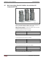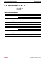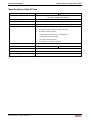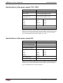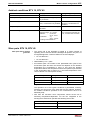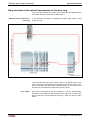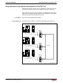
1
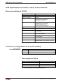
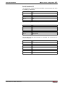
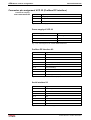
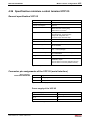
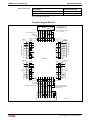
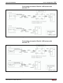
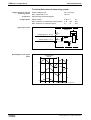
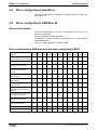
II Contents
Rexroth SYNAX 200
Option Cards for the PLC ........................................................................................................ 4-8
4.5
Brief description RECO02: local I/O components ........................................................................ 4-9
4.6
Brief description Rexroth Inline: decentralized I/O components................................................. 4-10
4.7
Brief description Rexroth Fieldline: decentralized I/O components IP 65 .................................. 4-12
4.8
Brief description PC based visualization units............................................................................ 4-13
4.9
Brief description Windows CE based visualization units VEP.................................................... 4-15
4.10 Brief description miniature control terminal VCP ........................................................................ 4-16
4.11 Installation instructions RECO control ........................................................................................ 4-17
Installing the module carriers................................................................................................. 4-17
Arrangement of the module carrier........................................................................................ 4-17
Installing the modules ............................................................................................................ 4-18
Grounding .............................................................................................................................. 4-19
4.12 Slot addressing of the module carriers ....................................................................................... 4-20
4.13 Combination options module carrier - PPC - I/O modules ......................................................... 4-21
Motion control configuration .................................................................................................. 4-21
4.14 Installation instructions PPC-P control ....................................................................................... 4-22
4.15 Combination possibilities visualization units BTV - PPC-P ........................................................ 4-23
4.16 Specifications PPC-R2x.............................................................................................................. 4-24
General specifications PPC-R2x ........................................................................................... 4-24
Power supply PPC-R2x ......................................................................................................... 4-24
I/O Bus supply by control....................................................................................................... 4-24
Digital inputs and outputs of the PPC-R2x ............................................................................ 4-25
EMC of the PPC-R2x............................................................................................................. 4-25
DERATING I/O bus supply .................................................................................................... 4-25
Interfaces of the PPC-R2x..................................................................................................... 4-25
Connecting the power supply of the PPC-R2x ...................................................................... 4-26
Connector pin assignments of the PPC-R2x......................................................................... 4-26
4.17 Specifications PPC-P11.............................................................................................................. 4-28
General specifications PPC-P ............................................................................................... 4-28
Power supply PPC-P ............................................................................................................. 4-28
Digital inputs and outputs of the PPC-P ................................................................................ 4-28
Interfaces of the PPC-P......................................................................................................... 4-28
Connector pin assignment of the PPC-P............................................................................... 4-29
4.18 Procedure at HMI components ................................................................................................... 4-30
General information ............................................................................................................... 4-30
Software for compact devices (VCP)..................................................................................... 4-30
Software for Windows CE based devices and PC based devices ........................................ 4-31
4.19 Specifications BTV 16, BTV 40 .................................................................................................. 4-32
Specifications of the front ...................................................................................................... 4-32
Specifications of the PC box.................................................................................................. 4-33
Specifications of the power supply 115V / 230V ................................................................... 4-34
Specifications of the power supply 24V................................................................................. 4-34
Ambient conditions BTV 16, BTV 40 ..................................................................................... 4-35
Wear parts BTV 16, BTV 40 .................................................................................................. 4-35
4.20 Specifications VSP 16, VSP 40 .................................................................................................. 4-36
Specifications of the front ...................................................................................................... 4-36
DOK-SYNAX*-SY*-12VRS**-PR01-EN-P