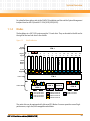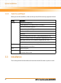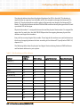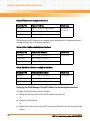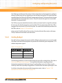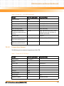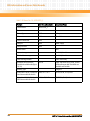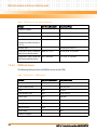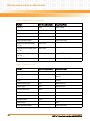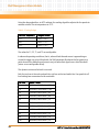
1
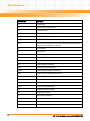
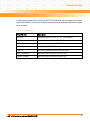
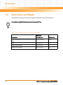
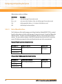
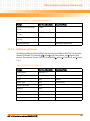
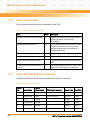
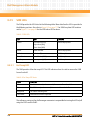
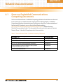
Configuring and Operating the System
The FTMs have variable speed fan control, which is dependent on the temperature readings in
the shelf. Airflow rates can vary depending on the fan speed and payload. Fan speed levels are
controlled from the SAM via the IPM shelf management software. The fan speed levels change
automatically based on temperature sensors. If any FRU exceeds the upper non-recoverable
threshold, it is powered down.
The FTM has an ejector handle that interfaces with a mechanical switch to signal the software
for hot swap. The handle and captive screws lock the FTM securely into the shelf. Each FTM is
equipped with three status LEDs on the face plate. For removal and installation procedures for
the FTMs, refer to Chapter 4, FRU Installation.
In the event of a Fan/Filter Out-of-Service alarm, first check the fan filters (only on the lower
FTMs) to make sure the airflow is not obstructed.
5.6.2
Cooling Budget
The shelf cooling is designed to operate with the following temperature rises across the shelf.
This allows cards with these dissipations to operate with commercial grade components, 70°C
ambient temperature typical.
Table 5-5 Cooling Budget
Ambient Temperature
Temperature Rise
25°C
Delta T = 20° C
40°C
Delta T = 15° C
55°C
Delta T = 10° C
The following guidelines can assist in determining the cause of the cooling failure. Also refer to
Environmental Requirements on page 37 for important information regarding ambient
temperature requirements during servicing. If a cooling failure occurs, the failure may be
caused by a failed fan or possibly a clogged filter. Check the filter first before replacing the FTM.
For further information of nonrecoverable temperature events, refer to Chapter 7, FRU
Information and Sensor Data Records, on page 123.
AXP 1410 Installation and Use (6806800H70D)
105