1
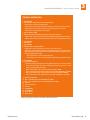
technical information / troubleshooting
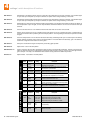
Condition
Actuator(s) will not
run. Power LED
is OFF.
Possible Solution
•
•
Check that power to the operator is turned ON.
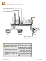
Check for 24 VAC at terminals 19 and 20. If voltage measures OK,
check the terminal strip or replace the circuit board.
•
Momentarily jumper terminal 1 to terminal 2. If the input LED does
not come ON, check the terminal strip or replace the circuit board. If
LED does come ON, proceed to next steps.
Check the fuses.
•
•
Actuator(s) will
not run. Power
LED is ON.
•
Gate opens a
short distance,
then stops and
reverses.
•
•
•
•
•
•
Gate opens but
will not close.
•
•
•
•
•
Gate closes but
will not open.
•
•
Gate starts
to close, then
reverses to open.
•
•
Remove the circuit board. With two 14 AWG insulated jumper wires,
momentarily jumper the battery terminals to the motor terminals (1,
2) of the Primary actuator connector. The actuator should run. Swap
the two wires at the terminal strip. The actuator should run in the
opposite direction. Repeat these steps using the Secondary actuator
connector.
If the actuator(s) run in both directions in the step above, replace
the control board. If the actuator(s) do not run, or run in only one
direction, problem can be a bad actuator, wire connections from the
control board to the actuator(s) or a bad control board.
Disconnect the gate from the actuator and check that the gate swings
freely without any binding.
Check the reverse sensitivity.
Check the secondary safety devices.
Replace the circuit board.
Check the input LED’s. Any ON will hold the gate open and indicates
a problem with a keying device.
Check the secondary safety devices. Any activated will hold the gate
open and indicates a problem with the safety device.
Check the loop detectors. Any activated can hold the gate open and
indicates a problem with the loop detector or ground loop.
Operator may be in a “soft shutdown.” Activate any keying device to
determine if operator returns to normal operation.
If automatic close is desired, be sure SW1, switch 4 is ON.
Operator may be in a “soft shutdown.” Check input LED’s. If any are
ON, momentarily disconnect, then re-connect the wire going to the
input terminal. Actuator should open.
Check to be sure that the actuator is running in the proper direction.
Turn power OFF, disconnect batteries and solar panels, and then
back ON. Activate a keying device. Actuator should run in the open
direction. If actuator runs in the close direction, turn power OFF
and change direction switch SW1, switches 1 and/or 2. Re-test and
reconnect batteries and solar panels.
Be sure that the respective LED on the control board lights when the
keying device connected to the respective terminal is activated. If
LED does not light, momentarily place a jumper wire from terminal
1 to the input terminal being checked. If LED lights and gate opens,
problem is with the keying device. If LED does not light, replace
control board.
Disconnect the gate from the actuator and check that the gate
operates freely without any binding.
Check the loop detector LED’s and input LED’s. Any that flash ON
will cause the gate to reverse.
If a shadow loop is used, check for proper wiring. A mis-wired
shadow loop detector will cause the gate to reverse.
•
Replace the circuit board.
Gate closes and
then re-opens.
•
•
Check for any input or loop detector LED’s that are ON.
Check that the operator is running in the proper direction (see “gate
closes but will not open” above).
Alarm sounds for
5 minutes and
then beeps once
every 5 seconds.
Operator will not
run.
•
Operator is in a “hard shutdown” condition. Reset switch must be
activated to return operator to normal operation.
6400-065-E-05-07
5
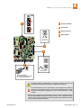
Have the following diagnostic
tools available: VOM meter with
minimum voltage memory or
min-max range to check voltage
and continuity. Meg-ohm meter
capable of checking up to 500 megohms of resistance to properly
check ground loop integrity. A
malfunction can be isolated to one
of the following:
•
•
•
Gate Operator
Loop System
Keying Devices.
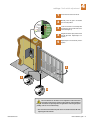
Disconnect all external inputs to
the circuit board.
1. Check the input indicator LED’s.
They should only come ON when
a keying device (card reader,
push button, etc.) is activated.
If any of the input LED’s are ON
continuously, this will cause
the gate operator to hold open.
Disconnect the keying devices
one at a time until the LED
goes OFF (see troubleshooting
guide).
2. If the operator stops or holds
open, check external secondary
entrapment protection devices
for any shorts or malfunction.
3. A malfunction in a loop or
loop detector can cause the
gate operator to hold open, or
not detect a vehicle when it is
present over the loop. Pull the
loop detector circuit boards from
the loop ports on the operator
circuit board. If the malfunction
persists, the problem is not
with the loop system. For more
information refer to the loop
detector instruction sheet and
the DoorKing Loop and Loop
Detector Information Manual.
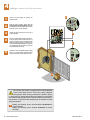
4. Check that there are no shorted
or open control wires from
the keying devices to the gate
operator. If a keying device fails
to open the gate, momentarily
jumper across terminals 1 and 2
on the control board. If the gate
operator starts, this indicates
that a problem exist with the
keying device and not with the
gate operator.
5. Check the supply voltage and
batteries. A voltage drop on the
supply line (usually caused by
using too small supply voltage
wires) will cause the operator to
malfunction. Batteries should
be fully charged for proper
operation, replace batteries
every two years on average.
6400 installation guide
25