1
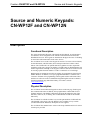
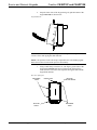
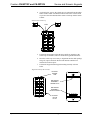
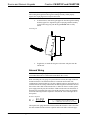
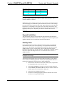
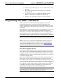
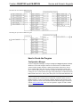
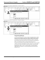
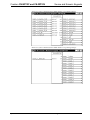
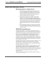
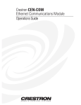
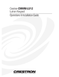
Crestron CN-WP12F and CN-WP12N Source and Numeric Keypads Contents Source and Numeric Keypads: CN-WP12F and CN-WP12N Description Functional Description Physical Description Leading Specifications Setup Custom Switch Cap Installation Network Wiring Keypad Installation Identity Code Programming with SIMPL™ Windows How the Program Works How to Create the Program Problem Solving Troubleshooting Further Inquiries Return and Warranty Policies Merchandise Returns / Repair Service CRESTRON Limited Warranty Operations Guide - DOC. 5788A 1 1 1 1 3 3 3 6 7 7 8 8 9 12 12 12 13 13 13 Contents • i Crestron CN-WP12F and CN-WP12N Source and Numeric Keypads Source and Numeric Keypads: CN-WP12F and CN-WP12N Description Functional Description The Source and Numeric Keypads, CN-WP12F and CN-WP12N, are wall-mounted user-interface devices designed to work with the CNX-PAD8 Professional Audio Distribution Processor. The keypads are installed into the physical rooms of a building to control the CNX-PAD8 and its audio source devices. The CN-WP12F serves as the source keypad. It consists of six source selector buttons, an ON/OFF button, a MUTE button, device transport control and volume control buttons. The CN-WP12N is an optional numeric keypad that is used to expand the capabilities of the source keypad. It contains a CLEAR button, an ENTER button, and numeric digit buttons 0 through 9. The keypad is ideal for audio device functions such as selecting a particular track number of a CD or a certain disc of a CD changer. Both keypads are standard Cresnet devices and may be programmed as desired using SIMPL Windows. In addition, a set of pre-programmed modules is available from Crestron to facilitate easier programming of the keypads and the CNX-PAD8. These modules are referred to as the CrestronHome Programming Kit and can be obtained from the Downloads page (MACROS Library) of Crestron’s website (www.crestron.com). Physical Description The CN-WP12F and CN-WP12N keypads are shown on the next page. Each keypad has 12 buttons and on the CN-WP12F, the top eight buttons contain LEDs for user feedback indicators. The SIMPL™ Windows program determines the state of the indicators, either off, on, or flashing. The CN-WP12N has an LED for the ENTER button only. The CN-WP12F is available in either ivory or white (part numbers CN-WP12FI and CN-WP12FW, respectively). The CN-WP12N is also available in ivory or white (CN-WP12NI and CN-WP12NW). Wall-plates are not supplied. The CN-WP12F has standard source selector switch caps installed and a kit of custom switch caps is provided. Operations Guide - DOC. 5788A Source and Numeric Keypads: CN-WP12F and CN-WP12N • 1 Source and Numeric Keypads Crestron CN-WP12F and CN-WP12N CN-WP12F and CN-WP12N Source and Numeric Keypads CN-WP12F SOURCE SELECTOR BUTTONS WITH LED INDICATORS ON/OFF AND MUTE BUTTONS WITH LED INDICATORS CD FM CD 2 DSS TAPE AUX ON/OFF MUTE 4.10 in (10.41 cm) (SIDE VIEW OF BOTH CN-WP12F AND CN-WP12N) VOL VOL TRANSPORT CONTROL AND VOLUME BUTTONS (WITHOUT LEDs) KEYPAD KEYPAD MOUNTING ASSEMBLY NETWORK WIRING CONNECTOR 1.74 in (4.42 cm) CN-WP12N CLEAR BUTTON (WITHOUT LED) AND ENTER BUTTON WITH LED INDICATOR CLEAR NUMERIC DIGITS 0 THROUGH 9 BUTTONS (WITHOUT LEDs) 1.55 in (3.94 cm) ENTER 1 2 3 4 5 6 7 8 9 0 1.90 in (4.83 cm) 4.10 in (10.41 cm) 1.74 in (4.42 cm) CN-WP12F Custom Switch Cap Kit DSS 2 TUNER SAT 2 DVD AM (NOT DRAWN TO SCALE) SAT TV FM 2 AUX AUX 2 • Source and Numeric Keypads: CN-WP12F and CN-WP12N Operations Guide - DOC. 5788A Crestron CN-WP12F and CN-WP12N Source and Numeric Keypads Leading Specifications The table below provides a summary of leading specifications for the CN-WP12F and CN-WP12N. Dimensions and weight are rounded to the nearest hundredth unit. Leading Specifications of the CN-WP12F and CN-WP12N SPECIFICATION SIMPL Windows CNX Upgrade File CNHome.zip Dimensions & Weight DETAILS 1 Power Requirements Default Network IDs 1 24 VDC, Load Factor of 2 Watts 4C for the CN-WP12F and 48 for the CN-WP12N 2 Version 1.30.01 or later with library update file smwlib45.exe and library 2 update document smwlib45.txt or later. 3 Version 5.04.11x.upz or later 2 Version 1.0. or later Height: 4.10 in (10.41 cm) W idth: 1.74 in (4.42 cm) Depth: 1.90 in (4.83 cm) Weight: 5.50 oz (.16 kg) 1 The listed details apply to the CN-WP12F or the CN-WP12N as individual units not as a pair or set. 2 The latest software versions can be obtained from the Downloads page (SIMPLWIN and MACROS Libraries) of Crestron’s website (www.crestron.com). New users are required to register in order to obtain access to the FTP site. 3 Filenames for CNX upgrade files have a UPZ extension and can be obtained from the Downloads As of the date of manufacture, these units have been tested and found to comply with specifications for CE marking. NOTE: These devices comply with part 15 of the FCC rules. Operation is subject to the following two conditions: (1) these devices may not cause harmful interference, and (2) these devices must accept any interference received, including interference that may cause undesired operation. Setup Custom Switch Cap Installation On the CN-WP12F, the top six buttons serve the function of source selector buttons. The keypad has standard source selector switch caps installed and a kit of custom switch caps is also supplied. The following procedure describes how to install the custom switch caps (or re-arrange the standard switch caps) onto the keypad: 1. Operations Guide - DOC. 5788A If applicable, remove the designer or decorator wall-plate from the CN-WP12F. Source and Numeric Keypads: CN-WP12F and CN-WP12N • 3 Source and Numeric Keypads 2. Crestron CN-WP12F and CN-WP12N Grasp the lower-sides of the keypad and gently pull the bottom of the keypad outwards as shown below. Keypad Removal CAUTION: To avoid damage to the keypad shell during the next step, do not use excessive force when prying the shell outwards. NOTE: The position of each switch cap is important to the CNX-PAD8 program. Notice the location of each switch cap before disassembly. 3. Using a small flat-tip screwdriver or your fingers, pry the sides of the keypad shell outwards until the four retainer tabs (shown below) recede from the sides of the shell. Separate the keypad shell from the keypad PCB and base. Rear View of Keypad RETAINER TABS UPPER-TAB KEYPAD SHELL 4 • Source and Numeric Keypads: CN-WP12F and CN-WP12N KEYPAD PCB AND BASE RETAINER TABS Operations Guide - DOC. 5788A Crestron CN-WP12F and CN-WP12N 4. Source and Numeric Keypads As shown below, remove the switch cap to be replaced from the rubber button actuator. Make sure that the indicator lens of the custom switch cap is above the LED and install the custom switch cap onto the button actuator. Install Custom Switch Cap CD DSS 2 LED FM CD 2 DSS TAPE AUX ON/OFF MUTE VOL VOL 5. Position the keypad shell so that the upper-tab faces upwards (as the switch caps are readable) and lower it onto the keypad PCB and base. 6. Move the switch caps as necessary to align them into the shell openings and gently squeeze the shell onto the PCB and base until the four retainer tabs click into place. 7. Position the keypad and the keypad mounting assembly as shown below. Alignment Points for Re-assembly KEYPAD UPPERTAB DSS 2 FM CD 2 DSS TAPE AUX ON/OFF MUTE VOL MOUNTING ASSEMBLY UPPER-SLOT MOUNTING ASSEMBLY 18-PIN SOCKET VOL KEYPAD 18-PIN PLUG Operations Guide - DOC. 5788A Source and Numeric Keypads: CN-WP12F and CN-WP12N • 5 Source and Numeric Keypads Crestron CN-WP12F and CN-WP12N CAUTION: To avoid damage to the pins of the plug, do not use excessive force when seating the keypad into the keypad mounting assembly. When properly aligned, the 18-pin plug inserts easily into the socket 8. As shown below, insert the keypad upper-tab into the keypad mounting assembly upper-slot. Align the keypad 18-pin plug with the assembly 18-pin socket and gently push the keypad inward until it is fully seated. Install Keypad 9. If applicable, re-install the designer or decorator wall-plate onto the CN-WP12F. Network Wiring NOTE: When making category 5 wire connections, refer to the latest revision of the Cresnet Mini Network Cat 5 Interconnect Data Sheet (Doc. 5819). When calculating the wire gauge for a particular network run, the length of the run and the load factor of each network unit to be connected must be taken into consideration. If network units are to be daisy-chained on the run, the load factor of each network unit to be daisy-chained must be added together to determine the load factor of the entire chain. If the network unit is a home-run from a Crestron system power supply network port, the load factor of that network unit is the load factor of the entire run. The length of the run in feet and the load factor of the run should be used in the following resistance equation to calculate the value on the right side of the equation. Resistance Equation R < 4 0 ,000 L x LF Where: R = Resistance (refer to next table). L = Length of run (or chain) in feet. LF = Load factor of entire run (or chain). The required wire gauge should be chosen such that the resistance value is less than the value calculated in the resistance equation. Refer to the table on the next page: 6 • Source and Numeric Keypads: CN-WP12F and CN-WP12N Operations Guide - DOC. 5788A Crestron CN-WP12F and CN-WP12N Source and Numeric Keypads Wire Gauge Values RESISTANCE (R) W IRE GAUGE 4 6 10 15 16 18 20 22 NOTE: All network wiring must consist of two twisted-pairs. One twisted pair is the +24V conductor and the GND conductor and the other twisted pair is the Y conductor and the Z conductor. NOTE: When daisy-chaining network units, always twist the ends of the incoming wire and outgoing wire which share a pin on the network connector. After twisting the ends, tin the twisted connection with solder. Apply solder only to the ends of the twisted wires. Avoid tinning too far up the wires or the end becomes brittle. After tinning the twisted ends, insert the tinned connection into the network connector and tighten the retaining screw. Repeat the procedure for the other three network conductors. Keypad Installation After the network wiring has been installed, the CN-WP12F and CN-WP12N are installed into standard electrical switch boxes. Designer or decorator wall-plates (not supplied) should be used to complete the mechanical installation. Identity Code Every equipment and user interface within the network requires a unique identity code (NET ID). These codes are recognized by a two-digit hexadecimal number from 03 to FE. The NET ID of the keypad must match an ID code specified in the SIMPL Windows program. The NET IDs of the CN-WP12F and CN-WP12N keypads are factory set to 4C and 48, respectively. The NET IDs of multiple keypads must all be unique and changed from a PC via VisionTools™ Pro (VT Pro) or SIMPL Windows. NOTE: VT Pro is a Windows compatible software package for creating Crestron touchpanel screen designs. The method for changing the unit’s NET ID is identical regardless of the software chosen. Attach one of the keypads to the control system (verify that the software is running) and complete the following steps to change the NET ID. Operations Guide - DOC. 5788A 1. Disconnect all network devices from the control system, except for the one keypad that needs to have its NET ID set. 2. Select Tools | Viewport to open the “Crestron Viewport” dialog box. 3. Select Functions | Set Network ID. The software checks the baud rate and then opens the “Set Network ID” dialog box. 4. In the dialog box, highlight the keypad. 5. The NET ID of the keypad appears in the box below the list. Use the scroll arrow to assign another NET ID. Source and Numeric Keypads: CN-WP12F and CN-WP12N • 7 Source and Numeric Keypads Crestron CN-WP12F and CN-WP12N 6. When the assigned NET ID appears, select the Set ID button to initiate the change. 7. The software responds with a successful message to confirm the changed NET ID. 8. To verify this procedure, select Diagnostics | Report Network Devices. Confirm that the keypad has a new NET ID code. 9. Reconnect other network devices that were disconnected in step 1. Programming with SIMPL™ Windows SIMPL (Symbol Intensive Master Programming Language) is an easy-to-use programming language that is completely integrated and compatible with all Crestron system hardware. The objects that are used in SIMPL Windows are called symbols. SIMPL Windows offers drag and drop functionality in a familiar Windows environment. SIMPL Windows is Crestron Electronics' software for programming Crestron control systems. It provides a well-designed graphical environment with a number of workspaces (i.e., windows) in which a programmer can select, configure, program, test, and monitor a Crestron control system. The next two subsections describe a sample SIMPL Windows program that utilizes the CN-WP12F and the CN-WP12N. NOTE: The following descriptions assume that the reader has knowledge of SIMPL Windows. If not, refer to the extensive help information provided with the software. NOTE: There is no need to recreate the sample SIMPL Windows program. The latest CrestronHome Programming Kit CNHOME.ZIP can be obtained from the Downloads page (MACROS Library) of Crestron’s website (www.crestron.com). New users are required to register in order to obtain access to the FTP site. How the Program Works The Source and Numeric Keypads are fully customizable and can be programmed as desired. However, the CrestronHome Programming Kit contains the necessary preprogrammed software to operate the CNX-PAD8 with the keypads. The kit contains the SIMPL Windows program, the operational instruction PDF file, and VT Pro files to customize touchpanel displays. Refer to the block diagrams on the next page. The CN-WP12F provides button press signals (source selector, ON/OFF, MUTE, transport and volume control) to the CrestronHome Control module of the CrestronHome Programming Kit. This module processes the signals according to the program and provides feedback signals that are used to illuminate the LED indicators of the CN-WP12F. The button press signals of the CN-WP12N (CLEAR, ENTER, and numeric digits 0 through 9) are input to the CrestronHome Room Keypad module. This module processes the button press signals and provides feedback for the LED of the ENTER button. NOTE: In the following example, the input signals of the CrestronHome Room Keypad module have been rearranged for clarity. When programming, refer to the signal names and proper inputs of the SIMPL Windows symbol. 8 • Source and Numeric Keypads: CN-WP12F and CN-WP12N Operations Guide - DOC. 5788A Crestron CN-WP12F and CN-WP12N Source and Numeric Keypads Block Diagram of CN-WP12F SIMPL Program Block Diagram of CN-WP12N SIMPL Program How to Create the Program Configuration Manager Use the Configuration Manager workspace (Project | Configure System) in SIMPL Windows to select and configure all the devices that need to be included into the system. For this example, from the Control Systems folder in the Device Library select CNMSX-PRO. Drag and drop the CN-WP12F (Wired Panels folder in the Device Library) into System View. For this example, the NET ID of the CN-WP12F is being set to 4C as shown on the next page. Drag and drop the CN-WP12N (Wired Panels folder in the Device Library) also into System View and set the NET ID to 48. NOTE: SIMPL Windows v1.30.01 or later is required to program the control system containing the CN-WP12F and CN-WP12N. If using an earlier version of SIMPL Windows, Crestron recommends a SIMPL Windows and operating system upgrade. The latest version can be obtained from the Downloads page of Crestron’s website (www.crestron.com). New users are required to register in order to obtain access to the FTP site. Operations Guide - DOC. 5788A Source and Numeric Keypads: CN-WP12F and CN-WP12N • 9 Source and Numeric Keypads Crestron CN-WP12F and CN-WP12N System View of the CN-WP12F in SIMPL Windows’ Configuration Manager System View of the CN-WP12N in SIMPL Windows’ Configuration Manager Programming Manager Use the Programming Manager workspace (Project | Program System) in SIMPL Windows to select symbols and assign their respective signals. For this example, CN-WP12F and CN-WP12N symbols were added automatically when the devices were added to the system in the Configuration Manager workspace. Expand the Network Modules folder and double-click on the CN-WP12F and CN-WP12N for detail views (alternatively CTRL+D or drag and drop into Detail View). The signals shown after this paragraph control the CNX-PAD8 from one room using a single set of keypads. The signals are in reference to Room 1. The CNX-PAD8 may contain up to eight rooms and the assigned signal names should reflect the appropriate room, room_1_source_1, room_2_source_1, etc. Daisy-chained CNX-PAD8s may contain up to 32 rooms and all signal names must reflect the appropriate room. 10 • Source and Numeric Keypads: CN-WP12F and CN-WP12N Operations Guide - DOC. 5788A Crestron CN-WP12F and CN-WP12N Source and Numeric Keypads Detail View of the CN-WP12F Symbol in SIMPL Windows’ Programming Manager Detail View of the CN-WP12N Symbol in SIMPL Windows’ Programming Manager Operations Guide - DOC. 5788A Source and Numeric Keypads: CN-WP12F and CN-WP12N • 11 Source and Numeric Keypads Crestron CN-WP12F and CN-WP12N Problem Solving Troubleshooting The table below provides corrective action for possible trouble situations. If further assistance is required, please contact a Crestron technical support representative. CN-WP12F and CN-WP12N Troubleshooting TROUBLE Keypad does not function when a button is depressed. Keypad functions but LED indicator does not illuminate. POSSIBLE CAUSE(S) Keypad is not receiving network power. Keypad NET ID is not unique. Keypad NET ID is not set to match the NET ID of the SIMPL Windows program. Feedback signal names incorrect in SIMPL Windows program. CORRECTIVE ACTION Check wiring network wiring connector and confirm that power is supplied to the unit. From the Viewport (in SIMPL Windows or VT Pro), poll the network (F4) to verify the NET ID. Verify SIMPL Windows program for feedback signal names. Further Inquiries If after reviewing this Operations Guide, you cannot locate specific information or have questions, please take advantage of Crestron's award winning technical support team by calling: • In the US and Canada, call Crestron’s corporate headquarters at 1-888-CRESTRON [1-888-273-7876] or 1-201-767-3400. • In Europe, call Crestron International at +32-15-50-99-50. • In Asia, call Crestron Asia at +852-2341-016. • In Latin America, call Crestron Latin America at +525-574-15-90. For local support from exclusive Crestron factory-trained personnel call: • In Australia, call Soundcorp at +613-941-61066. • In New Zealand, call Amber Technologies at +649-410-8382. 12 • Source and Numeric Keypads: CN-WP12F and CN-WP12N Operations Guide - DOC. 5788A Crestron CN-WP12F and CN-WP12N Source and Numeric Keypads Return and Warranty Policies Merchandise Returns / Repair Service 1. No merchandise may be returned for credit, exchange, or service without prior authorization from CRESTRON. To obtain warranty service for CRESTRON products, contact the factory and request an RMA (Return Merchandise Authorization) number. Enclose a note specifying the nature of the problem, name and phone number of contact person, RMA number, and return address. 2. Products may be returned for credit, exchange, or service with a CRESTRON Return Merchandise Authorization (RMA) number. Authorized returns must be shipped freight prepaid to CRESTRON, Cresskill, N.J., or its authorized subsidiaries, with RMA number clearly marked on the outside of all cartons. Shipments arriving freight collect or without an RMA number shall be subject to refusal. CRESTRON reserves the right in its sole and absolute discretion to charge a 15% restocking fee, plus shipping costs, on any products returned with an RMA. 3. Return freight charges following repair of items under warranty shall be paid by CRESTRON, shipping by standard ground carrier. In the event repairs are found to be non-warranty, return freight costs shall be paid by the purchaser. CRESTRON Limited Warranty CRESTRON ELECTRONICS, Inc. warrants its Cresnet products, denoted by a "CN" prefix model number, to be free from manufacturing defects in materials and workmanship for a period of three (3) years from the date of shipment to purchaser. Disk drives and any other moving or rotating mechanical parts are covered for a period of one (1) year. CRESTRON warrants all its other products for a period of one year from the defects mentioned above, excluding touchscreen display components which are covered for 90 days. Incandescent lamps are completely excluded from Crestron's Limited Warranty. CRESTRON shall, at its option, repair or replace any product found defective without charge for parts or labor. Repaired or replaced equipment and parts supplied under this warranty shall be covered only by the unexpired portion of the warranty. CRESTRON shall not be liable to honor warranty terms if the product has been used in any application other than that for which it was intended, or if it has been subjected to misuse, accidental damage, modification, or improper installation procedures. Furthermore, this warranty does not cover any product that has had the serial number altered, defaced, or removed. This warranty shall be the sole and exclusive remedy to the purchaser. In no event shall CRESTRON be liable for incidental or consequential damages of any kind (property or economic damages inclusive) arising from the sale or use of this equipment. CRESTRON makes no other warranties nor authorizes any other party to offer any warranty, expressed or implied, including warranties of merchantability for this product. This warranty statement supersedes all previous warranties. Trademark Information All brand names, product names, and trademarks are the sole property of their respective owners. Windows is a registered trademark of Microsoft Corporation. Windows95, Windows98 and WindowsNT are trademarks of Microsoft Corporation. Operations Guide - DOC. 5788A Source and Numeric Keypads: CN-WP12F and CN-WP12N • 13