1
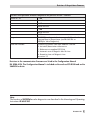
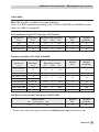
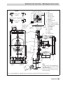
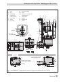
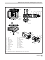
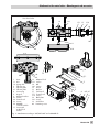
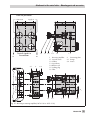
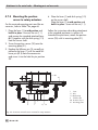
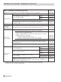
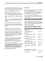
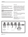
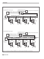
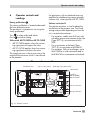
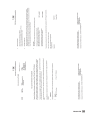
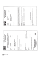
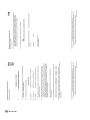
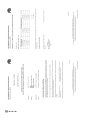
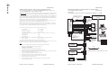
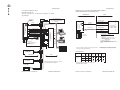
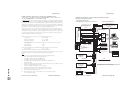
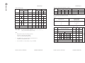
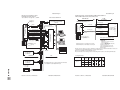
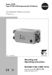
Addendum Page 7
Installation Manual for apparatus approved by FM for use in hazardous locations.
TM
Communication is optionally either according to the FOUNDATION
Fieldbus Specification or
according to PROFIBUS PA in compliance FISCO-Concept
The FISCO Concept allows interconnection of intrinsically safe apparatus to associated apparatus not specifically examined in
such combination. The criteria for interconnection is that the voltage (Vmax/Ui) the current (Imax/Ii) and the power (Pi) which
Addendum Page 8
Intrinsically safe if installed as specified in manufacturer’s installation manual.
FM- approved for hazardous locations
Class I, Zone 0 AEx ia IIC T6:
Class I, II, III Div. 1, Groups A, B, C, D, E, F + G.
Field enclosure NEMA 4X
intrinsically safe apparatus can receive and remain intrinsically safe, considering faults, must be equal or greater than the voltage
(V0C/U0) the current (ISC/I0) and the power (P0) levels which can be delivered by the associated apparatus, considering faults
Serial interface, for connection
to FM approved intrinsically
safe circuit
and applicable factors. In addition, the maximum unprotected capacitance (Ci) and inductance (Li) of each apparatus (other than
FM-approved associated
apparatus suitable
for Profibus PA or FOUNDATION FF
FIELDBUS
the termination) connected to the fieldbus must be less than or equal to 5 nF and 10 µH respectively.
In each segment only one active device, normally the associated apparatus, is allowed to provide the necessary energy for the
other equipment connected to the bus cable has to be passive, meaning that they are not allowed to provide energy to the system,
except to a leakage current of 50mA for each connected device. Separately powered equipment needs a galvanic isolation to
assure that the intrinsically safe fieldbus circuit remains passive.
The cable used to interconnect the devices need to have the parameters in the following range:
Loop resistance R‘:
15 ... 150 Ohm/km
Inductance per unit length L‘:
0,4 ... 1 mH/km
Capacitance per unit length C‘:
80 ... 200
11+
.
12-
Model 3730-43/3730-53
Positioners
fieldbus system The allowed voltage (V0C /Uo) of the associated apparatus is limited to the range of 14V DC. to 24V DC. All
41+
≤ 30 m
Length of trunk cable:
≤ 1 km
Limit switch circuit 2
42-
82-
circuit 3
87+ Binary contact 1
88-
nF/km
circuit 4
85+
86Binary contact 2
circuit 5
Terminal No.
At each end of the trunk cable an approved infallible line termination with the following parameters is suitable:
R = 90 ... 100 Ohm
Isolating amplifier 1 or 2
Channels FM-approved
circuit 1
81+ Forced venting function
C‘ = C‘ line/line + 0,5 C‘ line/screen, if both lines are floating or, C‘ = C‘ line/line + C’line/screen, if the screen is
connected to one line
Length of spur cable:
Fieldbus
External position sensor
(optionally)
supply barrier
evaluation barrier
supply barrier
C = 0 ... 2,2 µF
One of the allowed terminations might already be integrated in the associated apparatus.
evaluation barrier
The number of passive devices connected to the bus segment is not limited due to I.S. reasons. If the above rules are respected,
the inductance and capacitance of the cable will not impair the intrinsic safety of the installation.
I.S.Ground
FM-approved barrier
Notes:
1.
Approved associated apparatus must be installed in accordance with manufacturer instructions
2.
Approved associated apparatus must meet the following requirements:
FM-approved
intrinsically safe
apparatus suitable
for FIELDBUS
Uo or Voc ≤ Ui or Vmax, Io or Isc ≤ Ii or Imax, Po ≤ Pi or Pmax
3.
The maximum non-hazardous area voltage must not exceed 250 V.
4.
The installation must be in accordance with the National Electrical Code ANSI/NFPA 70 and
Hazardous
Safe
Location
Location
ANSI/ISA RP 12.06.01
5.
Each set of wires must be provided with grounded shield. The shield must extend as close to the terminal(s) as possible
and it must be grounded shield at I. S. Barrier ground.
6.
Caution: Use only supply wires suitable for 5 °C above surrounding.
7.
EB 8384-4 EN
8.
Warning: Substitution of components may impair intrinsic safety. PE = I. S. Ground
The polarity for connecting 11 and 12 is of no importance due to an internal rectifier.
9.
FISCO concept applies to fieldbus / circuit only.
10.
Entity parameters apply to circuit 2, 3 and 4 and further required to meet the following conditions:
FM-approved
intrinsically safe
apparatus suitable
for FIELDBUS
The installation must be in accordance with the National Electrical
Code ANSI/NFPA 70 and ANSI/ISA RP 12.06.01
FM-approved
termination with
R = 90 . . .100Ω,
C = 0 . . .2,2µF
Co ≥ Ci + Ccable; Lo ≥ Li + Lcable
Revisions Control No. 1: March.2006
Addendum to EB 8384-5 EN
Revisions Control No. 1: March.2006
Addendum to EB 8384-5 EN
119