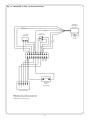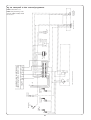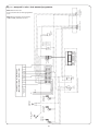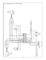
1
3. The terminal must not cause an obstruction nor the discharge
cause a nuisance as a result of either flue gases or terminal noise.
4. If the terminal is fitted within 600mm of a plastic/painted gutter or painted eaves then an aluminium or stainless steel shield
at least 750mm long should be fitted to protect the surface.
5. If a terminal is fitted less than 2 metres above a surface to
which people have access a terminal guard should be fitted. A
flue terminal guard kit is available from Worcester, Bosch Group,
Part Number 7 716 190 017.
6. When fitting the flue terminal guard refer to the instructions
supplied with the flue terminal guard kit.
7. Flue System
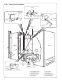
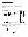
7.1 The appliance is supplied with a telescopic flue system that
caters for 102mm (4 inch) to 460mm (18 inch) Wall thickness.
For details of the installation procedure refer to Section 11.6. of
these installation and servicing instructions.
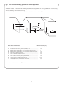
7.2 Siting the flue outlet terminal
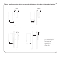
1. The flue outlet terminal must be located in a suitable position,
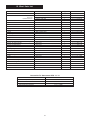
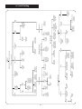
as shown in fig.8, such that the products of combustion can be
freely dispersed without the possibility of the gases entering the
dwelling or that of a neighbouring dwelling. The flue outlet can
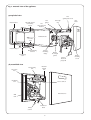
be seen in figs. 6 and 7.
2. Discharge of flue gases into car ports or narrow passageways
is not recommended.
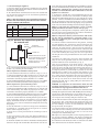
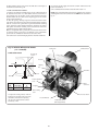
5mm Minimum
Fig. 6. Flue installation
96
442
131
104
49
65
104
Flue
terminal
guard
(optional
extra)
A
328
417
442
A
FRONT VIEW
B
See fig. 8 for flue outlet
terminating positions.
Fig. 7. Flue location
A Flue outlet
B Wall trim
C External cover
C
C
NOTE: Ensure a minimum gap of 5mm between the external
cover and wall trim to allow sufficient air for combustion.
Locating tabs
External duct
Locating slot
Flue locating tab
Flue
outlet
Flue locking screw
NOTE: The Splash plate/seal
should be hard up against
the External Cover.
SIDE
VIEW
Splash plate
Seal
External Cover
8