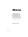
1
AT-MCF6ST, SC AT-MCF6VF, SM AT-MCF12ST, SC AT-MCF12VF, SM Multichannel Ethernet Media Converters Installation Guide PN 613-10830-00 Rev B Copyright 2000 Allied Telesyn International, Corp. 960 Stewart Drive Suite B, Sunnyvale CA USA 94086 All rights reserved. No part of this publication may be reproduced without prior written permission from Allied Telesyn International, Corp. Ethernet is a registered trademark of Xerox Corporation. All other product names, company names, logos or other designations mentioned herein are trademarks or registered trademarks of their respective owners. Allied Telesyn International, Corp. reserves the right to make changes in specifications and other information contained in this document without prior written notice. The information provided herein is subject to change without notice. In no event shall Allied Telesyn International, Corp. be liable for any incidental, special, indirect, or consequential damages whatsoever, including but not limited to lost profits, arising out of or related to this manual or the information contained herein, even if Allied Telesyn International, Corp. has been advised of, known, or should have known, the possibility of such damages. Safety Warnings Standards: This product meets the following standards U.S. Federal Communications Commission RADIATED ENERGY Note: This equipment has been tested and found to comply with the limits for a Class A digital device pursuant to Part 15 of FCC Rules. These limits are designed to provide reasonable protection against harmful interference when the equipment is operated in a commercial environment. This equipment generates, uses, and can radiate radio frequency energy and, if not installed and used in accordance with this instruction manual, may cause harmful interference to radio communications. Operation of this equipment in a residential area is likely to cause harmful interference in which case the user will be required to correct the interference at his own expense. Note: Modifications or changes not expressly approved of by the manufacturer or the FCC, can void your right to operate this equipment. Industry Canada This Class A digital apparatus meets all requirements of the Canadian InterferenceCausing Equipment Regulations. Cet appareil numérique de la classe A respecte toutes les exigences du Règlement sur le matériel brouilleur du Canada. RFI Emission EN55022 Class A ! 1 WARNING: In a domestic environment this product may cause radio interference in which case the user may be required to take adequate measures. ! 2 Immunity EN50082-1 ! 3 Electrical Safety EN60950, UL1950, CSA 950 ! 4 Laser EN60825 ! 5 Important: Appendix A contains translated safety statements for installing this equipment. When you see the !, go to Appendix A for the translated safety statement in your language. Wichtig: Anhang A enthält übersetzte Sicherheitshinweise für die Installation dieses Geräts. Wenn Sie ! sehen, schlagen Sie in Anhang A den übersetzten Sicherheitshinweis in Ihrer Sprache nach. Vigtigt: Tillæg A indeholder oversatte sikkerhedsadvarsler, der vedrører installation af dette udstyr. Når De ser symbolet !, skal De slå op i tillæg A og finde de oversatte sikkerhedsadvarsler i Deres eget sprog. Belangrijk: Appendix A bevat vertaalde veiligheidsopmerkingen voor het installeren van deze apparatuur. Wanneer u de ! ziet, raadpleeg Appendix A voor vertaalde veiligheidsinstructies in uw taal. Important: L'annexe A contient les instructions de sécurité relatives à l'installation de cet équipement. Lorsque vous voyez le symbole !, reportez-vous à l'annexe A pour consulter la traduction de ces instructions dans votre langue. Tärkeää: Liite A sisältää tämän laitteen asentamiseen liittyvät käännetyt turvaohjeet. Kun näe !-symbolin, katso käännettyä turvaohjetta liitteestä A. Importante: l’Appendice A contiene avvisi di sicurezza tradotti per l’installazione di questa apparecchiatura. Il simbolo !, indica di consultare l’Appendice A per l’avviso di sicurezza nella propria lingua. Viktig: Tillegg A inneholder oversatt sikkerhetsinformasjon for installering av dette utstyret. Når du ser !, åpner du til Tillegg A for å finne den oversatte sikkerhetsinformasjonen på ønsket språk. Importante: O Anexo A contém advertências de segurança traduzidas para instalar este equipamento. Quando vir o símbolo !, leia a advertência de segurança traduzida no seu idioma no Anexo A. Importante: El Apéndice A contiene mensajes de seguridad traducidos para la instalación de este equipo. Cuando vea el símbolo !, vaya al Apéndice A para ver el mensaje de seguridad traducido a su idioma. Obs! Bilaga A innehåller översatta säkerhetsmeddelanden avseende installationen av denna utrustning. När du ser !, skall du gå till Bilaga A för att läsa det översatta säkerhetsmeddelandet på ditt språk. iii Table of Contents Safety Warnings ............................................................................................. iii Welcome to Allied Telesyn ......................................................................... vii Where to Find Web-based Guides.................................................................... vii Documentation Conventions ............................................................................ vii Contacting Allied Teleysn ............................................................................... viii For Technical Support and Services........................................................ viii Technical Support E-mail Addresses ......................................................viii FTP Server .................................................................................................. ix For Sales or Corporate Information.................................................................. ix Tell Us What You Think.................................................................................... ix AT-MCF6xx and AT-MCF12xx Multichannel Ethernet Media Converters ........................................................................................... 1 System Models .................................................................................................... 2 Features and Components ................................................................................. 3 Twisted Pair and Fiber Optic Ports............................................................ 4 Port LEDs .................................................................................................... 5 Link Test Switch.......................................................................................... 5 Reset Button ................................................................................................ 6 MissingLink Feature................................................................................... 6 Duplex Mode ................................................................................................ 7 Optional Redundant Power Supply Slot .................................................... 8 Power Inlet................................................................................................... 8 10Base-T, Management, and RS232 Ports................................................. 9 Network Topology ............................................................................................... 9 Installing the Multichannel Media Converter ................................................ 11 Selecting a Site for the Multichannel Media Converter.......................... 11 Planning the Installation .......................................................................... 11 Checking the Multichannel Media Converter Package........................... 13 Reviewing Safety Precautions .................................................................. 14 Installing the Multichannel Media Converter as a Standalone Unit..... 15 Installing the Multichannel Media Converter in a Rack ........................ 17 Verifying the Installation.......................................................................... 19 Operating the Multichannel Media Converter ............................................... 20 v Troubleshooting ................................................................................................ 21 Resetting the Unit ..................................................................................... 22 Technical Specifications ................................................................................... 23 Technical Support and Service ........................................................................ 24 Warranty ........................................................................................................... 24 Appendix A Translated Safety and Emission Information ....................................... 25 Appendix B AT-MCF6xx and MCF12xx Installation Guide Feedback .................... 37 Appendix C Technical Support Fax Order ................................................................... 39 vi Welcome to Allied Telesyn This guide contains instructions on how to install and configure the AT-MCF6xx and AT-MCF12xx Series Multichannel Ethernet Media Converters. Where to Find Web-based Guides The Allied Telesyn web site at www.alliedtelesyn.com provides you with an easy way to access the most recent documentation and technical information for all of our products. For product guides, you can go directly to the following web page: www.alliedtelesyn.com/techhome.htm. Documentation Conventions This guide uses several conventions that you should become familiar with first before you begin to install the product. Note A note provides additional information. Caution A caution indicates that performing or omitting a specific action may result in equipment damage or loss of data. Warning A warning indicates that performing or omitting a specific action may result in bodily injury. vii Contacting Allied Teleysn For Technical Support and Services Americas Germany United States, Canada, Mexico, Central America, South America Tel: 1 (800) 428-4835 Fax: 1 (503) 639-3176 Germany, Switzerland, Austria, Eastern Europe Tel: (+49) 30-435-900-126 Fax: (+49) 30-435-70-650 Asia Singapore, Taiwan, Thailand, Malaysia, Indonesia, Korea, Philippines, China, India, Hong Kong Tel: (+65) 3815-612 Fax: (+65) 3833-830 Australia Australia, New Zealand Tel: 1 (800) 000-880 Fax: (+61) 2-9438-4966 Italy Italy, Spain, Portugal, Greece, Turkey, Israel Tel: (+39) 02-416047 Fax: (+39) 02-419282 Japan Tel: (+81) 3-3443-5640 Fax: (+81) 3-3443-2443 France United Kingdom France, Belgium, Luxembourg, The Netherlands, Middle East, Africa Tel: (+33) 1-60-92-15-25 Fax: (+33) 1-69-28-37-49 United Kingdom, Denmark, Norway, Sweden, Finland, Iceland Tel: (+44) 1-235-442560 Fax: (+44) 1-235-442680 Technical Support E-mail Addresses United States and Canada [email protected] Latin America, Mexico, Puerto Rico, Caribbean, and Virgin Islands [email protected] United Kingdom, Sweden, Norway, Denmark, and Finland [email protected] viii AT-MCF6xx and AT-MCF12xx Installation Guide FTP Server Address: gateway.centre.com [lowercase letters] Login: anonymous [lowercase letters] Password: your e-mail address [requested by the server at login] For Sales or Corporate Information Allied Telesyn International, Corp. Allied Telesyn International, Corp. 19800 North Creek Parkway, Suite 200 Bothell, WA 98011 Tel: 1 (425) 487-8880 Fax: 1 (425) 489-9191 960 Stewart Drive, Suite B Sunnyvale, CA 94086 Tel: 1 (800) 424-4284 (USA and Canada) Fax: 1 (408) 736-0100 Tell Us What You Think If you have any comments or suggestions on how we might improve this or other documents, please fill out the “AT-MCF6xx and MCF12xx Installation Guide Feedback” on page 37 and return the form to us at the address or fax number provided. ix AT-MCF6xx and AT-MCF12xx Multichannel Ethernet Media Converters The Ethernet AT-MCF6xx and the AT-MCF12xx Multichannel Media Converters are designed to extend the reach of your network by converting your twisted pair cabling into fiber optic cabling. These products, which transfer Ethernet data between 10Base-T and 10Base-FL technologies, enable you to quickly and easily interconnect the nodes in your network to distances of 2 kilometers (1.24 miles) to 15 kilometers (9.3 miles), depending on the model. With this product, remote devices and networks, which previously were difficult to interconnect, are easily interconnected to form one integrated network. The ports on the media converters are grouped into pairs, referred to as “channels,” with each pair consisting of a 10Base-T twisted pair port and a 10Base-FL fiber optic port. Each channel functions as an independent media converter. The Ethernet AT-MCF6xx unit features six channels, providing you with six individual media converters, while the AT-MCF12xx unit features twelve channels, giving you twelve individual media converters. The twisted pair ports are designed to operate with Category 3 or better cabling at a speed of 10 Mbps. The fiber optic ports also operate at a speed of 10 Mbps and are available in a variety of connector types. The fiber optic ports support IEEE standard Multimode Fiber (MMF) or Single-Mode Fiber (SMF) cable. The multichannel media converters can be installed either as standalone units, such as on a table, or in a standard 19-inch rack. The units are easy to install and do not require any software configuration or software management. 1 System Models Table 1 lists the available system models. Table 1 Models of the AT-MCF6xx and AT-MCF12xx Multichannel Media Converters Model Number of Media Converter Channels Type of Fiber Optic Connector Type of Fiber Optic Cabling Maximum Distance1 AT-MCF6ST 6 ST Multimode 2 km (1.24 mi) AT-MCF6SC 6 SC Multimode 2 km (1.24 mi) AT-MCF6VF 6 VF-45 Multimode 2 km (1.24 mi) AT-MCF6SM 6 SC Single-mode 15 km (9.3 mi) AT-MCF12ST 12 ST Multimode 2 km (1.24 mi) AT-MCF12SC 12 SC Multimode 2 km (1.24 mi) AT-MCF12VF 12 VF-45 Multimode 2 km (1.24 mi) AT-MCF12SM 12 SC Single-mode 15 km (9.3 mi) 1. The maximum distance may be less depending on the duplex mode of the nodes and the type of fiber optic cabling used with the media converter. 2 AT-MCF6xx and AT-MCF12xx Installation Guide Features and Components This section describes the features and components of the AT-MCF6xx and AT-MCF12xx Multichannel Media Converters. Figure 1 illustrates the front panel of an AT-MCF6xx system. MCF6SC 10Base-TX/FX Media Converter MANAGEMENT 10Base-T Tx Rx Tx Rx Tx Rx Tx Rx Tx Rx Tx Rx LINK TEST NORM T-LNK POWER BCKP LNK REC F-LNK MAIN TEST Active 1 2 3 4 5 RESET 6 Ready STATION OR HUB RS232 Figure 1 Front Panel of the AT-MC6xx Multichannel Media Converter (Model AT-MCF6SC) Figure 2 illustrates the front panel of an AT-MCF12xx system. Tx Rx Tx Rx Tx Rx Tx Rx Tx Rx Tx Rx Tx Rx Tx Rx Tx Rx Tx Rx Tx Rx Tx Rx 1-6 LINK TEST NORM F-LNK MCF12SC TEST T-LNK 1 Active 2 3 4 5 RESET 6 10Base-TX/FX Media Converter MANAGEMENT 10Base-T 7-12 LINK TEST NORM POWER BCKP LNK REC MAIN TEST 7 8 9 10 11 12 RESET Ready STATION OR HUB RS232 Figure 2 Front Panel of the AT-MCF12xx Multichannel Media Converter (Model AT-MCF12SC) 3 Twisted Pair and Fiber Optic Ports The twisted pair and fiber optic ports on the unit are paired together (see Figure 3). Each pair is referred to as a “channel” and each channel functions as an independent media converter. The AT-MCF6xx Multichannel Media Converter has six channels while the AT-MCF12xx Multichannel Media Converter has twelve channels. Tx Rx 2 Tx Rx Tx Rx Tx Rx Tx Rx Tx Rx Tx Rx Tx Rx 1-6 LINK TEST NORM F-LNK MCF12SC TEST T-LNK 1 Active 2 Tx Rx 3 Tx Rx 4 Tx Rx 5 Tx Rx RESET 6 Tx Rx 10Base-TX/FX Media Converter MANAGEMENT 10Base-T 7-12 LINK TEST NORM POWER BCKP LNK REC MAIN TEST 7 8 9 10 11 12 RESET Ready STATION OR HUB RS232 Figure 3 Twisted Pair Port and Fiber Optic Port Channel (Model AT-MCF12SC) Twisted Pair Ports. The twisted pair ports are IEEE 802.3 10Base-T compatible, and thus operate at 10 Mbps only. The ports require Category 3 or better cabling and allow for a distance of 100 meters (328 feet). The devices that you connect to the twisted pair ports must operate at 10 Mbps. To connect a switch, hub, or router to a twisted pair port requires a straight-through cable. To connect a workstation to a twisted pair port requires a crossover cable. 10Base-FL Fiber Optic Ports. The 10Base-FL fiber optic ports operate at 10 Mbps and, depending on the model, function with multimode or single-mode fiber optic cabling. The type of connector on the fiber optic ports will depend on the system model you purchased. Refer to Table 1 on page 2 for a list of the available types of connectors. 4 AT-MCF6xx and AT-MCF12xx Installation Guide Port LEDs Each channel on the media converter has a series of LEDs that you can use to monitor the status of the ports of the channel. Each twisted pair port has one LED labelled T-LNK that indicates whether or not a link has been established between the port and the node connected to the port. Each fiber optic port has two LEDs, one labelled F-LNK that lights when a link has been established with the node connected to the port and another LED labelled Active that lights when the port is receiving traffic. Link Test Switch The Link Test switch is a fast and easy way for you to test the integrity of the fiber optic connections to the fiber optic ports on the multichannel media converter (see Figure 4). The AT-MCF6xx system has one Link Test switch which is used to test all six fiber optic ports on the unit. The AT-MCF12xx has two Link Test switches; one switch is used to test the fiber optic ports in channels 1 through 6 and the second switch is used to test the fiber optic ports in channels 7 through 12 on the unit. 1-6 LINK TEST NORM TEST 7-12 LINK TEST NORM TEST RESET Tx Rx Tx Rx Tx Rx Tx Rx Tx Rx Tx Rx Tx Rx Tx Rx Tx Rx Tx Rx Tx Rx Tx Rx 1-6 LINK TEST NORM F-LNK MCF12SC TEST T-LNK 1 Active 2 3 4 5 6 10Base-TX/FX Media Converter MANAGEMENT 10Base-T 7-12 LINK TEST NORM POWER BCKP LNK REC MAIN TEST 7 8 9 10 11 12 RESET Ready STATION OR HUB RS232 Figure 4 Link Test Switch The Link Test switch is used after installation to verify that the unit and connections are operating properly, or whenever you need to test the fiber optic ports or the integrity of the fiber connections to the nodes connected to the ports. The LED next to the Link Test switch indicates the operating mode of the fiber optic ports. If the Test LED is lit amber, a link test is being performed on the fiber optic ports associated with the switch. The section “Verifying the Installation” on page 19 contains instructions for performing a link test. 5 Note The multichannel media converter will not pass network data when the Link Test switch is in the Link Test position. For normal network operations, the switch must be set to the Normal setting. Reset Button The Reset button allows you to reset the ports on the unit. You might need to reset the ports after completing the installation or after adding or swapping a power supply. You must reset the unit after a power disruption or whenever a general power failure status is observed. MissingLink Feature The MissingLink feature enables the twisted pair and fiber optic ports of each channel on the media converter to pass the “Link” status of their connections to each other. When a channel detects a problem with one of the ports, such as the loss of connection to a node, the channel shuts down the connection to the other port of the channel, thus notifying the node that the connection has been lost. For example, Figure 5 illustrates the two ports of Channel 1 on an AT-MCF6xx unit. The twisted pair port in Channel 1 is connected to a port on an AT-8224XL Ethernet switch and the fiber optic port is connected to an AT-3714FXL/SC Ethernet switch. If the fiber optic cable of the AT-3714FXL/ SC switch experiences a failure, the MissingLink feature in the channel will detect the problem and drop the link on the twisted pair port. In this way, the AT-MCF6xx unit notifies the AT-8224XL Ethernet switch that the connection to the AT-3714FXL/SC Ethernet switch has been lost. Had the failure started with the twisted pair cabling, the MissingLink feature would have dropped the link to the fiber optic port. Rx Tx Rx Tx Rx 79 Tx 87 T-LNK F-LNK Active 7 Connected to an AT-3714FXL/SC Ethernet switch Connected to an AT-8224XL Ethernet switch Figure 5 MissingLink Example 6 AT-MCF6xx and AT-MCF12xx Installation Guide The value to this type of network monitoring and fault notification is that some hubs and switches can be configured to take a specific action in the event of the loss of connection on a port. In some cases, the unit can be configured to seek a redundant path to a disconnected node or send out a trap to a network management station, and so alert the network administrator of the problem. In the example above, once the AT-8224XL Ethernet switch realizes that its connection has been lost to the media converter, and, consequently, to the AT-3714FXL/SC switch, the switch can send a trap to the management station, alerting the network administrator of the problem. Note The MissingLink feature is disabled when you perform a link test with the Link Test switch. Duplex Mode The duplex mode refers to the manner in which a node sends and receives data on the network. Depending on its capabilities, a node can operate in either half-duplex mode or full-duplex mode. A node that is operating in halfduplex mode can either send data or receive data, but not both at the same time. A node that is operating in full-duplex mode can send and receive data simultaneously. Naturally, the best network performance is achieved when a node can operate at full-duplex, since the node is able to both send and receive data at the same time. The AT-MCF6xx and AT-MCF12xx Multichannel Media Converters are transparent to the duplex mode of the nodes that are connected to their ports. That is, the units can operate with nodes operating at either half-duplex or full-duplex mode. However, the two nodes that are connected to the same channel on the media converter must operate with the same duplex mode. For example, assume that you connected a node operating at half-duplex to the twisted pair port of a channel on the media converter and a node operating at full-duplex to the fiber optic port of the same channel. This would be an invalid configuration and could adversely affect the performance of the network. Either the node connected to the twisted pair port would have to be changed to full-duplex (if it supports that capability), or the node connected to the fiber optic port would have to be changed to half-duplex. 7 Optional Redundant Power Supply Slot The rear panel of the multichannel media converter contains an expansion slot for an optional redundant power supply. When installed, the optional power supply shares the load of powering the unit with the standard power supply that comes with the system. If one power supply fails, the remaining unit assumes the role of providing all power to the system, thereby protecting the unit from a system failure. An LED on the front panel of the unit reflects the status of the optional redundant power supply, if installed. When the redundant power supply is operating properly, its LED is a steady green. Both the redundant power supply and the main power supply can be “hot swapped.” This means that should either power supply fail, the failed unit can be removed and replaced with a new power supply while the unit is operating, without network operations being interrupted. Each power supply has its own power cord. By connecting the two power cords to outlets on separate power supply circuits, you increase the protection to your media converter from operational failure should a power circuit fail. Note A redundant power supply is strongly recommended for the AT-MCF12xx Multichannel Media Converter to help avoid a “single point of failure” to as many as twelve links. Power Inlet The unit does not have an ON/OFF power switch. Power is applied to and removed from the system by connecting and disconnecting the power cable. Warning Power cord is used as a disconnection device: To de-energize equipment, disconnect the power cord. ! 10 8 AT-MCF6xx and AT-MCF12xx Installation Guide 10Base-T, Management, and RS232 Ports These ports (see Figure 6) are reserved for future development. MANAGEMENT 10Base-T LNK REC Ready Tx Rx Tx Rx Tx Rx Tx Rx Tx Rx Tx Rx Tx Rx Tx Rx Tx Rx Tx Rx Tx Rx Tx Rx STATION OR RS232 HUB 1-6 LINK TEST NORM F-LNK MCF12SC TEST T-LNK 1 Active 2 3 4 5 RESET 6 10Base-TX/FX Media Converter MANAGEMENT 10Base-T 7-12 LINK TEST NORM POWER BCKP LNK REC MAIN TEST 7 8 9 10 11 12 RESET Ready STATION OR HUB RS232 Figure 6 10Base-T, Management, and RS232 Ports Network Topology The value of the AT-MCF6xx and AT-MCF12xx Multichannel Media Converters is that they allow you to extend the reach of your network and to interconnect widespread network devices and subnetworks into one integrated network. Figure 7 illustrates an example of a network that incorporates a model AT-MCF6SC unit to interconnect dispersed network devices. The model has SC type fiber optic connectors and a range of 2 kilometers (1.24 miles) on the fiber optic ports. At the top of the topology is an AT-8224XL Fast Ethernet switch. Six of the twisted pair ports on the switch are connected to the six twisted pair ports on the AT-MCF6SC media converter. Fiber optic cabling from the AT-MCF6SC unit connects the media converter to the switches, hubs, and workstation that comprise the network. 9 AT-8224XL Ethernet Switch 10BASE-T / 100BASE-TX FAST ETHERNET SWITCH A 10BASE-T / 100BASE-TX PORT ACTIVITY 1X 3X 5X 7X 9X 11X 13X 15X 17X 19X 21X 23X 2X 4X 6X 8X 10X 12X 14X 16X 18X 20X 22X 24X 100M LINK / L /A ACTIVITY RS-232 TERMINAL PORT 10M LINK / HALF DUP/ FULL DUP D/C STATUS ACTIVITY COL 1 3 5 7 9 11 13 15 17 19 21 23 2 4 6 8 10 12 14 16 18 20 22 24 FAULT L /A D/C B RPS L /A PWR D/C RESET AT-MCF6SC Multichannel Media Converter MCF106SC100Base-TX/FX Media Converter MANAGEMENT 10Base-T Tx Rx Tx Rx Tx Rx Tx Rx Tx Rx Tx Rx POWER LINK TEST NORM T-LNK BCKP LNK REC F-LNK MAIN TEST Active 1 2 3 4 5 6 RESET Ready STATION OR HUB RS232 CentreCOM 10BASE-T/100BASE-TX NETWORK PORTS POWER AT-3714FXL/SC Ethernet Switch AT-3612T Ethernet Hub with an optional AT-A2 Expansion Module CentreCOM 10BASE-T/100BASE-TX NETWORK PORTS POWER AT-3714FXL/SC Ethernet Switch AT-3612T Ethernet Hub with an optional AT-A2 Expansion Module 10BASE-T/100BASE-TX NETWORK PORTS POWER AT-3624T Ethernet Hub with an optional AT-A2 Expansion Module Workstation Figure 7 Network Topology Example 10 AT-MCF6xx and AT-MCF12xx Installation Guide Installing the Multichannel Media Converter The following sections explain how to install the unit onto your network. The unit can be installed as a standalone system (such as on a desk) or in a standard 19-inch rack. Selecting a Site for the Multichannel Media Converter Be sure to observe the following requirements when choosing a site for your media converter: ❑ Select a site that is dust-free and moisture-free. ❑ Do not block the ventilation openings on the unit. The site should allow for proper heat dissipation from and adequate ventilation around the media converter. ❑ Be sure that the site will allow you to easily access the twisted pair cables, fiber cables, and power cord. ❑ Use dedicated power circuits or power conditioners to supply reliable power to the unit. ❑ Keep the media converter and twisted pair cabling away from sources of electrical noise, such as radios, electric motors, transmitters, broadband amplifiers, power lines, and fluorescent fixtures. Planning the Installation Refer to the following guidelines when planning the installation of the media converter: ❑ All nodes connected to the ports on the media converter must operate at 10 Mbps. ❑ The nodes connected to a same channel on the media converter must operate with the same duplex mode, either half-duplex or full-duplex. For example, you cannot connect a node operating at half-duplex to a twisted pair port and another node operating at full-duplex to the fiber optic port of the same channel on the media converter. ❑ Refer to Table 2 for the twisted pair cabling specifications. 11 Table 2 Twisted Pair Cabling Specifications Specifications Type Shielded or unshielded twisted pair Cable Category 3 or better Maximum Distance 100 meters (328 feet) External Device Network adapter card, repeater, switch, router, or hub ❑ Use a straight-through cable to connect a hub or switch to a twisted pair port on the multichannel media converter. Use a crossover cable to connect a workstation to a twisted pair port on the unit. ❑ Refer to Table 3 for the fiber optic cabling specifications. Table 3 Fiber Optic Cabling Specifications Specifications Media 50/125 micron multimode fiber (MMF) 62.5/125 micron multimode fiber (MMF) 9/125 micron single-mode fiber1 (SMF) Maximum Segment Length Multi-mode fiber: 2 kilometers (1.24 miles) Single mode fiber: 15 kilometers (9.3 miles)2 External Devices Network Adapter Card, Repeater, Switch, or Router 1. The single-mode fiber optic transmitter is rated as a Class 1 laser. 2. This applies to the AT-MCF6SM and AT-MCF12SM models only. 12 AT-MCF6xx and AT-MCF12xx Installation Guide ❑ Check the attenuation on the fiber optic cabling after installation. Refer to Table 4 for the maximum allowable loss budget. Table 4 Maximum Allowable Loss Budget Model Maximum Allowable Loss Budget Wavelength AT-MCF6ST 20 dB (MMF) 850 nm AT-MCF6SC 20 dB (MMF) 850 nm AT-MCF6VF 20 dB (MMF) 850 nm AT-MCF6SM 13 dB (SMF) 1310 nm AT-MCF12ST 20 dB (MMF) 850 nm AT-MCF12SC 20 dB (MMF) 850 nm AT-MCF12VF 20 dB (MMF) 850 nm AT-MCF12SM 13 dB (SMF) 1310 nm Checking the Multichannel Media Converter Package Your media converter package should include the following items: ❑ One AT-MCF6xx or AT-MCF12xx Multichannel Media Converter ❑ Rack mounting kit ❑ One AC power cord ❑ Four self-adhesive rubber feet ❑ This installation guide ❑ Warranty card If any of the above items are missing or damaged, contact your Allied Telesyn representative. 13 Reviewing Safety Precautions Please review the following safety precautions before you install the media converter. Warning Class 1 laser product. ! 6 Warning Do not stare into the laser beam. ! 7 Warning Electric Shock Hazard: To prevent electric shock, do not remove the cover. There are no user-serviceable parts inside. The unit contains hazardous voltages and should only be opened by a trained and qualified technician. To avoid the possibility of ELECTRIC SHOCK, disconnect electric power to the product before connecting or disconnecting the LAN cables. ! 8 Warning Lightning Danger: Do not work on equipment or cables during periods of lightening activity. ! 9 Warning Power cord is used as a disconnection device: To de-energize equipment, disconnect the power cord. ! 10 Warning Electrical-Type Class 1 Equipment: This equipment must be earthed. The power plug must be connected to a properly wired earth ground socket outlet. An improperly wired socket outlet could place hazardous voltages on accessible metal parts. ! 11 Caution Pluggable Equipment: The socket outlet shall be installed near the equipment and shall be easily accessible. ! 12 Caution Air vents: The air vents must not be blocked on the unit and must have free access to the room ambient air for cooling. ! 13 14 AT-MCF6xx and AT-MCF12xx Installation Guide Caution Operating Temperature: This product is designed for a maximum ambient temperature of 40°C. ! 14 Caution All Countries: Install this product in accordance with local and National Electric Codes. ! 15 Installing the Multichannel Media Converter as a Standalone Unit The multichannel media converter can be installed as a standalone unit (for instance, on a table) or in a standard 19-inch rack. To install the unit in a rack, go to the procedure “Installing the Multichannel Media Converter in a Rack” on page 17. To install the media converter as a standalone unit, perform these steps: 1. Remove all equipment from the shipping package and store the package in a safe place. Caution Do not remove the dust covers from the fiber optic ports on the multichannel media converter until you are ready to connect the cables. Dust contamination can adversely impact the operation of the fiber optic ports. 2. Select a level, secure surface for the media converter. 3. Remove the adhesive protecting sheet from the rubber feet included with the unit and affix the feet to the corners on the bottom of the media converter, approximately 1 centimeters (0.39 inches) from each edge. 4. Place the device horizontally on a hard, clean surface (for example, a table or desk), leaving free space around it for ventilation. Note Do not place the unit on other active, heat generating equipment and avoid placing other devices on top of the media converter. 5. If you purchased a redundant power supply unit, install the unit by following the directions included with the unit. 15 Note Do not remove the back panel covering the expansion slot for the redundant power supply unless you intend to install the unit. 6. Plug the power cord into the back of the unit and plug the other end of the power cord into a power outlet. If you installed an optional redundant power supply, plug its power cord into the power supply and the other end into a power outlet. Caution When connecting a power cord, you should always plug the power cord into the media converter first. Only after it has been securely installed should you plug the power cord into a power source. Warning Power cord is used as a disconnection device: To de-energize equipment, disconnect the power cord. ! 10 If you installed a redundant power supply, you should connect the multichannel media converter’s two power cords to power outlets that are on different power circuits. This will protect the media converter from a loss of power should a power circuit fail. 7. Remove the dust covers from the fiber optic ports. Warning Do not stare into the laser beam. ! 7 8. Connect the twisted pair cables and fiber optic cables to their respective ports. As you connect the cables, observe these guidelines: ❑ To connect a hub or switch to a twisted pair port, use a straightthrough cable. To connect a workstation to a twisted pair port, use a crossover cable. ❑ With ST fiber optic connectors, be sure to correctly connect the cables to the port connectors: that is, the transmitting (TX) fiber optic cable should be connected to the RX port and the receiving cable should be connected to the TX port. 9. Press the Reset button on the front of the unit. 10. Go to the procedure “Verifying the Installation” on page 19 for instructions on how to test the multichannel media converter. 16 AT-MCF6xx and AT-MCF12xx Installation Guide Installing the Multichannel Media Converter in a Rack To install the unit in a 19-inch rack, perform the following steps: 1. Remove all equipment from the shipping package and store the package in a safe place. Caution Do not remove the dust covers from the fiber optic ports on the multichannel media converter until you are ready to connect the cables. Dust contamination can adversely impact the operation of the fiber optic ports. 2. Select a level, secure surface to prepare the media converter. 3. If you purchased an optional redundant power supply for the switch, install the redundant power supply by following the directions included with the unit. Note Do not remove the back panel covering the expansion slot for the optional redundant power supply unless you intend to install the unit. 4. Place the mounting bracket over the mounting holes on one side of the unit. 5. Insert the three screws provided with the unit and tighten with a suitable screwdriver, as shown in Figure 8. Figure 8 Installing the Mounting Bracket 17 6. Repeat Step 4 and Step 5 to install the remaining bracket on the other side of the unit. 7. Insert the unit into a 19-inch rack and secure with suitable screws (not provided). Note To ensure adequate cooling, there should be a minimum of 1 centimeter (0.39 inches) of ventilation space between the unit and any other device installed in the rack. 8. Plug the power cord into the back of the unit and plug the other end of the power cord into a power outlet. If you installed an optional redundant power supply, plug its power cord into the power supply and the other end into a power outlet. Caution When connecting a power cord, you should always plug the power cord into the multichannel media converter first. Only after it has been securely installed should you plug the power cord into a power source. Warning Power cord is used as a disconnection device: To de-energize equipment, disconnect the power cord. ! 10 If you installed a redundant power supply, you should connect the media converter’s two power cords to power outlets that are on different circuits. This will protect the unit from a loss of power should a power circuit fail. 9. Remove the dust covers from the fiber optic ports. Warning Do not stare into the laser beam. ! 7 18 AT-MCF6xx and AT-MCF12xx Installation Guide 10. Connect the twisted pair cables and fiber optic cables to their respective ports. As you connect the cables, observe these guidelines: ❑ To connect a hub or switch to a twisted pair port, use a straightthrough cable. To connect a workstation to a twisted pair port, use a crossover cable. ❑ With ST fiber optic connectors, be sure to correctly connect the cables to the port connectors: that is, the transmitting (TX) fiber optic cable should be connected to the RX port and the receiving cable should be connected to the TX port. 11. Press the Reset button on the front of the unit. 12. Go to the next section, “Verifying the Installation,” for instructions on how to test the multichannel media converter. Verifying the Installation The procedure in this section has you test the unit by performing a link test. A link test will determine whether each fiber optic port on the unit is receiving a signal from the node connected to it. You should perform this test immediately after you have installed the unit or whenever you need to test the integrity of the fiber optic connections to the fiber optic ports on the unit. To perform a link test, follow these steps: 1. Verify that the Main LED is a steady green, indicating that the unit is receiving power. 2. If you installed an optional redundant power supply, check that the BCKP LED is a steady green. 3. Check to be sure that the fans for the main power supply and the redundant power supply, if installed, are operating. 4. Set the Link Test switch to the Test position. If you are installing an AT-MCF12xx unit, set both Link Test switches to the Test position. The Test LED next to the Link Test switch(es) should be amber. Note In order to run a link test, the nodes connected to the ports on the multichannel media converter must be powered on and operating. 5. Check that the F-LNK LED for each fiber optic port on the unit is lit, indicating a link exists between the fiber optic port on the multichannel media converter and the node to which the port is connected. 19 6. If one or more of the F-LNK LEDs for the fiber optic ports are not lit, go to the section “Troubleshooting” on page 21. 7. Set the Link Test switch(es) to Normal. Note The multichannel media converter will not pass network data when the Link Test switch is in the Link Test position. For normal network operations, the switch must be set to the Normal setting. The multichannel media converter is now ready for normal network operations. For information on operating the unit and on the LEDs, refer to the next section, “Operating the Multichannel Media Converter.” Operating the Multichannel Media Converter The multichannel media converter does not require any software configuration or software management. The status of the unit can be determined by viewing the LEDs on the front of the unit. Table 5 lists the functions of the power supply LEDs. Refer to Table 6 for the port LEDs. Table 5 Power Supply and Link Test Switch LEDs LED Color Indicates MAIN Green The main power supply is functioning normally. Weak or flashing The main power supply is failing or has failed. Green The optional redundant power supply, if installed, is functioning normally. Weak or flashing The optional redundant power supply, if installed, is failing or has failed. NORM Green The unit is not performing a link test. TEST Amber The unit is performing a link test on the fiber optic ports associated with the Link Test switch. BCKP 20 AT-MCF6xx and AT-MCF12xx Installation Guide Table 6 Port LEDs LED Color Indicates T-LNK Steady Green A link exists between the twisted pair port and the node to which the port is connected. F-LNK Steady Green A link exists between the fiber optic port and the node to which it is connected. ACTIVE Flashing Amber The fiber optic port is receiving data. Troubleshooting This section contains guidelines for troubleshooting the media converter in the event a problem occurs. If the Main LED is OFF, check the following: ❑ Check to be sure that the power cord for the main power supply is securely connected to the power supply and the power outlet. ❑ Check that the power outlet has power by connecting another device to it. ❑ Check that the input power source is within the acceptable range. For AC models, the range is between 100 and 240 VAC. If an optional redundant power supply is installed but the BCKP LED is OFF, check the following: ❑ Check to be sure that the power cord for the redundant power supply is securely connected to the unit and the power outlet. ❑ Check that the power outlet has power by connecting another device to it. ❑ Press the Reset button on the front of the media converter to reset the unit. ❑ Check that the input power source is within the acceptable range. For AC models, the range is between 100 and 240 VAC. 21 If the F-LNK LED for a fiber optic port is OFF, check the following: ❑ Check to be sure the node connected to the port is powered ON. ❑ Check to be sure that the fiber optic cable is properly connected to the fiber optic port. ❑ Check to be sure that the node connected to the port is operating at 10 Mbps. ❑ Verify that the maximum allowable loss budget on the fiber optic cable is within acceptable limits (see Table 4). If the T-LNK LED for a twisted pair port is OFF, check the following: ❑ Check to be sure the node connected to the port is powered ON. ❑ Check to be sure that the twisted pair cable is securely connected to both the port on the media converter and the node. ❑ If the twisted pair port is connected to a workstation, check to be sure that you used a crossover cable. (A crossover cable is not necessary when connecting a hub or switch to a twisted pair port on the media converter.) If a Link LED for a port is lit but there is communication problem with the port, check the following: ❑ Check to be sure that the node connected to the port is operating at 10 Mbps. ❑ Check to be sure that the duplex setting is set the same on the two nodes connected to the twisted pair and fiber optic ports of the channel. For example, if the node connected to a twisted pair port is set to full-duplex, then the node connected to its corresponding fiber optic port must also be set to full-duplex. Resetting the Unit In some instances you might need to reset the unit. To do so, press the Reset button on the front of the unit for about 1 second. The LEDs on the unit will flash once, after which the unit is ready for normal network operations. 22 AT-MCF6xx and AT-MCF12xx Installation Guide Technical Specifications Table 7 lists the technical specifications of the media converter. Table 7 Multichannel Media Converter Technical Specifications Standards and Compliance Supported Standards IEEE 802.3 10Base Ethernet Electrical, Safety and EMC UL 1950 EN 60950 FCC Class A ICES Class A EN60825 CSA 22.2 No. 950 VCCI Class A EN50082-1 EN55022 Class A Physical Characteristics Dimensions (W x D x H) 44.1 cm x 26.5 cm x 4.4 cm (17.3 in x 10.4 in x 1.75 in) Weight 4.2 kg (9.2 lbs) Mounting Desktop or 19-inch standard rack Environment Maximum Operating Temperature 0° C to 40° C (32° F to 104° F) Maximum Storage Temperature -25o C to 70o C (-13° F to 158° F) Humidity 95% maximum (non-condensing) Fiber Optic Ports Fiber Wavelength 850 nm Fiber Output Power Multi-mode devices: -20dbm or better Single-mode devices: -20dbm or better (SM models - 15 km) Input Sensitivity -30 dbm or better for all models Connector Type ST, SC, or VF-45 Twisted Pair Ports Connector Type Shielded RJ-45 10Base-T AC Power Models Input Supply Voltage 110-120/200- 240 VAC, 50 to 60 Hz Power Consumption 35 watts maximum DC Power Models Input Supply Voltage 48 VDC/2A Power Consumption 50 watts maximum 23 Technical Support and Service You can contact the reseller or distributor where you purchased your product for local assistance. If local support is unable to resolve the problem, Allied Telesyn offers technical support via fax, e-mail or telephone. Refer to“Contacting Allied Teleysn” on page viii for technical support telephone and fax numbers or www.alliedtelesyn.com for current worldwide office locations. Warranty The multichannel media converter has a limited lifetime warranty. 24 Appendix A Translated Safety and Emission Information Important: This appendix contains multiple-language translations for the safety statements in this guide. Wichtig: Dieser Anhang enthält Übersetzungen der in diesem Handbuch enthaltenen Sicherheitshinweise in mehreren Sprachen. Vigtigt: Dette tillæg indeholder oversættelser i flere sprog af sikkerhedsadvarslerne i denne håndbog. Belangrijk: Deze appendix bevat vertalingen in meerdere talen van de veiligheidsopmerkingen in deze gids. Important: Cette annexe contient la traduction en plusieurs langues des instructions de sécurité figurant dans ce guide. Tärkeää: Tämä liite sisältää tässä oppaassa esiintyvät turvaohjeet usealla kielellä. Importante: questa appendice contiene traduzioni in più lingue degli avvisi di sicurezza di questa guida. Viktig: Dette tillegget inneholder oversettelser til flere språk av sikkerhetsinformasjonen i denne veiledningen. Importante: Este anexo contém traduções em vários idiomas das advertências de segurança neste guia. Importante: Este apéndice contiene traducciones en múltiples idiomas de los mensajes de seguridad incluidos en esta guía. Obs! Denna bilaga innehåller flerspråkiga översättningar av säkerhetsmeddelandena i denna handledning. 25 Standards: This product meets the following standards: U.S. Federal Communications Commission RADIATED ENERGY Note: This equipment has been tested and found to comply with the limits for a Class A digital device pursuant to Part 15 of FCC Rules. These limits are designed to provide reasonable protection against harmful interference when the equipment is operated in a commercial environment. This equipment generates, uses, and can radiate radio frequency energy and, if not installed and used in accordance with this instruction manual, may cause harmful interference to radio communications. Operation of this equipment in a residential area is likely to cause harmful interference in which case the user will be required to correct the interference at his own expense. Note: Modifications or changes not expressly approved of by the manufacturer or the FCC, can void your right to operate this equipment. Industry Canada This Class A digital apparatus meets all requirements of the Canadian Interference-Causing Equipment Regulations. Cet appareil numérique de la classe A respecte toutes les exigences du Règlement sur le matériel brouilleur du Canada. !1 RFI Emission !2 WARNING: In a domestic environment this product may cause radio interference in which case the user may be required to take adequate measures. !3 Immunity EN50082-1 !4 Electrical Safety TUV-EN60950, UL1950, CSA 950 !5 Laser EN60825 EN55022 Class A SAFETY !6 WARNING: Class 1 Laser product. !7 WARNING: Do not stare into the laser beam. !8 ELECTRICAL NOTICES WARNING: ELECTRIC SHOCK HAZAR To prevent ELECTRIC shock , do not remove the cover. No user-serviceable parts inside. This unit contains HAZARDOUS VOLTAGES and should only be opened by a trained and qualified technician. To avoid the possibility of ELECTRIC SHOCK, disconnect electric power to the product before connecting or disconnecting the LAN cables. !9 LIGHTNING DANGER DANGER: DO NOT WORK on equipment or CABLES during periods of LIGHTNING ACTIVITY. ! 10 CAUTION: POWER CORD IS USED AS A DISCONNECTION DEVICE. TO DEENERGIZE EQUIPMENT, disconnect the power cord. ! 11 ELECTRICAL - TYPE CLASS 1 EQUIPMENT THIS EQUIPMENT MUST BE EARTHED. Power plug must be connected to a properly wired earth ground socket outlet. An improperly wired socket outlet could place hazardous voltages on accessible metal parts. 26 AT-MCF6xx and AT-MCF12xx Installation Guide ! 12 PLUGGABLE EQUIPMENT, the socket outlet shall be installed near the equipment and shall be easily accessible. ! 13 CAUTION: Air vents must not be blocked and must have free access to the room ambient air for cooling. ! 14 OPERATING TEMPERATURE: This product is designed for a maximum ambient temperature of 40° degrees C. ! 15 ALL COUNTRIES: Install product in accordance with local and National Electrical Codes. Normen: Dieses Produkt erfüllt die Anforderungen der nachfolgenden Normen. !1 Hochfrequenzstörung !2 WARNUNG: Bei Verwendung zu Hause kann dieses Produkt Funkstörungen hervorrufen. In diesem Fall müßte der Anwender angemessene Gegenmaßnahmen ergreifen. !3 Störsicherheit EN50082-1 !4 Elektrische Sicherheit EN60950, UL1950, CSA 950 !5 Laser EN60825 EN55022 Klasse A SICHERHEIT !6 WARNUNG: Laserprodukt der Klasse 1. !7 WARNUNG: Nicht direkt in den Strahl blicken. !8 ACHTUNG: GEFÄHRLICHE SPANNUNG Das Gehäuse nicht öffnen. Das Gerät enthält keine vom Benutzer wartbaren Teile. Das Gerät steht unter Hochspannung und darf nur von qualifiziertem technischem Personal geöffnet werden. Vor Anschluß der LAN-Kabel, Gerät vom Netz trennen. !9 GEFAHR DURCH BLITZSCHLAG GEFAHR: Keine Arbeiten am Gerät oder an den Kabeln während eines Gewitters ausführen. ! 10 VORSICHT: DAS NETZKABEL DIENT ZUM TRENNEN DE STROMVERSORGUNG. ZUR TRENNUNG VOM NETZ, KABEL AUS DE STECKDOSE ZIEHEN. ! 11 GERÄTE DER KLASSE 1 DIESE GERÄTE MÜSSEN GEERDET SEIN. Der Netzstecker darf nur mit einer vorschriftsmäßig geerdeten Steckdose verbunden werden. Ein unvorschriftsmäßiger Anschluß kann die Metallteile des Gehauses unter gefährliche elektrische Spannungen setzen. ! 12 STECKBARES GERÄT: Die Anschlußbuchse sollte in der Nähe der Einrichtung angebracht werden und leicht zugänglich sein." ! 13 VORSICHT Die Entlüftungsöffnungen dürfen nicht versperrt sein und müssen zum Kühlen freien Zugang zur Raumluft haben. ! 14 BETRIEBSTEMPERATUR: Dieses Produkt wurde für den Betrieb in einer Umgebungstemperatur von nicht mehr als 40° C entworfen. ! 15 ALLE LÄNDER: Installation muß örtlichen und nationalen elektrischen Vorschriften entsprechen. 27 Standarder: Dette produkt tilfredsstiller de følgende standarder. !1 Radiofrekvens forstyrrelsesemission !2 ADVARSEL: I et hjemligt miljø kunne dette produkt forårsage radio forstyrrelse. Bliver det tilfældet, påkræves brugeren muligvis at tage tilstrækkelige foranstaltninger. !3 Immunitet EN50082-1 !4 Elektrisk sikkerhed EN60950, UL1950, CSA 950 !5 Laser EN60825 EN55022 Klasse A SIKKERHED !6 ADVARSEL Laserprodukt av klasse 1. !7 ADVARSEL Stirr ikke på strålen. !8 ELEKTRISKE FORHOLDSREGLER ADVARSEL: RISIKO FOR ELEKTRISK STØD For at forebygge ELEKTRISK stød, undlad at åbne apparatet. Der er ingen indre dele, der kan repareres af brugeren. Denne enhed indeholder LIVSFARLIGE STRØMSPÆNDINGER og bør kun åbnes af en uddannet og kvalificeret tekniker. For at undgå risiko for ELEKTRISK STØD, afbrydes den elektriske strøm til produktet, før LAN-kablerne monteres eller afmonteres. !9 FARE UNDER UVEJR FARE: UNDLAD at arbejde på udstyr eller KABLER i perioder med LYNAKTIVITET. ! 10 ADVARSEL: DEN STRØMFØRENDE LEDNING BRUGES TIL AT AFBRYDE STRØMMEN. SKAL STRØMMEN TIL APPARATET AFBRYDES, tages ledningen ud af stikket. ! 11 ELEKTRISK - KLASSE 1-UDSTYR DETTE UDSTYR KRÆVER JORDFORBINDELSE. Stikket skal være forbundet med en korrekt installeret jordforbunden stikkontakt. En ukorrekt installeret stikkontakt kan sætte livsfarlig spænding til tilgængelige metaldele. ! 12 UDSTYR TIL STIKKONTAKT, stikkontakten bør installeres nær ved udstyret og skal være lettilgængelig. ! 13 ADVARSEL: Ventilationsåbninger må ikke blokeres og skal have fri adgang til den omgivende luft i rummet for afkøling. ! 14 BETJENINGSTEMPERATUR: Dette apparat er konstrueret til en omgivende temperatur på maksimum 40 grader C. ! 15 ALLE LANDE: Installation af produktet skal ske i overensstemmelse med lokal og national lovgivning for elektriske installationer. 28 AT-MCF6xx and AT-MCF12xx Installation Guide Eisen: Dit product voldoet aan de volgende eisen. !1 RFI Emissie !2 WAARSCHUWING: Binnenshuis kan dit product radiostoring veroorzaken, in welk geval de gebruiker verplicht kan worden om gepaste maatregelen te nemen. !3 Immuniteit EN50082-1 !4 Electrische Veiligheid EN60950, UL1950, CSA 950 !5 Laser EN60825 EN55022 Klasse A VEILIGHEID !6 WAARSHUWING Klasse-1 laser produkt. !7 WAARCHUWING Neit in de straal staren. !8 WAARSCHUWINGEN MET BETREKKING TOT ELEKTRICITEIT WAARSCHUWING: GEVAAR VOOR ELEKTRISCHE SCHOKKEN Verwijder het deksel niet, teneinde ELEKTRISCHE schokken te voorkomen. Binnenin bevinden zich geen onderdelen die door de gebruiker onderhouden kunnen worden. Dit toestel staat onder GEVAARLIJKE SPANNING en mag alleen worden geopend door een daartoe opgeleide en bevoegde technicus. Om het gevaar op ELEKTRISCHE SCHOKKEN te vermijden, moet u het toestel van de stroombron ontkoppelen alvorens de LAN-kabels te koppelen of ontkoppelen. !9 GEVAAR VOOR BLIKSEMINSLAG GEVAAR: NIET aan toestellen of KABELS WERKEN bij BLIKSEM. ! 10 WAARSCHUWING: HET TOESTEL WORDT UITGESCHAKELD DOOR DE STROOMKABEL TE ONTKOPPELEN.OM HET TOESTEL STROOMLOOS TE MAKEN: de stroomkabel ontkoppelen. ! 11 ELEKTRISCHE TOESTELLEN VAN KLASSE 1 DIT TOESTEL MOET GEAARD WORDEN. De stekker moet aangesloten zijn op een juist geaarde contactdoos. Een onjuist geaarde contactdoos kan de metalen onderdelen waarmee de gebruiker eventueel in aanraking komt onder gevaarlijke spanning stellen. ! 12 AAN TE SLUITEN APPARATUUR, de contactdoos wordt in de nabijheid van de apparatuur geïnstalleerd en is gemakkelijk te bereiken." ! 13 OPGELET: De ventilatiegaten mogen niet worden gesperd en moeten de omgevingslucht ongehinderd toelaten voor afkoeling. ! 14 BEDRIJFSTEMPERATUUR: De omgevingstemperatuur voor dit produkt mag niet meer bedragen dan 40 graden Celsius. ! 15 ALLE LANDEN: het toestel installeren overeenkomstig de lokale en nationale elektrische voorschriften. 29 Normes: ce produit est conforme aux normes de suivantes: !1 Emission d’interférences radioélectriquesEN55022 Classe A !2 MISE EN GARDE : dans un environnement domestique, ce produit peut provoquer des interférences radioélectriques. Auquel cas, l’utilisateur devra prendre les mesures adéquates. !3 Immunité EN50082 - 1 !4 Sécurité électrique EN60950, UL1950, CSA 950 !5 Laser EN60825 SÉCURITÉ. !6 ATTENTION Producit laser di classe 1. !7 ATTENTION Ne pas fixer le faisceau des yeux. !8 INFORMATION SUR LES RISQUES ÉLECTRIQUES AVERTISSEMENT: DANGER D’ÉLECTROCUTION Pour éviter toute ÉLECTROCUTION, ne pas ôter le revêtement protecteur du matériel. Ce matériel ne contient aucun élément réparable par l’utilisateur. Il comprend des TENSIONS DANGEREUSES et ne doit être ouvert que par un technicien dûment qualifié. Pour éviter tout risque d’ÉLECTROCUTION, débrancher le matériel avant de connecter ou de déconnecter les câbles LAN. !9 DANGER DE FOUDRE DANGER: NE PAS MANIER le matériel ou les CÂBLES lors d’activité orageuse. ! 10 ATTENTION: LE CORDON D’ALIMENTATION SERT DE MISE HORS CIRCUIT. POUR COUPER L’ALIMENTATION DU MATÉRIEL, débrancher le cordon. ! 11 ÉQUIPEMENT DE CLASSE 1 ÉLECTRIQUE CE MATÉRIEL DOIT ÊTRE MIS A LA TERRE. La prise de courant doit être branchée dans une prise femelle correctement mise à la terre car des tensions dangereuses risqueraient d’atteindre les pièces métalliques accessibles à l’utilisateur. ! 12 EQUIPEMENT POUR BRANCHEMENT ELECTRIQUE, la prise de sortie doit être placée près de l’équipement et facilement accessible". ! 13 ATTENTION: Ne pas bloquer les fentes d’aération, ceci empêcherait l’air ambiant de circuler librement pour le refroidissement. ! 14 TEMPÉRATURE DE FONCTIONNEMENT: Ce matériel est capable de tolérer une température ambiante maximum de ou 40 degrés Celsius. ! 15 POUR TOUS PAYS: Installer le matériel conformément aux normes électriques nationales et locales. 30 AT-MCF6xx and AT-MCF12xx Installation Guide Standardit: Tämä tuote on seuraavien standardien mukainen. !1 Radioaaltojen häirintä !2 VAROITUS: Kotiolosuhteissa tämä laite voi aiheuttaa radioaaltojen häiröitä, missä tapauksessa laitteen käyttäjän on mahdollisesti ryhdyttävä tarpeellisiin toimenpiteisiin. !3 Kestävyys EN50082-1 !4 Sähköturvallisuus EN60950, UL1950, CSA 950 !5 Laser EN60825 EN55022 Luokka A TURVALLISUUS !6 VAROITUS Luokan 1 Lasertuote. !7 VARIOTUS Älä katso säteeseen. !8 SÄHKÖÖN LIITTYVIÄ HUOMAUTUKSIA VAROITUS: SÄHKÖISKUVAARA Estääksesi SÄHKÖISKUN älä poista kantta. Sisällä ei ole käyttäjän huollettavissa olevia osia. Tämä laite sisältää VAARALLISIA JÄNNITTEITÄ ja sen voi avata vain koulutettu ja pätevä teknikko. Välttääksesi SÄHKÖISKUN mahdollisuuden katkaise sähkövirta tuotteeseen ennen kuin liität tai irrotat paikallisverkon (LAN) kaapelit. !9 SALAMANISKUVAARA HENGENVAARA: ÄLÄ TYÖSKENTELE laitteiden tai KAAPELEIDEN KANSSA SALAMOINNIN AIKANA. ! 10 HUOMAUTUS: VIRTAJOHTOA KÄYTETÄÄN VIRRANKATKAISULAITTEENA. VIRTA KATKAISTAAN irrottamalla virtajohto. ! 11 SÄHKÖ - TYYPPILUOKAN 1 LAITTEET TÄMÄ LAITE TÄYTYY MAADOITTAA. Pistoke täytyy liittää kunnollisesti maadoitettuun pistorasiaan. Virheellisesti johdotettu pistorasia voi altistaa metalliosat vaarallisille jännitteille. ! 12 PISTORASIAAN KYTKETTÄVÄ LAITE; pistorasia on asennettava laitteen lähelle ja siihen on oltava esteetön pääsy." ! 13 HUOMAUTUS: Ilmavaihtoreikiä ei pidä tukkia ja niillä täytyy olla vapaa yhteys ympäröivään huoneilmaan, jotta ilmanvaihto tapahtuisi. ! 14 KÄYTTÖLÄMPÖTILA: Tämä tuote on suunniteltu ympäröivän ilman maksimilämpötilalle 40°C. ! 15 KAIKKI MAAT: Asenna tuote paikallisten ja kansallisten sähköturvallisuusmääräysten mukaisesti. 31 Standard: Questo prodotto è conforme ai seguenti standard. !1 Emissione RFI (interferenza di radiofrequenza) EN55022 Classe A !2 AVVERTENZA: in ambiente domestico questo prodotto potrebbe causare radio interferenza. In questo caso potrebbe richiedersi all’utente di prendere gli adeguati provvedimenti. !3 Immunità EN50082-1 !4 Sicurezza elettrica EN60950, UL1950, CSA 950 !5 Laser EN60825 NORME DI SICUREZZA !6 AVVERTENZA Prodotto laser di Classe 1. !7 AVERTENZA Non fissare il raggio con gli occhi. !8 AVVERTENZE ELETTRICHE ATTENZIONE: PERICOLO DI SCOSSE ELETTRICHE Per evitare SCOSSE ELETTRICHE non asportare il coperchio. Le componenti interne non sono riparabili dall’utente. Questa unità ha TENSIONI PERICOLOSE e va aperta solamente da un tecnico specializzato e qualificato. Per evitare ogni possibilità di SCOSSE ELETTRICHE, interrompere l’alimentazione del dispositivo prima di collegare o staccare i cavi LAN. !9 PERICOLO DI FULMINI PERICOLO: NON LAVORARE sul dispositivo o sui CAVI durante PRECIPITAZIONI TEMPORALESCHE. ! 10 ATTENZIONE: IL CAVO DI ALIMENTAZIONE È USATO COME DISPOSITIVO DI DISATTIVAZIONE. PER TOGLIERE LA CORRENTE AL DISPOSITIVO staccare il cavo di alimentazione. ! 11 ELETTRICITÀ - DISPOSITIVI DI CLASSE 1 QUESTO DISPOSITIVO DEVE AVERE LA MESSA A TERRA. La spina deve essere inserita in una presa di corrente specificamente dotata di messa a terra. Una presa non cablata in maniera corretta rischia di scaricare una tensione pericolosa su parti metalliche accessibili. ! 12 APPARECCHIATURA COLLEGABILE, la presa va installata vicino all’apparecchio per risultare facilmente accessibile". ! 13 ATTENZIONE: le prese d’aria non vanno ostruite e devono consentire il libero ricircolo dell’aria ambiente per il raffreddamento. ! 14 TEMPERATURA DI FUNZIONAMENTO: Questo prodotto è concepito per una temperatura ambientale massima di 40 gradi centigradi. ! 15 TUTTI I PAESI: installare il prodotto in conformità delle vigenti normative elettriche nazionali. 32 AT-MCF6xx and AT-MCF12xx Installation Guide Sikkerhetsnormer: Dette produktet tilfredsstiller følgende sikkerhetsnormer. !1 RFI stråling !2 ADVARSEL: Hvis dette produktet benyttes til privat bruk, kan produktet forårsake radioforstyrrelse. Hvis dette skjer, må brukeren ta de nødvendige forholdsregler. !3 Immunitet EN50082-1 !4 Elektrisk sikkerhet EN60950, UL1950, CSA 950 !5 Laser EN60825 EN55022 Klasse A SIKKERHET !6 ADVARSEL Laserprodukt av klasse 1. !7 ADVARSAL Stirr ikke på strålen. !8 ELEKTRISITET ADVARSEL: FARE FOR ELEKTRISK SJOKK For å unngå ELEKTRISK sjokk, må dekslet ikke tas av. Det finnes ingen deler som brukeren kan reparere på innsiden. Denne enheten inneholder FARLIGE SPENNINGER, og må kun åpnes av en faglig kvalifisert tekniker. For å unngå ELEKTRISK SJOKK må den elektriske strømmen til produktet være avslått før LAN-kablene til- eller frakobles. !9 FARE FOR LYNNEDSLAG FARE: ARBEID IKKE på utstyr eller KABLER i TORDENVÆR. ! 10 FORSIKTIG: STRØMLEDNINGEN BRUKES TIL Å FRAKOBLE UTSTYRET. FOR Å DEAKTIVISERE UTSTYRET, må strømforsyningen kobles fra. ! 11 ELEKTRISK - TYPE 1- KLASSE UTSTYR DETTE UTSTYRET MÅ JORDES. Strømkontakten må være tilkoplet en korrekt jordet kontakt. En kontakt som ikke er korrekt jordet kan føre til farlig spenninger i lett t ilgjengelige metalldeler. ! 12 UTSTYR FOR STIKKONTAKT. Stikkontakten skal monteres i nærheten av utstyret og skal være lett tilgjengelig." ! 13 FORSIKTIG: Lufteventilene må ikke blokkeres, og må ha fri tilgang til luft med romtemperatur for avkjøling. ! 14 DRIFTSTEMPERATUR: Dette produktet er konstruert for bruk i maksimum romtemperatur på 40 grader celsius. ! 15 ALLE LAND: Produktet må installeres i samsvar med de lokale og nasjonale elektriske koder. 33 Padrões: Este produto atende aos seguintes padrões. !1 Emissão de interferência de radiofrequênciaEN55022 Classe A !2 AVISO: Num ambiente doméstico este produto pode causar interferência na radiorrecepção e, neste caso, pode ser necessário que o utente tome as medidas adequadas. !3 Imunidade EN50082-1 !4 Segurança Eléctrica EN60950, UL1950, CSA 950 !5 Laser EN60825 SEGURANÇA !6 AVISO Produto laser de classe 1. !7 AVISO Não olhe fixamente para o raio. !8 AVISOS SOBRE CARACTERÍSTICAS ELÉTRICAS ATENÇÃO: PERIGO DE CHOQUE ELÉTRICO Para evitar CHOQUE ELÉTRICO, não retire a tampa. Não contém peças que possam ser consertadas pelo usuário. Este aparelho contém VOLTAGENS PERIGOSAS e só deve ser aberto por um técnico qualificado e treinado. Para evitar a possibilidade de CHOQUE ELÉTRICO, desconecte o aparelho da fonte de energia elétrica antes de conectar e desconectar os cabos da LAN. !9 PERIGO DE CHOQUE CAUSADO POR RAIO PERIGO: NÃO TRABALHE no equipamento ou nos CABOS durante períodos suscetíveis a QUEDAS DE RAIO. ! 10 CUIDADO: O CABO DE ALIMENTAÇÃO É UTILIZADO COMO UM DISPOSITIVO DE DESCONEXÃO. PARA DESELETRIFICAR O EQUIPAMENTO, desconecte o cabo de ALIMENTAÇÃO. ! 11 ELÉTRICO - EQUIPAMENTOS DO TIPO CLASSE 1 DEVE SER FEITA LIGAÇÃO DE FIO TERRA PARA ESTE EQUIPAMENTO. O plugue de alimentação deve ser conectado a uma tomada com adequada ligação de fio terra. Tomadas sem adequada ligação de fio terra podem transmitir voltagens perigosas a peças metálicas expostas. ! 12 EQUIPAMENTO DE LIGAÇÃO, a tomada eléctrica deve estar instalada perto do equipamento e ser de fácil acesso." ! 13 CUIDADO: As aberturas de ventilação não devem ser bloqueadas e devem ter acesso livre ao ar ambiente para arrefecimento adequado do aparelho. ! 14 TEMPERATURA DE FUNCIONAMENTO: Este produto foi projetado para uma temperatura ambiente máxima de 40 graus centígrados. ! 15 TODOS OS PAÍSES: Instale o produto de acordo com as normas nacionais e locais para instalações elétricas. 34 AT-MCF6xx and AT-MCF12xx Installation Guide Estándares: Este producto cumple con los siguientes estándares. !1 Emisión RFI !2 ADVERTENCIA: en un entorno doméstico, este producto puede causar radiointerferencias, en cuyo caso, puede requerirse del usuario que tome las medidas que sean convenientes al respecto. !3 Inmunidad EN50082-1 !4 Seguridad eléctrica EN60950, UL1950, CSA 950 !5 Laser EN60825 EN55022 Clase A SEGURIDAD !6 ¡ADVERTENCIA! Producto láser Clase 1. !7 ¡ADVERTENCIA! No mirat fijamente el haz. !8 AVISOS ELECTRICOS ADVERTENCIA: PELIGRO DE ELECTROCHOQUE Para evitar un ELECTROCHOQUE, no quite la tapa. No hay ningún componente en el interior al cual puede prestar servicio el usuario. Esta unidad contiene VOLTAJES PELIGROSOS y sólo deberá abrirla un técnico entrenado y calificado. Para evitar la posibilidad de ELECTROCHOQUE desconecte la corriente eléctrica que llega al producto antes de conectar o desconectar los cables LAN. !9 PELIGRO DE RAYOS PELIGRO: NO REALICE NINGUN TIPO DE TRABAJO O CONEXION en los equipos o en LOS CABLES durante TORMENTAS ELECTRICAS. ! 10 ATENCION: EL CABLE DE ALIMENTACION SE USA COMO UN DISPOSITIVO DE DESCONEXION. PARA DESACTIVAR EL EQUIPO, desconecte el cable de alimentación. ! 11 ELECTRICO - EQUIPO DEL TIPO CLASE 1 ESTE EQUIPO TIENE QUE TENER CONEXION A TIERRA. El cable tiene que conectarse a un enchufe a tierra debidamente instalado. Un enchufe que no está correctamente instalado podría ocasionar tensiones peligrosas en las partes metálicas que están expuestas. ! 12 EQUIPO CONECTABLE, el tomacorriente se debe instalar cerca del equipo, en un lugar con acceso fácil". ! 13 ATENCION: Las aberturas para ventilación no deberán bloquearse y deberán tener acceso libre al aire ambiental de la sala para su enfriamiento. ! 14 TEMPERATURA REQUERIDA PARA LA OPERACIÓN: Este producto está diseñado para una temperatura ambiental máxima de 40 grados C. ! 15 PARA TODOS LOS PAÍSES: Monte el producto de acuerdo con los Códigos Eléctricos locales y nacionales. 35 Standarder: Denna produkt uppfyller följande standarder. !1 Radiostörning !2 VARNING: Denna produkt kan ge upphov till radiostörningar i hemmet, vilket kan tvinga användaren till att vidtaga erforderliga åtgärder. !3 Immunitet EN50082-1 !4 Elsäkerhet EN60950, UL1950, CSA 950 !5 Laser EN60825 EN55022 Klass A SÄKERHET !6 VARNING! Laserprodukt av klass 1. !7 VARNING! Laserstrålning när enheten är öppen. !8 TILLKÄNNAGIVANDEN BETRÄFFANDE ELEKTRICITETSRISK: RISK FÖR ELEKTRISK STÖTFör att undvika ELEKTRISK stöt, ta ej av locket. Det finns inga delar inuti som behöver underhållas. Denna apparat är under HÖGSPÄNNING och får endast öppnas av en utbildad kvalificerad tekniker. För att undvika ELEKTRISK STÖT, koppla ifrån produktens strömanslutning innan LANkablarna ansluts eller kopplas ur. !9 FARA FÖR BLIXTNEDSLAG FARA: ARBETA EJ på utrustningen eller kablarna vid ÅSKVÄDER. ! 10 VARNING: NÄTKABELN ANVÄNDS SOM STRÖMBRYTARE FÖR ATT KOPPLA FRÅN STRÖMMEN, dra ur nätkabeln. ! 11 ELEKTRISKT - TYP KLASS 1 UTRUSTNING DENNA UTRUSTNING MÅSTE VARA JORDAD. Nätkabeln måste vara ansluten till ett ordentligt jordat uttag. Ett felaktigt uttag kan göra att närliggande metalldelar utsätts för högspänning. Apparaten skall anslutas till jordat uttag, när den ansluts till ett nätverk. ! 12 UTRUSTNING MED PLUGG. Uttaget skall installeras i utrustningens närhet och vara lättåtkomligt". ! 13 VARNING: Luftventilerna får ej blockeras och måste ha fri tillgång till omgivande rumsluft för avsvalning. ! 14 DRIFTSTEMPERATUR: Denna produkt är konstruerad för rumstemperatur ej överstigande 40 grader Celsius. ! 15 ALLA LÄNDER: Installera produkten i enlighet med lokala och statliga bestämmelser för elektrisk utrustning. 36 Appendix B AT-MCF6xx and MCF12xx Installation Guide Feedback Please tell us what additional information you would like to see discussed in this guide. If there are topics you would like information on that were not covered in this guide, please photocopy this page, answer the questions and fax or mail this form back to Allied Telesyn. The mailing address and fax number are at the bottom of the page. Your comments are valuable when we plan future revisions of this guide. I found the following the most valuable __________________________________ ______________________________________________________________________ ______________________________________________________________________ ______________________________________________________________________ I would like the following more developed ________________________________ ______________________________________________________________________ ______________________________________________________________________ ______________________________________________________________________ I would find this guide more useful if ____________________________________ ______________________________________________________________________ ______________________________________________________________________ ______________________________________________________________________ Please fax or mail your feedback. Fax to 1-408-736-0100. Or mail to: Allied Telesyn International, Corp. c/o Technical Communications 960 Stewart Drive, Suite B Sunnyvale, CA 94086 USA PN 613-10830-00 Rev B 37 Appendix C Technical Support Fax Order Name ________________________________________________________________________ Company_____________________________________________________________________ Address______________________________________________________________________ City ___________________________State/Province__________________________________ Zip/Postal Code ______________________ Country__________________________________ Phone __________________________________ Fax__________________________________ Incident Summary Model number of Allied Telesyn product I am using__________________________________ Firmware release number of Allied Telesyn product__________________________________ Other network software products I am using (e.g., network managers) _____________________________________________________________________________ _____________________________________________________________________________ Brief summary of problem ______________________________________________________ _____________________________________________________________________________ Conditions (List the steps that led up to the problem.)________________________________ _____________________________________________________________________________ _____________________________________________________________________________ _____________________________________________________________________________ _____________________________________________________________________________ _____________________________________________________________________________ _____________________________________________________________________________ _____________________________________________________________________________ Detailed description (Please use separate sheet) Please also fax printouts of relevant files such as batch files and configuration files. When completed, fax this sheet to the appropriate Allied Telesyn office. Fax numbers can be found on page viii. 39