1
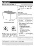
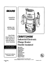
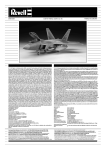
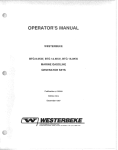
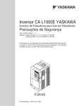
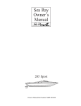
INSTALLATION & OPERATING INSTRUCTION MANUAL
GRAVITY VENTED FLOOR FURNACE
owner's manual
MODEL NOS:
4505622; 6005622
FOR USE WITH
NATURAL
GAS ONLY
MODEL NOS.
4505621
; 6005621
FOR USE WITH
LIQUEFIED
PETROLEUM
(L.P.)
60056
MODEL
SERIES
SHOWN
GAS ONLY
READ THIS OWNER'S
MANUAL CAREFULLY
BEFORE YOU INSTALL
YOUR NEW WILLIAMS
FLOOR FURNACE
manual is not followed exactly, a fire or excausing
property
l plosion
WARNING:may If result
the information
in this
damage, personal injury or loss of life.
--
--
WARNING: Improper installation,
adjustment, alteration, service or maintenance
can cause injury or property damage.
Refer to this manual. For assistance or
additional information consult a qualified
installer,
service
agency
or the gas
supplier.
WARNING:
Do not install any of these fur-
naces (Natural
homes, traders,
WILLIAMS
PRINTED IN USA 4/99
or L.P. Gas) in mobile
or recreational vehicles.
Furnace
--
Do not store or use gasoline or other flammable vapors and liquids in the vicinity
of this or any other appliance.
WHAT TO DO IF YOU SMELL GAS
• Open all windows.
• Do not try to light any appliance.
• Do not touch any electrical switch; do
not use any phone in your building.
• Extinguish any open flame.
• Immediately call your gas supplier from
a neighbor's phone. Follow the gas
supplier's instruction.
• if you cannot reach your gas supplier,
call the fire department.
Installation and service must be performed by a qualified installer, service
agency or the gas supplier.
Co., 225 Acacia
St., Colton, CA 92324
P322436
Your Warranty
The Manufacturer,
LIMITED
Williams Furnace Co.. warrants this wall furnace or heater to the original purchaser under the following conditions:
ONE.YEAR
WARRANTY
1. Any part thereof which proves to be defective in material or workmanship within one year from date of original purchase for use will be repaired or replaced at the
Manufacturer's option, FOB its tactory,
2, No liability is assumed by the Manufacturer for removal or installation labor costs, nor for freight or delivery charges,
LIMITED
EXTENDED
WARRANTY
1, In addition to the above limited one-year warranty on the complete unit, any heat exchanger which burns out or rusts under normal installation, use and service
conditions during a period of nine years following expiration of the one-year warranty period will be exchanged for a like of functionally similar part, FOB Manofacturer's factory,
2. No liability
is assumed by the Manufacturer for removal or installation labor costs, nor for freight or deliveP/charges,
LIMITATIONS
1. THIS LIMITED WARRANTY IS THE ONLY WARRANTY MADE BY THE MANUFACTURER.
_MPLIED WARRANTIES OF MERCHANTABILITY
OR FITNESS FOR
ANY PARTICULAR PURPOSE ARE LIMITED TO THE SAME ONE YEAR TERM AS THIS EXPRESS WARRANTY. UNDER NO CIRCUMSTANCES
SHALL THE
MANUFACTURER
BE LIABLE FOR INCIDENTAL, CONSEQUENTIAL.
SPECIAL OR CONTINGENT DAMAGES OR EXPENSES ARISING DIRECTLY OR INDIRECTLY FROM ANY DEFECT IN THE PRODUCT OR ANY COMPONENT OR FROM THE USE THEREOF. THE REMEDIES SET FORTH HEREIN ARE THE EXCLUSIVE
REMEDIES AVAILABLE TO THE USER AND ARE IN LIEU OF ALL OTHER REMEDIES,
Some states do not allow _imitations on how long an implied warranty lasts, and some states do not allow the exclusion or limitation
or consequential damages, so the above limitations or exclusions may not apply to you,
of iocidental
2. This warranty does not include any charge for labor or installation.
3, This warranty does not extend to painted sudaces nor to damage or defects resulting from accident, alteration, misuse or abuse, or improper installation.
4. This warranty does not cover claims which do not involve defective workmanship or materials.
DUTIES
OF THE CONSUMER
1, The heating equipment must be instafled by a qualified installer and operated in accordance with the installation and homeowner's instructions furnished with the
equipment.
2. Any travel, diagnostic costs, service labor, and labor to repair the defective unit will be the responsibility of the owner.
3, A bill of sale, cancelled check, payment record or permit should be kept to verify purchase date to establish the warranty period.
4. Have the installer enter the requested
information in the space below,
GENERAL
1. The Manufacturer
neither assumes nor authorizes any person to assume for it any other obligation or liability in connection
with said equipment,
2. Service under this warranty should be obtained by contacting your dealer. Provide the dealer with the model number, serial number and purchase date verification.
3. If, within a reasonable time after contacting your dealer, satisfactory service has not been received, contact: Customer Service Dedartmenf, 225 Acacia St., Cohort,
CA 92324, for assistance.
4. THIS WARRANTY GIVES YOU SPECIFIC LEGAL RIGHTS. AND YOU MAY ALSO HAVE OTHER RIGHTS WHICH VARY FROM STATE TO STATE.
INSTALLATION
Model
Orig.
INFORMATION
No.
Serial
No
Purchaser_
Address
City and State
Zip
Dealer
Address
City and State_
Zip
Installation date
Signed by.
.(Dealer or
authorized representative who certifies that this appliance has been installed in accordance with Manufacturer's instructions and
local codes,)
BUILDING CODES AND SAFETY STANDARDS
THE DESIGN OF THIS FURNACE IS NOT CERTIFIED
FOR USE IN MOBILE HOMES, TRAVEL
TRAILERS OR CAMPERS.
THIS FURNACE MUST BE PROPERLY VENTED TO THE OUTSIDE
FOR SAFE OPERATION.
DO NOT OPERATE THIS FURNACE WITHOUTAN
ADEQUATE VENTING
SYSTEM.
THE DESIGN
OF THIS APPLIANCE
COMPLIES
WITH ANSI Z21.48.
THE SECTIONS OF THIS MANUAL PERTAINING TO VENTING AND GAS PIPING PROVIDE ONLY
BASIC GUIDELINES.
BE SURE THE INSTALLATION
OF THE VENT AND GAS PIPING COMPLIES
WITH LOCAL CODES.
IN THE ABSENCE OF LOCAL CODES, BE SURE TO COMPLY WITH THE
NATIONAL FUEL GAS CODE ANSI Z223.1.
IMPORTANT
GENERAL
INFORMATION
Read these instructions completely before beginning the installation and use these instructions as a guide during the installation.
Your furnace has been carefully designed and constructed. The design of this furnace has been tested according to the
standards set by the American National Standards Institute, and the design has been certified by the American Gas Association
as conforming to these standards. Care has been taken to assure that your furnace will operate safely, efficiently, and
reliably, but your furnace must be properly installed. Only a licensed or otherwise qualified gas equipment installer should
install this furnace, the vent serving this furnace, and the gas piping. Installation procedures should comply with these
instructions and the latest edition of the American National Standard National Fuel Gas Code Z223.1. You should also refer
to any local codes or ordinances which may apply. Improper installation of the furnace, vents or gas piping, can subject you
and your property to fire, explosion, or asphyxiation hazards and will void the warranty offered by Williams Furnace Co. Do
not be satisfied with an improper installation.
Do not use this furnace if any part has been under water. Immediately call a qualified service technician to inspect the furnace
and to replace any part of the control system and any gas control which has been under water.
Safety Rules
WARNING
READ THESE RULES AND THE INSTRUCTIONS
CAREFULLY.
FAILURE TO FOLLOW THESE
RULES AND INSTRUCTIONS COULD CAUSE A
MALFUNCTION OF THE FURNACE. THIS COULD
RESULT IN DEATH, SERIOUS BODILY INJURY,
AND/OR PROPERTY DAMAGE.
4. LOCATE the furnace out of traffic patterns as much as
possible with a minimum of 6" clearance from all
combustible walls and 15" on two adjoining sides of the
grille for passage.
5. BE SURE to provide for adequate combustion and
ventilation air. The flow of this air to the furnace must not
be blocked.
INSTALLATION MUST CONFORM TO LOCAL CODES. IN
THE ABSENCE OF LOCAL CODES, INSTALLATION MUST
CONFORM WITH THE NATIONAL FUEL GAS CODE, ANSI
Z223.1.
6. USE joint compound (pipe dope) on threaded joints of gas
piping that is resistant to the action of liquefied petroleum
gas.
7. USE only ground joint unions in gas piping.
INSTALLATION AND REPAIR SHOULD BE DONE BY A
QUALIFIED SERVICE TECHNICIAN.
THE CLEANED
FURNACE SHOULD BE INSPECTED BEFORE USE AND
AT LEAST ANNUALLY BY A PROFESSIONAL SERVICE
TECHNICIAN.
MORE FREQUENT CLEANING MAY BE
REQUIRED DUE TO EXCESSIVE LINT FROM SOME
CARPETING,
BEDDING
MATERIAL,
ETC.
IT IS
IMPERATIVE
THAT CONTROL
COMPARTMENTS,
BURNERS AND CIRCULATING AIR PASSAGEWAYS OF
THE FURNACE BE KEPT CLEAN.
8. INSTALL a manual shutoffvalve and union ahead of the
controls so that the controls and furnace may be removed
for servicing, if necessary.
9. INCLUDE a 1/8 NPT plugged tapping accessible for test
gauge connection immediately upstream of the gas
supply connection to the furnace.
10. NEVER test for gas leaks with an open flame. Use soap
suds to check all gas connections. This will avoid the
possibility of fire or explosion.
YOUNG
CHILDREN
SHOULD
BE CAREFULLY
SUPERVISED WHEN THEY ARE IN THE SAME ROOM
WITH THE FURNACE.
11. INSTALL the furnace to a proper venting system
ANY SAFETY SCREEN, GUARD OR PARTS REMOVED
FOR SERVICING AN APPLIANCE MUST BE REPLACED
PRIOR TO OPERATING THE APPLIANCE TO AVOID
PROPERTY DAMAGE, BODILY INJURY OR DEATH.
12. DO NOT place clothing or other flammable material on
or near furnace.
CHILDREN AND ADULTS SHOULD BE ALERTED TO THE
HAZARD OF HIGH SURFACE TEMPERATURE
AND
SHOULD BE KEPT AWAY TO AVOID BURNS OR
CLOTHING IGNITION.
14. BE SURE factory
operation.
13. DO NOT modify or alter the furnace cabinet in any way.
installed
grille is in place during
15. DO NOT connect this furnace to a chimney serving a
solid-fuel burning appliance.
1. USE ONLY MANFACTURER'S
REPLACEMENT
PARTS. USE OF ANY OTHER PARTS COULD CAUSE
INJURY OR DEATH.
16. CLEAN the furnace and periodically inspect the pilot and
burner flame as described in the maintenance section of
this manual.
2. BE SURE furnace is for type of gas to be used. Check
the rating plate beneath the grille. Do not change it to
useothergases. Unsafe operation could resultandcould
cause bodily injury and death.
17. DISCONNECT
testing.
the furnace during supply line pressure
18. FOLLOWthe lighting and operating procedures given in
this manual.
3. BE SURE the furnace is installed so that the drafthood is
located in the same atmospheric pressure zone as the
combustion air inlet to the furnace.
19. WARNING: Any change to this furnace or its controls
could cause injury or death.
WARNING
DO NOT USE THIS HEATER IF ANY PART HAS BEEN UNDER WATER. IMMEDIATELY CALL A QUALIFIED
SERVICE TECHNICIAN TO INSPECT THE HEATER AND TO REPLACE ANY PART OF THE CONTROL SYSTEM
AND ANY GAS CONTROL WHICH HAS BEEN UNDER WATER.
-4.
/
|
J
KEEP THESE INSTRUCTIONS
All furnaces require a supply of oxygen for combustion. To
assure this furnace receives the necessary oxygen, two free
air openings of at least one square inch for each 1,000 BTU
per hour input rating of the furnace must be provided in the
foundation of the house (see figure 1). Be sure these openings
are located where the air can flow to the furnace and is not
likely to be blocked.
FOR FUTURE REFERENCE
Continued safe and satisfactory performance of this furnace
requires, but is not limited to, periodic examination of the vent
system, pilot flame, combustion chamber, liners and gas
supply lines and periodic cleaning of the burner air intake,
pilot and control areas. The venting system, including the
factory provided drafthood and all other parts of the vent,
must be inspected periodically for indicationsof failure, such
as loose joints, rusting components or broken parts. Any
defective or damaged part, which does not provide a
continuous conduit to carry the combustion products to the
outside, must be replaced before the furnace is operated. A
complete descriptionof the venting requirements iscontained
in the "Venting And Chimney Requirements" sectionof these
instructions.
This furnace is equipped with a temperature limit control
that limits the register temperature under normal conditions
of operations. This control may be overidden under unusual cimumstances, such as extremely cold weather, to allow
more heater output from this heater. A complete explanation of the operation of this control is contained in the
"Operating The Furnace" section of these instructions.
This furnace is designed to burn only the type gas that is
indicated on the rating plate, visible on the bracket directly
beneath the floor grille. Do not attempt to use this furnace
with any other type gas. If you are not sure what type gas is
available in your locality, obtain this information from your
local gas supply company.
An inspection of the furnace and attached systems should
be performed at least once each year by a qualified service
technician. More frequent inspections are advisable if the
furnace is installed or operated in a manner that might cause
the accumulation of dust or dirt in the furnace or the failure of
component parts more rapidly than would normally be
expected. Keep all combustible materials, gasoline and other
flammable liquids or vapors away from this furnace, and be
sure that combustion and ventilation air openings supplying
this furnace are kept clear at all times.
The pilotand control system of this furnace will automatically
stop the gas flow to the pilot burner and main burner if the
pilot flame is extinguished. This system also generates the
electricity required to operate the thermostat system. Since
no electrical power is required from any other source, this
furnace will continue to operate during a power outage•
FIGURE 1
VENTING
SECTION
MUST COMPLY WITH
OF THIS MANUAL.
"VENTING
AND
CHIMNEY
REQUIREMENTS"
HEADERS
FLOOR
(I/4"
FURNACE
RISE PER FOOT)
DEPTH
OF
FURNACE
T
IB" MINIMUM
WORK SPACE
OPENING
FROM
FURNACE PIT
12" MINIMUM ON ALL SIDES
EXC_T CONIROL END OF FURNACE
-5-
• 18" MINIMUM ON
CONTROL END OF FURNACE
Locating Floor Furnace
Consider the following points before attempting to install the
furnace:
1. To achieve the best results from this furnace, it must be
located in an area that will provide good circulation of air
to adjacent areas that need to be heated.
LIVING ROOM
BEDROOM
2. Warm air will rise from the furnace and travel to other areas
only through open doorways, and that air must return to
the furnace to be reheated.
AIR -
3. In small homes, one unit centrally located may be sufficient
to meet the heating requirements, but it is impractical to
attempt to use this furnace where heat must travel through
more than one doorway before reaching an area where
heat is desired. A typical installation of a single unit in a
small home is shown by Figure 2.
FLOOR
FURNA(
4. In larger homes, it may be necessary to use two or more
units to provide sufficient heat distribution. It is often better
to use two small furnaces rather than one large one.
KITCHEN
5. If there is a difference in the floor level between two rooms
to be heated, the furnace should be located in a room with
the lower floor.
DINING ROOM H
I
6. The flow of heat to various areas within the home can be
effectively regulated by the opening and closing of doors.
i
I
H
FIGURE 2
CLEARANCES
LOCATION NOTE
1.
Minimum clearance between the floor furnace and
adjacent walls - 6".
2.
Minimum
clearance
between furnace and doors,
draperies
or other combustible materials within the
home - 12".
3.
Minimum space required along two sidesof the furnace
to allow persons to walk around the furnace - 15".
Replacement floor furnaces of the same or lesser
Btu/h input rating may be installed in the same location
as the replaced furnace when such replacement does
not create an unsafe condition.
After you have selected a location that will provide the
necessary clearances and air circulation, check beneath the
house to be sure the clearances between the furnace and
the ground, as specified by Figure 1, can be obtained. It is
permissable to dig a shallow pit, as shown in Figure1, but a
pipe or trench should be provided to drain away any water
that may seep into the pit. If the depth of the pit must exceed
12", or if water seepage is likely, a watertight pit of galvanized
steel, copper, concrete or other suitable material should be
constructed and anchored intoplace to prevent itfrom floating.
The sides of this pan should extend four inches above the
The thermostat should be located on an interior wall far
enough away from the furnace to prevent it from being heated
directly by the furnace. Select a location in the area most
frequently used or best situated to control the temperature of
the entire house. Avoid locations where the thermostat might
be subjected to drafts from windows, doors, stairways, etc.,
or from other devices such as cooking ranges, fireplaces,
television, etc. Place the thermostat about five (5) feet above
the floor. Do not select a location that will require more than
25 feet of wire between the furnace and the thermostat. Do
not install the thermostat in an area which can be isolated
from the furnace by a door.
ground. The clearances between the upper rim of the pan
and the furnace should be no less than those specified in
Figure 1.
The width, length and depth of each furnace model is shown
in Figure 6.
-6-
Venting And Chimney Requirements
10. Be sure that there are no unsealed openings in the
vent or chimney that will decrease the chimney draft
and the chimney is at least 2 feet higher than all parts
of the building within 10 feet. This is required to
reduce the possibility of wind interfering with the draft
(see Figure 4).
11. If the furnace is to be vented into a masonry chimney,
be sure the chimney is lined, clean and in good repair.
12. Never terminate a vent pipe inside an attic, under
the building, in a closet or with a horizontal run of
vent pipe. The vent pipe must extend above the roof
of the building as shown in Figure 4.
Proper venting of this furnace is required to prevent the
release of hazardous gases into the dwelling. The furnace
must always be vented into a vertical vent. This vent may be
a listed type "B" gas vent or masonry chimney. The following
statements are intended as a guide for venting the furnace.
If other venting requirements are required by local codes,
the local codes must be adhered to.
If the furnace is to be vented into a masonry chimney, be
sure the chimney is lined, clean and in good repair. Be sure
the vent system is installed by a qualified installer and 1.
2.
3.
4.
5.
6.
7.
8.
9.
Do not connect this furnace to a chimney flue sewing
a seperate solid fuel (coal or wood) buming appliance.
Soot and creosote deposits from the solid fuel heating
appliance can block the vent serving this furnace.
If this furnace is to be connected to a chimney that
has previously been used for a solid fuel appliance,
clean the chimney thoroughly of all deposits that
might drop down and block the furnace vent.
The total length of the horizontal run of vent connector
pipe must not exceed 75 percent of the height of the
gas vent or chimney above the point where the vent
connector is attached. All venting material must be
supported by hangers spaced a maximum of four
(4) feet apart and attached to the floor joist or by
other methods approved by local codes.
The horizontal vent connector must be not less than
4 inches in diameter and not more than 6 inches in
diameter.
FIGURE
3
DRAFTHOOD
-- FLOORFURNACE
VENT PIPE2
[_
45°ELL
VENT
PIPEI
45" Y BRANCH.
DO NOT CONNECT
VENT PIPE TOGETHER
AT 90 °
ANGLES
The horizontal vent connector must slope upward
from the furnace to the chimney at least 1/4 inch per
foot of connector length.
Avoid using a vent or chimney for more than one
furnace if it is practical, but if it is necessary to use
one vent for two furnaces, be sure the vent or chimney
has an interior liner at least 6 inches in diameter.
If two furnaces are connected to a chimney or vent
with a common vent connector, join the unit connectors
as shown in Figure 3. Do not join the vent connectors
with a tee. Be sure to size the vent connectors as
shown in Figure 3.
Use a thimble when attaching the vent connector to
a masonry chimney, and place the thimble at least 6
inches above the bottom of the chimney. Seal the
vent connector and thimble joint to prevent gases
from escaping.
Keep the vent connector at least 6 inches from all
combustible material and if the vent connector must
pass through a partition constructed of combustible
materials, use a thimble in the partition that has been
listed for this use by a nationally recognized testing
agency. An improperly installed vent connector can
overheat adjacent materials and cause a dangerous
fire.
"'Y" CONNECTION
NO MORE
12"' FROM VERTICAL
FLeE
DO NOT EXTEND VENT
INSIDE OF FLUE LINER
Size Vent Pipe 1
4""
56-
WRONG
VENT
THAN
PIPE
FLUE
PIPE PAST
Size Vent Pipe 2
4"'
5"
6""
Size Vent Pipe 3
6'
7""
8'
RIGHT
13. Do not use an uninsulated vent pipe. An uninsulated
vent pipe can cause a fire hazard by overheating
adjacent combustible matedals. An uninsulatedvent
pipe can also cause condensation of the vent gases
within the pipe and retard the draft.
-7-
Gas Supply And Piping Requirements
Gas pipe must be installed by a qualified installer. The pipe
system must comply with the latest edition of the American
National Fuel Gas Code Z223.1. Figure 5 depicts the required
pipe arrangement at the furnace. The drip leg is required to
prevent condensate and scale particles from entering the
furnace controls. The union is required to allow the control to
be removed for servicing. All unions in gas pipe systems
shall be of the ground joint type. Use a pipe joint compound
that is resistant to liquified petroleum gases (LPG). Do not
locate pipe joints in a concealed location where leak detection
and repairs are difficult or impossible.
The maximum inlet supply pressure for this furnace must
be 7 inches for natural gas and 13 inches for LP gas. The
minimum inlet supply pressure for the purpose of input
adjustment must be 5 inches for natural gas and 11 inches
for LP gas. The control on this furnace is equipped with a
regulator which reduces the manifold pressure to 4.0 inches for natural gas and 10.5 inches for LP gas.
If the furnace is equipped for LP gas, the gas tank must be
provided with a regulator which will reduce the line pressure
to the furnace to between 11 and 13 inches water column.
Unregulated LP gas pressure will damage the control and
cause it to leak hazardously
CAUTION:
The furnace and its individual shutoff valve must
be disconnected from the gas supply piping system during
pressure testing of that system at test pressures in excess of
1/2 psig The furnace must be isolated from the gas supply
piping system by closing its individual manual shutoff valve
during any pressure testing of the gas supply piping system
at test pressures equal to or less than 1/2 psig Pressures in
excess of 1/2 psig will cause damage to the control valve
and may cause damage to the shutoff valve.
ROOM
GRILLE
FIRST
FLOOR
r.
m
STUD
FLOOR
@
FRAME
FURNACE
p
LIMIT SW1TCH
LEAD V_RES
_
DRIP
LEC_-CAP
f
I
I
_--UNtON
HERMOSTA"
k
" SHUT-OFF
VALVE
CONTROL
VALVIZ
FIGURE 5
UNPACKING
AND
Remove the furnace from the carton and inspect carefully
for shipping and handling damage or missing parts Report
any damage or missing parts to your Williams dealer and
INSPECTION
be sure all problemsare resolved before installingthe furnace
DO NOT INSTALL A DAMAGED FURNACE. A furnace
that is damaged or in poor repair can be hazardous
8-
Installation
1.
2.
3.
4.
5.
6.
7.
8.
9.
19. Install the thermostat and connect the thermostat lead
wires to the limitswitch and control as shown in Figure 8.
Lay an outline of the furnace in the selected location,
and draw diagonally from each corner of the outline as
shown in Figure 6.
Drive a nail through the flooring at the intersection of the
diagonal lines.
Use the nail location as a reference, and examine the
area beneath the floorto assure there are no obstructions
that will prevent the installation of the furnace and that
adequate clearance between the furnace and the ground
can be obtained. If the selected location of the furnace is
FIGURE
1" DIA. HOLE
6
FOR STARTING
LOCATION. DRIVE NAIL
THROUGH FLOORTO
LOCATECENTER
UNDERNEATH,
appropriate, proceed to step 4.
Bore two 1" diameter holes in opposite corners of the
furnace outline. Be sure the holes do not extend beyond
the furnace outline.
Insert a compass or sabre saw into one of the 1"diameter
holes and cut along the furnace outline. Cut as straight
and accurately as possible to avoid any possibility the
hole will not fit the furnace or willextend beyond the outer
perimeter of the furnace grille after it is installed.
If itis necessary tocutflcorjoists to installthefurnace, install
headers across the cut ends of the floor joists, and double
the floor joists along each side of the furnace cut-out as
shown in Figure 7. If you must cut a girder or beam,
constructan adequate foundationand pillarto supporteach
end of the cut member.
If necessary, dig a pit and install a pan in the ground
beneath the furnace to provide the required clearances.
Remove the grille from the furnace.
Lower the furnace into the floor opening until the flanges
on the furnace cabinet rest on the floor.
MODEL NUMBER
4505621;
6005621;
4505622
6005622
WIDTH
=
=
24-1/4
24-1/4
LENGTH
32-3/8
42-5/8
11. Fasten the furnace in place by driving nails through the
sides of the furnace cabinet and into the floor joists.
12. Refer to Figure 10 on page 11 for the installation of
drafthood collars and the drsfthood.
13. Install the (2) drafthood collars and gaskets by
positioning the collars into the (2) retangular openings
on the furnace, making sure gaskets are facina toward
DEPTH
28
28
FIGURE
NOTE :
IF TWO JOISTS
CUT,
HEADIER.
14. Slipthe (2) drafthoodcollars over the combustion chamber
outlets and engage the collars into the furnace until the
gaskets press tightagainst the furnace. Secure the collars
to the furnace with (12) screws previously removed.
15. Check to be sure the drafthood collars fit snugly over the
combustion chamber outlets.
16. Install the drafthood by positioning the drafthood with
open side down. Slip over the drafthood collars making
sure the drafthood collars engage into the drafthood.
Secure the drafthood to the furnace with (4) screws
previously removed.
17. Install the pipe necessary to connect the furnace to the
gas vent or chimney. Be sure to comply with all the
requirements for proper venting as stated in the "Venting
and Chimney Requirements" section of this manual.
18. Connect the furnace to the gas supply line as specified
by the "Gas Supply and Piping Requirements" section of
this manual (see Figure 5).
ARE /
T_S
THE
THE
-9-
7
SPACE MUST BE
SAME
SIZE AS
OPENING
CUT
Installation (cont.)
21. Refer to the "Lighting and Operation" section of this
manual. Carefully read the safety information, then light
the pilot and main burner according to the instructions.
Allow the main burner to burn for five minutes,
see Figure 11 for typical burner flame pattern.
20. Turn on the gas and check all gas fittings for leaks with a
soapy water solution or a liquid leak detection solution.
DO NOT USE A FLAME TO CHECK FOR LEAKS.
The use of a flame for leak detection can cause a
dangerous explosion
FIGURE 8
DIAGRAM
FOR 450
OF WIRING CONNECTIONS
&: 600 FLOOR FURNACE
UMIT
THERMOSTAT
VALVE
oo.,.o,
vALv_ I
I Ca_E"ATO"
I
L
AUX
_,F.".%"_T,T
I
, o'1
I GEN
O
I L_M,T
I
.o_:
DO
-10-
NOT
CONNF.CT
TO
UNF"
VOLTAGE.
Installation (cont.)
22. Check the vent or chimney performance by holding a
match near the edge of the drafthood as shown in Figure
12. If the flame is not pulled into the drafthood, the
chimney is not providing sufficient draft. This can allow
hazardous gases to escape the vent system. Find and
correct the causes of this malfunction.
23. Replace the grille on top of the furnace. The small clip
attached to the chain at the limit switch box should be
hung over a section of the grille so it can be used to
override the limit switch as described in the "Operating
the Furnace" section of this manual.
Explain the
operation of the furnace to the homeowner and give
these instructions to the homeowner.
FIGURE 11
FIGURE
/_
[
12
FIGURE 9
-- _N_ATOR
1 1/8"
TO 1 I/4"
PILOT
PROPER FLAME
ADJUSTMENT
1/4" m _/8"
FIGURE 10
DRAFTHOOD_.
COLLAR
\
-UFURNACE
/DRAFTHOOD
/COLLAR GASKET
TER CASING
___
.....
\
/
/
(OPEN SIDE
""'_I
,
-
--_:'_--
CHAMBER
I
"
\
ASSEMBLY _
FLUE OUTLET
FLUE
OUTLET
----
I
i
o.
I
I
DRAFTHOODJ
COLLAR
ASSEMBLY
_- DRAFTHOOD
COLLAR GASKET
PLAN
-11-
VIEW
I
%
/
\
.........
J
_-
COMBUSTION
CHAMBER
ASSEMBLY
FOR YOUR
I
SAFETY
READ
If youresult
do not
follow property
these instructions
exactly, injury
a fire or
or loss
explosion
may
causing
damage,
personal
of life. I
which must be lighted
by hand.
When lighting
the pilot, follow
these
instructions
exactly.
B. BEFORE LIGHTING
smell all around the appliance
for gas.
Be sure
because
some
gasis
settle on the floor.
to smell
next
to the floor
heavier
than
air and will
• If you cannot reach your gas supplier, call the fire
department.
C, Use only your hand
control
rod.
Never
•
Do not try to light
any appliance
or strike
a match.
•
Do not touch any electric switch; do not use any phone
in your building.
gas
will
may result in a fire or explosion.
technician
to inspect
if any part has been
call a qualified
service
the appliance
and to replace
any part of the control
system
and
control which has been under water.
any
gas
INSTRUCTIONS
1.
STOP! Read the safety information
this label.
2.
3.
Set the thermostat to lowest setting.
With the key, depress the control rod slightly
and turn pointer clockwise
repair
O. Do not use this appliance
under water.
Immediately
Immediately call your gas supplier from a neighbor's
phone. Follow the gas zupplier's instructions.
OPERATING
to push in or turn the
use tools.
If the knob
not push in or turn by hand, don't try to repair
it, call a qualified
service
technician.
Force or
attempted
WHAT TO go IF YOU SMELL GAS
•
LIGHTING
I
WARNING:
A. This appliance has apilot
area
BEFORE
above on
Push the ignitor button again at five (5) second
intervals until the pilot is lit. After the pilot is lit,
continue
to hold the control
rod down for
about one (1) minute.
Release the control rod
_> to"OFF".
and it will pop back up. The pilot should remain
lit. If it goes out, repeat steps 2 through 7.
IGNITOR
Alternate liQhtinq with a match:
Fol[ow steps
PILOT
CONTROL
BUTTON
2 through 6. Remove cover from observation
ROD
_
POINTER
_'_
hole. Place a match in lighter rod, ignite and
z
lower to pilot burner (through observation hole).
O
Depress the control rod down fully and hold it
4. Wait five (5) minutes to clear out any gas.
down for about one (1) minute after the pilot
Then smell for gas, including near the floor.
lights.
Release the control rod and it will pop
If you smell gas, STOP!
Follow "B" in the
back up. The pilot should remain lit. If it goes
safety
information
above
on this label.
out, repeat steps 2through 7. Replace cover on
If you don't smell gas, go to the next step.
observation hole, making sure gasket is in place.
5. Find the pilot.
• If the pilot will not stay lit after several tries,
depress the gas control rod slightly and turn
PILOT -_
HoLEOBSERVATION to "OFF", and call your service technician or
gas supplier.
6. Turn the control rod counterclockwise
<_
• If control rod does not pop up when released,
to "PILOT',
stop and immediately call your service technician.
7. Position yourself
so the pilot can be seen
8.
Turn
the control rod counterclockwise<_
to
through the observation hole. Push the control
-ON +"
rod down fully and hold it down. Immediately
push the ignitor button.
9. Set thermostat to desired setting.
TO TURN
OFF GAS
1. Set the thermostat to lowest setting,
2. With the key, depress the control rod slightly
-12-
TO APPLIANCE!
and turn clockwise
_> to "OFF'.
Operating The Furnace
Always follow the instructions located beneath the furnace
grille when lighting the pilot. To set the thermostat, turn the
temperature selector to the highest setting until the heated
area reaches the desired temperature, then move the selector
slowly toward a lower setting until the furnace control cycles
off the burner. At this setting, the furnace should cycle on
and off as required to maintain the desired temperature.
WARNING
THE SURFACE OF THE FURNACE IS HOT DURING
OPERATION.
KEEP CHILDREN,
CLOTHING,
FURNITURE AND FLAMMABLE MATERIAL AWAY
FROM THE FURNACE.
How To Care For Your Furnace
Service, repair or maintenance of the furnace, vent or gas
system should only be attempted by a qualified service
technician.
The burner and control of the furnace should be cleaned and
checked at least once each year by a qualified service
technician. If there is any indication that the furnace is
operating improperly, turn it off and have it checked
immediately.
Lint and dust may be vacuumed from the interior of the
furnace, when it is cool, by removing the floor grille. The
control and main burner can be blown free of dust and lint
with a vacuum cleaner.
WARNING
FLAMMABLE LIQUIDS OR VAPORS NEAR THE
I DO
NOT STORE OR USE GASOLINE OR OTHER
FURNACE.
This furnace is equipped with a control that limits the temperature of the furnace grille by cycling the main burner.
This control may be overridden to allow more heat output
from the furnace during extreme weather when the furnace
will not provide sufficient heat otherwise. The overide
mechanism is located beneath the grille onthe control end.
To override the temperature limit control, pull up on the
chain attached to the grille until the flap bearing the
"Register Hot--" warning is in the horizontal position. Insert
chain through slot to the side of the flap to hold flap in the
horizontal position (see Figure 13). To reactivate the tamperature limit control, remove chain from slot and the flap
will hang down. Do not override the temperature limit control if the furnace is in an area occupied by children or
elderly persons who could fall on the furnace and be
burned.
If the combustion chamber must be removed for servicing 1. Turn the gas off at the main gas line shut-off valve.
2. Remove the floor grille and lift out the inner casing.
3. Lift the control end of the combustion chamber slightly,
slide the chamber toward the end of the cabinet about
one inch and then lift it out of the cabinet.
WARNING
DANGER OF BODILY INJURY OR DEATH
DO NOT OPERATE THE FURNACE WITH A
BROKEN OR MISSING PILOT OBSERVATION
DOOR.
If the control and main burner assembly must be removed
for servicing 1. Turn the gas off at the main shut-off valve.
2. Disconnect the union in the gas supply line_
3. Remove the thermostat control wires from the gas control.
4. Remove the nuts that attach the gas control to the furnace
outer casing.
5. Remove the control assembly.
6. Remove the screw that attache s the control end of the
burner to the outer casing.
7. Slide the bumer forward until the control end of the bumer
FIGURE 13
ca n be dror)ped dow n and pul! the burne[ OUtof the outer
casing.
This should be done by a qualified service technician.
If the furnace will oot be used for a long period of time, turn
the control knob to the "OFF" position and turn off the shutoff valve in the gas line serving the furnace.
-13-
Troubleshooting
SYMPTOM
1. Flame too large.
2. Noisy flame.
3. Yellow tip flame.
4, Floating flame.
5. Delayed ignition.
6. Failure to ignite.
7. Burner won't turn off.
8. Rapid burner cycling.
9. Burner won't turn on.
Floor Furnace
POSSIBLE CAUSE
CORRECTIVE ACTION
A. Pressure regulator set too high. Reset, using manometer.
B. Defective regulator.
Replace.
C. Burner orifice too large.
Replace with correct size.
A. Too much primary air.
See Item 1.
B. Noisy pilot.
Reduce pilot gas.
C. Burr in orifice.
Remove burr or replace.
A. Too little primary air.
Look for obstructions in air path.
B. Clogged burner ports.
Clean ports.
C. Misaligned orifices.
Realign or replace burner.
D. Clogged drafthood.
Clean.
A. Blocked venting.
Clean.
B. Insufficient primary air.
Look for obstructions in air path.
A. Improper pilot location.
Reposition pilot.
B. Pilot flame too small.
Check orifice, increase gas.
C. Burner ports clogged.
Clean ports.
D. Low pressure.
Adjust pressure regulator.
A. Main gas off.
Open manual valve.
B. Defect in gas valve.
Replace.
C. Defective thermostat.
Replace.
A. Poor thermostat location.
Relocate thermostat.
B. Defective thermostat or wiring.
Replace or repair.
C. Defective control valve.
Clean or replace.
A. Poor thermostat location.
Relocate.
B. Defective thermostat.
Replace.
A. Defective control valve.
Replace.
B. Defective thermocouple.
Replace.
C. Defective thermostat.
Repair or replace.
D. Defective limit switch.
Replace.
(continued next page)
-14-
Troubleshooting
SYMPTOM
10. Not enough heat.
Floor Furnace cont.
POSSIBLE CAUSE
A. Thermostat set too low.
Raise setting.
B. Appliance close to thermostat.
Move heat source away.
C. Thermostat in bad location.
Relocate thermostat.
JD. Thermostat out of calibration.
11. Too much heat.
CORRECTIVE ACTION
Recalibrate or replace.
A. Thermostat set too high.
Lower setting,
B. Thermostat out of calibration.
Recalibrate or replace.
C. Valve sticks open.
Replace valve.
D. Thermostat in draft.
Relocate thermostat.
-15-
REPLACEMENT
PARTS FOR MODELS
4505621
4505622
6005621
6005622
KEY
NO.
DESCRIPTION
4505621
4505622
6005621
6005622
1
GRILLE, FLOOR
P322426
P322428
P322429
P322429
2
INNER LINER ASSY
480041
480041
480042
4B0042
3
L.H. SECONDARY CHAMBER
480056-1
4B0056-1
4B0057-1
4B0067-1
4
COMBUS_ON
480046
4B0046
4B0047
4B0047
5
R.H. SECONDARY CHAMBER
480056-2
480056-2
480057-2
4B0057-2
6
OUTER SHIELD ASSY
480036
4B0036
4B0069
480069
7
PEEP HOLE COVER ASSY
12840
12B40
12840
12B40
8
IGNITOR
P285500
P285500
P285500
P285500
9
S_TCH,
P322430
P322430
P322430
P322430
10
KEY, CONTROL
P322445
P322445
P322445
P322445
11
ROD, CONTROL
4A0037
4A0037
4A0037
4A0037
12
ROD, LIGHTER
P322431
P322431
P322431
P322431
13
_RE,
P017000
P017000
P017000
P017000
14
THERMOSTAT
P322016
P322016
P322016
P322016
15
CHAMBER
LIMIT
THERMOSTAT
CONTROL VALVE NAT.
P322425
P322425
CONTROL VALVE LP.G.
P322426
16
BRACKET, VALVE
480019
4B0019
480019
4B0019
17
MANIFOLD ASSY
4A0012
4A0012
4A0012
4A0012
PILOT NAT.
P322426
P322274
P322274
18
PILOT L.P.G.
P322275
P322275
19
SHIELD, BURNER
4B0014
4B0014
480010
4B0010
20
BURNER
P322417
P322417
P322418
P322418
21
GASKET, FLUE OUll..ET
P322439
P322439
P322439
P322439
22
DRAFI!-IOOD COLLAR ASSY
4B0072
480072
4B0072
4B0072
23
DRAF1]-IOOD ASSY
4B0026
480026
4B0026
480026
24
ENVELOPE ASSEMBLY
4B0024
4B0024
4B0024
4B0024
FOR PARTS ILLUSTRAllON, SEE PAGE 17
USE ONLY MANUFACTURES AUTHORIZED PARTS
NOTE: Screws,
bolts and washers ore standard
-16-
hardware
items
and may be purchased
locally
WILLIAMS
GAS FIRED
FLOOR FURNACE
REPLACEMENT
PARTS FOR
450 & 600
MODEL SERIES
(FLOOR
FURNACE)
FOR PARTS LISTING
SEE PAGE 16
USE ONLY MANUFACTURERS
AUTHORIZED PARTS
60056
NOTE:
-17-
MODEL SERIES SHOWN
ITEMS 10, 13, 14 &: INSTALLATION
INSTRUCTIONS
(NOT SHOWN) ARE
CONTAINED IN ITEM 24.
Notes
Notes
Service
Hints
If your furnace fails to work right, you may avoid inconvenience
and the cost c
a service call by checking
the following
points before you call for service.
FOR YOUR SAFETY
owners
manual
MODEL NOS.
FOR NAT. GAS ONLY
4505622; 6005622
MODEL NOS.
FOR L.R GAS ONLY
4505621;6005621
Do not store or use gasoline
or other flammable
vapors and
liquids in the vicinity of this or any
other appliance.
POSSIBLE
CAUSE
FOR YOUR SAFETY
If you smell gas:
1. Open windows.
2. Don't touch electrical.
3. Extinguish any open flame.
4. Immediately call your gas
supplier.
WHAT TO DO
If your heater is not heating or not giving enough heat -Thermostat is not set correctly.
Pilot is out.
Reset thermostat to desired setting.
Check pilot. Relight if necessary
following instructions for "Operating
Your Heater."
Pilot is on but burner won't
come on.
If gas valve is set at other than "On"
heater will not operate. Shut heater
down and follow instructions for
relighting in "Operating Your Heater"
section.
Burner is not operating
properly.
Check flame. If it is yellow the burner
is not getting enough air. Or if flame
is blue and noisy and seems to lift off
the burner, the burner is getting too
much air.
Pilot goes out time after time -Heater flue blocked.
If burner is noisy -Gas input amount is incorrect,
Too much primary air.
Locate vent outlet blockage and
clean.
Contact Williams Service Department.
Contact Williams Service Department.
See troubleshooting section for more detailed information.
How to Order
When ordering repair parts, always give the following
information:
1.
2.
3,
4.
MODEL NUMBER
MFG. DATECODE
PART NUMBER
PART DESCRIPTION
©1999 The Williams Fumace Company
Repair
Parts
All parts listed herein may be ordered from your equipment
supplier.
The Model Number of your Williams floor furnace will be
found on the rating plate, visible on the bracket directly
beneath the floor grille.
WILLIAMS FURNACE COMPANY
225 Acacia Street
Colton, CA 92324 USA
MANUFACTURED
IN THE U,S.A.
Established 1916
(9o9)82s-0_3
FAX: (909) 824-8009
Printed in U.S.A.
Rev. 4/99
P322436