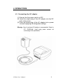
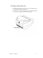
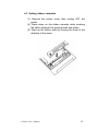
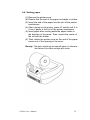
1
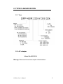
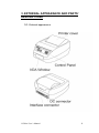
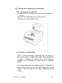
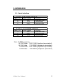
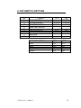
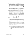
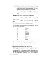
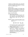
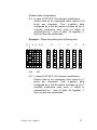
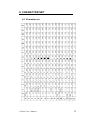
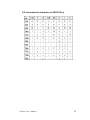
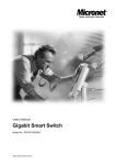
USER’S MANUAL
CGPrint mini printers
CGP ELECTRONICS KFT.
HUNGARY
CONTENTS
1. INTRODUCTION .............................................................3
1.1. Features ..................................................................3
1.2. Accessories .............................................................3
2. TYPE CLASSIFICATION .................................................4
2.1. Type........................................................................4
2.2. AC adapter...............................................................4
2.3. Specification ............................................................5
3. EXTERNAL APPEARANCE AND PARTS’ DESCRIPTIONS 6
3.1. External appearance.................................................6
3.2. Control Panel ...........................................................7
4. OPERATIONS ................................................................8
4.1. Connecting the AC adapter........................................8
4.2. Setting of the printer cover .........................................9
4.3. Setting ribbon cassettes.......................................... 10
4.4. Setting paper.......................................................... 11
4.5. Change and charge the accumulator......................... 12
4.5.1. Change the accumlator...................................................12
4.5.2. State of accumulator .......................................................12
4.5.3. Charge the accumulator .................................................13
4.6. Power managenemt ................................................ 13
4.7. Self test printing ..................................................... 14
4.8. General notices ...................................................... 14
5. INTERFACE ................................................................. 15
5.1. Serial interface (DP and TP type) ............................. 15
5.2. Serial interface (DPP and TPP type)......................... 15
6. DIP SWITCH SETTING.................................................. 16
7. CONTROL COMMAND.................................................. 17
7.1. Print control commands .......................................... 17
8. CHARACTER SET........................................................ 22
8.1 Character set .......................................................... 22
8.2 International character set (ESC+R+n)....................... 23
CGPrint User’s Manual
2
1. INTRODUCTION
Portable or desktop: The CGPrint series may be used
as a desktop/wall-hung unit or as a hand-held/belt-hung,
battery-operated unit to meet a wide variety of needs. It is
ideal for EFT (electronic fund transfer) and POS (point of
sales) transactions, in-the-field receipting and other
applications that require a small foot print and/or portability.
It also offers in-vehicle receipting for taxi and other public
transportation provides.
Impact and thermal: The CGPrint series also offers a
choice of printing technologies – impact dot matrix and
direct line thermal option are available.
Wide interface range: The CGPrint series also offer for
RS-232C serial interface, Serial TTL interface, and Infrared
communication interface (IrDA)
Warning :Please read this manual to understand the printer before use !
1.1. Features
-
Portable and/or Desktop applications
Impact or thermal print option
RS-232C, TTL serial or IrDA interface
57 mm wide paper
Paper end detector
Text and graphics mode
OEM version available
Customised case colours
1.2. Accessories
- Paper roll
- Ribbon cassette (only on dot matrix)
- AC adapter
- User’s Manual
- Accumulator (only on portable type)
CGPrint User’s Manual
(1 roll)
(1 pc.)
(1 pc.)
(1 pc.)
(1 pc.)
3
2. TYPE CLASSIFICATION
2.1. Type
2.2. AC adapter
Model No:MW1208
Warning: Please use the exclusive adapter indicated below !
CGPrint User’s Manual
4
2.3. Specification
CGPrint User’s Manual
5
3. EXTERNAL APPEARANCE AND PARTS’
DESCRIPTIONS
3.1. External appearance
CGPrint User’s Manual
6
3.2. Control Panel
CGPrint User’s Manual
7
4. OPERATIONS
4.1. Connecting the AC adapter
(1) Ensure that the power switch is OFF.
(2) Insert the output plug of the AC adapter into the DC
jack of the printer.
(3) Insert the power plug of the AC adapter into a power
consent supplying the designated voltage.
Warning : Use of exclusive AC adapter is recommended. Output is
DC 12V/8OOmA. Avoid using power sources not
conforming to this specification.
CGPrint User’s Manual
8
4.2. Setting of the printer cover
(1) Hold the protruding section at the rear of the printer cover
and lift in the direction indicated.
(2) Attach the cover by pressing downward after hooking the
cover to the acceptor located in the front part.
CGPrint User’s Manual
9
4.3. Setting ribbon cassettes
(1) Remove the printer cover after turning OFF the
printer.
(2) Press down on the ribbon cassette while inserting
the ribbon between the printing head and platen.
(3) Wind up the ribbon slack by turning the knob in the
direction of the arrow.
CGPrint User’s Manual
10
4.4. Setting paper
(1) Remove the printer cover.
(2) Ensure that the end of the paper is straight or incline.
(3) Insert the end of the paper into the slot of the printer
mechanism.
(4) After turning on the printer, press LF switch until 5 to
6 cm of paper is fed out of the printer mechanism.
(5) Insert paper after moving aside the paper holder in
the direction of the arrow. Then, secure the center of
the roll with the holder.
(6) Then, attach the printer cover so the end of the paper
comes out of the opening in the cover.
Warning : The device should only be used with paper in it otherwise
the lifetime of the ribbon cartridge gets shorter.
CGPrint User’s Manual
11
4.5. Change and charge the accumulator
4.5.1. Change the accumlator
(1) Remove the accumlator cover after the turn Off the
printer
(2) Insert the accumulator plug of the printer.
(3) Remove the accumlator cover.
4.5.2. State of accumulator
State of the accumulator signalizing the tree lamp on
the control panel. If lighting the green lamp accumlator
is ready, if lighting the yellow lamp the accumlator
medium and is lighting red lamp need the charging
period.
This lamp signalizing the charging period. If blinking the
green lamp printer is turn ON and making the normal
charge. If the rounding the tree lamp making the quick
charge.
CGPrint User’s Manual
12
4.5.3. Charge the accumulator
This products has a quick accumulator charger inside. If
the accumulators too low occur insert the output plug of
the AC adapter into the DC jack of the printer. The
lighted lamp indicates the right connection. After 1 hours
accumulators 70% and more than 2 hours needed to
approx. 100% charged state.
Proposition : Always charge the unit overnight when
charging to obtain a full charge. NiCd accumulators have
an inherent "memory". Unless they are fully charged
each time, the accumulators pack's charge life will be
limited. Discharge the accumulators as fully as before
recharging it.
Note 1: If you using CGPrint printer with optionally ordered NiMH
accumulator the "memory" affect not appear, discharge
accumulators as fully as possibility not necessary and the
capacity and printing time with one charge is 60%
higher.
Note 2: If you order the printer NiCd accumlator never use the
printer NiMH accumlator.
4.6. Power managenemt
In most of application which contains printer the printer
works only short time of operation, but it is power ON
under full operation. If the printer works in line powered
mode it isn't problem, but case of battery operation it is,
because the continuously power consumption decrease
the energy of battery.
If DIP-5 switch ON may be turn On the printer DTR
signal. If DIP-6 switch On may be turn On the printer via
IrDA connection.
CGPrint User’s Manual
13
4.7. Self test printing
A self-printing function is in corporate in this product to
enable the printer to check itself. This function works
only in "manual control mode" (DIP4 OFF) and is
triggered by the following procedure.
(1) Set paper to the printer.
(2) Ensure that the ribbon cassette is attached correctly
and turn the power OFF.
(3) Turn ON the power switch while holding the LF
switch down. Release the LF switch after the selfprinting operation has started.
Printing is initiated by this operation. To end selfprinting, turn OFF the printer.
4.8. General notices
- Never operate your printer without loading paper and
ribbon cassette. Any printing without paper and ribbon
cassette may cause damage to printer head.
- Replace ribbon cassette before it is worn with rents.
- Be careful not to drop any foreign matters, such as
paper clips, pin and the like into your printer. Those
can cause mechanical trouble.
- Nothing shall be placed on the radiation vents to the
printer.
- No organic solvent /thinner, benzin or the lie/ shall be
used in sweeping clean the surface of the main body
case.
CGPrint User’s Manual
14
5. INTERFACE
5.1. Serial interface
9 PIN D_SUB Female connector
Signal PIN Signal Name
Function
2
RxD
Received Data
4
DTR
Printer Busy
5
GND
Signal Ground
25 PIN D_SUB Female connector
Signal PIN Signal Name
Function
3
RxD
Received Data
7
GND
Signal Ground
20
DTR
Printer Busy
Note : D-SUB connector
25 PIN Printer : 17LE-13250 (Amphenol equvivalent)
25 PIN Cable : 17JE-23250 (Amphenol equvivalent)
9 PIN Printer : 17LE-13090 (Amphenol equvivalent)
9 PIN Cable : 17JE-23090 (Amphenol equvivalent)
CGPrint User’s Manual
15
6. DIP SWITCH SETTING
No.
1
2
3
4
5
6
7
8
Funkció
Printer RESET
Printing direction
Baud rate selection
Baud rate selection
Turn On by DTR
Turn On via IrDA
Not Used
Not Used
Baud rate selection
9600
4800
57600
19200
CGPrint User’s Manual
OFF
Normál
ON
RESET
Inverted
OFF
OFF
ON
ON
DIP3
OFF
OFF
ON
ON
DIP4
OFF
ON
OFF
ON
16
7. CONTROL COMMAND
7.1. Print control commands
1. Printing command (CR)
If selection code CR (0Dh) is inputted, data in print
buffer is printed and paper feed is performed when
serial data is inputted. When graphic (mosaic)
printing is performed, line feed is not performed by
the print command, and graphic printing is allowed
on the next line.
2. Cancellation command for input data (CAN)
If CAN code (18h) is inputted, all data which are
inputted before CAN code (18h) on the same line are
canceled.
3. Enlarged character printing (SO)
Input SO (0Eh) code with arbitrary columns, then the
following data is printed with double width enlarged
characters. The number of columns entered when all
the characters are shown in Table.
UP-24
12 digits
UP-40
20 digits
This function is released by inputting a print
command (CR) or DC4 (14h) code.
4. Escape alphabet control commands
The following function setting occur with the input of
ESC (1Bh) code and the following alphabet code.
Also, n after the alphabet code indicates an 8 bit
binary value. "+" is used as a separator for
convenience and should not
be entered as data.
Note: When an Escape Alphabet Command is inputted in the
middle of a line, data previously entered is printed, then the
previous sequence is terminated.
CGPrint User’s Manual
17
4/a. Set spacing between lines (ESC+A+n)
Dot line space setting is determined by entering the
code ESC+A+n. Initial setting is 2 dot line space.
The n should be an even number in the range of 0 < n
<255.
Note: If an odd number is entered, the dot line is set to "n-1".
Continuous printing is enabled by specifying n=0 or 1.
4/b.Bit image data translation (ESC+K+n1+n2+n3)
By entering ESC+K+n1+n2+n3, print mode is
swiched from the text mode to bit image mode. n1,
n2 and n3 indicate the transmission volume of the bit
image data to follow. That is, n1 indicates the
horizontal byte while n2 and n3 signify the vertical
dot lines (n3 x 256 + n2).
UP-24
UP-40
n1
1-18
1-23
n2
0-255
0-255
n3
0-1
0-1
In case a parameter beyond the specificable range is
specified, and if n2=n3=0 is specified, the bit image
mode is canceled and the printer returns to text
mode.
As this printer prints out 4 dot lines as one unit, the
lacking data is output as space once the data for 4
dot lines are read in or the output of data specified in
n1, n2 and n3 has finished.
Note 1: If n1=23 is specified in UP-40/X specification, 4 dots from
the topmost dot become invalid. This is due to the fact
that the output position for a single line consist of 180
dots.
CGPrint User’s Manual
18
Note 2: Although the printer return to text mode when bit image
mode printout is completed, line spacing is set to 0 to
enable further output in the bit image mode. Line feed is
required in order to commence text mode output.
For bit image printing, inverted printing is not performed
but normal printing, even if the DIP switch 1 is set to
"ON".
Example: UP-24/X 1 dot line full dot printing
1Bh
4Bh
12h
01h
00h
FFh......FFh
ESC + K + n1 + n2 + n3
total 18
data
4/c. International character set (ESC+R+n )
The following characters are set for a specified country
by ESC+R+n code input.
n
0
1
2
3
4
5
6
7
8
country
USA
France
Germany
England
Denmark
Sweden
Italy
Spain
Japan
An n other than the specified n is invalid, and the
previous n becomes valid. n = 0 (America) occurs
when power is applied.
4/d.Character registration (ESC+&+A1+A2)
Individual patterns can be registered by entering the
code ESC+&+A1+A2, then entering the pattern data.
A maximum of 8 characters can be registered, and
any address in the range of 20H to FFH can be used
for the registration. However, if a new pattern is
CGPrint User’s Manual
19
registered in an address already in use, existing data
is cleared and the newly entered data becomes valid. If
more than 8 characters are registered, all existing
character registration is cleared.
[Address setting]
Specified address is matched to the character code
and can be accessed likewise to the stored fixed
character record. If a fixed character is defined in the
specified address, the fixed character becomes invalid.
A1 signifies the starting address for the registration
and A2 is the ending address.
[Method of data transmission]
d-1. Single character registration
Select the address to be defined (character code)
from among 20H to FFH and designate as A1.
When registering a single character, starting and
ending addresses match each other. That is,
A1=A2.
Example: A 6x8 dot matrix full dot pattern is to be
registered in address 41H (code for the fixed
character "A").
1Bh 26h 41h 41h
ESC + & + n1 + n2
FFh......FFh
total 6 data
In the successive controls, a 6x8 dot matrix full
dot is output whenever the character code 41H is
specified. (Character "A" cannot be accessed.)
d-2. Multiple character registration
By repeating the single character registration, a
maximum of 3 characters can be registered.
When defining
multiple characters in a
successive address (character code), register
pattern data for a maximum of 8 characters by
designation A1 as the starting address and A2 as
the ending address.
Note: A1< A2 and A2-A1 2
CGPrint User’s Manual
20
[Pattern data configuration]
d-3. In case of UP-24/X (24 columns) specification
Pattern data to be registered must consist of 6
bytes per character. That is,pattern data
configured by a 6x8 dot matrix is broken up into 6
vertically positioned units each of which is
represented by 1 byte of data. All together, 6
bytes of data are transmitted.
Example : When transmitting the following data,
0 1 2 3 4 5
5
0
1
63h
41h
2
55h
3
49h
4
41h
41h
d-4. In case of UP-40/X (40 columns) specification
Pattern data to be registered must consist of 7
bytes per character. That is,pattern data
configured by a 7x8 dot matrix is broken up into 7
vertically positioned units each of which is
represented by 1 byte of data. All together, 7
bytes of data are transmitted.
CGPrint User’s Manual
21
8. CHARACTER SET
8.1 Character set
CGPrint User’s Manual
22
8.2 International character set (ESC+R+n)
CGPrint User’s Manual
23
Please, send any comments, suggestion or errors to:
Service Administrator
CGP Electronics Kft.
HUNGARY
H-2220 VECSÉS
Küküllõi utca 33.
Fax: +36 (29) 351 990
E-mail: [email protected]
CGPrint User’s Manual
24