1
User's Guide _______________________________________________________________________
2.
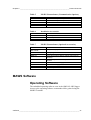
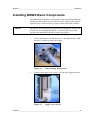
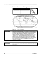
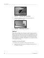
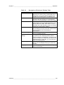
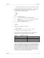
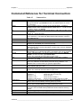
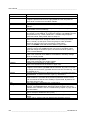
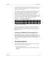
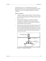
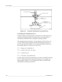
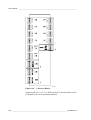
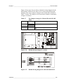
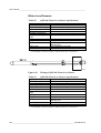
Connect cables to the connectors on the upper base and tighten
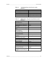
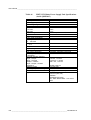
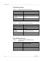
the screw nuts. For connector description, see Table 11 below.
Table 11
Connector
(A) T+RH
(B) Wind
(C) Solar
(D)
(E)
(F)
3.
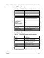
Default Upper Base Connectors
Sensor/Device
QMH101
QMW101
Power supply (solar panel or mains power)
QMR101 or QMR102
QMS101 or QMS102
QMN101
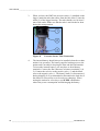
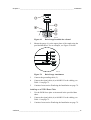
Finally, lower the protection cover on the upper base to shield
the connectors.
Installing Pressure Sensor
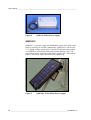
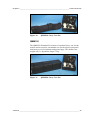
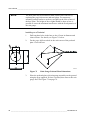
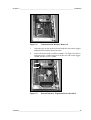
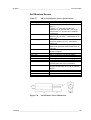
The PMT16A Pressure Sensor is located on the CPU board of the
logger, see Figure 64 on page 73. Normally, it is factory installed on
the logger board. If necessary, it can be accessed by removing the
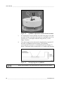
cover of the logger. The sensor is connected directly into the
connector on the board and is fixed on it by one screw.
CAUTION
When handling the sensor, take care not to bent any components on
the transducer board.
CAUTION
Beware of electrostatic discharge when touching objects inside the
logger housing.
CAUTION
Make sure that the vent tube of the pressure sensor is not blocked or
bent during transportation.
72 ___________________________________________________________________ M210243en-A