1
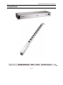
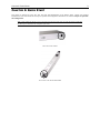
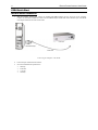
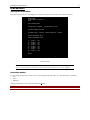
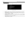
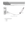
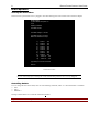
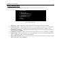
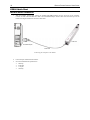
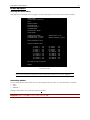
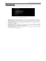
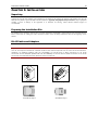
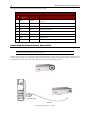
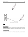
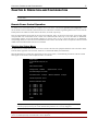
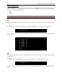
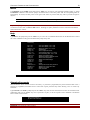
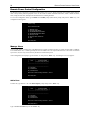
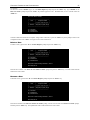
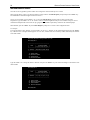
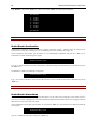
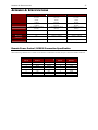
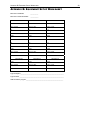
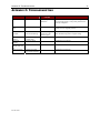
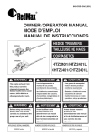
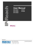
`
User Manual
PCR8
PCS12
PCS20
This page intentionally left blank
User Manual
PCR8
PCS12
PCS20
Copyright © 2003 Raritan Computer, Inc.
RPC-0B-E
August 2003
255-30-3150
Raritan Computer Inc.
400 Cottontail Lane
Somerset, NJ 08873
USA
Tel. 1-732-764-8886
Fax. 1-732-764-8887
E-mail: [email protected]
http://www.raritan.com
Raritan Computer Europe, B.V.
Eglantierbaan 16
2908 LV Capelle aan den IJssel
The Netherlands
Tel. 31-10-284-4040
Fax. 31-10-284-4049
E-mail: [email protected]
http://www.raritan.com
Raritan Computer Japan, Inc.
Kuga Building 7F
11-6, Kuramae 4-chome
Taitoo-ku, Tokyo 111-0051, Japan
Tel. 81-3-5833-6360
Fax. 81-3-5833-6336
E-mail: [email protected]
http://www.raritan.co.jp
Raritan Computer Taiwan, Inc.
5F, 121, Lane 235,
Pao-Chiao Rd., Hsin Tien
Taipei Hsien, Taiwan, ROC
Tel. 886-2-8919-1333
Fax. 886-2-8919-1338
E-mail: [email protected]
http://www.raritan.com.tw
This page intentionally left blank.
COPYRIGHT AND TRADEMARK INFORMATION
This document contains proprietary information that is protected by copyright. All rights reserved. No part of this document may be photocopied,
reproduced, or translated into another language without express prior written consent of Raritan Computer, Inc.
© Copyright 2003 Raritan Computer, Inc., Remote Power Control™, Paragon®, Reach®, Dominion™, Powerboard™ are trademarks of Raritan
Computer, Inc. All rights reserved. Java® is a registered trademark of Sun Microsystems, Inc. Internet Explorer® is a registered trademark of
Microsoft Corporation. Netscape® and Netscape Navigator® are registered trademarks of Netscape Communication Corporation. Other
trademarks or registered trademarks are the property of their respective holders.
Contact the Raritan Technical Support Team at (732) 764-8886 for assistance or email [email protected]
Ask for Technical Support – Monday through Friday, 8:00am to 5:00pm, EST.
This page intentionally left blank.
TABLE OF CONTENTS
i
TABLE OF CONTENTS
CHAPTER 1: INTRODUCTION ...........................................................................1
PRODUCT FEATURES .................................................................................................................................1
PACKAGE CONTENTS.................................................................................................................................1
PRODUCT PHOTOS ....................................................................................................................................2
CHAPTER 2: QUICK START .............................................................................3
PCR8 QUICK START .................................................................................................................................4
EIA-232 Serial Connection .............................................................................................................................. 4
PCR8 Operation.............................................................................................................................................. 5
Viewing the Status Menu _______________________________________________________________________ 5
Controlling Outlets_____________________________________________________________________________ 5
PCR8 Configuration ........................................................................................................................................ 6
PCS12 QUICK START ...............................................................................................................................7
EIA-232 Serial Connection .............................................................................................................................. 7
PCS12 Operation ............................................................................................................................................ 8
Viewing the Status Menu _______________________________________________________________________ 8
Controlling Outlets_____________________________________________________________________________ 8
PCS12 Configuration....................................................................................................................................... 9
PCS20 QUICK START .............................................................................................................................10
EIA-232 Serial Connection ............................................................................................................................ 10
PCS20 Operation .......................................................................................................................................... 11
Viewing the Status Menu ______________________________________________________________________ 11
Controlling Outlets____________________________________________________________________________ 11
PCS20 Configuration..................................................................................................................................... 12
CHAPTER 3: INSTALLATION ..........................................................................13
UNPACKING.............................................................................................................................................13
PREPARING THE INSTALLATION SITE .........................................................................................................13
RJ-45 CABLES AND ADAPTERS ................................................................................................................13
CONNECTING THE REMOTE POWER CONTROL UNIT ..................................................................................14
Power ............................................................................................................................................................ 15
Power On/Off State ....................................................................................................................................... 15
Power Up Sequence ..................................................................................................................................... 15
Circuit Breaker .............................................................................................................................................. 16
Serial Connection .......................................................................................................................................... 16
The EIA-232 Serial Connection__________________________________________________________________ 16
CHAPTER 4: OPERATION AND CONFIGURATION ................................................17
REMOTE POWER CONTROL OPERATION ...................................................................................................17
Viewing the Status Menu............................................................................................................................... 17
Controlling Outlets......................................................................................................................................... 18
On ________________________________________________________________________________________ 18
Off ________________________________________________________________________________________ 18
Reboot_____________________________________________________________________________________ 19
Help............................................................................................................................................................... 19
Changing Passwords .................................................................................................................................... 19
ii
TABLE OF CONTENTS
REMOTE POWER CONTROL CONFIGURATION ............................................................................................20
Manage Users ............................................................................................................................................... 20
Add a User _________________________________________________________________________________ 20
Delete a User _______________________________________________________________________________ 21
Rename a User ______________________________________________________________________________ 21
Add and Remove Outlets ______________________________________________________________________ 22
Change Outlet Names................................................................................................................................... 23
Enable/Disable Confirmation......................................................................................................................... 24
Enable/Disable Status Menu ......................................................................................................................... 24
Change Unit ID.............................................................................................................................................. 25
Change Overload Audible Alarm Threshold .................................................................................................. 25
APPENDIX A: SPECIFICATIONS ......................................................................27
REMOTE POWER CONTROL / SCS232 CONNECTION SPECIFICATION .........................................................27
APPENDIX B: EQUIPMENT SETUP WORKSHEET ................................................29
APPENDIX C: TROUBLESHOOTING..................................................................31
Safety Instructions
1.
2.
3.
4.
5.
This unit is intended for indoor use only.
Do not install near water or expose this unit to moisture.
To prevent heat buildup, do not coil the power cord when in use.
Do not use extension cords.
Do not attempt to make any internal changes to the power source. Do not attempt to modify any portion or component
of a Remote Power Control unit unless specifically directed to. Raritan must perform any internal operations.
6. High-voltage surges and spikes can damage this equipment. To protect from such power surges and spikes, this unit
must have a good earth ground. There is an earth ground connection next to the circuit breaker.
7. Before removing or replacing any cables or power cords, power off the Remote Power Control unit. Communication to
the unit will be disrupted while power is off.
8. Do not exceed the AC current rating for the selected model. (Please refer to Appendix A: Specifications for further
information).
9. Although the power switch is turned OFF, the unit is not totally isolated from the power supply. In order to be
absolutely removed from the power supply, the power cord must be unplugged from the unit.
10. For PERMANENTLY CONNECTED EQUIPMENT, a readily accessible disconnect device shall be incorporated in
the fixed wiring. For PLUGGABLE EQUIPMENT, the socket-outlet shall be installed near the equipment and easily
accessible.
This page intentionally left blank.
CHAPTER 1: INTRODUCTION
1
CHAPTER 1: INTRODUCTION
The Raritan Remote Power Control unit is a full-featured AC power management solution that provides an easy way to control
power of remote equipment. It provides system administrators with the capability to securely monitor and control power to data
center devices from any location via web browser, serial, or out-of-band access. From the office or from anywhere, the Remote
Power Control unit will power on, power off, or reboot remote equipment, as well as monitor current, voltage, power, and
temperature.
The Remote Power Control unit offers the ability to recover systems remotely in the event of system failure and/or system
lockup. It eliminates the need to perform manual intervention or dispatch field personnel, reduces downtime and mean time to
repair, and increases productivity.
There are three Remote Power Control models; model PCR8, a rack-mountable eight outlet model that operates at 115VAC, 15
Amps; model PCS12, a vertical-mount twelve-outlet model that operates at 115VAC, 20 amps; and model PCS20, a verticalmount twenty-outlet model that also operates at 115VAC, 20 amps.
115 VAC, 50/60 HZ, 15 AMP
PCR8
Eight outlets, 1U rack mount, and an EIA-232 connection
PCS12
PCS20
Twelve outlets, “zero-U” vertical mount, and an EIA-232 connection
Twenty outlets, “zero-U” vertical mount, and an EIA-232 connection
115 VAC, 50/60 HZ, 20 AMP
Product Features
•
•
•
•
•
•
•
•
Total integration with Raritan’s Paragon, Reach, and Dominion solutions
True RMS current monitoring with Overload Audible Alarm and indicator LED
Outlet status retention during power loss
Individual or collective control of outlets
Programmable unit ID and outlet names
Voltage and temperature monitoring
1U or “zero-U” form factor
15 or 20 Amp Power Rating
Package Contents
The complete Remote Power Control unit package includes:
•
•
•
•
•
(1) Remote Power Control unit (PCR8, PCS12, or PCS20)
(1) User Manual and/or User Manual CD ROM
(1) Cat5e Cable
(1) DB-9 (9 pin) female PC com port adapter (part #APCSDB9F)
(1) DB-25 (25 pin) male PC com port adapter (part #APCSDB25M)
2
REMOTE POWER CONTROL USER GUIDE
Product Photos
PCR8
PCS12
PCS20
CHAPTER 2: QUICK START
3
CHAPTER 2: QUICK START
This chapter is designed for users who want fast setup and familiarization of the Remote Power Control unit. Detailed
information on each of the functions and steps of operation and configuration outlined here are found in Chapter 4: Operation
and Configuration.
Note: On the PCR8, the RJ-45 port is located on the front panel of the unit. On both the PCS12 and PCS20,
the RJ-45 port is located on the end panels of the units.
RJ-45 Port on the PCR8
RJ-45 Port on the PCS12 and PCS20
4
REMOTE POWER CONTROL USER GUIDE
PCR8 Quick Start
EIA-232 Serial Connection
1.
With the computer powered ON, connect the included APCSDB9F adapter into the serial port of the computer.
Connect one end of the included Cat5 cable to the APCSDB9F adapter and the other end to the RJ-45 port on the PCR8
unit. Plug the PCR8 into the nearest wall outlet.
PCR8 Unit
APCSDB9F Adapter
Local PC
Cat5e Cable
Connecting the Computer to the PCR8
2.
3.
Load serial port communications software.
Set serial communications parameters to:
•
•
•
•
9600 bps
8 data bits
1 stop bit
No Parity
CHAPTER 2: QUICK START
5
PCR8 Operation
Viewing the Status Menu
The PCR8 unit powers ON once it is plugged in. The Status menu appears on the monitor of the connected computer:
Raritan PCR8
(C) 2003 Raritan Computer, Inc.
F2.07
Unit ID: Raritan PCR8
Average Power: 36 Watts
Apparent Power: 62 VA
True RMS Voltage: 116.4 Volts
True RMS Current: 0.5 Amps
Maximum Detected: 0.5 Amps
Internal Temperature: 28.0 C
Outlet Circuit Breaker: Good
1) . . . Outlet 1
2) . . . Outlet 2
3) . . . Outlet 3
4) . . . Outlet 4
5) . . . Outlet 5
6) . . . Outlet 6
7) . . . Outlet 7
8) . . . Outlet 8
: Off
: Off
: Off
: Off
: Off
: Off
: Off
: Off
PCR8>
PCR8 Status Menu
Note: If the Status menu does not appear, ensure that the correct cables and adapters are being used and that
they are connected properly, and verify the serial communication parameters are correctly configured.
Controlling Outlets
To set or change the status of the outlets, enter one of the following commands, where “n” is the outlet number to command:
•
ON n
•
OFF n
•
REBOOT n
Entering an outlet number of “0” sends the command to all outlets.
Important! Reboot works only on those outlets that are “On.”
6
REMOTE POWER CONTROL USER GUIDE
PCR8 Configuration
At the PCR8> prompt, type CONFIG and press the <Enter> key. The Configuration menu appears:
PCR8> CONFIG
1)...Manage Users
2)...Change Outlet Name
3)...Enable/Disable Confirmation
4)...Enable/Disable Status Menu
5)...Change Unit ID
6)...Change Alarm Threshold
X)...Exit
Enter Request:
PCR8 Configuration Menu
1.
2.
3.
4.
5.
6.
Manage Users – Manage Users allows an Administrator to add or delete users and assign control of selected outlets.
Change Outlet Name – Change Outlet Name allows a user to personalize each outlet for easy identification.
Maximum field length is ten (10) alphanumeric characters; default Outlet Names are Outlet 1, Outlet 2, and so on.
Enable/Disable Confirmation – Enable/Disable Confirmation prompts a user for a Yes/No response before a
command is executed; default setting is Disabled.
Enable/Disable Status Menu – Enable/Disable Status menu toggles the status menu on/off; default setting is Enabled.
Change Unit ID – Change Unit ID allows a user to name the Remote Power Control unit. Maximum field length is
sixteen (16) alphanumeric characters; default unit ID is PCR8.
Change Alarm Threshold – Change Alarm Threshold allows a user to set a threshold for the volume of the Overload
Audible Alarm; default setting is 12.0 Amps.
CHAPTER 2: QUICK START
7
PCS12 Quick Start
EIA-232 Serial Connection
1.
With the computer powered ON, connect the included APCSDB9F adapter into the serial port of the computer.
Connect one end of the included Cat5 cable to the APCSDB9F adapter and the other end to the RJ-45 port on the
PCS12 unit. Plug the PCS12 into the nearest wall outlet.
PCS12 Unit
APCSDB9F Adapter
Local PC
Cat5e Cable
Connecting the Computer to the PCS12
2.
3.
Load serial port communications software.
Set serial communications parameters to:
•
•
•
•
9600 bps
8 data bits
1 stop bit
No Parity
8
REMOTE POWER CONTROL USER GUIDE
PCS12 Operation
Viewing the Status Menu
The PCS12 unit is powered ON once it is plugged in. The Status menu appears on the monitor of the connected computer:
Raritan PCS12
(C) 2003 Raritan Computer, Inc.
F1.01
Option(s) Installed:
True RMS Current
True RMS Voltage: 116 Volts
True RMS Current: 0.0 Amps
Maximum Detected: 0.0 Amps
1) . . . Outlet 1 : Off
2) . . . Outlet 2 : Off
3) . . . Outlet 3 : Off
4) . . . Outlet 4 : Off
5) . . . Outlet 5 : Off
6) . . . Outlet 6 : Off
7) . . . Outlet 7 : Off
8) . . . Outlet 8 : Off
9) . . . Outlet 9 : Off
10) . . . Outlet 10 : Off
11) . . . Outlet 11 : Off
12) . . . Outlet 12 : Off
Type “Help” for a list of commands
PCS12>
PCS12 Status Menu
Note: If the Status menu does not appear, ensure that the correct cables and adapters are being used and that
they are connected properly, and verify the serial communication parameters are correctly configured.
Controlling Outlets
To set or change the status of the outlets, enter one of the following commands, where “n” is the outlet number to command:
•
ON n
•
OFF n
•
REBOOT n
Entering an outlet number of “0” sends the command to all outlets.
Important! Reboot works only on those outlets that are “On.”
CHAPTER 2: QUICK START
9
PCS12 Configuration
At the PCS12> prompt, type CONFIG and press the <Enter> key. The Configuration menu appears:
PCS12> CONFIG
1)...Manage Users
2)...Change Outlet Name
3)...Enable/Disable Confirmation
4)...Enable/Disable Status Menu
5)...Change Unit ID
6)...Change Alarm Threshold
X)...Exit
Enter Request:
PCS12 Configuration Menu
1.
2.
3.
4.
5.
6.
Manage Users – Manage Users allows a user to add or delete users, and assign control of selected outlets.
Change Outlet Name – Change Outlet Name allows a user to personalize each outlet for easy identification.
Maximum field length is ten (10) alphanumeric characters; default Outlet Names are Outlet 1, Outlet 2, and so on.
Enable/Disable Confirmation – Enable/Disable Confirmation prompts a user for a Yes/No response when changes are
made; default setting is disabled.
Enable/Disable Status Menu – Enable/Disable Status menu toggles the status menu on/off; default setting is enabled.
Change Unit ID – Change Unit ID allows a user to name the Remote Power Control unit. Maximum field length is
sixteen (16) alphanumeric characters; default unit ID is PCS12.
Change Alarm Threshold – Change Alarm Threshold allows a user to set a threshold for the volume of the Overload
Audible Alarm; default setting is 16.0 Amps.
10
REMOTE POWER CONTROL USER GUIDE
PCS20 Quick Start
EIA-232 Serial Connection
1.
With the computer powered ON, connect the included APCSDB9F adapter into the serial port of the computer.
Connect one end of the included Cat5 cable to the APCSDB9F adapter and the other end to the RJ-45 port on the
PCS20 unit. Plug the PCS20 into the nearest wall outlet.
PCS20 Unit
APCSDB9F Adapter
Local PC
Cat5e Cable
Connecting the Computer to the PCS20
2.
3.
Load serial port communications software.
Set serial communications parameters to:
•
•
•
•
9600 bps
8 data bits
1 stop bit
No Parity
CHAPTER 2: QUICK START
11
PCS20 Operation
Viewing the Status Menu
The PCS20 unit is powered ON once it is plugged in. The Status menu appears on the monitor of the connected computer:
Raritan PCS20
(C) 2003 Raritan Computer, Inc.
F1.01
Option(s) Installed:
True RMS Current
Internal Temperature
True RMS Voltage
Enter user name: Raritan
Unit ID: RPS20
Average Power: 0 Watts
True RMS Voltage: 110.6 Volts
True RMS Current: 1.5 Amps
Apparent Power: 177 VA
Maximum Detected: 8.4 Amps
Internal Temperature: 26.5 C
Outlet Circuit Breaker: Good
1)...Outlet 1
3)...Outlet 3
5)...Outlet 5
7)...Outlet 7
9)...Outlet 9
11)...Outlet 11
13)...Outlet 13
15)...Outlet 15
17)...Outlet 17
19)...Outlet 19
: Off
: Off
: Off
: Off
: Off
: Off
: Off
: Off
: Off
: Off
2)...Outlet 2
4)...Outlet 4
6)...Outlet 6
8)...Outlet 8
10)...Outlet 10
12)...Outlet 12
14)...Outlet 14
16)...Outlet 16
18)...Outlet 18
20)...Outlet 20
: Off
: Off
: Off
: Off
: Off
: Off
: Off
: Off
: Off
: Off
Type "Help" for a list of commands
PCS20>
PCS20 Status Menu
Note: If the Status menu does not appear, ensure that the correct cables and adapters are being used and that
they are connected properly, and verify the serial communication parameters are correctly configured.
Controlling Outlets
To set or change the status of the outlets, enter one of the following commands, where “n” is the outlet number to command:
•
ON n
•
OFF n
•
REBOOT n
Entering an outlet number of “0” sends the command to all outlets.
Important! Reboot works only on those outlets that are “On.”
12
REMOTE POWER CONTROL USER GUIDE
PCS20 Configuration
At the PCS20> prompt, type CONFIG and press the <Enter> key. The Configuration menu appears:
PCR20> CONFIG
1)...Manage Users
2)...Change Outlet Name
3)...Enable/Disable Confirmation
4)...Enable/Disable Status Menu
5)...Change Unit ID
6)...Change Alarm Threshold
X)...Exit
Enter Request:
PCS20 Configuration Menu
1.
2.
3.
4.
5.
6.
Manage Users – Manage Users allows an Administrator to add or delete users, and assign control of selected outlets.
Change Outlet Name – Change Outlet Name allows a user to personalize each outlet for easy identification.
Maximum field length is ten (10) alphanumeric characters; default Outlet Names are Outlet 1, Outlet 2, and so on.
Enable/Disable Confirmation – Enable/Disable Confirmation prompts a user for a Yes/No response when changes are
made; default setting is disabled.
Enable/Disable Status Menu – Enable/Disable Status menu toggles the status menu on/off; default setting is enabled.
Change Unit ID – Change Unit ID allows a user to name the Remote Power Control unit. Maximum field length is
sixteen (16) alphanumeric characters; default unit ID is PCS20.
Change Alarm Threshold – Change Alarm Threshold allows a user to set a threshold for the volume of the Overload
Audible Alarm; default setting is 16.0 Amps.
CHAPTER 3: INSTALLATION
13
CHAPTER 3: INSTALLATION
Unpacking
Compare the unit and serial number of the equipment to the number on the packing slip located on the outside of the box and
make sure they match. Log the information on the worksheet in Appendix B: Equipment Setup Worksheet. Inspect equipment
carefully. If there is damage to the equipment or if materials are missing, contact Raritan technical support at
732-764-8886.
Preparing the Installation Site
The installation area should be clean and free of extreme temperatures and humidity. Allow sufficient space around the Remote
Power Control unit for cabling and outlet connections. Please review the Safety Instructions listed in the beginning of this
manual.
RJ-45 Cables and Adapters
Important! All Remote Power Control models have an RJ-45 port for connecting to a local EIA-232 device
such as a computer terminal or external modem. Most serial computers do not have RJ-45 connections,
therefore, an adapter (Raritan Part No. APCSDB9F) to convert from a DB-9 connector to an RJ-45
connector and an adapter (Raritan Part No. APCSDB25M) to convert from a DB-25 connector to an RJ-45
connector are included with each Remote Power Control unit.
RJ-45 outlet
RJ-45 plug
APCSDB25M Adapter
APCSDB9F Adapter
14
REMOTE POWER CONTROL USER GUIDE
The Power Control Units RJ-45 control port uses the following signals:
EIA-232 RJ-45 PIN/SIGNAL DEFINITION
PIN
EIA-232
SIGNAL
DIRECTION
DESCRIPTION
1
DTR
Output
+10V when activated by DCD; toggles upon logout for modem
disconnect.
2
GND
----
Signal Ground
3
RTS
Output
+10V when powered is applied; not used as a handshake line
4
TX
Output
Transmit Data (data out)
5
RX
Input
Receive Data (data in)
6
N/C
N/C
No Connection
7
GND
----
Signal Ground
8
DCD
Input
DCD into the Remote Power Control unit
Connecting the Remote Power Control Unit
Note: On the PCR8, the RJ-45 port is located on the front panel of the unit. On both the PCS12 and PCS20,
the RJ-45 port is located on the end panels of the units.
With the computer powered ON, connect the included APCSDB9F adapter into the serial port of the computer. Connect one end
of the included Cat5 cable to the APCSDB9F adapter and the other end to the RJ-45 port on the Remote Power Control unit. Plug
the Remote Power Control unit into the nearest wall outlet. The unit will automatically power ON.
PCR8 RJ-45 Port
PCR8 Unit
APCSDB9F Adapter
Local PC
Cat5e Cable
Connecting the Computer to a PCR8
CHAPTER 3: INSTALLATION
15
PCS12 and PCS20 RJ-45 Port
PCS12 Unit or
PCS20 Unit
APCSDB9F Adapter
Local PC
Cat5e Cable
Connecting the Computer to a PCS12 or a PCS20
Power
As soon as the Remote Power Control unit is plugged into a wall outlet, it powers ON. A green LED on the front panel is
illuminated. If disconnected from a power source, the unit’s LED is not lit, and devices connected to the unit are not receiving
power.
Power On/Off State
Each outlet on the Remote Power Control unit is individually controlled by an internal relay. Upon initialization of power, the
status of each outlet will return to the state it was in prior to losing power. For example, if Outlet 1 and Outlet 2 are On and
power is removed from the Remote Power Control, when power is restored to the unit, the status of Outlet 1 and Outlet 2 will
return to On.
Power Up Sequence
In order to minimize power surges, the Remote Power Control unit sequences power to each outlet in the On state in 0.3-second
intervals. When power is applied to the Remote Power Control unit, the initialization sequence requires a delay of 10 seconds
before power is available at the service outlets. Following the 10-second delay, the Remote Power Control unit sequences power
to each outlet that is turned On. If the REBOOT command is entered for all outlets of the unit, the Remote Power Control unit
sequences power to each outlet turned On in 0.1-second intervals.
16
REMOTE POWER CONTROL USER GUIDE
Circuit Breaker
In the case of power overload, the circuit breaker automatically trips. Determine the cause of the tripped circuit breaker, correct
the problem, and reset the circuit breaker by depressing the circuit breaker button. This button is located on the back panel of the
PCR8 unit, and on the front panels of the PCS12 and PCS20 units. Power to the unit (electronics, EIA-232 port, etc.) does not go
through the circuit breaker. This circuit is protected by a ¼ amp hardwired fuse. If an overload condition occurs, the Remote
Power Control unit status menu is still accessible.
Circuit Breaker status is reflected on the Status menu. If the breaker is operating properly, the Outlet Circuit Breaker: status
will read “Good.” When there is a problem with the circuit breaker, or if it is tripped, its status will read “Fault.”
Serial Connection
The EIA-232 Serial Connection
Once the Remote Power Control unit is connected to the local computer, load serial port communications software and configure
host terminal’s serial communications parameters to match the Remote Power Control unit:
•
•
•
•
9600 bps
8 data bits
1 stop bit
No Parity
CHAPTER 4: OPERATION AND CONFIGURATION
17
CHAPTER 4: OPERATION AND CONFIGURATION
Note: Please type all commands carefully. Inaccurate entries can cause error messages and the return to the
previous menu.
Remote Power Control Operation
The PCR8, PCS12, and PCS20 models are configured in the same manner. This detailed Operation and Configuration section
will use PCR8 screens for illustration and assume that the Confirmation is enabled. Programming differences for the PCS12 and
PCS20 pertain to the number of outlets shown in the menus (12 and 20, respectively).
There are eight numbered green LEDs on the front of the PCR8 unit, twelve on the PCS12, and twenty on the PCS20, which
correspond with each of the Remote Power Control unit’s numbered outlets. When any or all of the LEDs are illuminated,
corresponding outlet(s) are ON and attached equipment is receiving power. If any or all of the LEDs are not illuminated,
corresponding outlet(s) are OFF. The PCS12 and PCS20 units also have a red LED that works in conjunction with the Overload
Audible Alarm and will illuminate if the unit is overloaded.
Viewing the Status Menu
The Remote Power Control Status menu allows users to monitor and control the equipment attached to each of the unit’s outlets.
From this menu, equipment can be turned on, turned off, or rebooted individually or simultaneously.
When the Remote Power Control unit is plugged into an active power source, it is automatically powered ON. The unit’s Status
menu appears on the monitor of the computer to which it is connected.
Raritan PCR8
(C) 2003 Raritan Computer, Inc.
F2.07
Unit ID: Raritan PCR8
Average Power: 36 Watts
Apparent Power: 62 VA
True RMS Voltage: 116.4 Volts
True RMS Current: 0.5 Amps
Maximum Detected: 0.5 Amps
Internal Temperature: 28.0 C
Outlet Circuit Breaker: Good
1) . . . Outlet 1
2) . . . Outlet 2
3) . . . Outlet 3
4) . . . Outlet 4
5) . . . Outlet 5
6) . . . Outlet 6
7) . . . Outlet 7
8) . . . Outlet 8
: Off
: Off
: Off
: Off
: Off
: Off
: Off
: Off
PCR8>
Note: If the Status menu fails to appear, ensure the correct cables and adapters are being used and they are
connected properly and verify the serial communication parameters are correctly configured.
Important! To access the Status menu from the Configuration menu or any sub-menu, press the <Enter> key
at the command prompt until the Status menu appears.
18
REMOTE POWER CONTROL USER GUIDE
Controlling Outlets
Any of the commands on the Help menu shown in this and the next section, Help, can be executed from the Status menu. The
primary commands to set or change the status of an outlet are ON, OFF, and REBOOT. Enter one of the following commands,
where “n” is the outlet number to command:
•
ON n
•
OFF n
•
REBOOT n
Important! Enter an outlet number of zero (“0”) to send the command to all outlets.
On
Type ON n at the PCR8> prompt and press the <Enter> key to turn Outlet “n” On. Confirm the command, and the outlet powers
ON.
For Example:
To power ON Outlet 3, type ON 3 at the PCR8> prompt and press the <Enter> key. A confirmation screen will appear:
Turn On Outlet 3 (Y/N)?
Type the letter <Y> to confirm the request and Outlet 3 will be turned On. The status of Outlet 3 will change to On in the Status
menu, as shown:
1) . . . Outlet 1
2) . . . Outlet 2
3) . . . Outlet 3
4) . . . Outlet 4
5) . . . Outlet 5
6) . . . Outlet 6
7) . . . Outlet 7
8) . . . Outlet 8
: Off
: Off
: On
: Off
: Off
: Off
: Off
: Off
PCR8>
Off
Type OFF n at the PCR8> prompt and press the <Enter> key to turn Outlet “n” Off. Confirm the command, and the outlet will
be turned Off.
For Example:
To power OFF Outlet 3, type OFF 3 at the prompt and press the <Enter> key. A confirmation screen will appear:
Turn Off Outlet 3 (Y/N)?
Type the letter <Y> to confirm the request and Outlet 3 will be turned Off. The status of Outlet 3 will change to Off in the Status
menu.
CHAPTER 4: OPERATION AND CONFIGURATION
19
Reboot
Type REBOOT n at the PCR8> prompt and press the <Enter> key to reboot or reset equipment attached to Outlet “n.” When
the REBOOT command is sent from the prompt, the Remote Power Control unit powers OFF the corresponding outlet for
approximately 10 seconds, and then powers it ON again. If all outlets are powered OFF, they will be powered ON again in
sequence.
Note: This command works only on outlets that were “ON” prior to executing the Reboot command.
Important! Typing ON 0 (zero), OFF 0, or REBOOT 0 at the command prompt causes the Remote Power
Control to turn ON, OFF, or REBOOT ALL outlets. Entering a 0 (zero) indicates that the command should be
executed for ALL outlets.
Help
Type HELP at the prompt and press the <Enter> key to view a list of commands and functions for the Remote Power Control
unit. These commands can be typed at the Status menu prompt at any time:
PCR8>help
On n <cr>
Off n <cr>
Reboot n <cr>
Status <cr>
Config <cr>
Lock n <cr>
Unlock n <cr>
Current <cr>
Clear <cr>
Temp <cr>
Voltage <cr>
Logout <cr>
Logoff <cr>
Exit <cr>
Password <cr>
Whoami <cr>
Unitid <cr>
Help <cr>
--Turn on an Outlet, n=0,1...8,all
--Turn off an Outlet, n=0,1...8,all
--Reboot an Outlet, n=0,1...8,all
--PCR8 Status
--Enter configuration mode
--Locks Outlet(s) state, n=0,1...8,all
--Unlock Outlet(s) state, n=0,1...8,all
--Display True RMS Current
--Reset the maximum detected current
--Read current temperature
--Display True RMS Voltage
--Logoff
--Logoff
--Logoff
--Changes the current user password
--Displays the current user name
--Displays the unit ID
--This Command
Note: <cr> indicates a carriage return or <Enter>
Changing Passwords
When the Remote Power Control unit leaves the factory, no password is programmed; the password field is blank. Once a
password is programmed, the Remote Power Control unit requires password entry before allowing a user to execute any
commands.
Type Password at the PCR8> prompt and press the <Enter> key. Enter the new Password, then re-enter the new Password for
confirmation, and press the <Enter> key. Once a password is in place, it will be required to issue commands to the Remote
Power Control unit in the future.
Enter new Password>*****
Re-Enter new Password>
Important! Passwords are case sensitive.
20
REMOTE POWER CONTROL USER GUIDE
Remote Power Control Configuration
The Remote Power Control unit’s Configuration menu allows users to set or change passwords and customize outlet names in
order to easily identify attached equipment. Users can also enable or disable command confirmation, enable or disable the Status
menu, change the unit name, and adjust the threshold level for sounding the alarm.
To access the Configuration menu, type CONFIG at the PCR8> prompt (Status menu prompt) and press the <Enter> key. The
Configuration menu appears:
PCR8>config
Unit ID: Raritan PCR8
1)...Manage Users
2)...Change Outlet Name
3)...Enable/Disable Confirmation
4)...Enable/Disable Status Menu
5)...Change Unit ID
6)...Change Alarm Threshold
X)...Exit
Enter Request>
Manage Users
Users can add, delete, or rename users of the Remote Power Control unit and assign users to control selected outlets. In addition
to the Administrator user, or Admin (generally the first user added to the User list), the Remote Power Control unit can maintain
up to twelve (12) users. Any of the users may be deleted or renamed at any time.
At the Configuration menu prompt, type the number <1> and press the <Enter> key. The Manage Users screen appears:
---------------------------------------------------|
User
|
Assigned Outlets |
|
|1|2|3|4|5|6|7|8|
------------------------------------------------------------------------------------------------------A)...Add User
D)...Delete User
R)...Rename User
Enter user number to assign Outlets, A, D or R.
Enter Request>
Add a User
To add a user, type the letter <A> at the Enter Request: prompt and press the <Enter> key.
---------------------------------------------------|
User
|
Assigned Outlets
|
|
|1|2|3|4|5|6|7|8 |
------------------------------------------------------------------------------------------------------A)...Add User
D)...Delete User
R)...Rename User
Enter user number to assign Outlets, A, D or R.
Enter Request> A
Type in the new user name and press the <Enter> key.
CHAPTER 4: OPERATION AND CONFIGURATION
21
For Example:
The new user’s name is Raritan. Type <1> at the Enter Request: prompt and press the <Enter> key. Type <Raritan> at the
Enter User Name: prompt and press the <Enter> key. Raritan appears as User 1. Remember that, as User 1, Raritan is also the
Admin user:
Enter User Name> Raritan
-----------------------------------------------------|
User
|
Assigned Outlets
|
|
|1|2|3|4|5|6|7|8 |
-----------------------------------------------------1) Raritan | N |N |N | N | N |N | N | N|
-----------------------------------------------------A)...Add User
D)...Delete User
R)...Rename User
Continue to add users until the list is complete. Assign outlets at this time, or press the <Enter> key at the prompt to return to the
Configuration menu. Press <Enter> once again to return to the Status menu.
Delete a User
To Delete a user, type the letter <D> at the Enter Request: prompt and press the <Enter> key.
---------------------------------------------------|
User
|
Assigned Outlets
|
|
|1|2|3|4|5|6|7|8 |
---------------------------------------------------1) Raritan | N |N |N | N | N |N | N | N|
---------------------------------------------------A)...Add User
D)...Delete User
R)...Rename User
Enter user number to assign Outlets, A, D or R.
Enter Request: D
Enter the user’s number at the Enter the user number to delete: prompt and press the <Enter> key. The user will be removed
from the list of user names.
Rename a User
To Rename a user, type the letter <R> at the Enter Request: prompt and press the <Enter> key.
---------------------------------------------------|
User
|
Assigned Outlets
|
|
|1|2|3|4|5|6|7|8 |
---------------------------------------------------1) Raritan | N |N |N | N | N |N | N | N|
---------------------------------------------------A)...Add User
D)...Delete User
R)...Rename User
Enter user number to assign Outlets, A, D or R.
Enter Request: R
Enter the user number at the Enter user number to rename: prompt, enter the new user name at the Enter User Name: prompt,
and then press the <Enter> key. The updated name will be reflected in the list of user names.
22
REMOTE POWER CONTROL USER GUIDE
Add and Remove Outlets
Once the user list is populated, specific outlets can be assigned or removed from any user’s control.
When viewing the list of users, type the user number to assign outlets at the Enter Request: prompt and press the <Enter> key.
The Add/Remove outlets menu appears below the user list.
Once a user is specified, type the numbers <1> or <2> at the Enter Request: prompt to add or remove specific outlet
assignations. Type the numbers <3> or <4> to add or remove all outlet assignations with just one command. Assign or remove
command of multiple outlets to the same user by typing the outlet numbers separated by commas at the command prompt.
When finished, press the <Enter> key at the Enter Request: prompt twice to return to the Configuration menu.
For Example:
To assign all outlets to user “Raritan,” type the number <1> for user 1, “Raritan,” at the command prompt and press the <Enter>
key. “Raritan’s” list of assigned outlets appears. As a new user, “Raritan” does not control any outlets, indicated by the N below
each outlet number.
Enter User Number to Assign Outlets, A, D, R>
Enter Request: 1
-----------------------------------------------------|
User
|
Assigned Outlets
|
|
|1|2|3|4|5|6|7|8 |
-----------------------------------------------------1) Raritan | N |N |N | N | N |N | N | N|
-----------------------------------------------------1)
2)
3)
4)
Add an outlet
Remove an outlet
Add all outlets
Remove all outlets
Type the number <3> to assign all outlets to “Raritan” and press the <Enter> key. The status will change to read Y below each
outlet number:
Enter Request: 3
-----------------------------------------------------|
User
|
Assigned Outlets
|
|
|1|2|3|4|5|6|7|8 |
-----------------------------------------------------1) Raritan | Y | Y |Y | Y | Y |Y | Y | Y |
-----------------------------------------------------1)
2)
3)
4)
Add an outlet
Remove an outlet
Add all outlets
Remove all outlets
Enter Request:
CHAPTER 4: OPERATION AND CONFIGURATION
23
For Example:
If “Raritan” currently controls all outlets, to remove control of outlets 1, 4, 5, and 6, type <1, 4, 5, 6>at the Enter Request:
prompt and press the <Enter> key. The status of the assigned outlet will change from Y to N below the removed Outlets.
Enter Request>1
-----------------------------------------------------|
User
|
Assigned Outlets
|
|
|1|2|3|4|5|6|7|8 |
-----------------------------------------------------|
Raritan | N | Y | Y| N | N| N| Y | Y |
-----------------------------------------------------1)
2)
3)
4)
Add an outlet
Remove an outlet
Add all outlets
Remove all outlets
Press the <Enter> key at the Enter Request: prompt to return to the list of all users.
Change Outlet Names
Default outlet names are Outlet 1, Outlet 2, … through Outlet 8 on the PCR8, Outlet 1 through Outlet 12 on the PCS12, and
Outlet 1 through Outlet 20 on the PCS20. Change any outlet name for a customized configuration.
At the Configuration menu prompt, type the number <2> and press the <Enter> key. A list of all available outlets appears:
Enter Request> 2
1) . . . Outlet 1
2) . . . Outlet 2
3) . . . Outlet 3
4) . . . Outlet 4
5) . . . Outlet 5
6) . . . Outlet 6
7) . . . Outlet 7
8) . . . Outlet 8
Type the number of the outlet to be renamed at the Enter Request: prompt and press the <Enter> key. Confirm that the outlet
name is to be modified, enter the new outlet name at the Enter: prompt, and press the <Enter> key. The new outlet name
appears in the Outlet list.
Press the <Enter> key at the Enter Request: prompt to return to the Configuration menu.
For Example:
To change the name of Outlet 4 to “Router 4,” type the number <4> at the Enter Request: prompt and press the <Enter> key. A
confirmation screen appears:
Current Outlet: Outlet 4
Modify (Y/N)?
Type the letter <Y> to confirm and press the <Enter> key. An Enter prompt appears:
Enter:
24
REMOTE POWER CONTROL USER GUIDE
Type <Router 4> and press the <Enter> key. Outlet 4’s new name, “Router 4” is reflected in the Outlet list.
Enter Request>
1) . . . Outlet 1
2) . . . Outlet 2
3) . . . Outlet 3
4) . . . Router 4
5) . . . Outlet 5
6) . . . Outlet 6
7) . . . Outlet 7
8) . . . Outlet 8
Enter Request>
Important! Outlet names can contain up to 10 characters.
Enable/Disable Confirmation
Enable/Disable Confirmation activates or deactivates a backup method that requires confirmation before the Remote Power
Control unit will execute any commands (for a list of commands, please refer to the Help menu on page 19).
At the Configuration menu prompt, type the number <3> for Enable/Disable Confirmation and press the <Enter> key. If
confirmation is enabled, the following screen appears:
Disable Confirmation? (Y/N)
Type <Y> to disable confirmation, thereby avoiding future confirmation dialogs from the Remote Power Control unit, and press
the <Enter> key.
If confirmation is disabled, the following screen appears:
Enable Confirmation? (Y/N)
Type <Y> to enable confirmation, which will cause Remote Power Control to double-check all future commands, and press the
<Enter> key.
Important! The Default status for Enable/Disable Confirmation is ENABLED.
Enable/Disable Status Menu
The Enable/Disable Status menu feature toggles the Status menu on or off. If there is not enough space on the monitor or there is
no reason for or benefit of displaying the unit’s status information, disable the Status menu so that it does not appear. Enable the
Status menu to be kept aware of the unit’s status.
At the Configuration menu prompt, type the number <4> and press the <Enter> key. If the Status menu is enabled, the following
screen appears:
Disable Status Menu? (Y/N)
Type <Y> to disable the Status menu, and press the <Enter> key.
CHAPTER 4: OPERATION AND CONFIGURATION
25
If the Status menu is disabled, the following screen appears:
Enable Status Menu? (Y/N)
Type <Y> to enable the Status menu and press the <Enter> key.
Important! The Default status for Enable/Disable Status menu is ENABLED.
Change Unit ID
Change the Remote Power Control’s Unit ID to eliminate confusion, especially if working with multiple units. Giving the unit an
ID allows components to be located more easily in the event of technical problems or power outages, and also displays a
personalized name every time the Status menu appears on the monitor.
At the Configuration menu prompt, type the number <5> and press the <Enter> key. The current Unit ID appears:
Current Unit ID: PCR8
Modify (Y/N)?
Type <Y> to confirm that the Unit ID is to be modified and press the <Enter> key. At the Enter New Unit ID: prompt, type a
new ID and press the <Enter> key. The new Unit ID appears at the top of the menus that appear every time the unit is accessed.
Important! The Unit ID can contain up to sixteen characters.
Change Overload Audible Alarm Threshold
The Remote Power Control unit has a built-in Overload Audible Alarm that is triggered if the unit exceeds the electrical current
threshold. The range of the PCR8 should not exceed 15 Amps, and the ranges of the PCS12 and the PCS20 should not exceed 20
Amps. Please refer to Appendix A: Specifications for further information.
At the Configuration menu prompt, type <6> and press the <Enter> key. The current threshold value appears:
Buzzer alarm value : 16.0 Amps
Modify (Y/N)?
Type <Y> to confirm that the Overload value is to be modified and press the <Enter> key. At the Enter: prompt, type a new
threshold value and press the <Enter> key. The Remote Power Control unit accepts the new threshold automatically, and the
Configuration menu is displayed once again. The new threshold displays the next time a user modifies the threshold.
26
REMOTE POWER CONTROL USER GUIDE
APPENDIX A: SPECIFICATIONS
27
APPENDIX A: SPECIFICATIONS
POWER OUTLET
CIRCUIT BREAKER
EIA-232 SERIAL PORT
DIMENSIONS
SHIPPING WEIGHT
MOUNTING
(OPTIONAL)
WARRANTY
PCR8
8 each
115 VAC
60 Hz
15 Amp
125 VAC
15 Amp
8-pin modular connector
(RJ-45)
16.73w x 5.25”d x 1.72”h
PCS12
12 each
115 VAC
60 Hz
20 Amp
125 VAC
20 Amp
8 pin modular connector
(RJ-45)
1.75”w x 1.75”d x 56”h
PCS20
20 each
115 VAC
60 Hz
20 Amp
125 VAC
20 Amp
8 pin modular connector
(RJ-45)
1.75”w x 1.75”d x 65.76”h
5 lbs.
19”
8 lbs.
“zero-U” vertical
10 lbs.
“zero-U” vertical
Two years on parts and labor
Two years on parts and labor
Two years on parts and labor
Remote Power Control / SCS232 Connection Specification
When connecting a Remote Power Control unit to a Raritan ConsoleSwitch SCS232, these pin connections should be followed:
RPC UNIT
PIN #
EIA
SIGNAL
DIRECTION
SCS232 UNIT
PIN #
EIA
SIGNAL
1
2
3
4
5
6
7
8
DTR
GND
RTS
TX
RX
N/C
GND
DCD
Output
--Output
Output
Input
N/C
--Input
7
4
8
6
3
2
5
1
DSR
GND
CTS
RX
TX
DTR
SG
RTS
28
REMOTE POWER CONTROL USER GUIDE
APPENDIX B: EQUIPMENT SETUP WORKSHEET
29
APPENDIX B: EQUIPMENT SETUP WORKSHEET
RPC Series Unit Model
____________
RPC Series Unit Serial Number
____________
OUTLET 1
OUTLET 2
OUTLET3
MODEL
MODEL
MODEL
SERIAL NUMBER
SERIAL NUMBER
SERIAL NUMBER
USE
USE
USE
OUTLET 4
OUTLET 5
OUTLET 6
MODEL
MODEL
MODEL
SERIAL NUMBER
SERIAL NUMBER
SERIAL NUMBER
USE
USE
USE
OUTLET 7
OUTLET 8
OUTLET 9
MODEL
MODEL
MODEL
SERIAL NUMBER
SERIAL NUMBER
SERIAL NUMBER
USE
USE
USE
OUTLET 10
OUTLET 11
OUTLET 12
MODEL
MODEL
MODEL
SERIAL NUMBER
SERIAL NUMBER
SERIAL NUMBER
USE
USE
USE
Types of adapters_________________________________________________________________
Types of cables ___________________________________________________________________
Name of software program ________________________________________________________
30
REMOTE POWER CONTROL USER GUIDE
APPENDIX C: TROUBLESHOOTING
31
APPENDIX C: TROUBLESHOOTING
PROBLEM
SYMPTOM
POSSIBLE
CAUSE
SOLUTION
No menu visible
Blank Screen
Cables Adapters
Parameters
Ensure correct cables and adapters are being used and
are connected properly. Verify serial parameters are
correctly configured.
Password does not
work
Returns to prompt
Caps Lock
Password feature is case sensitive. Type password
exactly as it was originally entered.
Current alarm level
exceeded
Continuous buzzer
(current monitoring)
Reduce the load being drawn;
Reset the alarm trip point to a higher setting.
Can’t exit Outlet
Control
Device not
working
Need to download
manual from web
site
Forgot password
Returns to Outlet
Control menu
No power, dead
Unit is drawing
current above the
alarm trip point
Wrong command
255-30-3150
Type MENU
Call Raritan Tech Support
Visit www.raritan.com
Cannot access unit
past password prompt
Call Raritan Tech Support
32
REMOTE POWER CONTROL USER GUIDE