1
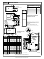
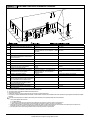
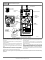
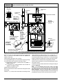
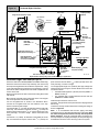
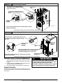
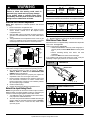
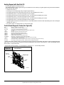
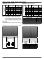
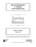
Upflow Installations Top Vent
Plastic Caps (2)
Yellow or black
On Some Models ONLY
INLET
EXHAUST
Figure 11
Coupling & Clamps
(Optional)
Single Pressure Switch
Vent Drain
& Clamps
VE
NT
IN
AIR FLOW
Dual Pressure Switch Detail
ON
OFF
Drain Tee
Relief Tube
Black Rubber 3/16
(4.8mm) ID
Drain Tube
Black Rubber
1/ (12.7mm) ID &
2
Clamps
Drain Tube
Corrugated
5/ (15.9mm) ID &
8
Clamps
Street Elbow
1/ CPVC
2
(Loose parts bag)
Drain Connector Black PVC
3/ (18.1mm) PVC X 1/ 4
2
(12.7mm) CPVC (Loose
parts bag)
Casing Grommet
Black Rubber
5/ (15.9mm) ID
8
(Loose parts bag)
Drain Line Vent Tee 3/4
(18.1mm) PVC or 1/2 (12.7mm)
CPVC (Field supplied)
Drain Tube Black Rubber 5/8 (15.9mm) ID &
Clamps, Cut length to fit (Loose parts bag)
Representative drawing only, some models may vary in appearance.
25−24−80
Upflow Installations Top Vent (See Figure 11)
Remove knockout from the side of the furnace casing where drain
tube will exit.
Glue the CPVC street elbow to the trap using appropriate cleaner
and solvent cement.
Install casing grommet [black rubber 5/8″ (15.9mm) ID grommet −
in loose parts bag].
The field supplied 3/4″ (18.1mm) PVC or 1/2″ (12.7mm) CPVC
drain line vent tee must vent outside the furnace cabinet (see
exploded view above).
Install the 1/2″ (12.7mm) CPVC street elbow on discharge of trap
Install the black PVC tube connector [ 3/4″ (18.1mm) PVC x 1/2″
(12.7mm) CPVC from loose parts bag] as shown in the illustration
above.
Cut the black drain tube [5/8″ (15.9mm) ID − in loose parts bag] to
length to fit between trap and tube connector through grommet.
Note: It is recommended that all PVC piping and fitting
connections be fit up and inspected before final cementing. Trap
must be primed before operation. Verify all condensate drain
connections are securely clamped. A coupling and clamps (in
loose part bag) may be installed as shown for future servicing of
the vent system.
Clamp both ends of the drain tube using clamps provided.
NOTE: “PVC” is used as a generic term. Pipe and fitting materials used must be acceptable to the local code officials having
jurisdiction.
19
440 01 1024 04
Specifications are subject to change without notice