1
AD-4403-FP
Explosion Protected Weighing
Indicator
ST Series
Weighing Indicator for Explosion
Protected Platform Scale
INSTRUCTION MANUAL
Read all information in this manual and the ST series manual for the platform carefully and be
fully knowledgeable about the unit before use. And after you read, keep this manual at hand so
that you can refer to it whenever necessary.
WM:PD4000002A
© 2000 A&D Company Ltd. All rights reserved.
No part of this publication may be reproduced, transmitted, transcribed, or translated into any
language in any form by any means without the written permission of A&D Company Ltd.
The contents of this manual and the specifications of the instrument covered by this manual are
subject to change for improvement without notice.
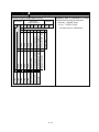
CONTENTS
APPENDIX ......................................................................................................................II
SAFETY TERMS USED IN THIS MANUAL...................................................................III
WARNING LABEL ........................................................................................................ IV
SAFETY PRECAUTIONS FOR INSTALLATION ........................................................... V
SAFETY PRECAUTIONS DURING OPERATION ......................................................... V
ABOUT THIS MANUAL ................................................................................................. V
1. INTRODUCTION .....................................................................................................1-1
1-1
1-2
1-3
1-4
1-5
FEATURES ....................................................................................................................... 1-1
FRONT PANEL ................................................................................................................. 1-2
DISPLAY ........................................................................................................................... 1-3
OPERATION KEYS........................................................................................................... 1-4
INSIDE THE CASE ........................................................................................................... 1-8
2. INSTALLATION .......................................................................................................2-1
2-1
2-2
2-3
2-4
PRECAUTIONS ................................................................................................................ 2-1
WIRING............................................................................................................................. 2-2
INSTALLING CONDUIT FITTINGS OPTION OP-10 - 14 ............................................. 2-5
INSTALLING WALL-MOUNTING FITTINGS ..................................................................... 2-6
3. OPERATION............................................................................................................3-1
3-1
3-2
3-3
3-4
3-5
TURNING THE POWER ON ............................................................................................. 3-1
BASIC OPERATION.......................................................................................................... 3-1
SETTING AND RECALLING SET POINTS ....................................................................... 3-2
RECALLING THROUGH CLEARING ACCUMULATION DATA......................................... 3-3
EDITING ACCUMULATION DATA..................................................................................... 3-4
4. CALIBRATION ........................................................................................................4-1
4-1
4-2
4-3
4-4
GENERAL ......................................................................................................................... 4-1
DIGITAL SPAN CALIBRATION.......................................................................................... 4-1
ACTUAL LOAD CALIBRATION ......................................................................................... 4-1
GRAVITY COMPENSATION ............................................................................................. 4-3
5. FUNCTION SETTINGS ...........................................................................................5-1
5-1
5-2
GENERAL ......................................................................................................................... 5-1
FUNCTION SETTINGS..................................................................................................... 5-2
6. WEIGHING ..............................................................................................................6-1
6-1
WEIGHING VALUE AND SET POINT ............................................................................... 6-1
6-2
WEIGHING MODES.......................................................................................................... 6-2
6-3
CALF-14=“1” WEIGHING MODE ...................................................................................... 6-4
6-4
CALF-14=“2” WEIGHING MODE ...................................................................................... 6-6
6-5
CALF-14=“3” WEIGHING MODE (WITH NO SUPPLEMENTARY FLOW) ........................ 6-8
6-6
CALF-14=“3” WEIGHING MODE (WITH SUPPLEMENTARY FLOW) ............................ 6-10
6-7
CALF-14=“4” WEIGHING MODE .................................................................................... 6-12
6-8
CALF-14=“5” WEIGHING MODE .................................................................................... 6-14
6-9
CALF-14=6 WEIGHING MODE....................................................................................... 6-16
6-10 CALF-14=7 WEIGHING MODE....................................................................................... 6-17
6-11 CALF-14=8 WEIGHING MODE....................................................................................... 6-18
6-12 CALF-14=9 WEIGHING MODE....................................................................................... 6-19
i
7. OTHER FUNCTIONS ..............................................................................................7-1
7-1
7-2
7-3
AUTO PRINT..................................................................................................................... 7-1
AUTOMATIC ACCUMULATION ........................................................................................ 7-1
AUTOMATIC FREE FALL COMPENSATION .................................................................... 7-2
8. INTERFACE ............................................................................................................8-1
8-1
8-2
8-3
8-4
8-5
8-6
8-7
CONTROL INPUT / OUTPUT ........................................................................................... 8-1
STANDARD SERIAL OUTPUT ......................................................................................... 8-3
OPTION (OP-03: RS-422/485, OP-04: RS-232C)............................................................. 8-4
OPTION (OP-07 ANALOG OUTPUT) ............................................................................. 8-7
DATA TRANSMITTING MODE .......................................................................................... 8-8
DATA TRANSMITTING FORMAT...................................................................................... 8-9
COMMAND MODE.......................................................................................................... 8-13
9. MAINTENANCE ......................................................................................................9-1
9-1
9-2
9-3
SYSTEM CHECK .............................................................................................................. 9-1
CLEARING “ZERO” AND “TARE”...................................................................................... 9-4
INITIALIZATION ................................................................................................................ 9-5
APPENDIX
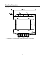
APPENDIX A: SPECIFICATIONS............................................................................... A-1
SPECIFICATIONS .................................................................................................................................A-1
DIMENSIONS: INDICATOR...................................................................................................................A-4
DIMENSIONS: OP-20 STAND ...............................................................................................................A-5
MOUNTING DIMENSIONS....................................................................................................................A-6
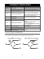
APPENDIX B: ERROR CODES.................................................................................. B-1
LOAD CELL OUTPUT COMPENSATION..............................................................................................B-1
APPENDIX C: FUNCITON LIST ................................................................................. C-1
FNCF—BASIC FUNCTIONS .................................................................................................................C-1
SQ F—WEIGHING SEQUENCE FUNCTIONS .....................................................................................C-4
IN F—CONTROL INPUT FUNCTIONS..................................................................................................C-7
OUTF—CONTROL OUTPUT FUNCTIONS ..........................................................................................C-8
SIF—STANDARD SERIAL OUTPUT FUNCTIONS ...............................................................................C-9
RSF—OP-03:RS-422/485/ OP-04:RS-232C FUNCTIONS .................................................................C-10
ANF—ANALOG OUTPUT FUNCTIONS .............................................................................................C-11
CALF—CALIBRATION FUNCTIONS ..................................................................................................C-12
APPENDIX D: GRAVITY ACCELERATION MAP ....................................................... D-1
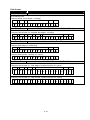
APPENDIX E: DATA OUTPUT EXAMPLES ............................................................... E-1
OUTPUT CONDITIONS.........................................................................................................................E-1
FORM E .................................................................................................................................................E-1
FORM F .................................................................................................................................................E-2
FORM G.................................................................................................................................................E-3
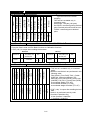
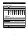
APPENDIX F: USER’S SETTING RECORD............................................................... F-1
FUNCTION SETTING RECORD ........................................................................................................... F-1
SET POINT SETTING RECORD ........................................................................................................... F-3
ii
SAFETY TERMS USED IN THIS MANUAL
Symbol
This is the symbol used for precautions. Read carefully where
appears and follow the
instructions to avioid injury or damage to your property.
Signal Words
Signal Words, “Danger”, “Warning”, and “Caution”, identify safety messages to the reader, and these
words mean the followings;
Important information to alert you to a situation that might cause
loss of life and serious injury.
DANGER
Important information to alert you to a situation that might cause
serious injury.
WARNING
Important information to alert you to a situation that might cause
injury.
CAUTION
iii
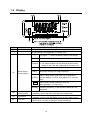
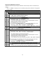
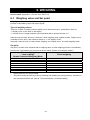
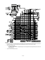
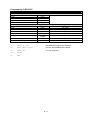
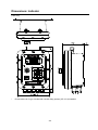
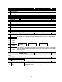
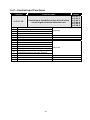
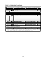
WARNING LABEL
A warning label is affixed to the product to call attention for the risk of explosion. Do not remove the
label and keep it readable at all times.
*
The picture above is of Type A model for weighing in the customer programmed control mode and
the built-in automatic program mode.) with the Conduit fittings options.
iv
SAFETY PRECAUTIONS FOR INSTALLATION
The indicator complies with “ExdIIBT5X” specifications for Explosion protected
devices. Install and use the indicator in a proper place to avoid explosion.
Environments
• Install and operate the indicator in Zone 1 or Zone 2. Never use in Zone 0.
• Do not install the unit in direct sunshine.
• Avoid vibration, sudden temperature changes, wind, water, or excessive
dirt.
• Operate in environments with temperatures of between -5°C to 40°C and
humidity of between 45% and 85% R.H. (non-condensing).
• Mount the unit on a solid frame or wall.
Installation work
DANGER
• Do engineering work and wiring in accordance with the requirements by
laws and regulations related to hazardous area devices.
• Only a trained professional with good knowledge of explosion protected
devices should be allowed to perform the installation work.
Grounding
• To avoid electrical shock and accident from static electricity, plug the power
cable into a properly wired earth grounded receptacle, or ground the “E”
terminal of Power source terminals before connecting anything else to any
of the instrument binding posts.
• Do not share grounding with other units that create electrical noise.
Power supply
• The power source should be 100 VAC +10%/-15% specification; with a
frequency of 50 or 60 Hz. Use a stable power source free from
instantaneous dropout or noise. Sharing a power line could result in
malfunctioning.
• Do not turn the power on until all the installation work has been completed.
Before opening the front panel
CAUTION
• Turn the power off (primary power) and wait approximately ten minutes for
the electrical charge to dissipate before opening the front panel.
The front panel door is thick and heavy. Be careful not to catch your finger in
the door.
SAFETY PRECAUTIONS DURING OPERATION
Disassembly/ Modification
Never try to disassemble or modify the unit. That may cause an explosion.
DANGER
When opening the Front panel.
Cut off the main power supply and wait 10 minute before opening the front
panel to avoid an explosion.
ABOUT THIS MANUAL
This manual provides setup and operating instructions for the AD-4403-FP Explosion protected
weighing indicator/ ST series indicator manufactured by A&D Company limited.
Read all information carefully and be fully knowledgeable about the unit before use. And after you read,
keep this manual at hand so that you can refer to it whenever necessary.
The contents of this manual and the specifications are subject to change for improvement without
notice.
v
1. INTRODUCTION
The AD-4403-FP/ ST is an Explosion protected weighing indicator to be installed and used in
hazardous area: Zone 1 and Zone 2 where explosive gas exists in the air. It complies with the
requirements from IEC (International Electrotechnical Commission) standard: Qualification number:
C13526)
1-1 Features
• Complies with “ExdIIBT5X” specifications for explosion protected devices (Qualification number:
C13526 )
• High speed sampling — 100 times per second.
• Five batch weighing modes and four check weighing modes.
• Two control modes;
• Type A: Normal batching/ Loss-in-weigh/ Nozzle controlled weighing mode
• Type B: Check weighing mode.
• Six input and six output terminals for the Control I/O.
• Up to 100 sets of set points are available. Each set is assigned a code number.
• Serial Interface and an buzzer are built in.
• Lithium battery backs up the data of zero compensation, tare weight, set point, and accumulation
data (weight and count).
• Non volatile memory stores the calibration and function setting data.
• Four 350-Ω load cells can be driven.
1-1
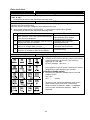
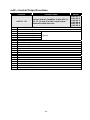
1-2 Front Panel
The picture above is of Type A model for normal batching/ loss-in-weigh/ nozzle controlled weighing mode) with the conduit fitting option.
#
Name
[1]
[2]
[3]
Hooks
Display
Buzzer
[4]
Operation Keys
[5]
Conduit fittings
Description
Used for lifting.
Displays weight, status, and messages. See {1-3 Display}
Sounds for a warning or when weighing completes. (selective)
Tare, Zero, and set / call / recall Set point and do settings.
Two kinds of Overlay: Type A and Type B.
See {1-4 Operation Keys }
Explosion-proof type fittings for wiring cables.
5 conduit fittings available. 2 fittings (fitting cable diameter: beyond 10
mm, up to 12 mm) are already with the unit. 3 more fittings can be
added. (OP-10 to 14).
1-2
1-3 Display
#
Name
[1]
Main Display
[2]
Sub display
Description
A 7-digit 7-segment display. Displays gross weight, net weight, etc
An 8-digit 7-segment display. The display content can be selected at
function settings. See {Appendix C: Function List }
“—“
[ZERO]
[3]
Status display
section (upper)
[4]
Status display
section (lower)
[5]
Right LEDs
[6]
Left LEDs
The upper “—” mark indicates the status of the weight.
Illuminates at the center-zero.
[STABLE]
• Illuminates at a stable reading.
• The stable condition can be changed at the function
setting of CALF-09. See, {Appendix C: Function List }
[GROSS]
Illuminates with the gross weight displayed.
[NET]
Illuminates with the net weight displayed.
Illuminates when the weight display is being held.
Either normal-hold or peak-hold can be selected at
[HOLD]
function settings, FncF-08. See {Appendix C: Function
List }
This display capability can be selected for an application.
AAAA
Select at the function settings of FncF-05.
See {Appendix C: Function List }
Illuminates when zero range error, weighing capacity
[ALARM] overflow, low battery, or accumulation data over have
happened.
• Illuminates when a set point output is turned on in the normal mode.
• Indicates a type of set point in the set point setting mode.
• Indicates a result of weighing.
• Indicates content of the sub display In the set point setting mode.
• Indicates content of the sub display.
• Blinks when it is ready to change or erase the settings.
1-3
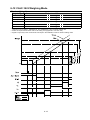
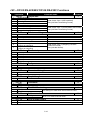
1-4 Operation Keys
Type A for the normal batching/ loss-in-weigh/ nozzle controlled weighing mode.
#
[1]
[2]
Name
[ZERO]
[7]
[UNDER]
[ANF]
[3]
[4]
[TARE]
[8]
[OVER]
[CALF]
[5]
[6]
[GROSS/NET]
[9]
[PRESET
TARE]
[7]
[ON/OFF]
[8]
[SET POINT]
[9]
[FUNC.]
[10]
[6]
[FULL]
[RSF]
Description
Returns the display to the center of zero. The range of zero can be set at
CALF-05. See { Appendix C: Function List}
Works as a numerical key, 7, used for settings.
Selects the “under limit” weight.
Enters the setting mode for the analog output (OP-07).
See {8-4 Option-07:Analog Output}
Subtracts the tare. When gross weight is “0”, it clears tare.
The tare subtraction condition can be set with CALF-10 and 11.
See {Appendix C: Function List}
Works as a numerical key, 8, used for settings.
Selects the “over limit” weight.
Enters the calibration mode.
See {4. Calibration}
Switches the display between “gross” and “net” weight.
Works as a numerical key, 9, used for settings.
Selects the “preset tare” weight.
• Turns ON and OFF the display in the normal mode.
• In the OFF mode, display and external I/Os are all off with the “O” mark on
the display.
• Available during operation.
(Press the key more than 0.3 seconds to activate.)
Selects a set point of the code input by numerical keys.
Enters the function setting mode. See {5-2. Function Settings}.
(Press the key more than 0.3 seconds to activate.)
Works as a numerical key, 6, used for settings.
Selects the “full” weight.
Enters the setting mode for the OP-03: RS-422/485, OP-04: RS-232C.
See {8-3 OP-03:RS-422/485, OP-04:RS-232C})
1-4
#
Name
[11]
[12]
[ENTER]
[F]
[13]
[ESC]
[14]
[3]
[PRELIM]
[INF]
[15]
[16]
[+/-]
[2]
[FREE FALL]
[SQF]
[0]
[17]
[18]
[19]
[20]
[CODE]
[1]
[FINAL]
[FNCF]
[5]
[ZERO BAND]
[SIF]
[4]
[OP. PRELIM]
[OUTF]
Description
Writes a value into memory or ends the setting.
Selects item. See FncF-02 {Appendix C: Function List}.
• Returns to the previous status.
• Escapes from the current operation.
• Mutes the sound of the buzzer.
Works as a numerical key, 3, used for settings.
Selects the “preliminary” weight.
Enters the setting mode for the control input.
See {Appendix C: Function List}.
• Sets a polarity + (blank) or -.
• Returns the setting to the previous.
• Sets a blank in the data.
Works as a numerical key, 2, used for settings.
Selects the “free fall” weight.
Enters the weighing sequence function mode. See {Appendix C: Function
List}.
Works as a numerical key, 0, used for settings.
• Selects a code number.
• Calls a set point of the code input by numerical keys.
• Edits (call/ retrieve/copy/erase) a set point by code.
• Selects set points of the code.
• Sets and changes set points of the code input by numerical keys.
Works as a numerical key, 1, used for settings.
Selects “final” weight.
Enters the basic function mode. See {Appendix C: Function List}.
Works as a numerical key, 5, used for settings.
Selects the “zero band” weight.
Enters the standard Serial Output mode. See {Appendix C: Function List}.
Works as a numerical key, 4, used for settings.
Selects the “optional preliminary” weight.
Enters the weighing sequence function mode. See {Appendix C: Function
List}.
1-5
Type B for the check-weighing mode.
#
[1]
Name
[ZERO]
[7]
[2]
[3]
[4]
[5]
[6]
[ANF]
[TARE]
[8]
[CALF]
[GROSS/NET]
[9]
[PRESET
TARE]
[7]
[ON/OFF]
[8]
[SET POINT]
[9]
[FUNC.]
[10]
[6]
[ZERO BAND]
[RSF]
Description
Returns the display to the center of zero. The range of zero can be set at
CALF-05. See { Appendix C: Function List}
Works as a numerical key, 7, used for settings.
Enters the analog output (OP-07) mode.
See {8-4 Option-07:Analog Output}
Subtracts the tare. When gross weight is “0”, it clears tare.
The tare subtraction condition can be set with CALF-10 and 11.
See {Appendix C: Function List}
Works as a numerical key, 8, used for settings.
Enters the calibration mode. See {4. Calibration}
Switches the display between “gross” and “net” weight.
Works as a numerical key, 9, used for settings.
Selects the “preset tare” weight.
• Turns ON and OFF the display in the normal mode.
• In the OFF mode, display and external I/Os are all off with the “O” mark on
the display.
• Available during operation.
(Press the key more than 0.3 seconds to activate.)
Selects a set point of the code input by numerical keys.
Enters the function setting mode. See {5-2. Function Settings}.
(Press the key more than 0.3 seconds to activate.)
Works as a numerical key, 6, used for settings.
Selects the “zero band” weight.
Enters the setting mode for the OP-03: RS-422/485, OP-04: RS-232C.
See {8-3 OP-03:RS-422/485, OP-04:RS-232C})
1-6
#
Name
[11]
[ENTER]
[12]
[F]
[13]
[ESC]
[14]
[3]
[Go]
[INF]
[15]
[16]
[+/-]
[2]
[Hi]
[SQF]
[0]
[17]
[18]
[19]
[20]
[CODE]
[1]
[Hi-Hi]
[FNCF]
[5]
[Lo-Lo]
[SIF]
[4]
[Lo]
[OUTF]
Description
Writes a value into memory or ends the setting.
Selects an item.
See FncF-02 {Appendix C: Function List}.
• Returns to the previous status.
• Escapes from the current operation.
• Mutes the sound of the buzzer.
Works as a numerical key, 3, used for settings.
Selects the “Go” weight in the check weighing mode.
Enters the setting mode for the control input.
See {Appendix C: Function List}.
Sets a polarity + (blank) or -.
Returns the setting to the previous.
Sets a blank in the data.
Works as a numerical key, 2, used for settings.
Selects the “Hi limit” weight in the check-weighing mode.
Enters the weighing sequence function mode.
See {Appendix C: Function List}.
Works as a numerical key, 0, used for settings.
• Selects a code number.
• Calls a set point of the code input by numerical keys.
• Edits (call/ retrieve/copy/erase) a set point by code.
• Selects set points of the code.
• Sets and changes a set point of the code input by numerical keys.
Works as a numerical key, 1, used for settings.
Selects the “Hi-Hi” weight in the check-weighing mode.
Enters the basic function mode. See {Appendix C: Function List}.
Works as a numerical key, 5, used for settings.
Selects the “Lo-Lo limit” weight in the check-weighing mode.
Enters the standard Serial Output mode. See {Appendix C: Function List}.
Works as a numerical key, 4, used for settings.
Selects the “Lo limit ” weight in the check-weighing mode.
Enters the weighing sequence function mode. See {Appendix C: Function
List}.
1-7
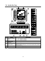
1-5 Inside the Case
#
[1]
[2]
[3]
[4]
[5]
[6]
Name
Calibration disable
switch
Wiring label
Control signal
terminals
Description
Disables the calibration function.
ON Calibration enabled
OFF Calibration disabled
Shows cable connections.
For control signal cables.
Turns on and off the power to the unit.
Keep the switch on during use. Use the main power switch outside to
turn the power off.
Fuse holder
Stores a 1A time-lag fuse
Power line terminals For the power line (100 VAC)
Power switch
1-8
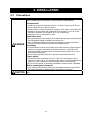
2. INSTALLATION
2-1 Precautions
The indicator complies with “ExdIIBT5X” specifications for Explosion protected
devices. Install and use the indicator in a proper place to avoid explosion.
Environments
•
•
•
•
Install and operate the indicator in Zone 1 or Zone 2. Never use in Zone 0.
Do not install the unit in direct sunshine.
Avoid vibration, sudden temperature changes, wind, water, or excessive dirt.
Operate in environments with temperatures of between -5°C to 40°C and
humidity of between 45% and 85% R.H. (non-condensing).
• Mount the unit on a solid frame or wall.
Installation work
DANGER
• Do engineering work and wiring in accordance with the requirements by laws
and regulations related to hazardous area devices.
• Only a trained professional with good knowledge of Explosion protected
devices should be allowed to perform the installation work.
Grounding
• To avoid electrical shock and accident from static electricity, plug the power
cable into a properly wired earth grounded receptacle, or ground the “E”
terminal of Power terminals before connecting anything else to any of the
instrument binding posts.
• Do not share grounding with other units that create electrical noise.
Power supply
• The power source should be 100 VAC +10%/-15% specification; with a
frequency of 50 or 60 Hz. Use a stable power source free from instantaneous
dropout or noise. Sharing a power line could result in malfunctioning.
• Do not turn the power on until all the installation work has been completed.
Before opening the front panel
CAUTION
• Turn the power off (primary power) and wait approximately ten minutes for
the electrical charge to dissipate before opening the front panel.
The front panel door is thick and heavy. Be careful not to catch your finger in the
door.
2-1
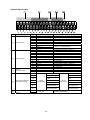
2-2 Wiring
Open the front panel door removing screws on the front panel, and connect a power cable, load cell
cables, and control signal cables to the terminals inside the case. Follow the instructions below.
Cable used
Load cell
Control signal cable
The use of a 6 wire shielded cable is recommended in order to reduce
weighing error. (When using a 4-wire cable, connect pin # 34 to # 35, and
pin # 36 to # 37.)
If the system requires two or more load cells, use an explosion-protected
type of summing box to input the signal into the indicator.
Use a shielded cable and connect its shield to pin # 40 (Frame ground).
Power cable
Terminal
Description
E
N
L
Ground
AC power supply
Load cell cable
Terminal
34
35
36
37
38
39
40
Description
EXC+
SEN+
SENEXCSIG+
SIGF.G.
Excitation +
Sense +
Sense Excitation Signal +
Signal Frame ground
2-2
Cable color
(ST Series only)
Red
Orange
Black
White
Green
Blue
Yellow
Control signal cable
#
[1]
Name
Control Input
[2]
Control output
[3]
OP-07
(Analog output)
[4]
OP-03 (RS-422/485)
OP-04 (RS-232C)
Pin #
1
2
3
4
5
6
7
8
9
10
11
12
13
14
15
16
17
18
19
20
21
22
23
24
25
Name
Common. Connected inside.
Frame ground
Control output function—OUTF-01
Control output function—OUTF-02
Common for output 1 and 2
No connection
Control output function—OUTF-03
Control output function—OUTF-04
Common for output 3 and 4
No connection
Control output function—OUTF-05
Control output function—OUTF-06
Common for Output 5 and 6
No connection
Analog Output (OP-07) High
Analog Output (OP-07) Low
Frame ground
RXD
26
SDB
TXD
27
RDA
RTS
28
29
OP-03
(RS-422/485)
31
Standard serial
output
Control input function—INF-01
Control input function—INF-02
Control input function—INF-03
Control input function—INF-04
Control input function—INF-05
Control input function—INF-06
SDA
30
[5]
Description
IN 1
IN 2
IN 3
IN 4
IN 5
IN 6
COM. 1
COM. 2
F.G.
OUT 1
OUT 2
COM. 1
N.C.
OUT 3
OUT 4
COM. 2
N.C.
OUT 5
OUT 6
COM. 3
N.C.
AN. OUT+
AN. OUTF.G.
32
33
RDB
TERM
S.G.
(Signal ground)
F.G.
(Frame ground)
C. Loop Out
OP-04
(RS-232C)
Standard Serial Output
2-3
CTS
DSR
S.G.
(Signal ground)
F.G.
(Frame ground)
Before closing the door
Place the cable on the heat sink board to avoid pinching the cable when closing the door.
2-4
2-3 Installing Conduit Fittings Option OP-10 - 14
Affix conduit fittings to the unit following the instructions below.
#
Parts Name
[1]
[2]
[3]
[4]
Lock nut
Gasket
Conduit fitting
Sealing tape
Procedures
2-5
1:
Wind the [4] Sealing tape around the
[3] Conduit fitting.
2:
Insert into the SERIAL hole through
the [2] Gasket.
3:
Tighten it with the [1] Lock nut.
2-4 Installing Wall-Mounting Fittings
WARNING
The fittings have been attached temporally when shipped. Before use, affix
the wall-mounting fittings securely to the back of the unit with screws. Be
sure to apply some threadlocker to the screws after fastening the screws to
avoid loosened screws that may cause accidents.
Install the wall-mounting fittings following the instructions below.
#
Parts Name
[1]
[2]
Four screws (M8)
Wall-mounting fittings
Placing
2-6
1:
Tighten the [1] screws at a torque of
50 kgf.cm or more.
2:
Apply some threadlocker to the
screws.
(Threadlocker should be type 262
manufactured by the LOCTTITE
company or an equivalent one with
90kgf.cm torque for a M8 screw)
[Blank page]
2-7
3. OPERATION
3-1 Turning the Power On
• Turning on the power switch inside the case illuminates all the display for 2 seconds, then to normal
display.
• [ON/OFF] turns the display on and off, not the power supply.
• When the power is turned OFF with “O” indicated (OFF mode), “O” will be displayed when turned
ON next time. And when turned off with a weight display (Normal mode), it displays the weight.
• This manual explains the operation based on the normal mode.
3-2 Basic Operation
Action
To set Zero.
To subtract Tare. When Gross weight is 0,
clear the tare weight.
To switch the display from “gross” to “net”
weight and vice versa.
To switch to the OFF mode from the normal
mode.
To recall a set point.
Key Operation
[ZERO]
[TARE]
[GROSS/NET]
[ON/OFF]
[UNDER]
[OVER]
[PRESET TARE]
[OP. PRELIM] ( [Lo] )
[ZERO BAND] ( [Lo-Lo] )
[FULL]
( [ZERO BAND] )
[FINAL]
( [Hi-Hi] )
[FREE FALL] ( [Hi] )
[PRELIM]
( [Go] )
[CODE]
3-1
* (Type B)
3-3 Setting and Recalling Set points
Setting set points
1. Enter the set point setting mode.
Press [CODE] [code number (2 digits)] [SET POINT] [ENTER] in this order. It shows;
Main display:
Sub display:
Status display section (lower):
Left LEDs:
*
*
*
“CodE XX”
“YYYYYY”
“FINAL” mark turns on.
“SET POINT” LED blinks.
Use numerical keys ([0] – [9]) to type a code number.
Set a blank for the code number with [+/-] to change the set point in use.
Press [ESC] to return to the normal mode.
2. Select a set point.
Select a set point with [F].
3. Input a set point.
*
Input a set point with numerical keys ([0] – [9]) and set polarity with [+/-].
Preset tare weight can be set up to the capacity. If exceeds, “dAtA Err” appears on the sub
display for 3 seconds. Try it again.
Press [ESC] to cancel the input. It returns to the previous value. (While the previous value is
displayed, press [ESC] to return to the normal mode.)
[+/-] may not work with some set points.
*
Press [ENTER] to store the set point into memory.
Settings won’t complete until [ENTER] is pressed.
*
*
4. Enter the set point into memory.
Recalling set points
1. Input a code number to recall.
*
*
*
Press [CODE] [code number desired (2 digits)] [ENTER] in this order.
Use numerical keys ([0] – [9]) to type a code number.
Press [ESC] to cancel the input and re-input. Or erase the digits typed with [+/-] and continue
typing.
Code numbers without the final weight setting can’t be recalled. In this case, “FinAL ” and
“not dAtA” are displayed for 3 seconds and returns to the normal mode.
3-2
3-4 Recalling through Clearing Accumulation data
1. Recall the accumulation data (weight and count).
Press [CODE] [code number (2 digits)] [F] in this order. It shows;
Main display: “CodE XX” (Code number)
Sub display: “YYYYYY” (Accumulated weight)
Left LEDs: “TOTAL” LED turns on.
*
*
*
Use numerical keys ([0] – [9]) to type a code number.
Press [ESC] to cancel the input and re-input. Or erase the digits typed with [+/-] and continue
typing.
Press [ESC] to return to the normal mode.
Recalling the accumulated count
Press [FUNC.] to recall the accumulated count. (Pressing [FUNC.] displays the accumulated
weight and the accumulated count alternately.) It shows;
Sub display: “nZZZZZZ” (Accumulated count)
Recalling the accumulation data in order of code number
Press [F] to recall in order of code number. The accumulation data of the code is displayed. Press
[F] to see the next.
Recalling the accumulation data designated by the code number
Press [CODE] [code number (2 digits)] [ENTER] in this order. The accumulation data of the code
is displayed.
2. Clear the accumulation data (if necessary).
Press [+/-] to select the accumulation data to be cleared. It shows;
Sub display: “CLEAr”
Left LEDs: “TOTAL” LED blinks.
Press [ENTER] to clear the data. it shows;
Sub display: “totAL”
Left LEDs: “TOTAL” LED blinks.
3. Escape from the accumulation data mode.
Press [ESC] to return to the normal mode.
3-3
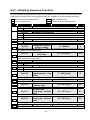
3-5 Editing Accumulation data
Set point editing modes
There are 8 modes for editing set point data.
Mode #
Mode name
Description
[0]
Mode 0
[1]
Mode 1
[2]
Mode 2
[3]
[4]
Mode 3
Mode 4
[5]
Mode 5
Retrieves the code number with no set point data setting.
Writes set point data over the set point designated by a code
number.
Clears the set point and accumulation data designated by a code
number.
Clears the accumulation data designated by a code number.
Displays all the set points that have been set.
Writes a tare weight over the preset tare weight designated by a
code number.
Clear all the set point data settings.
Clear all the accumulation data.
[7]
Mode 7
[8]
Mode 8
Mode [6] and [9] are not in use.
General procedures
1. Enter the set point editing mode.
Press [CODE] [FUNC.] in this order. It shows;
Main display: “CodE”
Sub display: “oPErAtE”
Right LEDs: All the LEDs is on while in the mode.
*
Press [ESC] to return to the normal mode.
*
Select a mode # from the above list with numerical keys.
Press [ESC] to return to the normal mode.
2. Select the mode required.
3. Follow the procedures of each mode.
Follow the procedures on the next page. See the following {Procedures for each mode}.
4. Escape from the set point editing mode.
Press [ESC] to return to the normal mode.
3-4
Procedures for each mode
Mode #
Name
Description
Display
[0]
Mode 0
Retrieves the code number with no set point data set.
“CodE bL”
Press [ENTER] to display the code number with no set point data It
returns to the set point editing mode after the action.
“SEArch ”
*
Press [ESC] to select another mode.
“SET POINT” LED: ON
Writes set point data over the set point designated by a
[1]
Mode 1
code number.
“CodE CP”
Input a 2-digit code number: “XX” to be copied, “YY” to be
“XX to YY”
written over.
*
*
*
*
Type “0” ahead for a single digit code like “01”.
“SET POINT” LED: Blinking
Press [F] to choose the set point data now in use. “--” is
displayed and that means “now in use”.
Press [+/-] to cancel the input and re-input.
Press [ESC] to return to the set point editing mode.
Press [ENTER] to overwrite the data. It returns to the set point
editing mode after the action.
If the data to be written over (“YY”) has a preset set point,
overwriting is not performed. “FaiLCoPy” is shown for 2
seconds and the unit a wait to be re-input.
Clears the set point and accumulation data designated by
a code number.
“CodE dt”
Input the 2-digit code number of the data to be cleared.
Press [+/-] to cancel the input and re-input.
“CLEAr
”
[2]
*
*
Press [ESC] to return to the set point editing mode.
Press [ENTER] to clear the data. It returns to the set point editing
mode after the action.
[3]
*
*
Mode 2
Mode 3
“SET POINT” LED: Blinking
Clears the accumulation data
Input the 2-digit code number of the data to be cleared.
Press [+/-] to cancel the input and re-input.
Press [ESC] to return to the set point editing mode.
Press [ENTER] to clear the data. It returns to the set point editing
mode after the action.
3-5
“CodE tL”
“CLEAr
”
“TOTAL” LED: Blinking
Mode #
[4]
*
*
*
Name
Mode 4
Description
Display
Displays all the set points that have been set.
“CodE
”
Input the 2-digit code number of the data to be displayed.
Press [+/-] to cancel the input and re-input.
“ALL diSP”
Press [ESC] to return to the set point editing mode.
Press [F] [ENTER] to display the set point data designated by the
code number.
Press [F] to jump to a code with no set point data.
The type of set point is not changed.
Press [ENTER] several times to select a type of set point. Display
shows;
“SET POINT” LED: Blinking
(Type A for normal batching/ loss-in-weigh/ nozzle controlled
weighing mode)
Final→ Free fall→ Preliminary→ Over limit→ Under limit→ Zero
band→ Full→ Preset tare
(Type B for the check-weighing mode.)
Zero band→Hi-Hi→Hi→Go→Lo→Lo-Lo→ Preset tare
In case of “Preset tare”, press [ENTER] to jump to a code with set
point data.
After displaying all the data, the mode returns to the set point editing
mode.
Writes a tare weight over the preset tare weight
designated by a code number.
“CodE
”
Input the 2-digit code number of the preset tare weight data to be
overwritten with the tare weight.
“tr CoPy”
[5]
*
*
Mode 5
Press [+/-] to cancel the input and re-input.
Press [ESC] to return to the set point editing mode.
Press [ENTER] to overwrite the data. It returns to the set point
editing mode after the action.
[7]
“SET POINT” LED: Blinking
Clears all the set point data that has been set.
“CodE dt”
Press [ENTER] for more than 0.3 seconds to clear all the set point
data that have been set. (Accumulation data, weight and counts,
“ALL CLE”
*
*
won’t be cleared.)
“SET POINT” LED: Blinking
Press [ESC] to return to the set point editing mode.
Perform Mode 7 and 8 to clear both set point data and accumulation
data.
[8]
*
*
Mode 7
Mode 8
Clears all the accumulation data that has been set.
“CodE tL”
Press [ENTER] for more than 0.3 seconds to clear all accumulation
data that has been set.
“ALL CLE”
Press [ESC] to return to the set point editing mode.
“TOTAL” LED: Blinking
Perform Mode 7 and 8 to clear both set point data and accumulation
data.
3-6
4. CALIBRATION
Section related:
{Appendix C:FUNCITON LIST: CALF―Calibration Functions}
{Appendix B:Erro codes}
4-1 General
There are three ways to calibrate zero and span.
Digital span calibration
Calibrates with load cell output voltage.
Actual load calibration
Calibrates with weights.
Gravity compensation
Sets the know acceleration rate (“g”) for your location
4-2 Digital Span Calibration
This is calibration using the load cell output voltage (mV/V) instead of weights. Function CAL-19 and
CAL-20 configures the calibration function. See {Appendix C: FUNCTION LIST: CALF—Calibration
Functions}.
1. Enter the zero voltage.
Enter the load cell output voltage at the zero point with numerical keys.
2. Enter the span voltage.
Enter the difference of the load cell output voltage between at the capacity and at the zero point.
3. Relate the span voltage with weight.
Relate the span voltage with displaying weight.
4-3 Actual load Calibration
Before actual load calibration
AD-4403-FP
ST Series
• Perform “Gravity compensation” before the
actual load calibration. ( “g” must be set with or
without the actual load calibration.
• The scale has been calibrated at factory before
shipment. However it must be re-calibrated at
your location due to a change in gravity
acceleration.
• Turn the adjustable leveling feet until the level
spirit shows that the platform is level before the
actual load calibration.
• Connect the load cell cables before turning the power on. Calibration may not be done properly if
connected after the power is turned on.
• Set the calibration disable switch (inside the case) to the ON position to perform calibration.
• In order to avoid influence by temperature drift, carry out this calibration 10 minutes or more after
turning on the power.
Weighing unit (CAL-01), decimal point position
(CAL-02), and, capacity (CAL-03) should be set in
prior to calibration. See {Appendix C: Function
List}
4-1
Actual load calibration procedures
Calibration procedures vary by the type of calibration. Follow the step number in the table below to
calibrate.
*
When “C ErrXX” is displayed, there is something wrong with the calibration. See {Appendix
B: Error Codes}.
Zero calibration only
Span calibration only
Zero and Span calibration
Get in the calibration mode.
1
1
1
*
Press [CALF] while pressing [ENTER] in the normal mode, and press [ENTER] next.
“CAL Set” is displayed. (ready to calibrate)
Press [ESC] to return to the normal mode.
Calibrate Zero.
*
2
2 *
*
Press [ENTER] to get into the zero calibration mode.
”
Main display: “CAL 0” / Sub display: “
To browse the gross weight, press [SET POINT], it will be displayed on the sub
display. Press [SET POINT] to erase this display.
Press [ESC] to return to the normal mode.
Press [ENTER] at a stable reading (“-” is on beneath “Stable”) with no load.
“-------” is displayed for 2 seconds and the displays show;
Main display: “CAL SPn” / Sub display: “ Capacity weight ”
To end calibration without zero calibrated, press [ESC], “CAL End” is displayed.
Move on to Span calibration.
2
To skip zero calibration and perform span calibration only, press [ENTER]. When
“CAL 0” is displayed, press [F].
Calibrate Span.
The displays show;
Main display: “CAL
*
*
3
3 *
*
SPn” / Sub display: “ Capacity weight ”
The capacity weight is of the value set in CALF-04.
To browse the gross weight, press [SET POINT], it will be displayed on the sub
display. Press [SET POINT] to erase this display.
Press [ESC] to return to the normal mode.
To end calibration without span calibrated, press [ESC], “CAL End” is displayed.
Input the weight of the calibration mass using the numerical keys of ([0] - [9]).
Press [ENTER] at a stable reading (“-” is on beneath “Stable”).
“-------” is displayed for 2 seconds and the displays show;
Main display: “CAL End” / Sub display: “
”
End Calibration after saving the calibration data in EEPROM.
3
4
4
*
Press [ENTER] to save the calibration data in the EEPROM and return to the normal
mode.
To return to the normal mode without saving the calibration data, press [ESC].
4-2
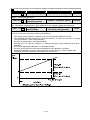
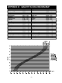
4-4 Gravity compensation
1. Get in the calibration mode
*
Press [CALF] while pressing [ENTER] in the normal mode, and press [ENTER] next. “CAL
Set” is displayed. (ready to calibrate)
Press [ESC] to return to the normal mode.
*
Press [FUNC.]. “GrAvity” is displayed on the main display and your “g” value is on the
sub-display..
Press [ESC] to return to the normal mode.
*
*
Refer to {Appendix D: Gravity acceleration map} and enter the value on the map.
Press [ENTER] to save the calibration data.
Press [+/-] to cancel the input and re-input.
Press [ESC] to return to the normal mode.
2. Get in the Gravity compensation mode
3. Enter the know acceleration rate for your location
4-3
5. FUNCTION SETTINGS
Section related: {Appendix C: Function list:}
The functions determine the operations of the indicator and each function is sorted into the groups by
capabilities and represented by prefixing its group name.
*
All the function setting are done in the same manner except for FuncF-01.
*
All the setting information is stored in the EEPROM.
5-1 General
Function group
Display
“FncF ”
“Sq F-”
“in F-”
“outF-”
“Si F-”
“rS F-”
“An F-”
“CALF-”
Basic functions
Weighing sequence functions
Control input Functions
Control output functions
Standard serial output functions
OP-03:RS-422/485/ OP-04:RS-232C functions
OP-07 (analog output) functions
Calibration Functions
5-1
Function Key
[FNCF]
[SQF]
[INF]
[OUTF]
[SIF]
[RSF]
[ANF]
[CALF]
5-2 Function Settings
1. Enter the function setting mode.
*
*
Press [FUNC.] for 0.3 seconds or longer in the normal mode.
“Function” is displayed on the sub display.
[FUNC.] will not work unless pressed for 0.3 seconds or longer.
Press [ESC] to return to the normal mode..
2. Press a function key.
*
Select and press a function key from the table {5-1. General} to set or see function setting
information.
If the wrong key pressed, press [ESC] and return to the normal.
Example: Performing basic function setting.
Press [FUNC.]. Displays show;
Main display: “FncF-” / Sub display: “
”
3. Input a function number.
*
Input a function number with the numerical keys of [0] - [9] referring to the table {Appendix C:
Function List}.
If the wrong number selected, press [ESC] and re-input.
Press [ENTER] to enter the setting of the function number.
Press [ENTER] again. The current parameters are displayed.
Example: Performing FncF-02 setting.
Press [2] and [ENTER] in this order for the function number “02”. Displays show;
Main display: “FncF- 2” / Sub display: “
”
Press [ENETER] again. Displays show;
Main display: “FncF- 2” / Sub display: “
0” (a current value)
4. Set a parameter to the function.
*
Set a parameter with the numerical keys of [0] - [9] and [+/-].
If the wrong parameter has been typed in, press [ESC] to return to the previous value. It returns to
the ready-to-input status.
Press [ENTER] to proceed. The next function number is displayed.
If more functions are to be set, set them using the procedures for step 3 and 4.
Example: Setting a parameter for FncF-02=1.
Press [1] for FncF-02=1. Displays show;
Main display: “FncF- 2” / Sub display: “
Press [ENTER], next number is displayed.
Main display: “FncF- 3” / Sub display: “
1” (a new value)
”
5. Escape from the function setting mode.
*
Press [FUNC.] to escape from the function setting mode. Function setting data is stored in the
EEPROM and returns to the normal mode.
[FUNC.] will not work when a value is displayed on the sub display. In that case press [ENTER] so
that a function number is ready to be input, then press [FUNC.].
5-2
6. WEIGHING
Section related: {Appendix C: Function List—CALF-14}
6-1 Weighing value and Set point
Weighing is performed comparing the weighing value with “Set point” values, and the weighing
process is controlled by input and output signals.
Type of weighing values
There are 2 types of weighing values: Display count and internal count. (Selectable in SqF-01)
• “Display count” is the value on the display.
• “Internal count” is a high-resolution value calculated with a minimum division of 1.
Internal count has more accuracy. However in check weighing using a platform scale, “Display count”
is suitable for use. Also, if the minimum division is 1, use “Display count”.
Generally, “internal count” is used in batch weighing, and “Display count” for check weighing mode.
Set point
Set point is a value to be compared with a weighing value, and the weighing process is controlled by
the set point. The indicator has set points as shown below. (Differs from weighing modes)
Batch weighing
Loss-in weigh
Nozzle Controlled Weighing Mode
Check weighing
*
Final
Free fall
Preliminary
Optional preliminary
Over limit
Under limit
Zero band
Full
Battery backs up the set point data.
Go
N/A
Hi-Hi
Lo-Lo
Hi
Lo
Zero band
N/A
*
Set points can be set from keys (See {3-3.Setting and recalling set points}) and by a command in
the command mode as well. (See {8-7 Command Mode—Command SSXX})
6-1
6-2 Weighing Modes
The indicator-FP has 10 weighing modes, which vary from the weighing method (normal batching or
loss-in weigh) and with/without a PLC (Programmable Logic Controller).
Choose the mode suitable for your weighing at CALF-14. (See {Appendix C: Function List})
Utility
PLC.
In use
1)
Hopper
scale
Not in
use
2)
Type of weighing
Normal batching 3)
Loss-in-weigh 4)
Normal
batching
3)
Without supplementary flow
With supplementary flow
Loss-in-weigh 4)
Nozzle Controlled Weighing Mode 5)
Platform
Scale,
Check
weighing
scale
1)
In use
1)
Check
weighing
6)
3-stage check weighing
with Over/Under limit
weight-deviation
5-stage check weighing
3-stage check weighing
with Over/Under limit
weight-deviation
5-stage check weighing
Weighing mode
Section
Normal batching
(Customer Programmed Control Mode)
Loss-in-weigh
(Customer Programmed Control Mode)
Normal batching
(Built-in automatic program mode)
Normal batching
(Built-in automatic program mode)
Loss-in-weigh
(Built-in automatic program mode)
Nozzle Controlled Weighing Mode
(Built-in automatic program mode)
6-3
Check weighing 1
6-9
Check weighing 2
6-10
Check weighing 3
6-11
Check weighing 4
6-12
6-4
6-5
6-6
6-7
6-8
PLC in use:
A programmed PLC is required besides the indicator to control the weighing process.
2)
PLC not in use:
The built-in program of the indicator controls the weighing process.
3)
Normal batching:
Weighs ingredient, controlling the increase in weight by comparing the measured weight with the
set point weight.
4)
Loss-in-weigh:
Weighs ingredient, controlling the loss in weight by comparing the measured weight with the set
point weight.
5)
Nozzle Controlled Weighing Mode:
Normal batching mode with tare function and nozzle control function.
6)
Check weighing:
Weighs ingredient by comparing the measured weight with the target weight, and judges the
result in three ranks, Hi, Go, Lo.
6-2
[Blank page]
6-3
6-3 CALF-14=“1” Weighing Mode
(Normal batching in customer programmed control mode)
Output signal
Output condition
Zero band
Full-flow
medium-flow
Dribble-flow
Over limit
Under limit
Final
Final
Final
Final
- Optional preliminary
Preliminary
Free fall
+
Over limit
≤
≤
≤
<
Gross weight ≤ Zero band
Net weight
Net weight
Net weight
Net weight
Net weight <
Final
- Under limit
• When an output condition is established, a relevant output terminal is turned on (power continuity with output COM).
• An output terminal number can be selected with OUTF-01 through OUTF-08. See {Appendix C: Function List}
• A set point signal output is turned off unconditionally when the operation mode is other than the normal mode.
Weighing process
*
Programming with a PLC (Programmable Logic Controller) is required for this weighing mode.
Sequence #
1
Process
•
•
•
•
2
3
4
5
•
•
•
•
•
•
•
•
•
*
•
*
The “Tare” signal is input.
The display shows “0”.
Gates G1 (full-flow), G2 (medium-flow), and G3 (dribble-flow) open.
The weight on the display is incremented, and reaches the weight of “Final –
Optional preliminary”.
The “Optional preliminary” output is turned ON.
Gate G1 closes.
The display shows the weight of “Final – Preliminary”.
The “Preliminary” output is turned ON.
Gate G2 closes.
The display shows the weight of “Final – Free fall”.
The “Final” output is turned ON.
Gate G3 closes.
Weighing completes at a stable display.
The display shows the final weight, indicating that hopper 2 has been filled to
that weight. Use the over limit/under limit setting to check whether the
weighing value is within limits.
Gate G4 (Discharging gate) opens to discharge and fill the container.
The use of the zero range setting can check if the ingredient has been
completely discharged.
6-4
6-5
6-4 CALF-14=“2” Weighing Mode
(Loss-In-weigh in customer programmed control mode)
Output signal
Output condition
Zero band
Full
Full-flow
Medium-flow
Dribble-flow
Over limit
Under limit
Full
Final - Optional preliminary
Final Preliminary
Final Free fall
Final +
Over limit
≤
≤
≤
≤
<
Gross weight
Gross weight
- Net weight
- Net weight
- Net weight
Net weight
- Net weight
≤ Zero band
< Final
- Under limit
• When an output condition is established, a relevant output terminal is turned on (power continuity with output COM).
• An output terminal number can be selected with OUTF-01 through OUTF-08. See {Appendix C: Function List}
• A set point signal output is turned off unconditionally when the operation mode is other than the normal mode.
Weighing process
*
Programming with a PLC (Programmable Logic Controller) is required for this weighing mode.
*
Difference from the normal batching is that the loss-in weigh has “full” output and the comparison
is done with a negative net weight.
Sequence #
Process
• With the weighing hopper 2 being empty, the gross weight is within the zero
range.
• Gate G1 (Filling gate) opens.
• The weight on the display is incremented, and reaches the “Full” weight.
2
• The “Full” output is turned ON.
• Gate G1 closes. (Weighing hopper 2 has been filled.)
• The “Tare” signal is input.
3
• The display shows “0”.
• Gates G2 (full-flow), G3 (medium-flow), and G4 (dribble-flow) open.
• The display shows the weight of “Final – Optional Preliminary”.
4
• The “Optional Preliminary” output is turned ON.
• Gate G2 closes.
• The display shows the weight of “-(Final – Preliminary)”.
5
• The “Preliminary” output is turned ON.
• Gate G3 closes.
• The display shows the weight of “-(Final – Free fall)”.
• The “Final” output is turned ON.
• Gate G4 closes.
6
• Weighing completes at a stable display.
*
The indicator shows the final weight(negative), indicating that hopper 3 has
been filled to that weight. The use of over limit/under limit setting can check
whether the weight is within limits.
• When the volume of ingredient left in the weighing Hopper 2 becomes less
than the Zero band.
7
• The “Zero band” output signal is turned on.
Note: SQF-21/ SQF-22 setting enables to add automatically Final weight to Zero band or Full.
1
*
Therefore there is always enough ingredient left in the hopper for a measurement.
6-6
6-7
6-5 CALF-14=“3” Weighing Mode (with no Supplementary Flow)
(Normal batching in built-in automatic program mode)
Output signal
Output condition
Zero band
Full-flow
Medium-flow
Dribble-flow
Over limit
Under limit
Final
Final
Final
Final
- Optional preliminary
Preliminary
Free fall
+
Over limit
≤
≤
≤
<
Gross weight ≤ Zero band
Net weight
Net weight
Net weight
Net weight
Net weight <
Final -
Under limit
• When an output condition is established, full flow, medium flow, and dribble flow outputs are turned off, but the other
outputs are turned on.
• Once the full flow, medium flow, and dribble flow are turned off, they are not turned on until the next start of batching.
• Over limit / Under limit is activated based on the net weight upon batch finish. (May be changed to customer
programmed control mode operation)
• The zero band is a customer programmed control mode operation.
Weighing process
Sequence #
1
2
3
4
5
6
7
8
9
10
11
12
Process
• “Batch start” or “Discharge start”signal is ready to be input.
•
•
•
•
•
•
•
•
•
•
•
•
•
•
•
•
•
•
•
•
•
•
•
•
•
•
•
•
•
•
•
•
•
•
•
*
The “Batch start” signal is input.
The “Batch start wait timer” starts.
The “Batch start wait timer” completes the set time.
“Full-flow”, “Medium-flow” and “Dribble-flow” output signals are turned on.
The “Full-flow comparator inhibitor timer” and “Batch monitoring timer” start.
Net weight reaches the weight of “Final” –“Optional preliminary” or more.
The “Full-flow” output is turned off.
The “Medium-flow comparator inhibitor timer” start.
Net weight reaches the weight of “Final” –“Preliminary” or more.
The “Medium-flow” signal is turned off.
The “Dribble-flow comparator inhibitor timer” starts.
Net weight reaches the weight of “Final” –“Free fall” or more.
The “Dribble-flow” signal is turned off.
The “Judgment wait timer” starts.
The “Judgment wait timer” completes the set time.
Display becomes stable.
If automatic free fall compensation is being used, its calculation will be made.
The “Batch Finish” output signal is turned on
If there is excess or shortage, a judgment result output signal (over limit or under limit) will
be turned on. (“Within limit” is on in the chart on next page.)
The “Batch monitoring timer” is reset.
The net weight is accumulated automatically.
The data is output from the interface set for auto print.
The “Discharge start” signal is input.
The “Discharge start wait timer” starts.
The “Discharge start wait timer” completes the set time.
The “Discharge output“ signal is turned on.
The “Discharging time monitor timer” starts.
Gross weight reaches 0 or less.
The “Discharge valve close wait timer” starts.
The “Discharging time monitor timer” is reset.
The “Discharge valve close wait timer” completes the set time.
The “Discharge output “ signal is turned off.
The “Batch start” input signal for the next cycle is input.
The “Batch finish” output signal is turned off.
The judgment result output signal (Over limit or Under limit) is turned off.
Now, the weighing sequence has cycled and restarts from sequence # 2 at this time.
6-8
Note
*
In the case of built-in-automatic program mode weighing, the set point data is held until batch finish since batch
start. Therefore, a set point altered during batching takes effect after “batch finish” is output.
*
“Within limit” is on in the chart above.
6-9
6-6 CALF-14=“3” Weighing Mode (with Supplementary Flow)
(Normal batching with supplementary flow in built-in automatic program mode)
Supplementary flow automatically turns on the dribble flow for the specified time when the loaded weight is not sufficient.
To make supplementary flow, set the “maximum supplementary flow times, SQF-08,” to other than 0, and the
“supplementary flow open timer, SQF-16,” and “supplementary flow close timer, SQF-17,” to their respective times. See
{Appendix C: Function List}
Supplementary flow is also available in loss-in-weigh (built-in automatic program mode).
Weighing process
Sequence #
1
2
3
4
5
6
7
8
9
10
11
12
13
14
15
16
Process
• “Batch start” or “Discharge start”signal is ready to be input.
•
•
•
•
•
•
•
•
•
•
•
•
•
•
•
•
•
•
•
•
•
•
•
•
•
•
•
•
•
•
•
•
•
•
•
•
•
•
•
•
•
•
•
•
•
•
•
•
•
*
The “Batch start” signal is input.
The “Batch start wait timer” starts.
The “Batch start wait timer” completes the set time.
“Full-flow”, “Medium-flow” and “Dribble-flow” output signals are turned on.
The “Full-flow comparator inhibitor timer” and “Batch monitoring timer” start.
Net weight reaches the weight of “Final” –“Optional preliminary” or more.
The “Full-flow” output is turned off.
The “Medium-flow comparator inhibitor timer” start.
Net weight reaches the weight of “Final” –“Preliminary” or more.
The “Medium-flow” signal is turned off.
The “Dribble-flow comparator inhibitor timer” starts.
Net weight reaches the weight of “Final” –“Free fall” or more.
The “Dribble-flow” signal is turned off.
The “Judgment wait timer” and “Batch monitoring timer” start.
The “Judgment wait timer” completes the set time.
Display becomes stable.
If automatic free fall compensation is being used, its calculation will be made.
If net weight is insufficient, the “Dribble-flow” signal will be turned on.
The “Supplementary flow timer” starts.
The “Supplementary flow timer” completes the set time.
The “Dribble-flow “ signal is turned off.
The “Supplementary flow close timer” starts.
The “Supplementary flow close timer” completes the set time.
It is checked whether the net weight is insufficient.
If insufficient, the “Dribble-flow “ signal is turned on without waiting for a stable reading.
The “Supplementary flow open timer” starts.
The “Supplementary flow open timer” completes the set time.
The “Dribble-flow “ signal is turned off.
The “Supplementary flow close timer” starts.
The “Supplementary flow close timer” completes the set time.
It is checked whether the net weight is insufficient.
If NOT sufficient, the “Batch finish “ signal is turned on without waiting for a stable reading.
A judgment result output signal (Within limit or Over limit) will be turned on. (“Within limit” is on
in the chart on next page.)
The “Batch monitoring timer” is reset.
The net weight is accumulated automatically.
The data is output from the interface set for auto print.
The “Discharge start “ signal is turned on.
The “Discharge start wait timer” starts.
The “Discharge start wait timer” completes the set time.
The “Discharge “ signal is turned on.
The discharging time monitor timer starts.
Gross weight reaches less than the weight of “Zero band”.
The “Discharge valve close wait timer” starts.
The “Discharging time monitor timer” is reset.
The “Discharge valve close wait timer” completes the set time.
The “Discharge“ signal is turned off.
The “Batch start” input signal for the next cycle is input.
The “Batch finish” output signal is turned off.
The judgment result output signal (Over limit or Under limit) is turned off.
Now, the weighing sequence has cycled and restarts from sequence # 2 at this time.
6-10
Note
*
In the case of built-in-automatic program mode weighing, the set point data is held until batch finish since start of
batching. Therefore, a set point altered during batching takes effect after “batch finish” is output.
*
The chart above is the case that a judgement result becomes “Within limit” at the third judgement after
supplementary flow action has been made twice.
6-11
6-7 CALF-14=“4” Weighing Mode
(Loss-In-weigh in built-in automatic program mode)
Output signal
Output condition
Zero band
Full
Full-flow
Medium-flow
Dribble-flow
Over limit
Under limit
Final
Final
Final
Final
Full
- Optional preliminary
Preliminary
Free fall
+
Over limit
≤
≤
≤
≤
<
Gross weight
Gross weight
Net weight
Net weight
Net weight
Net weight
Net weight
≤ Zero band
<
Final
- Under limit
• When an output condition is established, full flow, medium flow, and dribble flow outputs are turned off, but the other
outputs are turned on.
• Once the full flow, medium flow, and dribble flow are turned off, they are not turned on until the next start of batching.
• Over limit / Under limit is activated based on the net weight upon batch finish. (May be changed to customer
programmed control mode operation)
• The zero band is a customer programmed control mode operation.
Weighing process
Sequence #
1
2
3
4
5
6
7
8
Process
•
•
•
•
•
•
•
•
•
•
•
•
•
•
•
•
•
•
•
•
•
•
The “Zero band” is output.
Ingredient continues to be supplied until the “Full” signal is output.
The “Tare” signal is input at stable display.
The “Batch start” signal is input.
The “Batch start wait timer” starts.
The “Batch start wait timer” completes the set time.
“Full-flow”, “Medium-flow” and “Dribble-flow” output signals are turned on.
The “Full-flow comparator inhibitor timer” and “Batch monitoring timer” start.
Net weight reaches the weight of “Final” –“Optional preliminary”.
The “Full-flow” output is turned off.
The “Medium-flow comparator inhibitor timer” starts.
Net weight reaches the weight of “Final” –“Preliminary” or more.
The “Medium-flow” signal is turned off.
The “Dribble-flow comparator inhibitor timer” starts.
Net weight reaches the weight of “Final” –“Free fall” or more.
The “Dribble-flow” signal is turned off.
The “Judgment wait timer” starts.
The “Judgment wait timer” completes the set time.
Display becomes stable.
If automatic free fall compensation is being used, its calculation will be made.
The “Batch Finish” output signal is turned on
If there is excess or shortage, a judgment result output signal (Over limit or
Under limit) will be turned on. (“Within limit” is on in the chart on next page.)
• The “Batch monitoring timer” is reset.
• The net weight is accumulated automatically.
• The data is output from the interface set for auto print.
6-12
Note
*
*
SQF-21/ SQF-22 setting enables to add automatically the Final weight to Zero band or
Full. Therefore there is always enough ingredient left in the hopper for a measurement.
In the case of built-in-automatic program mode weighing, the set point data is held until
batch finish since start of batching. Therefore, a set point altered during batching takes
effect after “batch finish” is output.
6-13
6-8 CALF-14=“5” Weighing Mode
(Nozzle controlled weighing mode)
Output signal
Zero band
Full-flow
Medium-flow
Dribble-flow
Over limit
Under limit
Final
Final
Final
Final
Output condition
- Optional preliminary
Preliminary
Free fall
+
Over limit
≤
≤
≤
<
Gross weight
Net weight
Net weight
Net weight
Net weight
Net weight
≤ Zero band
<
Final
- Under limit
• When an output condition is established, a relevant output terminal is turned on or off. “Full flow”, “Medium flow”,
and ”Dribble flow”: OFF, the other outputs: ON.
• Once the full flow, medium flow, and dribble flow are turned off, they are not turned on until the next start of batching.
• Over limit / Under limit is activated based on the net weight upon batch finish. (May be changed to customer
programmed control mode operation)
• The zero band is a customer programmed control mode operation.
Weighing process
#
Process
1
2
3
4
5
• [ZERO] is pressed.
• Gross weight becomes ”0”.
• A container is placed on the weighing platform.
• [TARE] is pressed
If SqF-26=”1”:Tared at batch start automatically
• Weight is tared at sequence # 4. Automatically.
• Weight is tared.
• Net weight becomes “0”.
• The “Batch start” signal is input.
If SqF-26=”1”:Tared at batch start automatically
• Weight is tared at the “Batch start” input.
• (Tare action is the same as [TARE].)
• The “Batch start wait timer” will start 1 second (time
for visual inspection for the tare action) later.
• The “Nozzle down” signal is turned on.
• The “Batch start wait timer” starts.
• The “Batch start wait timer” completes the set time.
• “Full-flow”, “Medium-flow” and “Dribble-flow”
output signals are turned on.
• The “Full-flow comparator inhibitor timer” and
“Batch monitoring timer” start.
6
• Net weight reaches the weight of “Final” –“Optional
preliminary” or more.
• The “Full-flow” output is turned off.
• The “Medium-flow comparator inhibitor timer”
starts.
7
• Net weight reaches the weight of “Final”
–“Preliminary” or more.
• The “Medium-flow” signal is turned off.
• The “Dribble-flow comparator inhibitor timer”
starts.
8
• Net weight reaches the weight of “Final” –“Free
fall” or more.
• The “Dribble-flow” signal is turned off.
• The “Judgment wait timer” starts.
9
• The “Judgment wait timer” completes the set time.
• Display becomes stable. (Already "Stable" in the
chart on next page.)
• If automatic free fall compensation is being used,
its calculation will be made.
• Judgement is made.
#
9
10
11
12
6-14
Process
(Continued)
In case of No supplementary flow
• Supplementary flow is not made when;
• If SqF-09≠”0” and judgement result is either
“Acceptable weight” or “Over limit”.
• If SqF-09=”0”: No supplementary flow setting.
• Net weight is judged and either “Over limit”,
“Acceptable weight”, or “Under limit” signal is
turned on based on judgement result.
• The “Batch monitoring timer” is reset.
• The net weight is accumulated automatically.
• The data is output from the interface set for auto
print.
• Weighing process leads to sequence #13.
In case that supplementary flow is made
• Supplementary flow is made when;
• If SqF-09≠”0” and judgement result is
“Under limit”.
• The “Nozzle down “ signal is turned on.
• The “Batch monitoring timer” starts.
• The “Batch monitoring timer” completes the set
time.
• The “Dribble-flow“ signal is turned off.
• The “Supplementary flow open timer” starts.
• The “Supplementary flow open timer” completes
the set time.
• The “Dribble-flow“ signal is turned off.
• The “Nozzle down“ signal is turned off.
• The “Supplementary flow close timer” starts.
• The “Supplementary flow close timer” completes
the set time.
• Judgement is made.
If “Under limit”;
• Repeat the weighing process from sequence # 9.
If “Acceptable weight” or “Over limit”;
• The “An acceptable weight” or “Over limit” is
turned on.
• The batch monitoring timer is reset.
• The net weight is accumulated automatically.
• The data is output from the interface set for auto
print.
13
• The container has been filled with ingredient.
• The container is removed from the platform
14
• To tare, input Tare signal or press [TARE].
• If Sq F-26=”1”(Tared automatically at batch start), tare
is cleared automatically within zero band.
Note
*
*
*
In the case of built-in-automatic program mode weighing, the set point data is held until batch finish since start of
batching. Therefore, a set point altered during batching takes effect after “batch finish” is output.
Chart above is of the case;
• “Acceptable weight” is on.
• A judgement result becomes “Acceptable weight” at the third judgement after supplementary flow action has
been made twice.
SqF-26=”0”:Not tared at batch start
6-15
6-9 CALF-14=6 Weighing Mode
(Check weighing 1)
Output signal
Zero band
Hi-Hi
Hi
Go
Lo
Lo-Lo
Target weight +
Target weight -
Output condition
Hi-Hi limit
Hi limit
Lo limit
Gross weight
< Net weight
< Net weight
≤ Net weight
Net weight
Net weight
≤ Zero band
≤ Target weight
< Target weight
<
Lo-Lo limit
+ Hi limit
- Lo limit
• When an output condition is established, a relevant output terminal is turned on (power continuity with the output
common) or off. “Full flow”, “Medium flow”, and ”Dribble flow”: OFF, the other outputs: ON.
• Select an output terminal at the outF-01-06 setting. See {Appendix C: Function List}.
• Signal is output only in the normal mode. No output in the calibration mode nor function setting mode.
6-16
6-10 CALF-14=7 Weighing Mode
(Check weighing 2)
Output signal
Zero band
Hi-Hi
Hi
Go
Lo
Lo-Lo
Target weight
Target weight
Target weight
Target weight
Output condition
+ Hi-Hi limit
+
Hi limit
Lo limit
- Lo-Lo limit
<
<
≤
≤
Gross weight
Net weight
Net weight
Net weight
Net weight
Net weight
≤
≤
≤
<
<
Zero band
Target weight + Hi-Hi limit
Target weight + Hi limit
Target weight - Lo limit
Target weight - Lo-Lo limit
• When an output condition is established, a relevant output terminal is turned on (power continuity with the output
common) or off. “Full flow”, “Medium flow”, and ”Dribble flow”: OFF, the other outputs: ON.
• Select an output terminal at the outF-01-06 setting. See {Appendix C: Function List}
• Signal is output only in the normal mode. No output in the calibration mode nor function setting mode.
6-17
6-11 CALF-14=8 Weighing Mode
Check weighing 3)
Output signal
Zero band
Hi-Hi
Hi
Go
Lo
Lo-Lo
Output condition
Hi-Hi limit
Hi limit
Lo limit
Gross weight
< Net weight
< Net weight
≤ Net weight
Net weight
Net weight
≤ Zero band
≤ Hi limit
< Lo limit
< Lo-Lo limit
• When an output condition is established, a relevant output terminal is turned on (power continuity with the output
common) or off. “Full flow”, “Medium flow”, and ”Dribble flow”: OFF, the other outputs: ON.
• Select an output terminal at the outF-01-06 setting. See {Appendix C: Function List}.
• Signal is output only in the normal mode. No output in the calibration mode nor function setting mode.
6-18
6-12 CALF-14=9 Weighing Mode
Check weighing 4)
Output signal
Zero band
Hi-Hi
Hi
Go
Lo
Lo-Lo
Output condition
Hi-Hi limit
Hi limit
Lo limit
Lo-Lo limit
≤
≤
≤
≤
Gross weight
Net weight
Net weight
Net weight
Net weight
Net weight
≤ Zero band
<
<
<
<
Hi-Hi limit
Hi limit
Lo limit
Lo-Lo limit
• When an output condition is established, a relevant output terminal is turned on (power continuity with the output
common) or off. “Full flow”, “Medium flow”, and ”Dribble flow”: OFF, the other outputs: ON.
• Select an output terminal at the outF-01-06 setting. See {Appendix C: Function List}.
• Signal is output only in the normal mode. No output in the calibration mode nor function setting mode.
6-19
[Blank page]
6-20
7. OTHER FUNCTIONS
7-1 Auto Print
Section related:{Appendix C: Function list: SiF—Standard Serial Output Functions: SiF 02}
{Appendix C: Function list: SiF— rSF: OP-03 (RS-422/485), OP-04 (RS-232C): rSF -02}
Auto print is the capability to output the Batch Finish weight from the external output configured to
“Auto Print”. The output timing depends on the weighing mode.
Weighing mode
Customer Programmed Control Mode
• Normal batching
• Loss-in-weigh
Check weighing
Built-in Automatic Program Mode
• Normal batching
• Loss-in-weigh
• Nozzle Controlled Weighing
Output timing
The weight is output only once when the net weight is
stabilized at 5D (-5D) or greater. To output again, the weight
should become less than 4D (-4D) once and again has to
reach 5D or greater.
*
(-5D), (-4D) are for the Loss-in-weigh weighing.
*
D: minimum division
The weight is output at the moment when the weighing
sequence encounters the batch finish timing.
7-2 Automatic Accumulation
Section related: {Appendix C: Function list: Sq F—Weighing Sequence Functions: Sq F-02}
The Automatic accumulation function automatically accumulates the net weight after weighing at the
timing described above (same as auto print). Accumulation condition can be selected at Sq F-02.
7-1
7-3 Automatic Free Fall Compensation
Section related: {Appendix C: Function List
{Appendix C: Function List—Sq F: Weighing Sequence Functions, Sq F-03, 04, 29}
In batch weighing, the actual Free Fall {Weight at batch finish - (Final weight – Free Fall weight)} is not
equal to the value of the Free Fall setting.
Automatic Free Fall compensation function (Sq F-03) automatically improves the accuracy in weighing
by replacing the Free Fall value with the “moving average of the last four Actual Free Falls” as the next
Free Fall setting
*
When the batching error (Net weight at Batch Finish – Final weight) exceeds the Automatic Free
Fall Effective Width (Sq F-04), automatic Free Fall Compensations is not performed, taking it as
an error.
*
Since Batch Finish is determined externally in Customer Programmed control weighing, a
calculation is made assuming that weighing is completed when the [F] key is pressed or a control
input signal of Automatic Free Fall command is input.
*
This function is not available for a Check Weighing.
*
Free Fall setting is updated at Batch Finish.
When a set point is recalled by code, its Free Fall setting can be stored in the memory. (Sq F-29).
It enables recall of an Automatic Free Fall Compensation value of the code.
7-2
8. INTERFACE
8-1 Control Input / Output
Section related:
{Appendix C: Function List—InF: Control Input Functions}
{Appendix C: Function List—outF: Control Output Functions}
The Control Input / Output interface, consists of 6 inputs and 6 outputs, is intended for
inputting/outputting weighing control signals to an external unit.
The capability of each input/output terminal can be selected at its function setting, except COM
(common).
Settings
Control Input
*
A signal is accepted at the timing when the level goes from OFF to ON (Edge-Input), and when the
level stays ON (Level-Input).
*
“Input ON” is a status that each input terminal is shorted to the common terminal.
*
Set 50 ms or longer for the ON time and OFF time since chattering is protected.
Input is accepted only in the normal mode. In a mode like the OFF mode, input will not be
accepted to avoid wrong operations.
Control Output
*
“Output ON” is a status that each input terminal is shorted to the common terminal.
Each output terminal is turned OFF in a mode other than the normal mode to avoid wrong
operations.
8-1
Specifications
Input circuit
Maximum Input Voltage
Maximum input current
Contact
+12 V
3 mA approximately
Relay contact or Open collector
Output circuit
Maximum input voltage
Maximum input current
220 V AC/ 24 VDC
0.5A (AC)/ 0.5A (DC)
8-2
8-2 Standard Serial Output
Section related:
{8-6 Data Transmitting Format data}
{Appendix C: Function List—SiF: Standard Serial Output Functions}
The standard serial output is a 20-mA current loop interface for connection of a remote indicator or
printer to the indicator. This output does not have a power supply, an external power supply is required.
Specifications
Interface Specifications
Method
Data bit
Parity bit
Stop bit
Code
20mA current loop “1”=20mA, “0” = 0mA
7 bits
1 bits (even)
1 bit
ASCII
Circuit
8-3
8-3 Option (OP-03: RS-422/485, OP-04: RS-232C)
Section related:
{8-6 Data Transmitting Format data}
{Appendix C: Function List— rSF: OP-03 (RS-422/485), OP-04 (RS-232C)
OP-03 (*RS-422/485) and OP-04 (RS-232C) provides external inputs/outputs to be connected to a
personal computer and other peripherals.
*
OP-03 can be switched between RS-422 and RS-485.
Specifications
OP-03:RS-422/485
Interface specifications
Method
Data bit
Parity bit
Stop bit
Baud rate
Code
EIA RS-422 or RS-485
OP-04:RS-232C
EIA RS-232C
7 bits, 8 bits
1 bit (even or odd), None
1 bit 2 bits
600, 1200, 2400, 4800, 9600, 19200bps
ASCII
Circuit
8-4
Address capability (OP-03: RS-422/485)
Section related:
{Appendix C: Function List— rSF: OP-03 (RS-422/485), OP-04 (RS-232C: rSF-09)
The address capability responds only when a specific unit is called from a host computer. The address
number of each unit can be set from 1 to 99 with RSF-09; 0 denotes no address capability.
When a command prefixed with an address “@xx”(xx is an address number) is sent from the host
computer, each indicator compares this with the address setting of the individual instrument.
If the address matches, the command will be analyzed and responded to. At this time, the instrument’s
address is added to the response.
Example of adding the address (For MZ command) @01: Address
01MZ<CR><LF>
Host
01MZ<CR><LF>
Indicator
SWITCHING TO RS-422/RS-485 (OP-03: RS-422/485)
Section related:
{Appendix C: Function List— rSF: OP-03 (RS-422/485), OP-04 (RS-232C: rSF-09, rSF-08)
Switching to RS-422/RS-485 is made with rsF-08.
To connect more than two indicators with a computer, select " Command " for RSF-02 and " With
address " for RSF-09.
8-5
Example
Note:
*
The polarity of signal A and B vary from computers.
*
Not necessary to ground the SG (Signal Ground) terminal to a computer if no SG terminal.
*
Set 8 ms or more for the SDA and SDB signal interval.
8-6
8-4 Option (OP-07 Analog Output)
Section related:
{8-6 Data Transmitting Format data}
{Appendix C: Function List— AnF: Analog Output Functions)
The OP-07 analog output option is for sending weight data to the analog input unit. The output is a 4 to
20 mA current output proportional to the display reading.
*
The output data is updated in synchronization with the display update.
Interface specifications
Output current
4 - 20 mA
Applicable load
0 - 520 Ω
resistance
Resolution
1/3000 approx.
Non-linearity
±0.1% FS or less
Temperature
coefficient
Zero:±0.02%FS/°C or less
Sensitivity:±0.02%FS/°C or less
Settings
When the measured weight is expected to vary from A to B, set An F-02 to A and An F-03 to B ignoring
decimal point position. Display shows weight A at 4 mA and B at 20 mA.
*
Output current range: 2- 22 mA
<Example 1 >
Weight
Function
Setting
Output
current
<Example 2>
A:0.0kg
B:1000.0kg
A:1000.0kg
B: 0.0kg
An F-02: 0.0
An F-03: 1000.0
An F-02: 1000.0
An F-03: 0.0
4mA
20mA
4mA
20mA
Graph
8-7
8-5 Data Transmitting Mode
OP-03/04 covers all transmitting modes. However standard serial output does not.
See the table below.
Stream
Standard serial output
OP-03:RS-422/485, OP-04:RS-232C
Auto print
Manual print
Accumulation
timing print
Command
Output per Sampling
The data is transmitted in synchronization with the update of the display.
When the display rewrite exceeds the baud rate, data transmission is
suspended until the next display update.
The transmitted data is the same as what is being displayed. Therefore,
non-displayed data is never transmitted.
The data is transmitted each time weighing has been completed. The
weighing completion timing differs depending on the weighing mode.
See {6. Weighing}.
*
To perform automatic accumulation and Auto Print at the same time
at batch finish, set functions as below.
• Sq F-02(Automatic accumulation): “1” or “2”
• SiF-02 (Data transmitting mode):“2”(Auto print)
• rSF-02 (OP-03/04): “2” (Auto print)
The data is transmitted when the “print command for manual print” is
sent with the Control input.
The data is transmitted when [F] is pressed and the “print command for
accumulation” is sent.
This mode analyzes the “command” received from the host computer,
etc. provides relevant processing, and responds with a result. For
example, if an “MT” command is received, the tare will be subtracted and
its result (whether tare subtraction is allowed or not) will be sent as a
response.
The address capability is available only in this mode.
There are two types: gross and net. This mode outputs the set point
state as well as weights. This is a stream operation outputting at a rate of
100 times/second in synchronization with sampling.
8-8
8-6 Data Transmitting Format
Item of data
→Description
↓Item
Header1
Header2
Header3
Separator
Data (ASCII)
Code number
Weighing unit
Terminator
ASCII code
Hex.
Description
ST
US
OL
GS
NT
TR
TW
TN
G space
N space
T space
PT
CD
[53 54]
[55 53]
[4F 4C]
[47 53]
[4E 54]
[54 52]
[54 57]
[54 4E]
[47 20]
[4E 20]
[54 20]
[50 54]
[43 44]
[2C]
[30 - 39]
[2B]
[2D]
[20]
[2E]
[30 - 39]
[20]
[20 20]
[20 67]
[6B 67]
[20 74]
[6C 62]
[0D]
[0A]
STable
UnStable
OverLoad
GroSs weight
NeT weight
TaRe
Total Weight (accumulated weight)
Total Number (accumulated count)
Gross weight
Net weight
Tare
Preset Tare
CoDe
(Comma)
• Standard data format: 8 digits including Polarity
and decimal point
• Accumulation data format: 11 digits including
decimal point
• Overflow: space (20h) filled, same decimal point
position
2 digits for a code number
“Now in use”
No weighing unit
(Gram)
Kg (Kilo gram)
(ton)
(pound)
Carriage Return
Line Feed
0–9
+
space
0–9
space
space space
space g
kg
space t
lb
CR
LF
8-9
Data format
Format Type
Form A
Format Name
A&D Standard Data Format
Standard format for A &D products like weighing indicators and printers.
18 characters in all
Example (Stable, Gross weight: +12345kg)
Head 1
S T
,
Head 2
Data
G S ,
+
Unit
0
0
Form B
1
2
3
4
5
k
Term.
g
C L
R F
A&D Standard Data Format with Code Number
24 characters in all
Example (Code number: 00, Unstable, Net weight: -123.45kg)
Head 3
Code
C D ,
0
0
,
Head 1
Head
U S ,
T
Data
N ,
-
Form C
0
1
2
Unit
3
.
4
5
k
g
Term.
C L
R F
Accumulation Data Format
18 characters in all
Example (Total Weight: +123456.7kg)
Head 1
Data
T W ,
+
0
0
1
2
3
Unit
4
5
6
g
Term.
C L
R F
.
7
k
0
0
S S C L
P P R F
18 characters in all
Example (Total Number: 1200000, SP: space)
T N
,
+
0
0
0
1
2
Form D
0
0
0
Accumulation Data Format with Code Number
24 characters in all
Example (Code number: 01, Total Weight: Positive-Overflow, SP: space)
Head
C D
Code
,
0
1
Head 1
,
T
W ,
Data
+
S S S S S S S S
.
P P P P P P P P
Unit
S
P
k
g
Term.
C L
R F
24 characters in all
Example (Code number: 01, Total Number: Positive-Overflow, SP: space)
S S S S S S S S S S S S C L
C D , 0 1 , T N , +
P P P P P P P P P P P P R F
8-10
Format Type
Form E
Format Name
Set Point Setting Format
Terminator
Preset Tare +1763
+0001763
•
•
Type B model for the Check
weighing
This format is available only in
command mode.
Data length: 76 bytes ( 60 bytes)
Set “SSXX” command ignoring decimal
point. Decimal point will cause an error.
“RSXX” command ignores decimal
point.
LF
Full (N/A):+16000
+0016000
•
•
CR
Zero band +10
+5
Under limit(Lo
+0000005
Form F
•
+0000010
+12
Over limit Hi
+0000012
+0000400
Preliminary
(Hi-Hi):+150
Optional preliminary
Lo-Lo :+400
Free fall(N/A):-25
-0000025
+0000150
Final(Go):+1000
+0001000
61
Code:61
See {Appendix E: Data output examples}
Function Data Read-Out/Write-in Format
• This format is available only in the command mode.
• Function Data is read out from Basic functions to Calibration functions.
• “EOF (1Ah)” is output after recalling the last data.
Read-out
Write-in
Setting Data
with polarity and
decimal point
+12345678
L
F
E
O
F
FNC01
,
+12345678
Term.
C
R
L
F
Code number Read-Out/Write-in Format
Terminator
• This format is available only in command
mode.
• Read-out and Write-in are performed in the
following order;
Final (FINAL), Free Fall (F FALL), Prelim
(PRELIM), Optional preliminary (OP
PRELIM), Over Limit (OVER), Under Limit
(UNDER), Full (FULL), Preset Tare (TARE),
Accumulated Weight (TTL WT),
Accumulated Number (TTL NO),
Accumulated Weight Overflow (TTL OF).
EOF
-0000025
F _FALL
Separator
Free Fall
Free Fall Setting
value
…
Setting value
Total number overflow
Final
Final Setting value
FINAL
+000100
CODE
61
Code
Code # 61
Separator
Form G
C
R
1s or 0s
,
Setting Data
with polarity and
decimal point
Function #
000000000
CR
LF
FNC01
Term.
NO OF
Function #
8-11
• “EOF (1Ah)” is output after recalling the last
data.
• Write-in is performed code by code.
• Overflow/ Underflow flag;
0: Not Overflow / Underflow
1: Overflow / Underflow
Format Type
Form H
Format Name
Weighing Condition Read-Out Format
Example
Positive Overflow, Weight Data: 7FFFFF
Weighing data
6 digits, hexadecimal
30
37
46
46
46
46
46
CR
0
0
1
1
X
X
X
X
Fixed
Fixed
Zero band
30
Fixed
30
Terminator
Fixed
Set Point data
0
1
1
X
LF
Weighing data
Weighing data is described in 6-digit
hexadecimal ignoring decimal point.
999.9 kg → 00270F (Hex)
-0.1 kg → FFFFFF (Hex)
Batch Finish
Discharge Gate Open
Dribble-flow (Lo Lo)
1
0
X
X
X
Nozzle Down
Over limit
Accept
Under limit (Hi Hi)
Fixed
1
Fixed
Medium-flow (Lo)
Fixed
0
Fixed
Over limit (Hi)
Fixed
0
Fixed
X
Fixed
X
Fixed
X
Fixed
0
Full-flow (Go)
*
8-12
Set baud rate for 192000 bps.
8-7 Command Mode
The indicator receives a command transmitted from a peripheral unit like a computer in the
communication procedure shown below, and operates in compliance with the command and responds
with a result.
*
The communication procedure depends on the type of command.
*
When the command is not accepted due to an error (improper command or faulty data), a
“negative acknowledgment” is made.
Communication procedure
Procedure
Procedure A
Host
Indicator
Response to Acceptable Commands
command
command
Returns the same command as the one sent from the host for a sign of the
acknowledgement.
Procedure B
Host
Indicator
command
data
Returns the data that the command requested.
Procedure C
Host
Indicator
command
data
command
data
Returns the same command for a sign of the acknowledgement, and sends the
requested data with terminators, CR or CR LF (selectable at RSF-07)
Procedure D
Host
command
…
Indicator
data
data
data
EOF
Returns all the requested data. Each command differs in the number of output
data
Press [ESC] to stop the data flow in the middle.
Response
*
Any response to a command is made within 200 ms after receiving the command.
Type
Response
Procedure A
Returns the same command.
Procedure B, D Returns the data.
Returns the same command
Procedure C
and waits to receive the data.
Acknowledgement
Negative Acknowledgement: Improper mode
IE
Not acceptable because of a wrong mode.
Negative Acknowledgement: Improper Range
VE
Not acceptable because data is out of the range.
Negative Acknowledgement: Improper Command / Data
Not acceptable because of a wrong data format
8-13
?E
Commands
*
See {8-6 Data Transmitting Format —Data Format} for “Data Format”.
*
See {8-7 Command Mode— Communication procedure} for “Procedure”.
Command Command name
RW
(Request Weight)
Function
Procedure
Recalls the weight
B
Data
Format
A/B
• The content of the response data is the same as that set with RSF-01.
• Same operation as when the manual print key is pressed.
MZ
(Make Zero)
Zero clear
A
MT
(Make Tare)
Subtracts the tare
A
Subtracts the tare. Display shows the net weight.
MN
(Make Net)
Changes from Gross to Net display
A
MG
(Make Gross)
Changes from Net to Gross display
A
CT
(Clear Tare)
Tare clear
A
AM
(Acc.Memory)
Accumulates weight/count
A
CA
(Cancel Acc.)
Cancels accumulation
A
Subtracts the previous weight/count from the accumulated data.
SSXX
(Set Set points)
Sets set points to the code
designated by XX
C
E
B
E
• When no code designated (blank), set points now in use are set.
• Set point data length: 7 bytes including polarity.
RSXX
(Request Set
point)
Recalls set points from the code
designated by XX
When no code designated (blank), set points now in use are recalled.
CCXX
(Change Code)
Recalls the code number
designated by XX
A
BB
(Begin Batch)
Begins batch
A
• This command is available only in the built-in automatic program mode weighing.
• If used in other weighing mode, "IE" will be transmitted.
BD
(Begin
Discharged)
Begins discharge
A
• This command is available only in the built-in automatic program mode weighing.
• If used in other weighing mode, "IE" will be transmitted.
8-14
*
See {8-6 Data Transmitting Format —Data Format} for “Data Format”.
*
See {8-7 Command Mode— Communication procedure} for “Procedure”.
Command Command name
HB
(Halt Batch)
Function
Procedure
Halt batch in an emergency
A
Data
Format
• This command is available only in the built-in automatic program mode weighing.
• In other weighing mode, "IE" will be transmitted.
RF
(Request Final)
Recalls the final weight
B
A/B
Outputs the net weight at batch finish.
RB
(Req.Batch
status)
Recalls the weighing sequence
status
B
H
RTXX
(Request Total)
Recalls the accumulated data of
the code designated by XX
B
C/D
• When no code designated (blank), total accumulated weight and the total accumulated count will be
recalled.
DTXX
(Delete Total)
Clears the accumulation data of
the code designated by XX
A
When no code designated (blank), total accumulated weight and the total accumulated count will be
deleted.
ET
(Erase Total)
Clears the accumulation data of
all the codes
A
Both total accumulated weight and total accumulated count are also cleared.
RE
•
•
•
•
(Read EEPROM)
Recalls the data from the
EEPROM
B
The EEPROM stores data related to calibration and functions.
The data read out with this command can be exported to other Indicator with the ”WE” command
This command is available only when “CAL SEt” is displayed in the calibration mode.
Data length: 308 characters, ASCII code (terminators not included.)
Writes data (calibration, function)
C
into the EEPROM
This command is available only when “CAL SEt” is displayed in the calibration mode.
WE
(Write EEPROM)
RC
(Read Code)
Recalls the data of all the codes
B
G
• Set point and accumulation data of the code are read out from the RAM.
• The data of the code number from “0” to “99” and the set point data now in use are output in this
order.
• This command is available only when “opErAte” is displayed in the set point editing mode.
Write data to the code number
C
G
designated by XX
This command is available only “opErAte” is displayed in the set point editing mode.
(Read function
RD
Recalls all the function data
D
F
Data)
This command is available only when “opErAte” is displayed in the set point editing mode.
(Write function
Write a function data to the
WD
C
F
Data)
designated code
This command is available when “opErAte” is displayed in the set point editing mode.
WC XX
(Write Code)
8-15
Programming in RS-422
*
Example: Recalls the weighing data from two indicators.
Settings
Personal computer
Baud rate
Parity
Character bit length
Stop bit length
Terminator
9600bps
Even
7 bits
1 bit
CR,LF
Indicator
Baud rate
Parity
Character bit length
Stop bit length
Terminator
Output data
9600bps
Even
7 bits
1 bit
CR,LF
Displaying
weight
Data transmitting mode
command
RS-422/485 switching
RS-422
Address number
1 and 2
10
OPEN “COM:E71NN” AS #1
RS-422C setting
rSF-03=5
rSF-04=2
rSF-05=7
rSF-06=1
rSF-07=2
rSF-01=1
rSF-02=5
rSF-08=1
rSF-09=1,2
20
PRINT #1,”@01RW”
Requests the weight to unit #1.
30
LINE INPUT #1,A1$
Unit #1 acknowledges the request.
40
PRINT A1$
Unit #1 responds.
50
FOR I=1 TO 100: NEXT I
Waits to avoid conflicts among others.
60
PRINT #1,”@02RW”
Requests the weight to unit #2.
70
LINE INPUT #1,A2$
Unit #2 acknowledges the request.
80
PRINT A2$
Unit #2 responds.
90
CLOSE
100
END
8-16
Programming in RS-232C
Settings
Personal computer
Baud rate
Parity
Character bit length
Stop bit length
Terminator
9600bps
Even
7 bits
1 bit
CR,LF
Indicator
Baud rate
Parity
Character bit length
Stop bit length
Terminator
Output data
9600bps
Even
7 bits
1 bit
CR,LF
Displaying
weight
Data transmitting mode
command
Address number
None
10
OPEN “COM:E71NN” AS #1
RS-232C setting
rSF-03=5
rSF-04=2
rSF-05=7
rSF-06=1
rSF-07=2
rSF-01=1
rSF-02=5
rSF-09=0
20
PRINT #1,”RW”
Requests the weight to the Indicator.
30
LINE INPUT #1,A1$
The unit acknowledges the request.
40
PRINT A1$
The unit responds.
50
CLOSE
60
END
8-17
[Blank page]
8-18
9. MAINTENANCE
9-1 System check
Check items
Following 12 items can be checked in this check mode.
Display in the check
mode
“Chc PrG”
“Chc
Ad”
“Chc KEy”
“Chc LEd”
“Chc buZ”
“Chc EEP”
“Chc bAt”
“Chc
Si”
“Chc
in”
“Chc Out”
“Chc
rS”
“Chc
An”
Check item
Program version
A/D converter
Key switches
Display
Buzzer
EEPROM
Lithium battery
Standard serial output
Control input
Control output
RS-232C/422/485
Analog output
General procedures
1. Enter the check mode
*
To enter the check item selecting mode, press [ZERO] while pressing [ENTER], then press
[ENTER] again. It shows;
Main display: “Chc PrG”
Sub display: “
”
Press [ESC] to return to the normal mode.
2. Select a check item from the above table
Select an item with [F] (Forward) and [FUNC.] (Backward) and press [ENTER] to move to the
selected item.
3. Check the system
See the following {Each check item} and check the system.
9-1
Each check item
Display
“Chc PrG”
Check Item
Program Version
This check displays the version of the program stored in the ROM. The version number is displayed as
“vEr X.XX”.
*
Press [ESC] to return to the check item-selecting mode.
“Chc
Ad”
A/D Converter
The load cell Input voltage is displayed in the unit of mV/V. Applying offset voltage to the load cell can
check the A/D Converter function.
Keep the record of the input voltage for future maintenance work.
*
Apply some voltage with [F] and [ENTER] . “□”should move upward when applied,.
Press [ESC] to return to the check item-selecting mode.
#
Problem
1
With +SIG and –SIG Load Cell terminals shorted,
0.0 mV/V is not displayed.
2
3
4
Cause
When not loaded, the displayed value is out of a
range of 0.0 mV/V to 2.0 mV/V.
When loaded, the displayed value is smaller than
that of # 2, or larger than 3.2 mV/V.
“□” moves upward when [F] or [ENTER] pressed.
However no increase in value on the display.
“Chc KEy”
Key number assignment
•
•
•
•
•
•
•
Incorrect wiring
Not sufficient input voltage
Damaged A/D converter
Incorrect rate of load cell
Damaged load cell
Incorrect wiring
Incorrect rate of load cell
• Incorrect wiring
Key Switches
Front panel key
Pressing a key shows a relevant number (see the key
number assignment on the left.) The number is
displayed as “no.XX”.
([FUNC.] displays “no.12” )
Left keypad is of type A model. However key number
assignment is same between type A and B.
Calibration disable switch
Switching the calibration disable switch to the ON
position or OFF.
ON:“S1”
OFF: “ ” (blank)
*
*
*
To return to the check item-selecting mode, press
[ESC] a little longer (more than 0.3 seconds)
When no switch is pressed, “OFF” is displayed.
If two or more switches are pressed, “Err” is
displayed.
9-2
Display
“Chc LEd”
Check Item
LEDs
Pressing [F] or [ENTER] shows a relevant number of the LED as “no.XX” and illuminates the
*
LED.
To return to the check item-selecting mode, press [ESC].
LED
Display
“no. 1”
“no. 2”
“no. 3”
“no. 4”
“no. 5”
“Chc buZ”
Buzzer
Pressing [ENTER] sounds the built-in buzzer and displays “buSy” while sounding.
SET POINT
TOTAL
ACCEPT
OVER
UNDER
*
*
To return to the check item-selecting mode, press [ESC].
If the buzzer has sounded continuously for 10 minutes, it returns to the check item-selecting mode
automatically.
“Chc
*
*
EEP”
EEPROM
Pressing [ENTER] checks the function of the EEPROM and displays “buSy” while checking.
The results of the check will be displayed later.
The keys will not work while checking the EEPROM.
To return to the check item-selecting mode, press [ESC].
Result of check
Good condition
Something wrong
“Chc
Display
“PASS”
“Err”
bAt”
Lithium battery
Pressing [ENTER] checks the function of the battery. The results of the check will be displayed
later.
Result of check
Good condition
Something wrong
“Chc
*
Display
“PASS”
“Err”
Si”
Standard serial output
Pressing [ENTER] tests the function of the standard serial output by sending
123<CR><LF>(ASCII code) at the baud rate set in the SiF-03 function setting. “Send123” is
displayed for one second and it returns to the check item-selecting mode.
To return to the check item-selecting mode, press [ESC].
“Chc
in”
Control input (Terminal #1 to #6)
Displays the status of the control input terminals, #1 to #6, on the control signal terminals, located
inside the case. “□” at an ON terminal is displayed at the lower position, an OFF terminal at the up
position.
*
To return to the check item-selecting mode, press [ESC].
Example: Terminal # 1,3,4,5: ON, and #2, 6: OFF
9-3
Display
“Chc Out”
Check Item
Control output (Terminal #10 to #19)
Turns on a terminal #10 to #19 in this order and displays a relevant terminal-number as shown below.
(This check is performed automatically.)
*
Ignore these displays, “J11 6” , “J11 4” , “J11 2” . They are for factory use.
*
To return to the check item-selecting mode, press [ESC].
Terminal #
Display
10
“tb1-10 1”
11
“tb1-11 2”
14
“tb1-14 3”
15
“tb1-15 4”
18
“tb1-18 5”
19
“tb1-19 6”
“Chc
rS”
RS-232C/422/485
Pressing [ENTER] sends 123<CR><LF>(ASCII code) at the condition configured in its function,
rSF-03, rSF-04, rSF-05, or rSF-06 and checks if the same data is returned.
An installed option name is displayed on the sub display. In case of OP-03 (RS-422/485), press
[F] to see either “485” or “422” setting.
*
To return to the check item-selecting mode, press [ESC].
Result of check
Good condition
Something wrong
“Chc
Display
“PASS”
No change on display
An”
Analog output
Apply a current in the range of 2mA to 22mA with [FUNC.] (Increase) and [F] (Decrease) and see if the
current value is displayed.
*
To return to the check item-selecting mode, press [ESC].
9-2 Clearing “Zero” and “Tare”
To clear the Zero and Tare stored in the memory, turn on the power while pressing [TARE].
9-4
9-3 Initialization
You will lose all the setting data stored in the memory by initializing. The lost data can not be
retrieved.
Initialization swaps all the data stored in the memory in the RAM and the EEPROM with the default
data that factory has configured originally. There are 3 types of initialization depending on items to be
initialized. The item marked with “√” in the table below will be initialized.
Initializing Item
RAM Stores;
EEPROM Stores;
Zero
Function Calibration
Tare
data
data
Set point
Total weight
Total count
Initialization Mode
Mode name
Display in the
initialization mode
RAM initialization
√
√
√
√
√
RAM & Function initialization
√
All data initialization
“init rA”
“initFnc”
“initAll”
Initialization procedures
First make sure that the calibration disable switch (inside the case) is set to the ON position. If not,
initialization will not be performed.
Select the type of initialization and follow the procedure number to initialize.
*
To return to the normal mode in the middle of initializing, press [ESC].
RAM initialization: “init rA”
RAM & Function initialization: “init Fnc”
All data initialization: “initALL”
Enter the RAM initialization mode
1
Turn the power on while pressing [SET POINT]. “init rA” Is displayed.
Enter the RAM & Function initialization mode
Turn the power on while pressing [SET POINT]. “init rA” Is displayed.
1
Press [F], “init Fnc” is displayed.
Enter the All data initialization mode
1
Press [CALF] while pressing [ENTER] in the normal mode.
Press [ENTER].
Press [F], “initALL” is displayed.
Initialization
Press [ENTER], display blinks to warn against losing data.
If not initialize
2
2
2
Press [ESC] to escape from the initialization mode without performing and return to
the normal mode.
To initialize
Press [ENTER] for 3 seconds to initialize the data. It will initialize the data and returns
to the normal mode.
9-5
APPENDIX A: SPECIFICATIONS
Specifications
A/D Converter Block
Input sensitivity
Zero correction range
Load cell excitation
Zero point
Temperature
coefficient
Sensitivity
Non-linearity
Input noise
Maximum measurement
voltage
A/D conversion method
A/D internal resolution
Sampling speed
Maximum display resolution
0.3μV/D or more
0 – 20mV (0 - 2mV/V)
10 VDC±5%, 120mA with remote sensing capability
Up to four 350Ω load cells can be connected
±(0.2μ+0.0008% of Dead Load)/ typical
±0.0008%/°C typical
±0.01% F.S.
±0.3μVp-p or less
32mV(3.2mV/V)
Sigma-delta method
Approximately 1,000,000 max.
100times /second
10000D (D: minimum division
Digital Block
Element
• 7 digits, 7-segment, Character height:13mm
• Fluorescent display tube
• Display color: Cobalt blue, Status display in orange
Item
displayed
• Gross weight, net weight
Element
• Element: 8 digits, 7-segment, Character height: 7mm
• Fluorescent display tube
• Display color: Cobalt blue, Status display in orange
Item
displayed
• Tare, Final, Accumulated weight (Can be selected in the function
setting.)
• Calibration and function setting information in a setting mode
Main Display
Sub Display
• 14 “ ” marks
5 LEDs (SET POINT, TOTAL, OVER, ACCEPT, UNDER)
[ZERO], [TARE], [NET/GROSS], [ON / OFF], [“7”/UNDER/ANF],
[“8”/OVER/CALF], [“9”/PRESET TARE], [SET POINT],
Type A
[“4”/OP.PRELIM/OUTF], [“5”/ZERO BAND/SIF], [“6”/FULL/RSF] ,
[FUNC.], [“1” / FINAL/FncF] , [“2” / FREE FALL/SQF] , [“3”/PRELIM/INF] ,
[ F ], [“0”/CODE] , [+ / -], [ESC], [ENTER]
[ZERO], [TARE], [NET/GROSS], [ON / OFF], [“7”/ANF], [“8”/CALF],
[“9” /PRESET TARE], [SET POINT], [“4” / Lo / OUTF], [“5” / Lo-Lo / SIF],
Type B
[“6” /ZERO BAND/RSF] , [FUNC.], [“1”/Hi-Hi/FncF] , [“2”/Hi /SQF] ,
[“3”/Go/INF] , [ F ], [“0”/CODE] , [+ / -], [ESC], [ENTER]
• Main power switch
• Calibration disable switch (used when required by law.)
• Located inside the case.
Status Display section
LED
Keys
Switches
A-1
Interfaces
Control I/O
Standard serial
output(C.LOOP OUT)
• 6 points (6 bits, 2 Commons)
• Dry contact or open collector
Input
(CONTROL IN) • Signal is insulated from an internal circuit by an
optocoupler.
• Terminal functions selectable by the function settings
• 6 points (2 bits, 1 Common x 3)
• Relay contact output
Output
(CONTROL
• AC current output available
OUT)
• Rating: 24 VDC, 0.5 A (Resistance load), 220 VAC, 0.5 A
(Resistance load)
Output for connection to a peripheral device manufactured by A&D (0 to 20 mA
current loop signal)
Weighing Capabilities
• Clears the gross to zero in compliance with a command from the ZERO
keys, Control I/O, etc.
Zero point correcting
• Capable of enabling or disabling operations when unstable.
capability (Zero)
• A battery backs up zero correction value.
• Adjustable range: Can be freely set within 1 to 30 % of weighing capacity.
• Detects gross zero point drift and performs zero correction automatically.
Zero tracking capability • Tracking time: 0.0 to 5.0 (seconds) The range can be set freely.
• Tracking width: 0.0 to 4.5 (D). The range can be set freely
• Clears the net weight to zero in compliance with a command from the
TARE key, Control I/O, etc.
Tare subtracting
• Capable of enabling or disabling operations when unstable or negative
function
weight.
• The battery backs up the tare value.
• Adjustable range: gross ≤ Weighing capacity
Preset tare subtracting • Sets/recalls presets tare for each code number.
function
• Adjustable range: 0 < gross ≤ Weighing capacity
• When a weighed value fluctuation amount per sampling enters a set width
within a set time, the stability mark is illuminated, judging it a stable
condition.
Stability detecting
• Capable of confirming stability through Control Output.
capability
• Stability detection time: 0.1 to 5.0 (seconds). The range can be set freely.
• Stability detection width: 0 to 9 (D). The range can be set freely
Digital filter function
• Two digital filters connected in series
Integrating capability
• Cutoff frequency range: 0.7 to 11 (Hz)
• Accumulates the net weight automatically or manually.
• The battery backs up an accumulated weight and the number of
Accumulation
accumulated weighing counts.
capability
• Accumulated weight range: 0 to 99999999
• Accumulated weighing times range: 0 to 99999999
A-2
General specifications
Structure
Data backup
Buzzer
Supply voltage
Power consumption
Fuse
Operating temperature
& humidity
Storage temperature &
humidity
Weight (accessories not
included)
Dimensions
• Anti explosion structure
• Type: ExD BT5 (Inspection qualified number: “C13526”
• Zero point correction value, tare value, set point, accumulated weight
backup by a lithium battery (Approx. 10 years)
• An alarm indicator lamp is turned on when the battery is running out.
• Calibration data, and each function data stored into the non-volatile
memory (EEPROM). (Up to 10,000 times)
Approximately 90dB at a place 1 meter away.
100 VAC +10%-15%, 50Hz 60Hz
60 VA
1A, time-lag type fuse
-5 to +40°C, 45 to 85%RH (non-condensing)
-15 to 70°C, 45 ~ 85%RH (non-condensing)
Approximately 26kg
300(W) X 380(H) X 199(D) mm See {Dimensions} in detail
Options
RS-422/485
RS-232C
Analog
output
OP-03
OP-04
OP-07
OP-10
Conduit
fittings
Stand
Either OP-03 or OP-04 can be installed. Not both in one unit.
OP-11
OP-12
OP-13
OP-14
OP-20
Type
HPN21(R 8)
HPN21(R10)
HPN21(R12)
HPN22(R14)
HPN22(R16)
Fitting cable diameter
up to 8 mm beyond 6 mm
up to 10 mm beyond 8 mm
up to 12 mm beyond 10 mm
up to 14 mm beyond 12 mm
up to 16 mm beyond 14 mm
Accessories
• Hexagonal wrench to open/close the case X 1
• Hexagonal wrench to affix cables to conduit fittings X 1
• Instruction manual (this book) X 1
A-3
Fitting connector diameter
G 1/2 (PF 1/2)
G 3/4 (PF 3/4)
Dimensions: Indicator
(Unit: mm)
*
Picture above is of type A model with conduit fitting options (OP-10-14) installed.
A-4
Dimensions: OP-20 Stand
A-5
Mounting Dimensions
(Unit: mm)
*
Picture above is of type A model with conduit fitting options (OP-10-14) installed.
A-6
[Blank page]
A-7
APPENDIX B: ERROR CODES
Error code
“C Err 0”
Causes
Solutions
“C Err 2”
The minimum graduation is other than 1, 2,
5, 10, 20, and 50.
Resolution (weighing capacity divided by
minimum graduation) is more than 16000.
The voltage of the zero calibration point is
overloaded in the positive direction.
“C Err 3”
The voltage of the zero calibrated point is
overloaded in the negative direction.
“C Err 1”
“C Err 5”
“C Err 6”
The calibration weight is more than the
weighing capacity.
The calibration weight is less than the
minimum division.
Sensitivity of the load cell is insufficient.
“C Err 8”
The output voltage of the load cell is too
high with the span capacity loaded
“C Err 9”
Gravity acceleration rate setting is not
correct. (out of the range).
The voltage of the span calibration point is
negative with respect to the zero point.
Failed to zero when the power was turned
on.
Zero was out of the zero valid range when
the power was turned on.
“C Err 4”
“C Err 7”
“ERR St”
“Err PZr”
Confirm setting of the minimum graduation, CALF-03.
Confirm the relations between the weighing capacity
(CALF-04), and minimum division ( CALF-03).
Confirm the rating and connection of the load cell and
see if the load cell is damaged. When the load cell is
connected properly and is not defective, the load cell
output can be corrected by attaching a resistor as
shown below, {Load cell output compensation}.
When it is likely that the load cell or A/D converter is
defective, use the check mode in {9-1. System
check—“Chc Ad”} to verify the problem.
Calibrate with proper calibration weights.
When “C Err 6” or “C Err8” is displayed after CALF-03
(Minimum division setting) and CALF-04 (Capacity
setting) have been set, try to do the following settings
for solution.
• Reset CALF-03 (minimum division).
• Reset CALF-04 (capacity).
• Set CALF-20 (Span input voltage) to “3.200000 “.
• Set CALF-21 (Weight against Span input voltage)
to the capacity weight.
See {APPENDIX D: Gravity acceleration map} and
set the value again.
Confirm the connection of the load cell.
Confirm the connection of the load cell and around
the load cell.
Load cell output compensation
Attach a resistor to a place as shown in the picture below to compensate the load cell output.
Use a resistor with as high resistance and low temperature coefficient as possible.
B-1
[Blank page]
B-2
APPENDIX C: FUNCITON LIST
Section related: {5. Function settings}
FncF—Basic Functions
Function #
FncF -01
0
1
Function name
key Operation
Default
0
Not disabled
Disable
0
0
0
0
0
0
0
↑
↑
↑
↑
↑
↑
↑
↑
[ENTER]
[FUNC.]
[SET POINT]
[ON/OFF]
[NET/GROSS]
[TARE]
[ZERO]
Key
0
[+/-]
Status display
(lower)
Press a key to be disabled, then press [F] to disable. When disabled, a relevant digit becomes
“1” (Disabled).
When [FUNC.] is disabled
To perform function settings, press [FUNC.] and [ESC] at the same time.
(Generally only [FUNC.] has to be pressed for the function settings, however [FUNC.] has been
disabled. Therefore special key operation should be made.)
FncF-02
0
1
2
3
4
5
6
7
8
9
10
11
FncF-03
1
2
3
[F] key function
0
No function
“Manual print” command
Hold
Batch start
Only effective in the weighing in the built-in automatic program
Emergency stop
Discharge start
Clear Zero
Clear Tare
Clear total accumulated weight and accumulated data of the code now in use.
Automatic free fall command
Accumulation command
Selection of weighing unit.
Display update rate
20 times /second
10 times /second
5 times /second
C-1
Function #
FncF-04
0
1
2
3
4
5
6
Function name
Sub display
Default
0
None
Gross weight
Net weight
Tare weight , Preset tare weight
Final
Total accumulated weight
Total accumulated count
display
FncF-05
0
1
2
3
4
5
6
7
8
9
Range
0
None
“Discharging” (Only effective in normal batching in the built-in automatic program)
“Zero tracking”
“Weighing”
“Weighing error”
Input acknowledgement
“Zero error”
“Accumulation over”
“Low battery”
“Converting weighing unit”
FncF-06
0
1
2
3
None
11.0Hz
8.0Hz
5.6Hz
4
4.0Hz
5
2.8Hz
6
2.0Hz
7
8
9
1.4Hz
1.0Hz
0.7Hz
Digital filter
0 - 79
48
The digital filter is designed to suppress dispersion of a load cell output signal.
Two of them are connected in series as shown below.
1
0
10 digit
A/D converter
(fc=10Hz)
→
Digital filter 1
10 digit
→
Digital filter 2
Low frequency components that cannot be covered only by setting of the digital
filters can be dealt with by equivalently lowering the cutoff frequency of the digital
filters at FNCF-07.
FncF-07
Sampling frequency
dividing ratio
1 - 10
1
Lower the cutoff frequency of the digital filters equivalently by reducing the specified sampling times
to one.
FncF-08
1
2
Normal hold
Peak hold
FncF-09
0
No
1
Yes
Hold operation
1
During peak hold, the positive peak of the weight is held.
Comparison stop at hold
0
In case of weighing in the built-in automatic program mode, do
not set "1" because the weighing sequence stops when
comparison stops.
C-2
Function #
FncF-10
0
1
Disable
Not disabled
FncF-11
0
1
2
1
Preset tare without code number can be recalled in spite of the
setting of “0”.
When there is no tare data to be recalled, previous tare weight will be
used.
When there is no tare data to be recalled, it clears the tare data.
Recalling set point data by code
1
Setting set point code by code
1
Set point code NOT to be recalled by code
0
Disable
Not disabled
Disable
Not disabled
FncF-14
0
1
2
3
4
5
6
7
Preset tare weight by code
Not disabled
( without tare-clear)
Not disabled
( with tare-clear)
FncF-13
0
1
When no operation from keys for more than 10 seconds, it returns to the
normal mode.
Disable
FncF-12
0
1
Function name
Default
Automatic return to the normal mode after indicating
1
set point data
None
Zero band
Full
Free fall
Zero band, Full
Zero band, Free fall
Full, Free fall
Zero band, Full, Free fall
FncF-15
Continuous command of accumulation / manual print
0
Not disabled
1
Disable on accumulation
2
Disable on manual print
3
Disable on both accumulation and
manual print
0
With this function disabled, command is accepted
only once when the net weight exceeds zero band
value. After that, command will not be accepted
unless load on the scale is removed. This function
is to avoid double accumulation or printing for the
same data.
C-3
Sq F—Weighing Sequence Functions
The SqF functions are available only for the mode specified in the note column and each mode name
is described as shown below. Not specified functions are available for all the weighting sequences.
Auto: Built-in automatic program mode
Batch: Batch-weighing mode
Loss: Loss-in-weight mode
Nozzle: Nozzle controlled weighing mode
Note
Function #
SqF-01
1
2
0
1
Automatic accumulation
Automatic free fall compensation
Automatic free fall
effective width
0
Unstable Dribble
Flow Time
0.0 - 25.5 (sec.)
3.0
If Flow-time is shorter than the setting, the preset Free Fall is applied to the weighing instead of
the Auto-Free-Fall compensation.
Sq F-06
Auto
1
2
Auto
0
1
Overlimit/ underlimit operation
2
Customer programmed control mode
Synchronized with Batch Finish Output
Sq F-07
Auto
0 - 9999999
Automatic free fall compensation is made if the measured weight is within the final +/automatic free fall effective width.
Sq F-05
Auto
0
No automatic free fall compensation
Moving average of last four times
Sq F-04
Batch
0
No Automatic accumulation
Accumulates only acceptable
Accumulates all values
Sq F-03
Batch
Default
1
Internal count
Display count
Sq F-02
0
1
2
Function name
Range
Selection of comparison weight
Stability at judgment
1
Not required
Required
Sq F-08
Maximum number of
supplementary flow
times
0 – 255 (times)
0
This is the number of how many times supplementary flow is done.
Auto
Sq F-09
Batch start wait timer
0.0 - 25.5 (sec.)
0.0
Auto
Sq F-10
Full-flow comparator
inhibitor timer
0.0 - 25.5 (sec.)
0.0
Auto
Sq F-11
Medium-flow
comparator inhibitor
timer
0.0 - 25.5 (sec.)
0.0
Auto
Sq F-12
Dribble-flow
comparator inhibitor
timer
0.0 - 25.5 (sec.)
0.0
Auto
Sq F-13
Judgment wait timer
0.1 - 25.5 (sec.)
0.1
C-4
Note
Function #
Range
Default
Auto
Sq F-14
0.0 - 25.5 (sec.)
0.0
Auto
Sq F-15
Batch monitoring
timer
0 – 255 (sec.)
0
Auto
Sq F-16
Supplementary flow
open timer
0.01 - 2.55 (sec.)
0.10
Auto
Sq F-17
Supplementary flow
close timer
0.1 - 25.5 (sec.)
0.1
Auto
Sq F-18
Discharge start wait
timer
0.0 - 25.5 (sec.)
0.0
Auto
Sq F-19
Discharge valve
close wait timer
0.1 - 25.5 (sec.)
0.1
Auto
Sq F-20
Discharging time
monitor timer
0 - 255 (sec.)
0
Sq F-21
Add the final to zero band setting
Loss
0
1
Loss
0
1
Discharge start function key
Disable
[ESC]
[+/-]
Sq F-26
0
1
Emergency stop function key
Disable
[ESC]
[+/-]
[ON/OFF]
Sq F-25
Nozzle
0
Batch start function key
Disable
[ESC]
[+/-]
Sq F-24
0
1
2
Add the final to full setting
Does not add the final
Adds the final
Sq F-23
0
1
2
3
0
Does not add the final
Adds the final
Sq F-22
0
1
2
Function name
Batch Finish output
width
Automatic Tare at batch start
Disable
Not disabled
0
Only one among Sq
F-23, -24, and –25
can be used. When
two or more are set,
the function with a
higher priority
becomes available
and the others will be
disabled.
Priorities: Sq F-23 is
1st, Sq F-24 2nd, and
Sq F-25 3rd.
0
0
0
It tares automatically when detects the “zero band” signal at a
weighing completion. (ready to re-start)
C-5
Note
Function #
Sq F-27
0
1
2
3
4
5
6
7
8
9
10
11
12
13
Function name
Buzzer
Disable
Full-flow
(Go)
Medium-flow
(Lo)
Dribble-flow
(Lo-Lo)
Over limit
(Hi)
Acceptable weight
Under limit
(Hi-Hi)
Zero band
Batch finish
Weighing sequence running
Full
Stable
Over limit/under limit
Weighing sequence error
Sq F-28
Range
Default
0
The built-in buzzer sounds synchronized with the
selected signal for the period of time Sq F-28 has
determined. If the buzzer sounds more than 10
minutes, it will automatically stop sounding to avoid
damage to the buzzer.
* (Type B )
Buzzer sounding
time
0.0 – 25.5 (sec.)
3.0
The “0.0” setting sounds the buzzer for 10 minutes.
Sq F-29
0
1
Saving automatic free fall compensation data
Disable
Not disabled
C-6
0
In F—Control Input Functions
Function #
Function name
in F-01 - 06
Control Input; Capability of pins #1 to #9 of the
control signal terminals inside the case.
0
1
2
3
4
5
6
7
8
9
10
11
12
13
14
15
16
No capability
Zero
Tare
Batch start
Emergency stop
Discharge start
Key enable
Automatic free fall command
Tare clear
Accumulation command
Cancel previous accumulation
Total accumulated weight clear
Clear both total accumulated weight and
accumulated weight of the code used now.
Clear all the accumulated weight by code.
Hold
Manual print command
Weighing unit select
C-7
Edge-input
Level-input
Edge-input
Level-input
Edge-input
Level-input
Edge-input
Edge-input
Default
in F-01: 1
in F-02: 2
in F-03: 3
in F-04: 4
in F-05: 5
in F-06: 6
outF—Control Output Functions
0
1
2
3
4
5
6
7
8
9
10
11
12
13
14
15
16
17
18
19
20
21
Function #
Function name
outF-01 - 06
Control output; Capability of pins #10, 11,
14, 15, 18, and 19 of the control signal
terminals inside the case.
No capability
Zero band
Under limit
(Hi-Hi)
Over limit
(Hi)
*(Type B)
Full-flow
(Go)
Medium-flow
(Lo)
Dribble-flow
(Lo-Lo)
Discharge gate open
Batch finish
Acceptable weight
Full
Nozzle down
Stable
Online
Weighing sequence running
Weighing sequence error
Input acknowledge
Zero range error
Weighing capacity overflow
Low battery
Accumulated weight/count overflow
Weighing unit converting
C-8
Range
outF-01: 1
outF-02: 2
outF-03: 3
outF-04: 4
outF-05: 5
outF-06: 6
SiF—Standard Serial Output Functions
Function #
SiF-01
1
2
3
4
5
6
7
8
1
Baud rate (bps)
2
Code number output
0
600 bps
2400 bps
SiF-04
0
1
Data transmitting mode
Stream
Auto print
Manual print
Accumulation timing print
SiF-03
1
2
Output data
Default
1
Displayed weight
Gross weight
Net weight
Tare
Gross weight/net weight/tare
Accumulated weight
Accumulated count
Accumulated weight/accumulated count
SiF-02
1
2
3
4
Function name
None
Output data with its code number
C-9
rSF—OP-03:RS-422/485/ OP-04:RS-232C Functions
Function #
rSF-01
1
2
3
4
5
6
7
8
6
7
Baud rate bps
5
Parity
2
Character bit length
7
Stop bit length
1
Terminator
2
RS-422/485 switching
1
RS-422
RS-485
rSF -09
This setting is invalid when the RS-232C is used.
Address number
0
No address capability
01 - 99 With address capability
rSF -10
0
1
Data format: form H (Weighing Condition
Read-Out Format)
See {8-6:data format}.
<CR>
<CR><LF>
rSF -08
1
2
Set to 9600 bps or less.
1 bits
2 bits
rSF -07
1
2
1
7 bits
8 bits
rSF -06
1
2
Data format: form C (accumulation data format)
See {8-6:Data Transmitting Format}.
None
Odd
Even
rSF -05
7
8
Data format: form A (A&D standard)
See {8-6:Data Transmitting Format}.
600 bps
1200 bps
2400 bps
4800 bps
9600 bps
19200 bps
rSF -04
0
1
2
Default
1
Data transmitting mode
Stream
Auto print
manual print
Accumulation timing print
Command
Set point data + gross value
(Output per sampling)
Set point data net value
(Output per sampling)
rSF -03
1
2
3
4
5
6
Output data
Displayed weight
Gross weight
Net weight
Tare
Gross weight/net weight/tare
Accumulated weight
Accumulated count
Accumulated weight/accumulated count
rSF -02
1
2
3
4
5
Function name
0
Set to “0” in case of the RS-232C.
Code number output
None
Outputs data with its code number.
C-10
0
AnF—Analog Output Functions
Function #
AnF-01
1
2
3
Function name
Output data
Range
Default
1
Displayed weight
Gross weight
Net weight
AnF-02
Weight at 4 mA output
-999999 - 9999999
0
AnF-03
Weight at 20 mA output
-999999 - 9999999
10000
C-11
CALF—Calibration Functions
ST: In case of the ST series, do not change the settings. If changed, weighing will not be performed properly.
Function #
CALF-01 ST
0
1
2
3
Range
Default
2
None
g
kg
t
CALF-02 ST
0
1
2
3
4
Function name
Weighing unit
None
1
10
2
10
3
10
4
10
CALF-03 ST
Decimal point position
0
1 2 3 4 5
1 2 3 4.5
1 2 3.4 5
1 2.3 4 5
1.2 3 4 5
Minimum division
1, 2, 5, 10, 20, 50 (D)
1
Minimum division (D) for the weight. Input 1, 2, 5, 10, 20, or 50(decimal point ignored).
CALF-04 ST
0 – 800000
Decimal point ignored
Capacity
10000
Capacity of the weighing. Weighing is allowed up to this setting + 9D(9 divisions). A weight beyond
this limit is an overflow and not displayed.
CALF-05
Zero range
0 - 30
2
A range of accepting "zero" from the [ZERO] key or Control I/O. Represented in terms of percent (%)
with respect to the weighing capacity, centering to the zero calibrated point in calibration. If this is set
to 2, "zero" can be accepted within a range of the zero calibrated point +/- 2 %.
C-12
Function #
CALF-06
CALF-07
Function name
Zero Tracking Time
Zero Tracking Width
Range
0.0 - 5.0 (sec.)
0 – 9 (1/2D)
Default
0.0
0
Zero tracking compensation function will automatically bring the display back to zero when there are
small deviations. This function is set in combination with CALF-06 and CALF-07.
*
*
Zero tracking is not performed with CALF-06=0.
Its least input increment is 1/2D. (The width for setting of 1 is equivalent to 1/2 of the minimum
graduation)
C-13
Function #
CALF-08
CALF-09
Function name
Motion detection time
Motion detection width
Range
0.0 - 5.0 (sec.)
0 – 9 (1D
Default
1.0
2
These settings modify the “Stable” condition by the counts per time of non-movement before the
indicator recognizes the stable condition. The fewer counts per longer time are more likely to
recognize the stable condition and vice versa.
*
*
Motion detection function is not performed with CALF-08=0.
“D” is minimum division.
CALF-10
0
1
CALF-11
0
1
Tare at negative gross weight
1
Standard Serial Output: Output When Weight Is
Overflowing or Unstable.
1
RS-232C/-422/-485: Output When Weight Is
Overflowing or Unstable.
1
Not output
Output
CALF-13
0
1
1
Not accepted
Accepted
CALF-12
0
1
Tare and Zero compensation at Unstable reading
Not accepted
Accepted
Not output
Output
C-14
Function #
CALF-14
1
2
3
4
5
6
7
8
9
Range
Normal batching (Customer Programmed Control Mode)
Loss-in-weight (Customer Programmed control Mode)
Normal batching (Built-in automatic program mode)
Loss-in-weigh (Built-in automatic program mode)
Nozzle Controlled Weighing Mode (Built-in automatic program mode)
Check weighing 1
Check weighing 2
Check weighing 3
Check weighing 4
CALF-15
0
1
Function name
Weighing mode
Default
3
See {6. Weighing}
in detail.
Preset tare
1
When disabled, preset tare can not be set nor recalled.
Disable
Not disabled
CALF-16
Distinguish between preset tare and tare
0
0
When “1” is set (distinguished), " " illuminates on the lower status display
None (same) section when “preset tare” is used and header of serial output becomes "PT"
(preset tare) and "T " (tare)
1
Distinguished *
CALF-17
0
1
Pressing [PRESET TARE] always shows preset value regardless of this
setting.
Serial interface; Print preset tare value with net
weight (Si F-01=3, rsF-01=3)
0
Push-zero and tare-clear function when powered on
and when the display is turned on.
0
Not printed
Print
CALF-18
0
Both push-zero and tare-clear are disabled.
1
Only push-zero is available.
2
Only tare-clear is available.
3
Both push-zero and tare-clear are available.
C-15
Push-zero is performed at stable reading. If
unstable for 10 seconds or longer, “Err
St” (Error message) appears on the
display.
When reading is out of the range of
push-zero, “Err PZr” is displayed on
the display.
(Press [ESC] to return to the normal mode.)
ST : In case of the ST series, do not change the settings. If changed, weighing will not be performed properly.
Function #
CALF-19 ST
Function name
Zero Input Voltage
Range
0.000000 - 2.200000 (mV/V)
Default
0.000000
Input Voltage (mV/V) from the Load Cell at "Zero", which is determined in "Zero Calibration" with
weights.—Actual load calibration
CALF-20 ST
Span Input Voltage
(Capacity to zero)
0.000000 - 3.2000000 (mV/V)
3.200000
Input Voltage (mV/V) from the Load Cell at "Span", which means the difference between Capacity and
Zero. The voltage is determined in "Span Calibration" with weights—Actual load calibration.
CALF 21 ST
Weight against Span
Input Voltage
0 – 800000
(Decimal point ignored)
16000
When "Digital-Calibration", calibration not using weights, is performed, CALF-19 and CALF-20 as well
as CALF-21 also have to be done. Refer to the following.
*
*
*
*
*
*
*
This setting will be changed to capacity (CAL-04) if actual load calibration is done.
For future load cell replacement, keep a record of the CALF-19, CALF-20, and CALF-21 settings.
(Use {APPENDIX F: User’s setting record}.)
Accuracy at replacement: 1/500 approximately
Revising CALF-19, CALF-20, and CALF-21 settings can perform “Zero calibration” and “Span
calibration”.
Accuracy of digital span calibration: 1/1000approximately
Accuracy of the output from the load cell depends on the calibration conditions.
Actual load calibration is highly recommended for a better accuracy. Perform digital span
calibration only when calibration with weights can not be done.
C-16
APPENDIX D: GRAVITY ACCELERATION MAP
Amsterdam
Athens
Auckland NZ
Bangkok
Birmingham
Brussels
Buenos Aires
Calcutta
Chicago
Copenhagen
Cyprus
Djakarta
Frankfurt
Glasgow
Havana
Helsinki
Kuwait
Lisbon
London (Greenwich)
Los Angeles
Madrid
9.813
9.800
9.799
9.783
9.813
9.811
9.797
9.788
9.803
9.815
9.797
9.781
9.810
9.816
9.788
9.819
9.793
9.801
9.812
9.796
9.800
m/s2
m/s2
m/s2
m/s2
m/s2
m/s2
m/s2
m/s2
m/s2
m/s2
m/s2
m/s2
m/s2
m/s2
m/s2
m/s2
m/s2
m/s2
m/s2
m/s2
m/s2
Manila
Melbourne
Mexico
Milan
New York
Oslo
Ottawa
Paris
Rio de Janeiro
Rome
San Francisco
Singapore
Stockholm
Sydney
Taiwan
Taipei
Tokyo
Vancouver, BC
Washington DC
Wellington NZ
Zurich
D-1
9.784
9.800
9.779
9.806
9.802
9.819
9.806
9.809
9.788
9.803
9.800
9.781
9.818
9.797
9.788
9.790
9.798
9.809
9.801
9.803
9.807
m/s2
m/s2
m/s2
m/s2
m/s2
m/s2
m/s2
m/s2
m/s2
m/s2
m/s2
m/s2
m/s2
m/s2
m/s2
m/s2
m/s2
m/s2
m/s2
m/s2
m/s2
Fig Apx-D-02 Gravity map.WMF
D-2
APPENDIX E: DATA OUTPUT EXAMPLES
Output conditions
Terminator
Control code
Code number
Final (Go)
Free fall (not in use)
Preliminary (Hi-Hi)
Optional preliminary (Lo-Lo)
Over limit (Hi)
Under limit (Lo)
Zero band
Full (not in use)
Preset tare
Other code number
<TR> (0DH or 0D0AH)
<EOF>(1AH)
1
500.0kg
10.0kg
120.0kg
350.0kg
10.0kg
20.0kg
0.5kg
1000.0kg
123.4kg
Factory setting (None)
Form E
Address: “None” (rSF-09=0)
Address: “1”(rSF-09=1)
E-1
Form F
* Factory setting: rSF-02 = “5” (Command mode)
Address: “None” (rSF-09=0)
Address : “1” (rSF-09=1)
E-2
Form G
Address: “None” (rSF-09=0, CALF-14=1~5, Customer Programmed Control Mode/ Built-in
automatic program mode weighing)
Address: “1” (rSF-09=1, CALF-14=1~5, Customer Programmed Control Mode/
Built-in automatic program mode weighing)
E-3
Address: “None” (rSF-09=0, CALF-14=6~9, Check weighing)
Address: “1” (rSF-09=1, CALF-14=6~9, Check weighing)
Reading data out from EEPROM (rSF-09)
Address: “None” (rSF-09=0)
Address: “1” (rSF-09=1)
E-4
APPENDIX F: USER’S SETTING RECORD
Keep all the setting information for future maintenance.
Function Setting Record
Func. #
Function Name
Value
FncF: Basic Functions
Func. #
Function Name
Value
Sq F: Weighing Sequence Functions
FncF-01
FncF-02
FncF-03
FncF-04
FncF-05
FncF-06
FncF-07
Key Operation
[F] key function
Display update rate
Sub display
display
Digital filter
Sampling frequency dividing ratio
Sq
Sq
Sq
Sq
Sq
Sq
Sq
-01
F-02
F-03
F-04
F-05
F-06
F-07
FncF-09 Comparison stop at hold
Selection of comparison weight
Automatic accumulation
Automatic free fall compensation
Automatic free fall effective width
Unstable Dribble Flow Time
Overlimit/ underlimit operation
Stability at judgment
Sq F-08 Maximum number of supplementary flow
times
Sq F-09 Batch start wait timer
FncF-10 Automatic return to the normal mode
Sq F-10 Full-flow comparator inhibitor timer
FncF-11
FncF-12
FncF-13
Sq F-11 Medium-flow comparator inhibitor timer
Sq F-12 Dribble-flow comparator inhibitor timer
Sq F-13 Judgment wait timer
FncF-08 Hold operation
FncF-14
FncF-15
after indicating set point data
Preset tare weight by code
Recalling set point data by code
Setting set point code by code
Set point code NOT to be recalled by
code
Continuous command of accumulation
/ manual print
Sq F-14 Batch Finish output width
Sq F-15 Batch monitoring timer
Sq
Sq
Sq
Sq
Sq
Sq
Sq
Sq
Sq
Sq
Sq
Sq
Sq
F-16
F-17
F-18
F-19
F-20
F-21
F-22
F-23
F-24
F-25
F-26
F-27
F-28
Supplementary flow open timer
Supplementary flow close timer
Discharge start wait timer
Discharge valve close wait timer
Discharging time monitor timer
Add the final to zero band setting
Add the final to full setting
Batch start function key
Emergency stop function key
Discharge start function key
Automatic Tare at batch start
Buzzer
Buzzer sounding time
Sq F-29 Saving automatic free fall compensation
data
F-1
Section
in
in
in
in
in
in
Function
Value
in F: Control I/O—Input
F-01
F-02
F-03 Pin #1 to #9 of control signal terminal
F-04 inside the case
F-05
F-06
outF: Control I/O—Output
outF-01
outF-02
outF-03 Pin #10, 11, 14, 15, 18, and 19 of
outF-04 control signal terminal inside the case.
outF-05
outF-06
SiF: Standard Serial Output
Section
Function
AnF: Analog Output
AnF-01 Output data
AnF-02 Weight value at 4 mA output
AnF-03 Weight value at 20 mA output
CALF: Calibration
CALF-01 Weighing unit
CALF-02 Decimal point position
CALF-03 Minimum division
CALF-04 Capacity
CALF-05 Zero range
CALF-06 Zero Tracking Time
CALF-07 Zero Tracking Width
CALF-08 Motion detection time
CALF-09 Motion detection width
CALF-10 Tare and zero compensation at unstable
reading
SiF-01 Output data
CALF-11 Tare at negative gross weight
SiF-02 Data transmitting mode
CALF-12 Standard Serial Output: Output When
SiF-03 Baud rate (bps)
SiF-04 Code number output
rSF: OP-03(RS-422/485)OP-04 (RS-232C)
rSF-01 Output data
Weight value Is Overflowing or Unstable.
Output When Weight
CALF-13 RS-232C/-422/-485:
value Is Overflowing or Unstable.
CALF-14 Weighing mode
CALF-15 Preset tare
CALF-16 Distinguish between preset tare and tare
rSF -02 Data transmitting mode
interface; Print preset tare value
CALF-17 Serial
with net weight (Si F-01=3, rsF-01=3)
rSF -03 Baud rate bps
CALF-18 powered on and when the display is turned
rSF
rSF
rSF
rSF
rSF
rSF
rSF
CALF-19 Zero Input Voltage
CALF-20 Span Input Voltage (Capacity to zero)
CALF 21 Weight against Span Input Voltage
Push-zero and tare-clear function when
on.
-04
-05
-06
-07
-08
-09
-10
Parity
Character bit length
Stop bit length
Terminator
RS-422/485 switching
Address number
Code number output
F-2
Value
Set Point Setting Record
Item
Value
Tare
Final
Free fall
Preliminary
Optional preliminary
Over limit
Under limit
Zero band
Full
Dribble-flow time
(Use a stop watch to measure)
Medium-flow time
(Use a stop watch to measure)
Full-flow time
Target weight
Hi-Hi limit
Hi limit
Lo limit
Lo-Lo limit
F-3