1
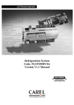
INSTALLATION & OPERATING MANUAL GRAVITAS SABRE SERIES MODULAR INVERTER SYSTEM WWW.UNIPOWERTELECOM.COM Manual No. SABRE-4 11/27/07 sabre-man © 2007 UNIPOWER Corp. All Rights Reserved UNIPOWER Telecom, Division of UNIPOWER Corporation NORTH AMERICA • 3900 Coral Ridge Drive, Coral Springs, Florida 33065, USA • Tel: +1 954-346-2442 • Fax: +1 954-340-7901 • [email protected] EUROPE • Parkland Business Centre, Chartwell Road, Lancing BN15 8UE, ENGLAND • Tel: +44(0)1903 768200 • Fax: +44(0)1903 764540 • [email protected] GRAVITAS SABRE SERIES INSTALLATION &OPERATING MANUAL Manual No. SABRE-4 Page 2 11/27/07 sabre-man GRAVITAS SABRE SERIES INSTALLATION &OPERATING MANUAL Contents 1 System Information & Description .............................................................................................................................. 4 1.1 Inverter Module Specification........................................................................................................................... 4 1.1.1 Electrical Specification ............................................................................................................................. 4 1.1.2 Environmental Specification..................................................................................................................... 5 1.1.3 Mechanical Specification .......................................................................................................................... 6 1.2 STS Module Specification.................................................................................................................................. 9 1.2.1 Electrical features...................................................................................................................................... 9 1.2.2 STS Module Environmental Specification.............................................................................................. 22 1.2.3 STS Mechanical Specification ................................................................................................................ 22 1.3 Maintenance Bypass Switch Module Specification........................................................................................ 25 1.3.1 Electrical Specification ........................................................................................................................... 25 1.4. Controller Module Specification .................................................................................................................... 26 1.4.1 Input Specification .................................................................................................................................. 26 1.4.2 Human Interface Specification................................................................................................................ 26 1.4.3 Alarm Mode ............................................................................................................................................ 26 1.4.4 Communications Interfaces..................................................................................................................... 27 1.4.5 Mechanical Specification ........................................................................................................................ 28 1.4.6 Environmental Specification................................................................................................................... 28 2. System Features ......................................................................................................................................................... 29 2.1 Principal of Operation ..................................................................................................................................... 32 2.2 Typical System Configurations ....................................................................................................................... 32 3 Electrical Connections ................................................................................................................................................... 34 3.1 Description ........................................................................................................................................................ 34 3.2 DC Input............................................................................................................................................................ 35 3.3 AC Input............................................................................................................................................................ 35 3.4 AC Output......................................................................................................................................................... 35 3.5 DC Input for controller.................................................................................................................................... 38 3.6 Internal Communications connections ........................................................................................................... 38 3.7 External Communications Connections ......................................................................................................... 38 3.7.1 Communications Connections of the Controller ..................................................................................... 38 3.7.2 Dry contact Alarm Settings ..................................................................................................................... 39 4 Mechanical Installation.................................................................................................................................................. 41 4.1 Inverter Shelf & Inverter Module Installation and Removal....................................................................... 41 4.1.1 Inverter shelf Installation ........................................................................................................................ 41 4.1.2 Inverter shelf Removal............................................................................................................................ 41 4.1.3 Inverter Module Installation.................................................................................................................... 42 4.1.4 Inverter Module Removal ....................................................................................................................... 42 4.2 STS/Controller Shelf, STS Module & Controller Module Installation and Removal ................................ 43 4.2.1 STS/Controller shelf installation............................................................................................................. 43 4.2.2 STS/Controller shelf removal ................................................................................................................. 43 4.2.3 Communication Interface module Installation ........................................................................................ 44 4.2.4 Communication Interface module Removal............................................................................................ 44 4.2.5 STS Module Installation ......................................................................................................................... 44 4.2.6 STS Module Removal............................................................................................................................. 45 4.3 Controller Installation and Removal .............................................................................................................. 45 4.3.1 Controller Module Installation ................................................................................................................ 45 4.3.2 Controller Module Removal ................................................................................................................... 46 4.4 Inverter system Rear Installation and Removal ............................................................................................ 46 4.4.1 Inverter system Rear Installation............................................................................................................. 46 4.4.2 Inverter system Rear Removal ................................................................................................................ 47 5 Operation...................................................................................................................................................................... 48 5.1 Start up Operation ........................................................................................................................................... 48 5.2 Operation in Running with a Controller Installed ........................................................................................ 48 5.2.1 Status & Settings for the System............................................................................................................. 48 6 Maintenance, Adjustments and Troubleshooting ........................................................................................................... 51 Manual No. SABRE-4 Page 3 11/27/07 sabre-man GRAVITAS SABRE SERIES INSTALLATION &OPERATING MANUAL 1 System Information & Description The UNIPOWER Telecom SABRE Series Inverter System utilizes Digital Signal Processing controlled, 1000/1500VA, modular inverters, contained in a 19/23inch shelf, to supply 120/230VAC to telecom equipments when 48VDC (nominal) is supplied. The controller, allows the user to monitor real-time system status such as output voltage, output current, alarm status, and also allows system parameter settings to quickly be changed with the touch of a few keys. The STS (Static Transfer Switch) increases system reliability by automatically switching between the inverter output and the AC utility supply, providing protection against interruptions caused by system failure. The STS can be programmed to provide the Utility supply to the load under normal conditions and switch to the inverters as a back-up in the event of utility failure; or alternatively the inverters can be the normal source of power to the load, using the Utility as a backup. This programmability of primary and backup source allows the SABRE system to be used in many different applications including traditional Telecom and ‘Green Energy’ such as solar or wind generation. The MBS (Maintenance Bypass Switch) consists of a mechanical switch providing free maintenance for the safe removal of the STS module without interruption of power to the load. The inverter modules are fully hot-swappable and operate automatically in an N+1 redundant configuration. The SABRE Series Inverter System can accommodate up to 12 inverter modules for an output capacity up to 50Amps when employing the STS while an output capacity of 100A is possible without the STS. Up to 12 shelves can be connected in parallel to supply AC power. The system can be installed in both 19-inch and 23-inch cabinet configurations. 1.1 Inverter Module Specification 1.1.1 Electrical Specification Input Item Nominal voltage Operating range Under voltage warning threshold Under voltage threshold Over voltage warning threshold Over voltage threshold Isolation AC-DC Inrush current Isolation DC-enclosure Input protection Psophometric noise voltage Reflected Psophometric noise current Reflected relative band wide current noise Wide Band Noise Peak to peak noise Manual No. SABRE-4 Specification 48Vdc 40.5Vdc ~ 58.0Vdc 45Vdc 40Vdc 58.0Vdc 60Vdc Reinforced isolation (Pri-Sec) 4242Vdc/1min <2*Irated 707Vdc/1min Remarks IEC62040-3(1999) (Varistors and filter capacitor removed) Reverse Polarity Protection 1.0mV ITU-T O.41 (16.66~6000Hz) According to YD /T 777-2006 less than 1% According to YD/T 777~2006 less than 10%(0-2Mhz) <1.0mVpsof (25Hz~5KHz) <20mVrms (25Hz~20KHz) 150mV up to 100MHz Page 4 11/27/07 sabre-man GRAVITAS SABRE SERIES INSTALLATION &OPERATING MANUAL Output Item Waveform Output power Power factor Nominal output voltage Output voltage variation Output Frequency Frequency variation Crest factor THD Capacitive/inductive load Efficiency Current limitation Isolation AC-enclosure Surge protection Dynamic response Over load protection Control Load sharing Display Status/alarm information Communication (internal to system) Runtime info. Useful life Specification Pure sine wave 1000 VA/800W or 1500VA/1200W 0.8 110/115/120VAC or 208/220/230/240VAC Max ±2% 50/60Hz Max ±0.5% 3:1 <3%, linear load <5%, non-linear load -0.8 to +0.8 without exceeding permissible distortion for resistive load Min 88% at rated load Electronic current limitation at overloads and short circuits. Basic isolation (Pri-Gnd) 2121Vdc/1min EN61000-4-5. Telcordia GR-1089 Core ANSI C62.41-IEEE, STD 587-1980 <±10% 2*Inom ,5S max 1.5*Inom, 10S max 1.25*Inom temperature controlled Inom = 1000VA/output voltage Remarks Model Dependent Model Dependent Programmable <5% 3 LEDs installed at the front of faceplate Inverter failure (dry-contact) Remote info Inverter failure/Overload alarm/Low voltage disconnect alarm/ Fan Failure alarm/Thermal derating info/Power output/Input voltage/Output voltage/ Output current/Output frequency/Low input voltage shut off/Product info data Remote On/Off function CAN Bus Handled through a maintenance feature in the controller 12 years 1.1.2 Environmental Specification Item Operation temperature Storage Temperature Noise Safety EMC Manual No. SABRE-4 Specification -20°C(-4°F) to 70°C(158°F), absolute maximum -5°C(23°F) to 50°C(122°F) with full performance -40°C(-40°F) to 85°C(185°F) 55dB ETS 300 753, class 3.1 UL60950-1/EN60950-1/IEC60950-1 EN300 386:2001. Class B compliance Page 5 11/27/07 sabre-man GRAVITAS SABRE SERIES INSTALLATION &OPERATING MANUAL 1.1.3 Mechanical Specification Items Specification Depth: 10.63” (270mm) Height, body: 1.59” (40.5mm) Height, front panel: 1.72” (43.8mm) (1U) Width: 8.46” (215mm) (5U) Inverter module can be changed in a live system No wires need to be connected or tools required for installation of inverter into shelf Smart control, easy replacement 50A with STS, 100A without STS, see below. Module Dimensions Hot swappable Hot pluggable Force cooling # inverter modules in parallel Module # 1 2 3 4 INV1048H (1000VA/230 Output) Module current = 4.4A INV1048 (1000VA/120 Output) Module current = 8.3A INV1548H (1500VA/230 Output) Module current = 6.5A INV1548 (1500VA/120 Output) Module current = 12.5A Manual No. SABRE-4 SABRE Series Inverter Parallel Capacity With 50A STS Without STS # Units Algorithm # Units Algorithm 12 1000VA/230VAC=4.4A 50A/4.4A=11.36 units 24 Software protocol control 6 1000VA/120VAC=8.3A 50A/8.3A=6.02 units 12 System capacity limit 100A 100A/8.3=12 units 8 1500VA/230VAC=6.52A 50A/4.4A=7.66 units 15 System capacity limit 100A 100A/6.52=15.3 units 4 1500VA/120VAC=12.5A 50A/12.5A=4.0 units 8 System capacity limit 100A 100A/12.5=8.00 units Page 6 11/27/07 sabre-man GRAVITAS SABRE SERIES INSTALLATION &OPERATING MANUAL Fault LED Warning LED Power On LED Lock Switch Figure 1 Inverter module dimensions (mm) Manual No. SABRE-4 Page 7 11/27/07 sabre-man GRAVITAS SABRE SERIES INSTALLATION &OPERATING MANUAL BAT- in: DC Cathode BAT+ in: DC Anode CN11: Not used UC3: AC Neutral out UC4: AC Ground UC5: AC Line out CN9 : Power Connector to Controller CN20/CN21 : Inter-Parallel Connectors CN7: COM/SYNC port with STS module CN13: Not used CN8 : CAN COM port with controller module Figure 2 Inverter shelf Gimensions (mm) JP2 : Matching resistor selector Jumper installed positions 1-2 for single inverter shelf installations, removed or installed positions 2-3 for multiple inverter shelf installations. Manual No. SABRE-4 Page 8 11/27/07 sabre-man GRAVITAS SABRE SERIES INSTALLATION &OPERATING MANUAL 1.2 STS Module Specification 1.2.1 Electrical features 1.2.1.1 Input Item AC voltage range Specification 110/115/120 VAC: from89 to 138 VAC 208/220/230/240 VAC: 176 to 276 VAC Adjustable using controller: 220 to 240 VAC for 208 VAC systems 233 to 252 VAC for 220 VAC systems 244 to 264 VAC for 230 VAC systems 254 to 276 VAC for 240 VAC systems Over voltage threshold 117 to127 VAC for 110 VAC systems 122 to 132 VAC for 115 VAC systems 127 to 138 VAC for 120 ac systems Under voltage threshold Adjustable using controller: 176 to 198VAC for 208 VAC systems 176 to 209VAC for 220 VAC systems 185 to 218VAC for 230 VAC systems 193 to 228VAC for 240 VAC systems Redundant power supply design 89 to 105VAC for 110 VAC systems 93 to 110VAC for 115 VAC systems 100 to 114VAC for 120 VAC systems Startup power-on by priority source or alternative Note: The over/under voltage settings are managed by the controller. If there is no controller installed, the STS module will adopt the widest range to set over/under voltage in order to guarantee its performance. For 110/115/120 VAC systems, the range is from 89VAC(under voltage point) to 138VAC(over voltage point); for 208/220/230/240 VAC systems, the range is from 176VAC(under voltage point) to 276VAC(over voltage point). However, once the STS module is set by the controller, it will retain the setting permanently so a controller can be installed to alter these settings and then removed if not required. 1.2.1.2 Output Item Waveform Nominal output voltage Permissible frequency area Specification Sinusoidal Same as mains AC or the output of inverter modules Max. ±2.5% (Synchronize area of Inverter) Transfer time Rated current Operation methods Typical 1/4cycle 50A Inverter priority or Utilitypriority Manual No. SABRE-4 Page 9 Remarks ±1.5Hz for 60Hz Inverter ±1.25Hz for 50Hz Inverter All voltage settings Programmable 11/27/07 sabre-man GRAVITAS SABRE SERIES INSTALLATION &OPERATING MANUAL 1.2.1.3 Alarm Information Item STS Alarms Information Specification CAN communication failure Back-feed relay open SCR1 short circuit SCR2 short circuit Output short Over load Over temperature Mains unavailable Inv unavailable Output abnormal STS fan failure MBS position error EEPROM fault 1.2.1.4 Interface Item Human Interface LED Indicator Communication Interface Communication Manual No. SABRE-4 Specification 3-LED installed at the front of faceplate Communicates with controller and Inverter modules through CAN Bus interface Page 10 11/27/07 sabre-man GRAVITAS SABRE SERIES INSTALLATION &OPERATING MANUAL 1.2.1.5 Operating status for the various positions of the MBS The operation mode of STS is closely linked with the position of MBS. The MBS has two main contacts and three auxiliary contacts, signals generated by the three auxiliary contacts are passed to STS for position detection. Once an auxiliary contact is closed, the signal is logic 0, in reverse it will be logic 1. The combination of logic 0 and 1 can produce five valid position statuses. Position status of MBS SW1/SW2/SW3 are the logic level signals detected by STS, the five valid status conditions are as follows: MBS Position P1 Mode Define Contacts Signals SW1 0 SW2 1 SW3 1 Mains Bypass (MBP) Postural Plot M SS NORM IB P MBP P2 0 0 1 Inverter Maintenance (MSS) M SS NORM 0 0 0 Normal Operation (NORM) M SS NORM 1 0 0 Mains Maintenance (ISS) M SS NORM 1 1 0 Inverter Bypass (IBP) M SS M BP Invalid 1 0 1 0 1 1 IS S IB P M BP P5 IS S IB P MBP P4 IS S IB P M BP P3 IS S NORM IS S IB P Reserved 1 0 1 Figure 3 MBS positions (0 = Low, 1 = High) The STS will continuously detect the position of the MBS in order to decide the transferring action between different modes. The STS will continuously detect whether the position of the MBS is valid. If the status is invalid, the STS will consider the MBS faulty, it won’t enter any operation mode, and the red LED will blink at 5Hz, at the same time the “MBS abnormal” alarm will be sent to the controller, this phenomenon won’t disappear until the detection signal becomes normal. If the MBS is changed when the STS is running at one of the five valid positions, and this change happens between two adjacent positions, then the STS will transfer to a different mode based on current status, otherwise the STS won’t take any action. For example, if the MBS is at P3, the STS will take action when the MBS is turned to P2 or P4. Note: Be sure not to change the MBS position immediately after the STS is inserted into the rack; wait at least 5 seconds if you want to change it and ensure that the MBS remains in each consecutive position for at least 1 second at one position. Manual No. SABRE-4 Page 11 11/27/07 sabre-man GRAVITAS SABRE SERIES INSTALLATION &OPERATING MANUAL 1.2.1.6 Operation principal of STS The operation of the STS at each valid state is described below: MBS Status Schematic operation principle of STS Description 0%6 0DL Q &RQW DFW Mains Bypass(MBP): 6&5 %DFNI HHG 5HO D\ 0DL QV %\SDVV 5HO D\ Mains Bypass (P1) /RDG , QYHUW HU 6&5 Load is powered through the MBS by the Mains AC STS does not provide any load power, and can be removed from the system STS can be removed from the system MBS can only be switched from P1 to P2 position SCR2 open, SCR1 and Back-feed Relay closed 0%6 0DL Q &RQW DFW 0%6 0DL Q &RQW DFW Inverter Maintenance(MSS): %DFNI HHG 5HO D\ 6&5 0DL QV Inverter Maintenance (P2) %\SDVV 5HO D\ /RDG , QYHUW HU 6&5 Mains AC powers the load through the static switch Inverters are on, but do not provide any load power Inverters can be removed from the system, but the static switch cannot MBS can be switched from P2 to P1 and P3 position SCR2 open, SCR1 and Back-feed Relay closed When SCR2 is short, the STS will stay in off-line mode 0%6 0DL Q &RQW DFW Manual No. SABRE-4 Page 12 11/27/07 sabre-man GRAVITAS SABRE SERIES INSTALLATION &OPERATING MANUAL MBS Status Schematic operation principle of STS Description Normal Operation(NORM) MBS Main Contact1 Mains priority: SCR1 Backfeed Relay Mains Bypass Relay Load Normal Operation (P3) Inverter SCR2 MBS Main Contact2 Mains AC powers the load through the static switch MBS can be switched from P3 to P2 and P4 position SCR2 open, SCR1 and Back-feed Relay closed When the mains voltage or frequency is abnormal, and the inverter is normal, the STS transfers to on-line mode When SCR2 is short, the STS will keep the off-line mode Normal Operation(NORM) MBS Main Contact1 Inverter priority: Backfeed Relay SCR1 Mains Bypass Relay Normal Operation (P3) Load Inverter SCR2 MBS Main Contact2 Manual No. SABRE-4 Page 13 Inverters power the load through the STS MBS can be switched from P3 to P2 and P4 position SCR1 open, SCR2 and Back-feed Relay closed When the Inverter’s voltage or frequency is abnormal, and the mains is normal, the STS transfers to off-line mode When SCR1 is short, the STS will keep the on-line mode, and the Back-feed relay will open 11/27/07 sabre-man GRAVITAS SABRE SERIES INSTALLATION &OPERATING MANUAL MBS Status Schematic operation principle of STS Description MBS Main Contact1 Mains Maintenance(ISS): SCR1 Mains Mains Maintenance (P4) Backfeed Relay Bypass Relay Load Inverter SCR2 Inverters power the load through the STS AC mains is disconnected from the system, and the STS cannot be removed from the system MBS can be switched from P4 to P3 and P5 Back-feed Relay and SCR1 open, and SCR2 closed MBS Main Contact2 MBS Main Contact1 Inverter Bypass(IBP): SCR1 Mains Backfeed Relay Bypass Relay Inverter Bypass (P5) Load Inverter SCR2 MBS Main Contact2 Load is powered through the MBS by the inverters. The STS does not provide any load power, and it can be removed from the system STS can be removed from the system MBS can only be switched from P5 to P4 position Back-feed Relay and SCR1 open, and SCR2 closed Figure 4 STS operation principle Manual No. SABRE-4 Page 14 11/27/07 sabre-man GRAVITAS SABRE SERIES INSTALLATION &OPERATING MANUAL 1.2.1.7 Voltage and frequency mode The STS has two inputs and one output. The two inputs are from Mains Utility and Inverters; the output is the system output. The STS will continuously detect Mains voltage and Inverter voltage in order to decide the system’s supply mode. If both Mains and Inverters are normal, the Mains has priority to decide the operation status of the system. In other words, the STS will firstly consider the Mains status to decide the system’s running voltage and frequency. Following confirmation of the voltage and frequency, the over/under voltage and over/under frequency are set as follows: Over/under voltage window 120VAC 110V/115V/120V 138VAC 134VAC 89VAC 93VAC Default Voltage Over Volt Under Volt Activate Recovery Activate Recovery 240VAC 208V/220V/230V/240V 276VAC 268VAC 176VAC 184VAC Over/under frequency window System frequency 60Hz 61.5Hz 61.2Hz 58.5Hz 58.8Hz Frequency high threshold Frequency high back Frequency low threshold Frequency low back 50Hz 51.25Hz 51Hz 48.75Hz 49Hz Voltage Transfer Window The STS will transfer to the auxiliary source if the priority input voltage exceeds a preset value, the over voltage and under voltage limits are as follows: Adjustable range Over volt Under volt Adjustable range Default value Adjustable range Default value Manual No. SABRE-4 110V 117~127 127 89~105 89 120VAC 115V 122~132 132 93~110 93 120V 127~138 138 100~114 100 Page 15 208V 220~240 240 176~198 176 240VAC 220V 230V 233~252 244~264 252 264 176~209 185~218 176 185 240V 254~276 276 193~228 193 11/27/07 sabre-man GRAVITAS SABRE SERIES INSTALLATION &OPERATING MANUAL 1.2.1.8 Fan control 1.2.1.8.1 Fan speed control The speed of STS fans is decided by the output current and the NTC temperature, with the NTC temperature taking priority. When the temperature of the NTC is above 80ºC, the fan will operate at maximum speed according to the valid fan number, otherwise, the fan will operate according to the load current. The following tables show the relationship between the fan speed and load current. In normal circumstances, where both fans are running, the speed is based on definition -2 shown below. When one of the two fans is locked, the speed is based on definition -1. If both fans are locked for more than 2 minutes the STS will transfer to Inverter bypass mode and the STS module will shut down. One fan---- definition-1 Load Temperature of NTC Speed level Load < 25% 25% Load < 50% 75% < Load 50% Load > 75% Any load <80ഒ >=80ഒ Speed2 Speed3 Speed4 Speed5 Speed6(full speed) Load Temperature of NTC Speed level Any Load <80ഒ Any Load >=80ഒ Speed1(the lowest speed᧥ Speed5 Two fans---- definition-2 1.2.1.9 Over temperature protection On-line Mode (Inverters Providing Power) When the temperature is over 85ºC, the STS will power the load through the bypass relay, and SCR2 will be open. If the temperature reaches 90ºC, the bypass relay will open, and the load will be disconnected until the STS is restarted. The system will re-establish power through the inverter with SCR2 closed and the relay open, when the temperature is under 65ºC and at least one fan is running. The STS will then return to normal mode. Off-line Mode (Utility/Mains Providing Power) When the temperature is over 85ºC, the STS will transfer to on-line mode if the Inverter is normal, then the over temperature protection is the same as on-line mode. If the temperature is less than 65ºC and at least one fan is running, the system will re-establish the power through the inverter with SCR2 closed and the relay open and the system will return to off-line mode. x x x Inverter bypass: 85ºC Inverter bypass back: 65ºC Temperature protection: 90ºC Manual No. SABRE-4 Page 16 11/27/07 sabre-man GRAVITAS SABRE SERIES INSTALLATION &OPERATING MANUAL 1.2.1.9.1 Off-line mode Figure 6 Off-line mode relay bypass transfer Manual No. SABRE-4 Page 17 11/27/07 sabre-man GRAVITAS SABRE SERIES INSTALLATION &OPERATING MANUAL 1.2.1.9.2 On-line mode Figure 7 On-line mode relay bypass transfer Manual No. SABRE-4 Page 18 11/27/07 sabre-man GRAVITAS SABRE SERIES INSTALLATION &OPERATING MANUAL 1.2.1.10 SCR short protection/Back-feed protection 1.2.1.10.1 On-line mode The SCR1 on the mains side will be detected when the STS operates in on-line mode. If SCR1 is short, the back-feed relay will be open, and the system continues to power the load from the inverters. At this time, “SCR1 short alarm” will be sent to the controller via the CAN bus. B a ckfe e d re la y clo se d S C R 1 is n o rm a l B ackfee d R ela y SCR1 M a in s B yp a ss R e la y Load In ve rte r SCR2 In ve rte r p o w e r th e lo a d B a ckfe e d re la y o p e n SCR1 sh o rt B ackfee d R ela y SCR1 M a in s B yp a ss R e la y Load In ve rte r SCR2 In ve rte r p o w e r th e lo a d Figure 8 SCR1 short in on-line mode Manual No. SABRE-4 Page 19 11/27/07 sabre-man GRAVITAS SABRE SERIES INSTALLATION &OPERATING MANUAL 1.2.1.10.2 Off-line mode The SCR2 that is on the inverter side will be detected when the STS operates in off-line mode. When SCR2 is short, the system will continue to power the load from the Utility. An “SCR2 short alarm” will be sent to the controller via the CAN bus. B ackfeed relay closed B ackfeed R elay SC R 1 M ains L oad B ypass R elay Inverter SC R 2 SC R 2 is norm al M ains pow er the load B ackfeed relay closed B ackfeed R elay SC R 1 M ains L oad B ypass R elay Inverter SC R 2 Inverter pow er the load F ault SCR2 short Figure 9 SCR2 short in off-line mode Manual No. SABRE-4 Page 20 11/27/07 sabre-man GRAVITAS SABRE SERIES INSTALLATION &OPERATING MANUAL 1.2.1.11 Overload/output short circuit protection 1.2.1.11.1 Overload protection <1> Method one When the STS is operating in either On-line or Off-line mode, the load current will be calculated in the firmware automatically. This calculation will be used in the overload protection function. With 20S time of 120% overload, or 5S time of 160% overload, the system will cease to provide output power, and the static switch will send an “Overload” alarm to the controller. (Note: The STS will need to have all power recycled to restart from this condition). <2> Method two The STS will estimate the load capability of the system based on the number of installed inverters reported by the controller. For the INV1048 the definition of rated power in VA is “inverter number x 1000VA”, with rated active power “VA x 0.8”. For the INV1548 the definition of rated power in VA is “inverter number x 1500VA”, with rated active power “VA x 0.8”. When the Utility has priority the STS operates in off-line mode. With a change of priority to the Inverter the STS will estimate the load capability of the Inverters to decide whether to transfer to on-line mode. If the current load exceeds the load capability of the Inverters the STS won’t transfer to on-line mode, otherwise it will transfer to on-line mode approximately 6 seconds later. As an exception, the STS will immediately transfer to on-line mode without estimating the load capability of the Inverters when the utility voltage or frequency is abnormal. 1.2.1.11.2 Output short protection Based on the different priorities, output short protection has different methods to deal with each situation. <1> Mains priority If the Inverter is operating normally when the output short happens the STS will transfer to Inverter mode, then “Output short protection” will be sent to controller and finally the STS will transfer to fault mode If the Inverter is faulty or off when the output short happens the STS will shut off the output and an “Output short protection” message will be sent to controller (if present). <2> Inverter priority If the Mains is normal when the output short happens the STS will transfer to Mains mode, and then an “Output short protection” message will be sent to the controller. If the Mains is abnormal or not present when the output short happens the STS will send an “Output short protection” message and then transfer fault mode. Note᧶Damage to the STS will occur if the short current exceeds 2400A. Manual No. SABRE-4 Page 21 11/27/07 sabre-man GRAVITAS SABRE SERIES INSTALLATION &OPERATING MANUAL 1.2.2 STS Module Environmental Specification Item Noise Operating temperature Storage temperature Operating humidity Operating Attitude Specification 55 dB, ETS 300 753, class 3.1 -20°C (-4°F) to 70°C (158°F) -5°C (23°F) to 50°C (122°F) with full performance -40°C (-40°F) to 85°C (185°F) 90% RH (non condensing) 1500m 1.2.3 STS Mechanical Specification Item Dimensions W x H x D Weight Hot swappable Mounting method Maintenance Bypass Switch (MBS) Cooling Specification 8.46” (215mm) x 1.59” (40.5mm) x 10.63” (270mm) 4.4lbs (2kg) When MBS at Mains Bypass or Inverter Bypass position Plug-in type module The STS module used in combination with the mechanical Maintenance Bypass Switch module allows voltage free system maintenance. A mechanical interlock with the STS module ensures that the STS module cannot be removed without the MBS being activated. 2 Fans - easy replacement Remarks Only when MBS installed MBS module must be installed immediately above the STS module Manual No. SABRE-4 Page 22 11/27/07 sabre-man GRAVITAS SABRE SERIES INSTALLATION &OPERATING MANUAL Fault LED Warning LED Power On LED Lock Switch Figure 11 STS module dimensions (mm) Manual No. SABRE-4 Page 23 11/27/07 sabre-man GRAVITAS SABRE SERIES INSTALLATION &OPERATING MANUAL CN1:Connector to UC5: MBS UC4: AC Input Cathode AC Output Cathode CN12 : Power CN3 : CN4: Connector of CAN COM port other Bat Control (future option) controller module Controller CN2: Signal Port Between STS & Inverter UC3: AC Neutral UC2: AC Ground UC1: AC Line CN7~CN11: Dry Contact CN2,CN6: CN13: RS232 RS485 Figure 12 STS/Controller shelf dimensions (mm) Manual No. SABRE-4 Page 24 11/27/07 sabre-man GRAVITAS SABRE SERIES INSTALLATION &OPERATING MANUAL 1.3 Maintenance Bypass Switch Module Specification 1.3.1 Electrical Specification Item AC Input Selectable Input Frequency Rating Power Type (mechanical switch, 5 positions) Specification 110/115/120 VAC or 208/220/230/240VAC 50/60 Hz 6kW for 110/115/120 VAC 12kW for 208/220/230/240 VAC MBP (mains bypass) Position The load is powered through the maintenance bypass switch by the mains AC. The STS can be removed from the system. ISS (inverter static switch) Inverters are ON, but do not provide any load power. Inverter tests can be made. Norm Position The load is powered through the STS by the Inverters. MSS (mains static switch) The mains AC is disconnected from the system. This is achieved by opening the back-feed contactor. IBS (inverter bypass) The load is powered through the MBS by the Inverters. The STS can be removed from the system. Figure 14 MBS+PDU shelf dimensions (mm) Manual No. SABRE-4 Page 25 11/27/07 sabre-man GRAVITAS SABRE SERIES INSTALLATION &OPERATING MANUAL 1.4. Controller Module Specification 1.4.1 Input Specification Item Nominal voltage Operating range Over Current Protection Specification Remarks Specification Resolution :Line * Array: 4 * 16 Green LED Red LED Yellow LED Enter Esc PgUp PgDn AlarmÆ Beep continuously Remarks 48Vdc 30Vdc -72Vdc 2A Fuse 1.4.2 Human Interface Specification Item LCD LED Indicator Function Keys Buzzer Press ENTER to defeat 1.4.3 Alarm Mode Alarm Type Inverter Manual No. SABRE-4 Alarm Name Inverter fault Inverter Level Major Observe Over-loading Inverter Major Fan fault Inverter power limit Inverter input abnormal Inverter shut down due to low input volt Inverter not respond Bus volt over the maximal level Bus volt under the minimal level Bus Soft Start Fail Inverter Output Short Inverter output volt low Inverter output volt high Inverter Temperature High Inverter negative power protection Sync Pulse Fault EPO Inverter soft start fail Inverter EEPROM fault Reserved Major Major Major Critical Critical Critical Critical Critical Critical Critical Critical Critical Critical Critical Critical Major Page 26 11/27/07 sabre-man GRAVITAS SABRE SERIES INSTALLATION &OPERATING MANUAL Alarm Type STS Controller Alarm Name Bypass unavailable STS priority Alarm Back-feed relay open SCR1 short circuit SCR2 short circuit STS running in fault mode Level Major Major Major Critical Critical Critical STS fan fault EEPROM fault STS operation mode alarm Inverter unavailable Mains unavailable Output over load Output short circuit Inverter capacity limit Inverter bypass mode STS temperature high MBS in abnormal position Control power fail STS not respond Reserved Bat Volt Low Controller temperature High Controller EEPROM fault Bat voltage high Controller CAN bus off Reserved Major Major Major Major Major Major Critical Major Critical Major Critical Critical Critical Critical Critical Major Critical Critical Note :The relationship between the alarm level and controller indication: Controller indication Yellow Led On Red Led On Red Led On and Buzzer Beeping continuously Alarm Level Observe Major Critical Remark 1.4.4 Communications Interfaces Item RS-232 × 1 CAN Bus × 1 RS-485 × 2 SNMP × 1 Dry Contact × 5 USB × 1 Manual No. SABRE-4 Specification Communicates with PC Communicates with Inverter and STS Communicates with supervision / Battery supervision Communicates with PC Communicates with external Monitor Communicates with PC Page 27 Remarks 11/27/07 sabre-man GRAVITAS SABRE SERIES INSTALLATION &OPERATING MANUAL 1.4.5 Mechanical Specification Item Controller Dimensions WxHxD Weight Cooling & Ventilation Specification 2U x 1U x 6U (without optional interfaces) 3.15” (80mm) x 1.59” (40.5mm) x 10.63” (270mm) 2.2lbs (1kg) Natural cooling Remarks Installed in Controller/STS shelf unit. Power On LED Function Keys Warning LED Fault LED LCD Display Figure 15 Controller module dimensions (mm) 1.4.6 Environmental Specification Item Operating temperature Storage temperature Operating humidity Operating Altitude Manual No. SABRE-4 Specification -20°C (-4°F) to 70°C (158°F) -40°C (-40°F) to 85°C (185°F) 90% RH (no condensing) 2000m Page 28 11/27/07 sabre-man GRAVITAS SABRE SERIES INSTALLATION &OPERATING MANUAL 2. System Features Compact Design Inverter power density up to 5.24W/in³ (0.32W/cm3) for 1000VA, 7.87W/in³ (0.48 W/cm3) for 1500VA. Modular design System output capacity scaleable according to requirements. Parallel operation and N+1 redundancy Inverters operate in true N+1 redundant mode with load sharing. Hot swappable Inverter modules can be swapped in a live system. Reliability with optional STS module and MBS module The STS increases system reliability by automatically switching between the Inverter output and the AC Utility, providing protection against interruptions caused by system or AC utility failure. The MBS consists of a mechanical switch providing free maintenance for the safe removal of the STS module without load power interruptions. LCD & Led Indicator The Controller LCD has two functions. It can display the status of the system and each module and it can be used to set the parameters of the system and the individual modules. The LEDs indicate individual module status as described in the following table. The LEDs are either ON, OFF or flashing at one of 6 rates: Flash 1 – once per second with 50% duty Flash 2 – once per second with 10% duty Flash 3 – 2 times per second with 50% duty Flash 4 – 4 times per second with 50% duty Flash 5 – 4 times per second with 20% duty Flash 6 – 5 times per second with 50% duty Inverter Module LED Display Priority Green LED Solid Priority LED Signal Status Inverter operating normally Flash 1 Inverter is being interrogated by the controller Flash 2 One of the status as follows: 1) Power On Sequence. Details refer to note. 2) Shut down remotely. Yellow LED Flash 2 LED Signal Status Power On Details refer to note. Over Load Solid (Load percent > 100%) Flash 4 DC input abnormal ( Vin<=45V or Vin>=58 V) Flash 5 1S 1S Inverter shut down due to super low /super high input (Vin<=VLVSD or Vin>=VHVSD) Manual No. SABRE-4 Page 29 11/27/07 sabre-man GRAVITAS SABRE SERIES INSTALLATION &OPERATING MANUAL Priority Low High Red LED Flash 1 LED Signal Status One of the alarms as follows: 1) EEPROM Fault; Inverter module cannot operate in parallel mode system, however, it can work in single mode system 2) Fan Fault Fan failed in operation One of the alarms as follows: 1) Internal DC Bus Over /Under/ Unbalance/soft start fail; The inverter will shutdown. 2) Over Temperature. The inverter will shut down. Flash 4 In both cases Recycle the power or remove and reinsert the module to restart. One of the alarms as follows: 1) Input reverse polarity; The DC input voltage polarity is reversed. 2) Inverter output short circuit; When a short circuit occurs the inverter will shut down. 3) Abnormal output voltage; The inverter will shut down when output voltage is out of operating voltage range. 4)Negative Power Protection The inverter will shut down. 5) Overload fault. When the time of overload exceeds the defined time, the inverter will shut down. Solid In all cases recycle the power or remove and reinsert the module to restart. Notes: Power On Sequence: When the inverter is in “Power On” mode, the green led and the yellow LED are blink synchronously. Overload and overload fault: When the overload fault alarm occurs the yellow and red LEDs turn on at the same time. When an overload alarm occurs only the yellow LED turns on. Priority: If more than one warning exists at the same time, then the LED will display the highest priority condition. Manual No. SABRE-4 Page 30 11/27/07 sabre-man GRAVITAS SABRE SERIES INSTALLATION &OPERATING MANUAL STS Module LED Display Priority Green LED Solid Flash 1 LED Signal Status STS operating normally Running mode not according to the setting priority. For example, STS operating in off-line mode, but the priority is set to on-line. STS operating in inverter bypass mode LED Signal Status Mains or Inverter abnormal If the status of the green LED is the same as the yellow LED, then the STS is in Inverter bypass mode, otherwise the Back-feed relay open STS Output abnormal LED Signal Status Fan lock or Can communication fail or EEPROM fault SCR short or auxiliary power supply fault MBS position abnormal Flash 3 Priority Low Yellow LED Solid Flash 3 Flash 6 High Priority Low Red LED Flash 1 Flash 3 Flash 6 STS Fault mode, maybe overload or over temperature or output short Solid High Note: If more than one warning exists at the same time, then the LEDs will display the highest priority condition. Manual No. SABRE-4 Page 31 11/27/07 sabre-man GRAVITAS SABRE SERIES INSTALLATION &OPERATING MANUAL 2.1 Principal of Operation Rectifier System Inverter System Telecom Equipment Static Transfer Switch AC . . . . . DC Distribution . . . . . Telecom Equipment AC Distribution Telecom Equipment Telecom Equipment Telecom Equipment Telecom Equipment Low Voltage Disconnect Battery Controller Figure 16 Telecom power system The inverter system accepts 40.5 to 58VDC for normal operation; however it requires an input of at least 45VDC to start. This voltage is applied to the system through the BAT+ and BAT– input bus connections. The system will supply nominal 120VAC or 230VAC to the loads. 2.2 Typical System Configurations Configuration 1: •Controller / Communications •STS Module •Inverter Modules •AC Distribution Unit •MBS Module Manual No. SABRE-4 Page 32 11/27/07 sabre-man GRAVITAS SABRE SERIES INSTALLATION &OPERATING MANUAL Configuration 2: •Controller / Communications •Inverter Modules Configuration 3: •STS Module •Inverter Modules •AC Distribution Unit •MBS Module Configuration 4: •Inverter Modules Figure17 Typical system configurations Manual No. SABRE-4 Page 33 11/27/07 sabre-man GRAVITAS SABRE SERIES INSTALLATION &OPERATING MANUAL 3 Electrical Connections 3.1 Description This chapter provides details for the installer for the electrical connections when installing the Gravitas SABRE Series inverter system. Before making any electrical connections refer to Figure 20 below. AC Input Terminal AC Output Terminal Output Socket STS Output Line DC Input cable for controller (3 pin) STS Mains Line Communication Interface Bat- bus bar Dry Contact Of System Bat+ bus bar CAN Bus connection for controller between other modules (2 pin) Parallel Signal Connector Inverter Output Line Communication cable for inverter and STS Inverter Output Ground Inverter Output Neutral Figure 20 Electrical connections of inverter system Figure 21 System block diagram Manual No. SABRE-4 Page 34 11/27/07 sabre-man GRAVITAS SABRE SERIES INSTALLATION &OPERATING MANUAL 3.2 DC Input Refer to Figures 20 & 21 for a pictorial view of the DC Input connections. A. Attach Bat+ cables to Bat+ Bus Bar on inverter backplane. B. Attach Bat- cables to Bat- Bus Bar on inverter backplane. Note that the maximum input current to each shelf could be as high as 67A at minimum input voltage and maximum output power when using the INV1548 or INV1548H modules. Each inverter shelf should be individually supplied with it’s own DC feed via a suitably sized breaker to ensure maximum sufficient protection for the cables and also to maximize the overall system fault-tolerance. 3.3 AC Input Refer to Figures 20 & 21 for a pictorial view of AC input connections. A. Inverter Shelf only. Attach the Mains Line to the Inverter Input AC Line terminal on the Inverter shelf backplane. Attach Mains Neutral to the Output Neutral bus bar on the inverter shelf backplane. B. AC Distribution Unit not installed. STS installed. Attach the Mains Line to the STS Input AC Line terminal on STS shelf backplane. Attach Mains Neutral to the Output Neutral bus bar on the inverter shelf backplane. C. AC Distribution Unit installed. Attach the Mains Line and Neutral to the AC input terminals Line and Neutral. 3.4 AC Output Refer to Figures 20 & 21 for a pictorial view of AC output connections. Only when the MBS is at the IBP or the MBP two position and the STS module is removed from the rack, input breaker will control the output of the system. A. Inverter shelf only. Attach the AC Output Line to AC Output Line bus bar on inverter shelf backplane. Attach the AC Output Neutral to the AC Output Neutral bus bar on the inverter shelf backplane. Note: The Neutral will be lifted by a bolt as shown in the below. Note that cables employed for the AC output connections should be either 600V rated double insulated equipment wire or multicore cable of suitable size to carry the maximum expected load current. GND Manual No. SABRE-4 Page 35 11/27/07 sabre-man GRAVITAS SABRE SERIES INSTALLATION &OPERATING MANUAL Input Bat - Signal connector EPO connector Input Bat + CAN connector Controller Power connector Output N Output L Input Bat + Output N Output L Input Bat - Brass plate The brass plate shown above is required to act as a spacer under the interconnecting bus bars only when an odd numbered combination of inverter and STS/controller shelves is employed. Manual No. SABRE-4 Page 36 11/27/07 sabre-man GRAVITAS SABRE SERIES INSTALLATION &OPERATING MANUAL B. STS and Inverters installed. Attach the AC Output Line to the STS Output AC Line terminal on STS shelf backplane. Attach the AC Output Neutral to the inverter output Neutral bus bar on the inverter shelf backplane. AC Input L STS Output IP/OP N Input Bat - Input Bat + Brass Plate C. AC Distribution Unit installed. Attach the Output AC Line and Neutral to the AC bulk output terminals or the socket outlets as desired. Brass Plate Manual No. SABRE-4 Page 37 11/27/07 sabre-man GRAVITAS SABRE SERIES INSTALLATION &OPERATING MANUAL 3.5 DC Input for controller A. Attach the supplied 3 pin cable for the Controller Input from inverter shelf backplane. 3.6 Internal Communications connections A. Attach the supplied communication cable for the Inverters and STS module on the backplane of Inverter and STS shelves. B. Attach the supplied 2 pin cable for the Controller CAN Bus. 3.7 External Communications Connections 3.7.1 Communications Connections of the Controller z z z z z Dry contact RS-232 RS-485 SNMP (Optional) USB A. Communications interfaces on the front plate of the Communications Interface option module. SNMP Card (Optional) Function Keys RS-485 LCD USB LED RS-232 Figure 22 Communications interfaces on the front plate of the controller B. Communications interfaces on the rear of the controller Cable 1 (10pin): SNMP Card to Communication Board Cable 2 (20pin): Communication Board to Back Board Bat Input CAN RS485 RS232 Dry Contact Battery Controll Connector:Back board to Controller Guide Pin Manual No. SABRE-4 Page 38 11/27/07 sabre-man GRAVITAS SABRE SERIES INSTALLATION &OPERATING MANUAL Figure 23 Communications interfaces on the rear of the controller 3.7.2 Dry contact Alarm Settings A. B. SettingsÆSystemÆDry contact Press ‘Enter’ entry the follow menu t : 1 m T y p e : m N O : 0 2 e r l o D r y C o A l a r A l a r I n v n o v I N a d V Press ‘Up’ or ‘Down’ to select the dry contact, then enter the menu to set the alarm mode of the dry contact. I n v ᇲ S T S ᇲ C o n ᇲ S m r t A l a r m T y p e : I A l a r m N o : 0 1 I n v u l t f a n v Press ‘Up’ or ‘Down’ to select alarm mode of the dry contact relay outputs. The default alarm mode is programmed as follows: No. 01 02 03 04 05 06 Inverter Inverter fault Inverter over load Inverter fan fault Inverter power limit Inverter input fault Inverter low volt off No. 01 02 Controller Bat voltage low Controller temperature high Manual No. SABRE-4 No. 01 02 03 04 05 06 07 08 09 No. 01 02 Page 39 Static Transfer Switch STS failure STS K2 off STS SCR1 short circuit STS SCR2 short circuit STS bypass can not user STS backfeed STS fan failure STS EEPROM failure STS not respond SMR Over Voltage Over temperature 11/27/07 sabre-man GRAVITAS SABRE SERIES INSTALLATION &OPERATING MANUAL 03 04 05 C. Controller EEPROM fault Controller CAN bus off Bat voltage high 03 04 05 06 07 08 09 10 Rectifier fuse broken Rectifier fault Fan failure EEPROM failure AC power limiting Power limitation by temperature/status value AC default SMR lost Dry Contact connection on STS/Controller shelf backplane. Dry Contact # Dry Contact 1 Dry Contact 2 Dry Contact 3 Dry Contact 4 Dry Contact 5 Manual No. SABRE-4 Alarm Mode Inverter over load STS no bypass Inverter fan lock STS fan fault Inverter EEPROM fail Dry Contact Normal Status Normally Open Normally Open Normally Open Normally Open Normally Open Page 40 11/27/07 sabre-man GRAVITAS SABRE SERIES INSTALLATION &OPERATING MANUAL 4 Mechanical Installation Installation Equipment Before installing the Inverter system, ensure the product received contains the components specified when it was ordered. Contact UNIPOWER Telecom immediately if there is a question about the configuration of the system. Installation Tools The tools necessary to install and test the Gravitas SABRE Series Inverter system include cross-head screwdrivers, torque wrenches, a ratcheting wrench set, wire cutters, etc. No unusual tools are required. 4.1 Inverter Shelf & Inverter Module Installation and Removal 4.1.1 Inverter shelf Installation When adding or installing inverter shelves to a plant, proceed as follows referring to Figure 24. It is essential to shut down the system. A. Decide where the inverter shelf will be added or installed in the cabinet. B. Insert the shelf. C. Secure the shelf with the retaining screws. 4.1.2 Inverter shelf Removal A. Determine which inverter shelf needs to be removed. B. Remove the retaining screws. C. Remove the shelf from the cabinet. Retaining Screw Inverter Shelf Figure 24 Install and remove inverter shelf Manual No. SABRE-4 Page 41 11/27/07 sabre-man GRAVITAS SABRE SERIES INSTALLATION &OPERATING MANUAL 4.1.3 Inverter Module Installation When installing Inverter modules in a working plant proceed as follows referring to Figure 25. It is not necessary to shut down the system. A. Decide where the inverter module will be installed. Before installing a new inverter module, remove the dummy plate if there is any covered the selected slot. B. Set the lock switch to the unlock position. Insert the inverter module into the inverter shelf. C. Push on the front of the module until it is fully home. Secure the module to the shelf by setting the lock switch to the lock position. 4.1.4 Inverter Module Removal Referring to Figure 25. A. B. C. D. Determine which inverter module needs to be removed. Switch the lock switch to the unlock position. Pull out the module out from the shelf with handles. Once the inverter module is removed, recommend to replace with a dummy plate to avoid exposure to a hazardous voltage, or install a replacement inverter module. Handle Smart Fan Led Indicators Smart Fan Lock button Figure 25 Install and remove inverter module Manual No. SABRE-4 Page 42 11/27/07 sabre-man GRAVITAS SABRE SERIES INSTALLATION &OPERATING MANUAL 4.2 STS/Controller Shelf, STS Module & Controller Module Installation and Removal 4.2.1 STS/Controller shelf installation When installing the STS shelf to a plant, proceed as follows referring to Figure 26. It is essential to shut down the system. A. Insert the shelf at the STS shelf position. B. Secure the shelf with the retaining screw. 4.2.2 STS/Controller shelf removal Referring to Figure 26. It is essential to shut down the system. A. Remove the retaining screws. B. Remove the shelf from the cabinet. Retaining Screw STS/Controller/Communications Interface shelf Mounting bracket Figure 26 Install and remove STS/controller module/communications interface shelf Manual No. SABRE-4 Page 43 11/27/07 sabre-man GRAVITAS SABRE SERIES INSTALLATION &OPERATING MANUAL 4.2.3 Communication Interface module Installation When installing the Communication Interface Module to a working plant proceed as follows referring to Figure 27. It is essential to shut down the system. A. B. C. D. E. Remove the dummy plate where the Communication Interface Module will be inserted. Loosen the retaining screw. Connect the cable to the communication board. Insert the Communication Interface Module into the shelf. Secure the module to the shelf with the retaining screw. 4.2.4 Communication Interface module Removal Referring to Figure 27. It is essential to shut down the system. A. Loosen the retaining screw. B. Remove the Communication Interface Module from the shelf. C. Insert a dummy plate to avoid exposure to hazardous voltages. Connect the cable to the connector Retaining Screw Figure 27 Installing and remove the communication interface module 4.2.5 STS Module Installation When installing STS module to a working plant, proceed as follows. There is no need to power down the system when an MBS Module is also installed. A. WARNING: Ensure that the Maintenance Bypass Switch is set to the MBP or the IBP position (as determined by mains and inverter output status position) otherwise it will damage the STS module frame due to the mechanical Manual No. SABRE-4 Page 44 11/27/07 sabre-man GRAVITAS SABRE SERIES INSTALLATION &OPERATING MANUAL interlock. . Refer to Figure 28. Figure 28 MBS position when installing or removing the STS module B. Remove the dummy plates where the STS module will be inserted. C. Insert the STS module into the STS/Controller shelf. D. Push on the front of the module until it is fully home. Secure the module to the shelf by setting the lock switch to the lock position. 4.2.6 STS Module Removal A. WARNING: Ensure that the Maintenance Bypass Switch is set to the MBP or the IBP position (as determined by mains and inverter output status position) otherwise it will damage the STS module frame due to the mechanical interlock. . Refer to Figure 28. B. Set the lock switch at the unlock position. C. Remove the module from the shelf by pulling on the handle. D. Once the STS Module is removed, replace with a dummy plate to avoid exposure to a hazardous voltages or replace with a new module. STS Module Lock switch Figure 29 Installing and removing the STS module 4.3 Controller Installation and Removal 4.3.1 Controller Module Installation When installing the controller module to a working plant, proceed as follows. There is no need to power down the system. A. When adding a controller module, remove the dummy plate where the controller module will be inserted. Manual No. SABRE-4 Page 45 11/27/07 sabre-man GRAVITAS SABRE SERIES INSTALLATION &OPERATING MANUAL B. Loosen the retaining screw. C. Insert the controller module into the controller shelf. D. Push on the front of the module until it is fully home. Secure the module to the shelf with the retaining screw. 4.3.2 Controller Module Removal A. Loosen the retaining screw. B. Remove the module from the shelf. C. Once the controller Module is removed, replace with a dummy plate or another controller to avoid exposure to a hazardous voltages. Handle Retaining screw Controller Module Figure 30 Installation and removal of the controller module 4.4 Inverter system Rear Installation and Removal 4.4.1 Inverter system Rear Installation Inverter system rear installation is carried out once the MBS & AC distribution unit, STS/Controller Shelf and Inverter shelves have been installed in the cabinet along with the individual plug-in modules and the Communications Interface Module if this has also been specified. A. Bus bar installation Install the Mains Input bus bar, Mains Output bus bar, Battery Input+ bus bar, Battery Input- bus bar, Inverter Output Neutral, Line & Ground bus bars with the supplied retaining screws. All necessary parts are supplied as a kit with each shelf. Manual No. SABRE-4 Page 46 11/27/07 sabre-man GRAVITAS SABRE SERIES INSTALLATION &OPERATING MANUAL B. Cable Installation Install the Signal cable, Controller Can Bus cable and Controller Input cable as required. C. Communication Interface connection Connect the communication cable between the PC and rear communication interface. D. Rear Cover Installation Install the rear safety covers. 4.4.2 Inverter system Rear Removal Remove the rear cover then remove the bus bars & signal cables. Controller Can Bus Mains Line Bus bar Communication Interface Output Line Bus bar Controller Input cable Battery Input- Bus bar Inverter Output Neutral Inverter Output Ground Battery Input+ Bus bar Inverter Output Line Signal cable Rear Cover Figure 31 Rear installation and removal of inverter system Manual No. SABRE-4 Page 47 11/27/07 sabre-man GRAVITAS SABRE SERIES INSTALLATION &OPERATING MANUAL 5 Operation This section provides the procedures necessary for checking out operation of the system. 5.1 Start up Operation Follow steps 1-4 before power up: 1. 2. 3. 4. Check power wiring for errors. Measure inputs and outputs to GND for shorts. Apply 48-60VDC power to the DC input terminal of inverter system. The Inverter system will run after 20 seconds. Verify if the green LED of Inverter modules, STS module and Controller module are on. During the start up of the system, controller will display: 5.2 Operation in Running with a Controller Installed 5.2.1 Status & Settings for the System After 10 seconds the controller will display as follows, yy-mm-dd hh:mm I NV OPV: xxx.xV SMR OPV: xxx.xV STS MOD: float Then press “ENTER” key, user can query and set the parameters of system and all modules: Main Menu Ź Status Settings The green LED on the module will blink while being interrogated by controller. The LCD display menu structure is given as follows: Manual No. SABRE-4 Page 48 11/27/07 sabre-man GRAVITAS SABRE SERIES INSTALLATION &OPERATING MANUAL Status Menu Waiting … … 1 minute yy-mm-dd hh:mm I NV OPV: xxx.xV SMR OPV: xxx.xV STS MOD: float Enter Main Menu Ź Status Settings Status Menu Status Ź Module Controller Alarm Module Menu Module Ź Inverter Static SW SMR Alarm Menu Controller Menu 1. HW Ver x.xx 2. SW Ver x.xx Alarm Ź Active Alarm History Alarm ź 3. Input Vol: Ÿ xx.xxV 4. Temperature: xx.x°C Alarm Status Menu Inverter Status Menu Inv: XĽ 1. Serial No. xxxxxxxxx ź 2. OPV xxx.xV Ÿ 3. OPI x.xxA 4. OPF xx.xxHz 5. OPP xxxVAź Ÿ xx.x 9. Ambient Temp xx.x ź 10. Run Time Ÿ xxxxxxxH 11. PowerLimited xxx% ź 12. HW Rev. x.xx 13. SW Rev. x.xx Ÿ 1. OPV xxx.xV Ÿ 2. OPI x.xxA 3. OPF xx.xxHZ 4. OPP xxxVA ź 5. Mains AC Volt Ÿ xxx.xV 6. Mains AC Feq xx.xxHz ź 7. INV AC Volt Ÿ xxx.xV 8. INV AC Freq xx.xxHz ź 9. MBS Position Ÿ IBP-POS 10.Running Mode Inverter ź 11.Default Volt Ÿ xxxV 12.Default Freq xxHz ź Active Alarm 2. OPV: 3. OPI : 4. IPP : xx.xV Ÿ x.xxA xxxW ź History Alarm 1. Inv xxxxxxxxx Fan Fault yyyy-mm-dd hh:mm:ss ź Show all current alarm 5.PowerLimited:Ÿ xxxW 6. CurrentLimit xx.xxA ź n. STS xxxxxxxxxŸ SCR2 Fault yyyy-mm-dd hh:mm:ss 7. Run Time: Ÿ xxxxxxxH 8. Temperature: xx.x ź History Alarm Ź Inquire Clear For example, Inquire Clear 1. Inv xxxxxxxxx Fan Fault yyyy-mm-dd hh:mm:ss ź … … … … 8. Heat Sink ź SMR Status Menu SMR XĽ 1. Serial No. xxxxxxxxx ź … … … 6. Input Volt Ÿ xx.xxV 7. PowerUsed xx% ź STS Status Menu STS: 1 Serial No: xxxxxxxxx At most save 50 pieces of alarm record Clear all history alarm ? All history alarm deleted ! ¥ n. STS xxxxxxxxxŸ SCR2 Fault yyyy-mm-dd hh:mm:ss 9. HW Rev. Ÿ x.xx 10. SW Rev. x.xx 13.Power Used %Ÿ xxx% 14.Temperature xx.x ź 15.Run Time xxxxxxxH 16.Priority On Line Ÿ 17.HW Rev. x.xx 18.SW Rev. x.xx Ÿ Manual No. SABRE-4 ź Page 49 11/27/07 sabre-man GRAVITAS SABRE SERIES INSTALLATION &OPERATING MANUAL Setting Menu Waiting … … 1 minute yy-mm-dd hh:mm I NV OPV: xxx.xV SMR OPV: xxx.xV STS MOD: float Enter Main Menu Ź Status Settings Settings Menu Baud Rate : 2400 bps 4800 bps 9600 bps Enter password : **** RS422 Address: **** Settings Ź Module System Buzzer: Enable Disable System Setting Menu Module Settings Menu Module settings Ź Inverter Static SW SMR Time: hh:mm:ss Ź Time Date Ź Baud Rate RS422 Addr Keypad tones Time&Date Language Password Brightness Default Dry connect Bat Calib Date: yyyy-mm-dd Language: English Simp.Chinese Trad.Chinese Setting Password: **** Brightness: xxĽ Default to Inverter Settings STS Settings OutputVolt OutputFreq OPV HighLoss OPV LowLoss IPV LVSD IPV HVSD Power Limited Fan Speed Inv OnOff OutputVolt: 220V 110V OutputFreq: 50HZ 60HZ OPV HL xxxV OPV LL xxxV MainsAC HL MainsAC LL Inv. HL Inv. LL Priority Fan Speed IPV LVSD xx.x 230V-50Hz 120V-60Hz SMR Settings IPV HVSD xx.x Bat Calibration xx.xxV Power Limited xxx% Fan Speed: Normal Full 110V 208V 220V 230V 240V INV żSTS żCont żSmr DryCont: XĽ Alarm Type:XXX Alarm No: X xxxxxxxxxxx OutputVolt OPV HighLoss SMR OnOff RestartTime CurrentLimited Fan Speed Ź ALL Single All 110V 115V 120V I nv: X Ľ Serial No: xxxxxxxxx ON OFF Enter ON OFF Single AC HL: xxxV AC LL: xxxV OutputVolt: xxV Inv HL: xxxV Inv LL: xxxV Ź ALL Single OPV HVSD: xxV All Priority: On Line Off Line RestartTime: xxS Fan Speed: Normal Full Current Limit xxx% Fan Speed: Normal Full Single ON OFF SMR: X Ľ Serial No: xxxxxxxxx Enter ON OFF Manual No. SABRE-4 Page 50 11/27/07 sabre-man GRAVITAS SABRE SERIES INSTALLATION &OPERATING MANUAL 5.2.2 Hot Swap Operation 5.2.2.1 Inverter module A. Locate the lock switch at the unlock position. B. Install or remove the Inverter module from the shelf. 5.2.2.2 STS module A. WARNING: Ensure that the Maintenance Bypass Switch is set to the MBP or the IBP position (as determined by mains and inverter output status position) otherwise it will damage the STS module frame due to the mechanical interlock. . Refer to Figure 28. B. Set the lock button at the unlock position. C. Install or remove the STS module from the shelf. 5.2.2.3 Controller module A. Loosen the retaining screw. B. Install or remove the Controller module from the shelf. 6 Maintenance, Adjustments and Troubleshooting If you encounter a problem in the operation of the Inverter system and need UNIPOWER Telecom to service your equipment it is recommended to leave the system in its current state and record any system message on the Controller LCD display along with the conditions of the LED indicators on the individual module front panels; then contact UNIPOWER Telecom for assistance. Leaving the unit in its current state will facilitate the engineers in troubleshooting more easily. For an immediate remedy you may wish to consider the following troubleshooting tips. If the system fails to operate properly, use the troubleshooting table to determine the probable cause and obtain suggestions on how to proceed. It is not possible to anticipate all symptoms in the guide, but those listed are the most likely. Symptom Inverter modules are in the cabinet, DC power is applied, but one or more modules do not operate. System is working, But you can not enter module status menu. System is working, but yellow LED is on. The fans of a module have stopped working and red LED on the module is blinking. System has stopped working, yellow and red LED are on. Manual No. SABRE-4 Possible Cause The module(s) may not be fully inserted into the shelf. Recommended procedure Install the module once more. The communication cable between the controller and inverter and STS module is not properly connected. Overload. Check if the communication cable is properly connected. Fan fault. Overload fault. Check the system load and reduce if necessary. Replace the fans. Check the system load and reduce if necessary, then restart the system. Page 51 11/27/07 sabre-man