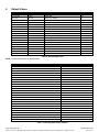
1
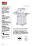
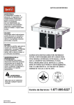
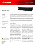
INV2000 Standalone Inverter
User Manual
014-129-B2
This page intentionally left blank.
Argus Technologies Ltd.
Burnaby, British Columbia. Telephone: 604 436 5900 Fax: 604 436 1233
Argus Technologies reserves the right to make changes to the products and information contained in this document without notice.
Copyright 2009 Argus Technologies Ltd. Argus® is a registered trademark of Argus Technologies Ltd. All Rights Reserved.
Printed in Canada.
Visit www.argus.ca
INV2000 Standalone Inverter
User Manual
014-129-B2
Applies to inverter modules 014-129-10 and 014-130-10.
The following documents and drawings are included in this manual to provide the necessary information required for
installation, operation and fault diagnosis of the unit:
• Specifications:
014-129-B1
• Installation and Operation Instructions:
014-129-C0
• Service Centers:
048-693-10
Argus Technologies Ltd.
Printed in Canada. © 2009 Argus Technologies Ltd. ARGUS is a registered trademark of Argus Technologies Ltd. All Rights Reserved.
014-129-B2 Rev A WC
Specifications for INV2000 Standalone Inverter
DC Input
Nominal Voltage:
48Vdc
Operating Range:
40 to 60Vdc within rated limits
Under Voltage Warning Threshold:
45Vdc
Under Voltage Threshold:
40Vdc
Over Voltage Warning Threshold:
58Vdc
Over Voltage Threshold:
60Vdc
Inrush current:
<2 x Irated
Isolation DC-enclosure:
707Vdc (varistors and filter capacitor removed)/1min
Input Protection:
Reverse polarity protection
Psophometric Noise Voltage:
≤1.0mV ITU-T O.41 (16.66 to 6000Hz)
Wide Band Noise:
<1.0mV (psophometric, 25Hz to 5kHz)
<20mVrms (25Hz to 20kHz)
Peak to Peak Noise:
<150mV up to 100MHz
AC Input (with transfer switch)
Voltage Range:
110/115/120Vac: 89 to 138Vac
208/220/230/240Vac: 176 to 276Vac
Over Voltage Threshold:
276 / 138Vac
Under Voltage Threshold:
176 / 89Vac
Frequency Range:
50/60 ±2.5% Hz
Back-feed Protection:
Comply with safety requirement
Transfer Time:
8ms when Inverter → Mains AC
10ms when Mains AC → Inverter
AC Output
Power Capacity:
2000VA/2000W
Waveform:
Pure sine wave
Power Factor:
1.0
Nominal Output Voltage:
110/115/120Vac or 208/220/230/240Vac
Voltage Regulation:
±2%
Output Frequency:
50/60Hz
Frequency Variation:
±0.5%
Frequency Setting:
Manually, field-selectable
Argus Technologies Ltd.
Printed in Canada. © 2009 Argus Technologies Ltd. ARGUS is a registered trademark of Argus Technologies Ltd. All Rights Reserved.
014-129-B1 Rev A WC
Page 1 of 2
Specifications for INV2000 Standalone Inverter Continued
Crest Factor:
3:1
T.H.D. (Current):
<3% for linear load, <5% for non-linear load
Capacitive/Inductive Load:
-1.0 to +1.0 without exceeding permissible distortion for resistive load
Efficiency:
>91%
Current Limitation:
Electronic current limitation at overloads and short circuits
Isolation AC-enclosure:
Basic isolation (Pri-Gnd) 2121Vdc/1min
Isolation AC-DC:
Reinforced isolation (Pri-Sec) 4242Vdc/1min
Surge Protection:
EN61000-4-5, Telcordia GR-1089 CORE, ANSI/IEEE C62.41, STD 5871980
Dynamic Response:
Better than ±10% according to IEC 62040-3 Class 1
Over Load Protection:
1.2 x Inom permanent overload capacity @30°C (86°F)
1.5 x Inom >10s
2 x Inom >5s
Mechanical
Dimensions:
43.8mm H x 440mm W x 360mm D
[1.73" H x 17.3" W x 14.2" D]
Weight:
7.4 kg (16.3 lb.) for 230Vac model
7.6 kg (16.8 lb.) for 120Vac model
Environmental
Operating Temperature:
-20 to +60°C (-4 to +140°F)
-20 to +50°C (-4 to +122°F) with full performance
Storage Temperature:
-30 to +80°C (-22 to +176°F)
Operating Humidity:
0 to 95% relative, non-condensing
Heat Dissipation:
Forced air cooling
Operating Altitude:
1500m (4922 feet)
Audible Noise:
55dB ETS 300 753 Class 3.1
Standards
Safety Compliance:
Comply with EN 60950-1/UL 60950-1
Certification:
CE
RoHS:
Compliant
EMC:
EN300 386:2001 Class B compliance
MTBF:
≥200,000 hours as per Telcordia SR-332
The above information is valid at the time of publication. Consult factory for up-to-date ordering information. Specifications are subject to change without notice.
Argus Technologies Ltd.
Printed in Canada. © 2009 Argus Technologies Ltd. ARGUS is a registered trademark of Argus Technologies Ltd. All Rights Reserved.
014-129-B1 Rev A WC
Page 2 of 2
IMPORTANT SAFETY INSTRUCTIONS
SAVE THESE INSTRUCTIONS
This section contains important instructions that should be followed during the installation and maintenance of
equipment and batteries. Please read all of the instructions before operating the equipment, and save this
manual for future reference.
The following safety symbols will be found throughout this manual, carefully read all information and abide by the
instructions:
DANGEROUS VOLTAGE
This symbol indicates a dangerous voltage
exists in this area of the product.
GAS HAZARD
This symbol indicates a gas hazard
exists in the area of vented batteries.
NO MATCHES OR OPEN FLAMES
This symbol indicates a fire or explosive hazard
exists in the area of the product.
The following levels of warning will be used with the above symbols:
DANGER:
You WILL be KILLED or SERIOUSLY INJURED if instructions are not followed closely.
WARNING:
You CAN be KILLED or SERIOUSLY INJURED if instructions are not followed closely.
CAUTION:
You CAN be INJURED or equipment can be DAMAGED if instructions are not followed closely.
Before using the product, read all instructions and cautionary markings on the product and any equipment
connected to the product.
This unit is designed for indoor use only. Do not expose the product to rain or snow; install only in a clean, dry
environment.
CAUTION – To reduce the risk of fire hazard, do not cover or obstruct the ventilation openings. Do not install the
inverter in a zero-clearance compartment.
CAUTION – Unless otherwise noted, use of an attachment not recommended or sold by the product manufacturer
may result in a risk of fire, electric shock, or injury to persons.
CAUTION – Do not operate the product if it has received a sharp blow, it has been dropped, or otherwise
damaged in any way – return it to a qualified service center for repair.
CAUTION – Do not disassemble the product – call our qualified service centers for servicing. Incorrect
reassembling may result in a risk of electrical shock or fire.
WARNING – The input and output voltages of the product are hazardous. Extreme caution should be maintained
when servicing or touching conductive components connected to the product.
Mechanical Safety
Power equipment can reach extreme temperatures under load.
Use caution around sheet metal components and sharp edges.
Electrical Safety
WARNING
To avoid a risk of fire and electric shock, make sure that existing wiring is in good condition and
that wire is not undersized. Do not operate the inverter with damaged or substandard wiring.
Before working with any live battery or power system, follow these precautions:
•
•
•
Remove all metallic jewelry; e.g., watches, rings, metal rimmed glasses, necklaces.
Wear safety glasses with side shields (and prescription lenses if necessary) at all times during installation.
Use OSHA approved insulated hand tools.
Do not work alone under hazardous conditions.
Ensure no liquids or wet clothes contact internal components.
Battery Safety
Servicing and connection of batteries shall be performed by, or under the direct supervision of, personnel
knowledgeable of batteries and the required safety precautions.
Never reverse DC+ and DC- to battery.
Keeps the battery away from heat sources including direct sunlight, open fires, microwave ovens and high-voltage
container. Temperatures over 60ºC may cause damage. Make sure the area around the battery is well ventilated.
Always wear eye protection, rubber gloves, and a protective vest when working near batteries. Remove all
metallic objects from hands and neck.
Use OSHA approved insulated hand tools. Do not rest tools on top of batteries.
Have plenty of fresh water and soap nearby in case battery acid contacts skin, clothing, or eyes.
Batteries contain or emit chemicals known to the State of California to cause cancer and birth defects or other
reproductive harm. Battery post terminals and related accessories contain lead and lead compounds; wash hands
after handling (California Proposition 65).
If battery acid contacts skin or clothing, wash immediately with soap and water. If acid enters your eye,
immediately flood it with running cold water for at least twenty minutes and get medical attention immediately.
If you need to remove a battery, always remove the grounded terminal from the battery first. Make sure all
accessories are off so you don’t cause a spark.
WARNING
Follow battery manufacturer’s safety recommendations when working around battery systems.
WARNING
Do not smoke or present an open flame when batteries (especially vented batteries) are on
charge. Batteries vent hydrogen gas when on charge, which creates an explosion hazard.
Batteries are hazardous to the environment and should be disposed of safely at a recycling facility. Consult the
battery manufacturer for recommended local authorized recyclers.
Wiring Requirements
Inverter is intended to be installed as part of a permanently grounded electrical per the National Electric Code
ANSI/NFPA 70 (current edition). This is the single point earth ground for the unit.
The ground on the Inverter is marked with this symbol: G /
The AC voltage and current on the Inverter is marked with this symbol: L / N
The DC voltage and current on the Inverter is marked with this symbol:
TABLE OF CONTENTS
SECTION
1
INTRODUCTION ............................................................................................................................................................. 1
1.1
1.2
2
Where to Install ............................................................................................................................................. 3
Unit Installation.............................................................................................................................................. 3
Unit Removal................................................................................................................................................. 3
AC Safety Grounding .................................................................................................................................... 3
DC Wiring Connections................................................................................................................................. 4
OPERATION .................................................................................................................................................................. 5
4.1
4.2
4.3
4.4
4.5
4.6
4.7
4.8
5
Packing Materials.......................................................................................................................................... 2
Check for Damage ........................................................................................................................................ 2
INSTALLATION AND WIRING........................................................................................................................................... 3
3.1
3.2
3.3
3.4
3.5
4
Scope of the Manual ..................................................................................................................................... 1
Product Overview.......................................................................................................................................... 1
INSPECTION.................................................................................................................................................................. 2
2.1
2.2
3
PAGE
Front Panel.................................................................................................................................................... 5
Rear Panel .................................................................................................................................................... 8
Pre-Operation Check .................................................................................................................................. 10
Status Monitoring ........................................................................................................................................ 10
Parameter Settings ..................................................................................................................................... 11
Alarm Settings............................................................................................................................................. 13
Remote ON/OFF Switch ............................................................................................................................. 13
Turning On The Load .................................................................................................................................. 13
MAINTENANCE AND TROUBLESHOOTING...................................................................................................................... 14
5.1
5.2
Preventative Maintenance .......................................................................................................................... 14
Troubleshooting Guide................................................................................................................................ 14
6
DEFAULT VALUES ...................................................................................................................................................... 15
7
ARGUS CONVENTIONS ................................................................................................................................................ 16
7.1
7.2
8
Numbering System...................................................................................................................................... 16
Acronyms and Definitions ........................................................................................................................... 16
OUTLINE DRAWINGS ................................................................................................................................................... 17
1
Introduction
1.1
Scope of the Manual
This instruction manual explains the features, installation, startup and maintenance of the INV2000 Standalone
Inverter.
NOTE: Images contained in this document are for illustrative purposes only and may not exactly match your installation.
1.2
Product Overview
To expand the quality power range and fulfilling the desperate demand of the total power solution for the telecom
power applications, the INVERTER 2000 provides reliable 2000W capacity in compact 1RU height, 19” width rack
design metal housing.
The higher efficiency, better over load performance, compact appearance makes INVERTER 2000 an
outstanding and perfect reliable power solutions for all types of telecom applications.
Furthermore, The INVERTER 2000 with built-in ATS function can largely increase the reliability by automatic
switch between the inverter output and other alternative AC sources which provide extra safety for uninterruptible
power. INVERTER 2000 is the indispensable power equipment for your reliable telecom system.
Features:
•
•
•
•
•
•
•
•
•
•
•
•
Designed for telecom system application
High quality pure sine wave output
Extraordinary overload capability: 120% overload continuously, 200% overload for up to 5 seconds
Remarkable efficiency: up to 91%
Unity output power factor
DSP chip design for reliable performance
Optional built-in auto transfer switch for increasing alternative reliability
LCD display for real time status monitoring and setting
USB interface for communication and connecting to PC
RoHS compliance
Low audible noise <55dBa
Wide operation temperature range, -20~60°C
Figure 1–INV2000 Standalone Inverter
Argus Technologies Ltd.
Printed in Canada. © 2009 Argus Technologies Ltd. ARGUS is a registered trademark of Argus Technologies Ltd. All Rights Reserved.
014-129-C0 Rev A WC
Page 1 of 17
2
Inspection
2.1
Packing Materials
All Argus products are shipped in rugged, double walled boxes and suspended via solid inserts to minimize shock
that may occur during transportation. Packaging assemblies and methods are tested to International Safe Transit
Association standards.
2.1.1
Returns for Service
Save the original shipping container. If the product needs to be returned for service, it should be packaged in its
original shipping container. If the original container is unavailable, make sure the product is packed with at least
three inches of shock-absorbing material to prevent shipping damage.
NOTE: Argus Technologies is not responsible for damage caused by the improper packaging of returned products.
2.2
Check for Damage
Prior to unpacking the equipment, perform a visual inspection and note any damage. Unpack the equipment and
inspect the exterior for damage. If any damage is observed contact the carrier immediately.
In addition to the inverter module (Figure 1), the mounting kit provided consists of:
4 x M4 screws to connect the brackets to the cabinet:
23” mounting brackets:
Parallel signal port cover:
Continue the inspection for any internal damage. In the unlikely event of internal damage, please inform the
carrier and contact Argus Technologies for advice on the consequence of any damage.
Verify that you have all the necessary parts per your order for proper assembly.
Call Argus Technologies if you have any questions before you proceed: 1 (888) 462-7487
Customers outside Canada and the USA, call +1-604-436-5547 for technical support.
Argus Technologies Ltd.
Printed in Canada. © 2009 Argus Technologies Ltd. ARGUS is a registered trademark of Argus Technologies Ltd. All Rights Reserved.
014-129-C0 Rev A WC
Page 2 of 17
3
Installation and Wiring
3.1
Where to Install
The power inverter should be installed in a location that meets the following requirements:
•
Dry: Do not allow water to drip or splash on the inverter.
•
Cool: Ambient air temperature should be between -20°C and 60°C.
•
Safe: Do not install in a battery compartment or other areas where flammable fumes may exist, such as fuel
storage areas or engine compartments.
•
Ventilated: Allow at least three inches of clearance around the inverter for airflow, ensuring that the
ventilation openings on the front, rear and top of the unit are not obstructed.
•
Dust Free: Do not install the inverter in a dusty environment where dust, wood particles or other
filings/shavings are present that may be pulled into the unit when the cooling fan is operating.
•
Close to Batteries: Avoid excessive cable lengths but do not install the inverter in the same compartment as
batteries. Use the recommended wire lengths and sizes (see section 3.5).
Avoid mounting the inverter where it may be exposed to the gases produced by the battery. Prolonged exposure
to these corrosive gases will damage the inverter.
3.2
Unit Installation
The unit is pre-installed with 19-inch rack brackets. Put the unit to the rack horizontally, and align holes of
mounting brackets and rack. Secure the unit in position with four cross-pan type nickel screws.
3.3
Unit Removal
The unit can be removed from the equipment rack by screwing off the retaining screws.
3.4
AC Safety Grounding
During the AC wiring installation, AC input and output ground wires are connected to the inverter. The AC input
ground wire must connect to the incoming ground from your AC utility source.
The AC output ground wire should go to the grounding point for your loads.
WARNING
Do not operate the unit without connecting it to ground. Electrical shock hazard may result.
Argus Technologies Ltd.
Printed in Canada. © 2009 Argus Technologies Ltd. ARGUS is a registered trademark of Argus Technologies Ltd. All Rights Reserved.
014-129-C0 Rev A WC
Page 3 of 17
3.5
DC Wiring Connections
Connect the cables to the power input terminals on the rear panel of the unit.
【+】is positive, and【-】is negative. Insert the cables into the terminals and tighten the nut to securely clamp
the wires.
DC +
DC -
Figure 2–DC input terminals
WARNING
Before proceeding, confirm that DC input cable connect correctly.
Make sure that all DC connections are tight (torque to 9-10 foot pounds). Loose connections will
overheat and could result in a potential hazard.
Follow this procedure to connect the battery cables to the DC input terminals on the unit.
The cables should be as short as possible (ideally, less than 10 feet / 3 meters) and large enough to handle the
required current in accordance with the electrical codes or regulations applicable to your installation. Cables that
are not an adequate gauge (too narrow) or are too long will cause decreased inverter performance such as poor
surge capability and frequent low input voltage warnings and shutdowns. These low input voltage warnings are
due to DC voltage drip across the cables from the inverter to the batteries. The longer and narrower these cables,
the greater the voltage drop.
CAUTION – Increasing your DC cable size will help improve the situation.
NOTE: We recommend #6 AWG 40A cables (48Vdc input) for optimum inverter performance (applies to both 110V and
220V series). Use only high quality copper wiring and keep cable length short (from 3-6 feet).
Argus Technologies Ltd.
Printed in Canada. © 2009 Argus Technologies Ltd. ARGUS is a registered trademark of Argus Technologies Ltd. All Rights Reserved.
014-129-C0 Rev A WC
Page 4 of 17
4
Operation
4.1
Front Panel
Located on the front panel is the interface for signals and controls:
•
Control: Keypad to set major parameters
•
Remote Control/Monitoring: USB
•
Display: LCD and 3-LEDs to display major parameters, status and alarms
LCD
Handle
LED indicators
ON/OFF switch
Function keys
USB port
Figure 3–Front panel
4.1.1
ON/OFF Switch
The POWER ON/OFF switch is a lock switch that turns the unit on or off by pressing it once.
4.1.1.1
Switch on:
When the unit is connected to the DC, LCD will show content, press ON/OFF switch, unit will
provide power to load in 20s.
When the unit is only connected to the AC, LCD will show content, press ON/OFF switch, unit
will provide power to load in 5s.
4.1.1.2
Switch off:
When unit is working, press ON/OFF switch will turn unit off, if DC or AC power exists, LCD will
show content continually.
Unit shuts off when input power out of range, and it can auto restart if on/off switch is at on position and input DC
or AC power recover.
4.1.2
USB Port
User can operate Hyper terminal by connect the USB Cable to the USB interface on the front panel. The USB is
1.1.
Hyper Terminal
USB Cable
Figure 4–USB connectivity
Argus Technologies Ltd.
Printed in Canada. © 2009 Argus Technologies Ltd. ARGUS is a registered trademark of Argus Technologies Ltd. All Rights Reserved.
014-129-C0 Rev A WC
Page 5 of 17
4.1.3
LED Indicators
Inverter Module LED Display Status
Green LED
Priority
Priority
Priority
LED Signal
Status
Solid
Inverter work normally
Blink (intermittent (slow))
One of the status as follows:
1) Power On.
Details refer to note.
2) Shut down remotely.
Yellow LED
LED Signal
Status
Blink (intermittent (slow))
Power On
Details refer to note.
Solid
One of the alarms as follows:
1) Over Load (Load > 105%);
2) DC input abnormal.
(Vin<=45V or Vin>=58V)
Blink (intermittent (fast))
Inverter shut down due to DC super
low/super high input.
(Vin<=VLVSD or Vin>=VHVSD)
Red LED
LED Signal
Status
Blink (slow)
One of the alarms as follows:
1) EEPROM Fault;
2) Inverter Fan Fault.
Blink (fast)
One of the alarms as follows:
1) Internal fault;
2) Temperature High.
Solid
One of the alarms as follows:
1) Input reverse polarity;
2) Inverter output Short circuit;
3) Abnormal output voltage;
4) Negative Power Protection;
5) Overload fault.
Table A–Inverter LED indicator display
4.1.3.1
Power On:
When the inverter is in “Power On” mode, the green LED and the yellow LED are flickering
synchronously without any alarm.
4.1.3.2
Overload and Overload Fault:
When overload fault alarm occurs, the yellow LED and red LED turn on at the same time, while
overload alarm occurs, only the yellow LED turns on.
4.1.3.3
Priority:
If more than one warning exists at the same time, then the LED will display the highest priority.
Argus Technologies Ltd.
Printed in Canada. © 2009 Argus Technologies Ltd. ARGUS is a registered trademark of Argus Technologies Ltd. All Rights Reserved.
014-129-C0 Rev A WC
Page 6 of 17
4.1.4
LCD Menu Structure
10
18
Alarm Num: 1
1.Fan Lock
ALARM
19
5
6
7
4
Status
► Inverter
Alarm
Ver&No
8
1
Waiting
……
1. OPV xxx.xV ▲
2. OPI
x.xxA
3. OPF xx .xxHz
4. OPP xxxVA▼
16
INVER
TER
5. Input Volt
▲
xx.xxV
6. PowerUsed
xx% ▼
Inv OutputVolt
Inv OutputFreq
Inv HighLoss
Inv LowLoss
IPV LVSD
IPV HVSD
Power Limited
Inv OnOff
MainsAC HL
MainsAC LL
Priority
7. Ambient Temp ▲
xx.x℃
8. PowerLimited
xxx%
▼
9
2
11. Priority :
BAT. MODE ▲
21
OPV LL
xxxV
22
IPV LVSD
xx.xV
23
IPV HVSD
xx.xV
Power Limited
xxx%
⊙ ON
○ OFF
26
1.INV: xxx.xV
2.ACV: xxx.xV
3.OPV: xxx.xV
4.Priority: xxxx
AC HL:
xxxV
27
11
ENTER
3
Main Menu
► Status
Settings
1. HW Ver
x.xx
2. SW Ver
x.xx
AC LL:
xxxV
▲
▼
⊙ 110V
○ 115V
○ 120V
or
OutputFreq:
⊙ 50Hz
○ 60Hz
OPV HL
xxxV
25
INV
STATUS
208V
220V
230V
240V
20
24
9. Mains AC Volt ▲
xxx.xV
10. Mains AC Freq
xx.xHz ▼
○
○
⊙
○
28
Priority :
⊙ BAT. MODE
○ LINE MODE
Ver&No
12
3.Serial No:
**** *****
31
15
Enter
password :
SETTING
****
13
OK
Module settings
► Inverter
System
32
17
System
34
14
WRONG
► 1.Language
2.Password
3.Brightness
4.Default Setting
Access Denied!
35
Language:
⊙ English
○ Simp .Chinese
○ Trad.Chinese
Setting
Password:
****
Brightness:
xx↕
33
36
Setting again
Password:
****
Setting Wrong
Password
Restore factory
setting
37
Display fail!
When the communication
between LCD and DSP failed
38
When the setting operation from
LCD failed
Set fail!
Argus Technologies Ltd.
Printed in Canada. © 2009 Argus Technologies Ltd. ARGUS is a registered trademark of Argus Technologies Ltd. All Rights Reserved.
014-129-C0 Rev A WC
Page 7 of 17
4.2
Rear Panel
Located on the rear panel are the terminations for wiring:
AC input breaker
AC input terminal
Parallel signal port
reserved and not
available
DC input terminal
Alarm output port
AC output terminal
Remote ON/OFF switch
Figure 5–Rear panel
4.2.1
DC Input
ST722B2502 (300 Volts (UL 1059 Class B and C) / 175 Amps)
Wire Range #2 - #8
(Accommodates two-hole compression lugs on 0.625" centers – wires #2 and larger may require narrow lugs)
DC +
DC -
Figure 6–DC input terminals
Connect to a 48Vdc battery or DC power source.
Upper terminal【+】is positive, and【-】is negative. Reverse polarity connection will cause red alarm LED to
illuminate (indicator solid), but inverter will not be damaged.
4.2.2
AC Input
230Vac model: RECEPTACLE /WS-044-7 16A 250V INLET GAP1.5
120Vac model: cable P.C.#12*3C 20A 125Vac 5-20P UL 2200
4.2.3
AC Input Breaker
230Vac model: N.F.B1P15A 250Vac JOEMEX/PE747415-214D-051
120Vac model: NFB 1P20A/120Vac (CIRCUIT PROTECTOR) UL489
4.2.4
AC Output
230Vac model: AC output outlet IEC320-C13 10A 250Vac
120Vac model: REC. RON/RF-6005-A 5-20R 20A 125V 3P
Argus Technologies Ltd.
Printed in Canada. © 2009 Argus Technologies Ltd. ARGUS is a registered trademark of Argus Technologies Ltd. All Rights Reserved.
014-129-C0 Rev A WC
Page 8 of 17
4.2.5
Alarm Relay
Figure 7–Rear panel alarm output port
4.2.6
Remote ON/OFF Switch
Inverter will be turned on/ off after remote Switch 0.5s.
PIN1, PIN2 open, unit will be remote off; closed, unit will work.
Remote SW Output Status
Open
Close
Off
On
Figure 8–Rear panel remote ON/OFF switch
Once the module is ON use this switch to stop unit remotely.
Restart method: close the remote switch - unit will auto restart.
Remote switch is available when power ON/OFF switch is at “ON” position.
Argus Technologies Ltd.
Printed in Canada. © 2009 Argus Technologies Ltd. ARGUS is a registered trademark of Argus Technologies Ltd. All Rights Reserved.
014-129-C0 Rev A WC
Page 9 of 17
4.3
Pre-Operation Check
Inverter Operation Check
•
•
•
•
•
•
Check if the DC input polarity is connected correspondingly.
Ensure the input voltage is in the standard range.
Check corrected connecting wiring size based on the wiring table.
Check if the ground wiring is connected on rear cover for safety, avoiding electrical shock.
The breakers are at ON position.
To operate the Auto Transfer Switch it is necessary to make sure that the nominal voltage and frequency of
the grid match the corresponding settings of the unit.
Verify that the nominal frequency and voltage values are equal to those of the grid.
4.4
Status Monitoring
When the inverter is properly installed with power on, the LCD screen would light by displaying “Waiting” for selfdiagnosis. Few seconds after, general status is shown as follows.
Waiting ...
1.INV:
xxx.xV
2.ACV:
xxx.xV
3.OPV:
xxx.xV
4.Priority: BAT.
Figure 9–Power start page
Press “Enter
” key, “Main Menu” will be shown as follow, “STATUS” and “SETTINGS” menu can be selected
via pressing “PgDn ”or “PgUp ” and “Enter
” key.
Figure 10–Main menu
Heading
Address
OPV
OPI
OPF
OPP
Input Volt
Power Used
Ambient Temp.
Power Limited
Mains AC Volt
Mains AC Freq
Priority
Value
Inverter module location
Output voltage of the inverter module in Volts (V)
Output current of the inverter module in Amperes (A)
Output frequency of the inverter module in Hertz (Hz)
Power capacity of the inverter module in Volt-Amperes (VA)
DC input voltage of the inverter in Volts (V)
Load level in percentage (%)
Inverter ambient temperature (ºC)
Power limited in percentage (%)
Voltage of Mains AC
Frequency of Mains AC
On-line/Off-line
Table B–LCD display of inverter status
Argus Technologies Ltd.
Printed in Canada. © 2009 Argus Technologies Ltd. ARGUS is a registered trademark of Argus Technologies Ltd. All Rights Reserved.
014-129-C0 Rev A WC
Page 10 of 17
Item
Inverter
Specification
Alarm name
Remark
For example:
Alarm Num: 1
1. Fan Lock
Table C–LCD display of alarm log
Heading
HW Ver
SW Ver
Serial No.
Value
Hardware version of the inverter module
Software version of the inverter module
The serial number of the inverter
Table D–LCD display of version and SN
4.5
Parameter Settings
Inverter allows some parameters reset through the key function and LCD. Use PgDn key and Enter
key to
select SETTINGS. 4-digit numeric password is requested. Use PgUp key to increase number, and PgDn key
to decrease number. For instance, press PgUp key once for 1, twice for 2, three times for 3, and so on. Press
Enter
to validate each digit of password once the desired number is selected. The default password is 0000.
No setting modification can be executed if a wrong password is entered.
0***
Figure 11–Password input
Password Setting
1. A new password can be set in SYSTEM option under SETTINGS. Press Enter
key to enter SETTING
PASSWORD menu for resetting password.
to validate each digit of password
2. Use PgUp key and PgDn key to key in new password. Press Enter
once the desired number is selected.
3. After 4-digit new password is input, the inverter would ask to re-key in the new password as confirmation.
Repeat Step 2 to key in the new password again. Once the password is successfully changed, DONE will
appear on the screen.
Argus Technologies Ltd.
Printed in Canada. © 2009 Argus Technologies Ltd. ARGUS is a registered trademark of Argus Technologies Ltd. All Rights Reserved.
014-129-C0 Rev A WC
Page 11 of 17
SETTINGS section is divided into two categories: SYSTEM and INVERTER.
4.5.1
System Parameter Settings
Parameter
Language
Password
Brightness: LCD Brightness
Restore Factory Setting
Specification
English
Setting password
From 00~63 for adjusting LCD display contrast
Reset default value
Table E–System parameter settings
4.5.2
Inverter Parameter Settings
Parameter
Output volt:
Inverter output voltage
Output Freq:
Inverter output frequency
OPV HL:
High loss of inverter output voltage
OPV LL:
Low loss of inverter output voltage
IPV LVSD: The maximal input voltage for
inverter normal operation
IPV HVSD: The minimal input voltage for
inverter normal operation
Power Limited:
Inverter output power capacity
Inverter On/off:
Setting inverter turn on or off
AC HL: High loss of alternative AC input
AC LL: Low loss of alternative AC input
Priority
Setting Option
For 230Vac output, selectable at:
1) 208Vac 2) 220Vac 3) 230Vac
For 110Vac output, selectable at:
1) 110Vac 2) 115Vac 3) 120Vac
Selectable at 1) 50Hz and 2) 60Hz
4) 240Vac
For Output volt = 208V, adjustable between 220V and 240V
For Output volt = 220V, adjustable between 233V and 252V
For Output volt = 230V, adjustable between 244V and 264V
For Output volt = 240V, adjustable between 254V and 276V
For Output volt = 110V, adjustable between 117V and 127V
For Output volt = 115V, adjustable between 122V and 132V
For Output volt = 120V, adjustable between 127V and 138V
For Output volt = 208V, adjustable between 176V and 198V
For Output volt = 220V, adjustable between 176V and 209V
For Output volt = 230V, adjustable between 185V and 218V
For Output volt = 240V, adjustable between 193V and 228V
For Output volt = 110V, adjustable between 89V and 105V
For Output volt = 115V, adjustable between 93V and 110V
For Output volt = 120V, adjustable between 100V and 114V
Adjustable between 39V and 44V
Adjustable between 59V and 61V
Adjustable between 50% and 100%
⊙ ON
○ OFF
xxxV
xxxV
Bat. Mode / Line Mode
Table F–Inverter parameter settings
Argus Technologies Ltd.
Printed in Canada. © 2009 Argus Technologies Ltd. ARGUS is a registered trademark of Argus Technologies Ltd. All Rights Reserved.
014-129-C0 Rev A WC
Page 12 of 17
4.6
Alarm Settings
Use #30~16 AWG to connect dry contact:
Figure 12–Rear panel alarm output port
4.7
Remote ON/OFF Switch
Use #30~16 AWG to connect remote ON/OFF switch:
Remote SW Output Status
Open
Close
Off
On
Figure 13–Rear panel remote ON/OFF switch
4.8
Turning On The Load
Check that the rated input power of the load is less or equal to the rated output power of the inverter.
Connect the load to the inverter as described previously.
Press the ON/OFF key to turn the unit ON.
Argus Technologies Ltd.
Printed in Canada. © 2009 Argus Technologies Ltd. ARGUS is a registered trademark of Argus Technologies Ltd. All Rights Reserved.
014-129-C0 Rev A WC
Page 13 of 17
5
Maintenance and Troubleshooting
5.1
Preventative Maintenance
The following preventive maintenance routines should be considered as a minimum requirement. Your installation
may require additional preventive maintenance to assure optimal performance from your installed inverter and
associated equipment. These routines should be performed twice a year (more often if required). We strongly
recommend a contract with Customer Support Services for preventive and remedial maintenance. The technician
or electrician performing preventive maintenance on the equipment must read and understand thoroughly this
manual and be familiar with the indicators, controls, and operation of the equipment.
5.2
Troubleshooting Guide
If the inverter fails to operate properly after having the installation and setup of the inverter thoroughly reexamined, use the troubleshooting table to determine the probable cause(s) and solution(s) to resolve error
conditions. For unlisted error conditions, please contact your local dealer for technical assistance.
Error Condition
No AC output
and all LEDs off.
No AC output.
Both green and yellow
LEDs flicker.
No AC output.
Both yellow and red
LEDs are on.
Possible Cause
Recommendation
Lack of input power.
Ensure input cables are all firmly connected to
power source.
Check if power source is not yet switched on, or
is low in power.
Inverter self-diagnosis.
Inverter self-diagnosis takes a few seconds.
LED turns to a solid green light after the
completion of self-diagnosis.
Load exceeds 125%.
Ensure the load is no higher than 105% of the
total power rating. Reduce as required.
1. Input wiring is connected in reverse (i.e.
reverse polarity).
No AC output.
Red LED is on.
2. Internal fault.
3. Inverter output is shorted.
4. Negative Power Protection.
1. Inverter fails to soft start.
Red LED blinks fast.
AC output exists with
yellow LED flickering.
AC output exists and
yellow LED is on.
Ensure input cables are connected to correct
polarity (positive to positive, negative to
negative).
Restart the unit. If it fails to work, return it to
factory for repair.
Turn off the input power source to remove all
short circuits.
When transfer between Mains and inverter, mains
backfeed to inverter.
Reboot the inverter system by switching off and
on the input power source.
2. Inverter temperature rises beyond the
temperature limit.
Leave inverter idle to cool down for few minutes.
Input voltage is out of operating range.
Ensure input voltage is between 45 to 58Vdc.
Load is over 100% but below 125%.
Inverter continuously
Failure of EEPROM.
delivers power, but with
red LED flickering
Fans failure.
slowly.
Ensure the load is no higher than 105% of the
total power rating. Reduce as required.
Reboot the inverter system by switching off and
on the input power source.
Check if the fans are locked or fail to work.
If fan is locked, remove the obstruction;
if fan fails to work, replace the fan.
Table G–Troubleshooting for inverter module
Argus Technologies Ltd.
Printed in Canada. © 2009 Argus Technologies Ltd. ARGUS is a registered trademark of Argus Technologies Ltd. All Rights Reserved.
014-129-C0 Rev A WC
Page 14 of 17
6
Default Values
Alarm Name
Inverter fault
Over load
Over load fail
Inv fan fault
Power limit
DC abnormal
DC low Inv off
Inv Bus High
Inv Bus Low
BusSoft fail
Output short
Inv OPV Low
Inv OPV High
Inv Temp High
NegPow Protect
SoftStart fail
Mains abnormal
Eeprom fail
Level
Critical
Observe
Critical
Major
Observe
Observe
Observe
Critical
Critical
Critical
Critical
Critical
Critical
Critical
Critical
Critical
Observe
Major
Remark
Inverter fault
Inverter over-loading
Over load shut down
Inverter fan fault
Inverter power limited
Inverter input out of range
Inverter shut down due to low input voltage
Inverter Bus voltage over the maximum level
Inverter Bus voltage under the minimum level
Inverter Bus soft start fail
Inverter output short circuit
Inverter output voltage low
Inverter output voltage high
Inverter temperature high
Inverter negative power protection
Inverter soft start fail
Mains unavailable
Inverter EEPROM fault
Output Status
Off
On
Off
On
On
On
Off
Off
Off
Off
Off
Off
Off
Off
Off
Off
On
On
Table H–Alarm default levels
NOTE: Critical level fault needs manual restart.
Setting
ATS priority
230Vac Unit
Mains high loss volt
Mains low loss volt
Inverter output high loss volt
Inverter output low loss volt
Inverter shutdown due to low input volt
Inverter shutdown due to high input volt
Inverter output volt
Inverter output volt frequency
Inverter output power limit
120Vac Unit
Mains high loss volt
Mains low loss volt
Inverter output high loss volt
Inverter output low loss volt
Inverter shutdown due to low input volt
Inverter shutdown due to high input volt
Inverter output volt
Inverter output volt frequency
Inverter output power limit
System Parameter
LCD brightness value
Language
Password
Default Value
On-line
276V
176V
264V
192V
40V
60V
230V
50Hz
100%
138V
89V
140V
90V
40V
60V
120V
60Hz
100%
45
English
0000
Table I–Inverter/System factory defaults
Argus Technologies Ltd.
Printed in Canada. © 2009 Argus Technologies Ltd. ARGUS is a registered trademark of Argus Technologies Ltd. All Rights Reserved.
014-129-C0 Rev A WC
Page 15 of 17
7
Argus Conventions
7.1
Numbering System
Argus Technologies uses an eight-digit drawing number system, which is broken into three blocks. The first three
digits describe the category of the product; e.g., rectifier or fuse panel. The next three digits indicate the sequence
in which the product number was allocated in a particular category. The last two digits indicate the type of
drawing, for example:
“-06”
“-08”
“-20”
Outline Drawing
Customer Connections
Main Assembly
Argus uses an eight-digit part numbering system for all components and sub assemblies. Each part is covered by
its own unique number. Due to the quantity, categories will not be listed within this manual.
7.2
Acronyms and Definitions
AC
ANSI
ATS
AWG
COM
CSA
DC
DSP
EMC
HVSD
IEC
LCD
LED
LVSD
MTBF
NC
NO
OSHA
PC
RoHS
RU
THD
UL
USB
Alternating current
American National Standards Institute
Automatic Transfer Switch
American Wire Gauge
Common
Canadian Standards Association
Direct current
Digital signal processor
Electromagnetic compatibility
High voltage shutdown
International Electrotechnical Commission
Liquid crystal display
Light emitting diode
Low voltage shutdown
Mean time between failures
Normally closed
Normally open
Occupational Safety & Health Administration
Personal computer
Restriction of hazardous substances
Rack unit (1.75”)
Total harmonic distortion
Underwriters Laboratories
Universal serial bus
U
U
U
U
U
U
U
U
U
U
U
U
U
U
U
U
Argus Technologies Ltd.
Printed in Canada. © 2009 Argus Technologies Ltd. ARGUS is a registered trademark of Argus Technologies Ltd. All Rights Reserved.
014-129-C0 Rev A WC
Page 16 of 17
8
Outline Drawings
Figure 14–Rear panel views
Figure 15–Dimensional views
Argus Technologies Ltd.
Printed in Canada. © 2009 Argus Technologies Ltd. ARGUS is a registered trademark of Argus Technologies Ltd. All Rights Reserved.
014-129-C0 Rev A WC
Page 17 of 17
Service Centers
Factory Service Centers
Canada and International
Argus Technologies Ltd.
ATTN: RMA Returns
7033 Antrim Avenue
Burnaby, BC, V5J 4M5 Canada
Tel: +1 604 436 5900
Fax: +1 604 436 1233
Email: [email protected]
USA
Argus Technologies Inc.
ATTN: RMA Returns
3116 Mercer Avenue
Bellingham, WA, 98225 USA
Tel: +1-360 756 4904
Fax: +1-360 647 0498
Email: [email protected]
Asia-Pacific
PCM Electronics (Dong Guan) Co., Ltd.
Hongli Industrial Area, Miaobian,
Liaobu Town, Dongguan City,
Guangdong Province, 523400 China
Tel: +86 755 8895 3310
Fax: +86 755 8895 3307
Brazil
Argus Brasil Serviços e Comércio Ltda
Rua: Constituição,145/147 - Santos
São Paulo – Brasil 11015-471
Tel: +55 (13) 3234 2469
Fax: +55 (13) 3234 2469
Cell: +55 (13) 7806 1438
Email: [email protected]
South America
Argus Technologies Argentina
Santo Tome 2573, Capital Federal
Buenos Aires, 1416 Argentina
Tel: +54 11 4504 4698
Cell: +54 9 11 4993 9996
E-pager: [email protected]
Authorized Service Center
Argentina
Argus Technologies de Argentina
Belen 315, Capital Federal, Buenos
Aires,
1407l Argentina
Tel: +54 (11) 4672 4821
Fax: +54 (11) 4504 4698
Cell: +54 9 (11) 4993 9996
Email: [email protected]
Asia
Argus Technologies Asia Pte Ltd
Blk 6 Tagore Lane #160
Singapore 787570
Tel: +65 6458 8900
Fax: +65 6458 2122
Australia
CPS National
8/376 Newbridge Rd
Moorebank, NSW, 2170 Australia
Tel: +61 02 9822 8977
Fax: +61 02 9822 8077
Australia/New Zealand
Alpha Power Systems Pty Ltd.
Unit 3, 30 Heathcote Road
Moorebank, NSW, 2170 Australia
Tel: +61 02 9602 8331
Fax: +61 02 9602 9180
Century Yuasa
37 - 65 Colbalt Street
Carole Park QLD 4300
Australian Sales & Service
Tel: +61 07 3361 6587
Fax: +61 07 3361 6705
New Zealand Sales & Service
Tel: +64 9 978 6689
Fax: +64 9 978 6677
Canada
Compower Systems Inc.
118 Tiffield Road
Toronto, ON, M1V 5N2 Canada
Tel: +1 416 293 3088
Fax: +1 416 293 0671
Turkey
IPC Enerji Elk San ve TIC AS
Inonu cad. Kanarya sok. No:20
Yenisahra - Kadikoy
Istanbul, Turkey
Tel: +90 216 317 41 42
Fax: +90 216 472 90 66
Europe
Alpha Technologies Europe Ltd.
Cartel Business Estate
Edinburgh Way
Harlow, Essex, CM20 2DU UK
Tel: +44 1279 422110
Fax: +44 1279 423355
Mexico & Central America
Technologies Argus First De Mexico
SA de CV
Anatole France No. 17
Col. Polanco
Mexico City, 11560 Mexico
Tel: +52 55 5280 6990
Fax: +52 55 5280 6585
Romania
Alphapower SRL
Str. Paul Constantinescu nr.5
Timisoara, Romania
Tel: +40 21 569 1214
Cell: +40 31 816 1491
048-693-10 Rev C (04/2008)
Canada and USA toll free 24 hour emergency technical support: +1 888 GO ARGUS (462 7487) Outside North America: +1 604 436 5547