1
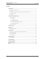
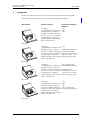
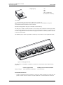
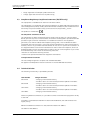
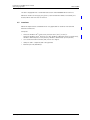
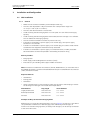
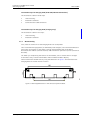
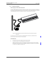
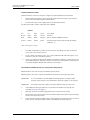
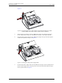
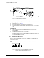
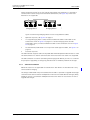
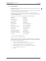
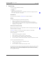
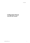
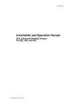
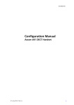
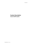
TD 92480EN
Installation and Operation
Manual
CR3, Charging Rack
25 May 2011/ Ver. E
Installation and Operation Manual
CR3 Charging Rack
TD 92480EN
Contents
1 Introduction....................................................................................................................... 1
1.1 Abbreviations and Glossary ...................................................................................................... 3
1.2 Safety ............................................................................................................................................. 3
1.3 Compliance Regulatory Compliance Statements (EU/EFTA only) ................................... 4
1.4 Technical Solution ....................................................................................................................... 4
1.5 Interfaces ....................................................................................................................................... 5
2 Installation and Configuration ........................................................................................ 6
2.1 CR3 Installation ............................................................................................................................ 6
2.1.1 General ................................................................................................................................. 6
2.1.2 Wall mounting ................................................................................................................... 7
2.1.3 Electrical installation ........................................................................................................ 8
2.1.4 Communication cable connection ...............................................................................12
2.1.5 Software installation ......................................................................................................13
2.2 CR3 Configuration .....................................................................................................................14
3 Commissioning ................................................................................................................ 14
4 Operation ......................................................................................................................... 16
4.1 Charger Operation .....................................................................................................................16
5 Maintenance .................................................................................................................... 17
5.1 Operation when charger is connected to PDM/IMS3 .......................................................17
5.2 Software Update .......................................................................................................................17
5.3 Easy Replacement .....................................................................................................................17
5.4 LED indications ...........................................................................................................................18
6 Administration ................................................................................................................ 18
6.1 Data backup ................................................................................................................................18
7 Troubleshooting .............................................................................................................. 19
8 Related Documents ......................................................................................................... 20
9 Document History ........................................................................................................... 20
Index .................................................................................................................................. 21
25 May 2011/ Ver. E
Installation and Operation Manual
CR3 Charging Rack
1
TD 92480EN
Introduction
This document describes how to install, configure and operate the CR3 Charging Rack.
There are five different revisions/variants of CR3 Charging Rack available:
Item Number
Charger functions
Used for the following
handsets:
- Charging
- i621
- Equipped with a USB port and - d62
two Ethernet ports, making it - d41
possible to connect it directly to
a LAN or to a PC for the purpose
of upgrading or configuring
handsets placed in the Charging
Rack or the CR3 itself.
CR3-AAAA
- Charging
- Equipped with a USB port and
two Ethernet ports, making it
possible to connect it directly to
a LAN or to a PC for the purpose
of upgrading or configuring
handsets placed in the Charging
Rack or the CR3 itself.
- d81
IMPORTANT: Do NOT use
for EX classified d81
handsets if the Charging
Rack’s revision is “1A”.
See the charger’s label.
CR3-AAAB
- Charging
- Equipped with a USB port and
two Ethernet ports, making it
possible to connect it directly to
a LAN or to a PC for the purpose
of upgrading or configuring
handsets placed in the Charging
Rack or the CR3 itself.
- d81 (including EX
classified d81 handsets).
IMPORTANT: The
Charging Rack’s revision
must be “2A” or higher.
See the charger’s label.
CR3-AAAB
- Charging
- Equipped with a USB port and
two Ethernet ports, making it
possible to connect it directly to
a LAN or to a PC for the purpose
of upgrading or configuring
handsets placed in the Charging
Rack or the CR3 itself.
- i621
- d62
- d41
- d81 (including EX
classified d81 handsets).
CR3-AAAC
25 May 2011/ Ver. E
1
Installation and Operation Manual
CR3 Charging Rack
TD 92480EN
- Charging only
- i62
- d62
- d41
- d81 (including EX
classified d81 handsets).
CR3-ABAC
1.For i62 handsets, this version/revision of CR3 works as a charger only.
Note: The CR3 Charging Racks with Ethernet connections are intended to always be
connected to Ethernet based local area network.
Each CR3 Charging Rack charges six handsets simultaneously.
The USB port is used to connect the CR3 to a PC running the Portable Device Manager (PDM)
or to the Integrated Wireless Messaging and Services application (IMS3). This program can
be used to upgrade the software and to configure parameters in handsets placed in the CR3
as well as the CR3 itself.
The Ethernet ports makes it possible to connect up to four CR3’s to one single LAN outlet.
Figure 1.
Figure 1. Charging Rack CR3.
This document is intended as a guide for installation, maintenance and troubleshooting
purposes.
Supply voltage
Power Supply for CR3
Building fuse for fixed installation
100-240VAC/0.7A 50/60 Hz
10 A maximum
Installation alternatives
•
The CR3 as delivered can be installed as a single unit. When installed as a single unit, the
power cord with the C14 connector may be used with a suitable extension cord to be
25 May 2011/ Ver. E
2
Installation and Operation Manual
CR3 Charging Rack
TD 92480EN
plugged into a wall outlet. Up to four single units may be connected to one single LAN
outlet.
• If more than one CR3 is used in a serial configuration a fixed installation must be made.
For safety reasons it is NOT allowed to supply more than one unit by the power cord with
the C14 connector. When units are supplied in series, the installation must be made by
an authorized electrician and the C14 connectors must be removed. Maximum five units
may be connected in serial power supply, but LAN serial connection is limited to four
units.
In Sweden, Norway and Finland a connection to protective earth (safety grounding) must be
provided.
In the USA and Canada the CR3 must only be installed as a single unit, serial configuration is
not permitted.
1.1
1.2
Abbreviations and Glossary
BPC
Battery Pack Charger
device
Can be a DECT or VoWiFi handset, an alarm transmitter, a
pager or a charger developed to work together with the PDM/
IMS3. See respective manual for each device.
DHCP
Dynamic Host Configuration Protocol, a protocol for
automating the configuration of computers that use TCP/IP
IMS3
Integrated Wireless Messaging and Services
An application running on an ELISE3 module, that enables
wireless services to and from portable devices and chargers.
PDM
Portable Device Manager
A Stand Alone (SA) for administration via a cable connected
PC.
USB
Universal Serial Bus: a serial bus standard to interface
devices, for example connect computer peripherals such as
mice, keyboards, scanners etc.
Safety
The Charging Rack CR3 is connected to 100-240VAC/0.7A 50/60 Hz. For safety reasons:
•
•
the safety covers on top of the supply voltage terminal blocks must be mounted to
prevent hazardous situations, like electric shock.
when servicing the units the mains power supply cable must be disconnected.
Note the following:
-
-
for PERMANENTLY CONNECTED EQUIPMENT, a readily accessible disconnect device
shall be incorporated in the building installation wiring. The disconnect device shall
disconnect both poles.
for PLUGGABLE EQUIPMENT, the socket-outlet shall be installed near the equipment
and shall be easily accessible.
In Sweden, Norway and Finland the unit must be connected to a wall outlet with protective
earth (safety grounding). For other countries it is recommended to use a protective earth
connection.
•
Suomi: Laite on liitettävä suojamaadoituskoskettimilla varustettuun pistorasiaan.
25 May 2011/ Ver. E
3
Installation and Operation Manual
CR3 Charging Rack
•
•
1.3
TD 92480EN
Norge: Apparatet må tillkoples jordet stikkontakt.
Sverige: Apparaten skall anslutas till jordat uttag.
Compliance Regulatory Compliance Statements (EU/EFTA only)
This equipment is intended to be used in the whole EU & EFTA.
This equipment is in compliance with the Council Directive on Radio and Telecommunication
Terminal Equipment (R&TTE) 1999/5/EC and ErP Directive 2009/125/EC. The Declaration of
Conformity may be consulted at: http://www.ascom.com/ws/products_ws.htm
The product is marked with
.
FCC compliance statements for USA
This equipment has been tested and found to comply with the limits for a Class B digital
device, pursuant to part 15 of the FCC Rules. These limits are designed to provide reasonable
protection against harmful interference in a residential installation. This equipment
generates, uses and can radiate radio frequency energy and, if not installed and used in
accordance with the instructions, may cause harmful interference to radio communications.
However, there is no guarantee that interference will not occur in a particular installation. If
this equipment does cause harmful interference to radio or television reception, which can
be determined by turning the equipment off and on, the user is encouraged to try to correct
the interference by one or more of the following measures:
• Reorient or relocate the receiving antenna.
• Increase the separation between the equipment and receiver.
IC Requirements for Canada
This Class B digital apparatus complies with Canadian ICES-003.
Cet appareil numérique de la Classe B conforme á la norme NMB-003 du Canada.
1.4
Technical Solution
The following functionality is provided by the CR3:
Item Number
Charger functions
CR3-AAAA
- Charging of the handset battery.
- Provide a means for software and parameter update of handsets.
CR3-AAAB
- Charging of the handset battery.
- Provide a means for software and parameter update of handsets.
CR3-AAAC
- Charging of the handset battery.
- Provide a means for software and parameter update of handsets.
CR3-ABAC
- Charging of the handset battery.
When using Ethernet connection, it is possible to connect several CR3 Charging Racks serially
to the LAN.
If the CR3 is connected towards PDM via both USB and Ethernet, the USB connection has
higher priority.
NOTE: If the Ethernet connection is used, each CR3 needs an IP address.
See label for MAC address.
25 May 2011/ Ver. E
4
Installation and Operation Manual
CR3 Charging Rack
TD 92480EN
The CR3 is equipped with a combined reset button and embedded LED on the front.
NOTE: For the CR3 for charging only (that is, item number CR3-ABAC on the label), the
button/LED on the front has no function.
1.5
Interfaces
NOTE: The requirements stated below are only applicable for the CR3s with USB and
Ethernet connections.
Computer:
•
•
•
•
Microsoft Windows XP® Professional, Service Pack 2 (SP2) (32-bit) or
Microsoft Windows Vista® Business (32-bit), Windows 7® Professional (32-bit/64-bit),
Windows 7® Enterprise (32-bit/ 64-bit), Windows 7® Ultimate (32-bit/64-bit)
Sun Java Runtime Environment (JRE) version 6 or higher.
USB port. USB 1.1 required, USB 2.0 supported.
Ethernet port 10/100 Mbit/s.
25 May 2011/ Ver. E
5
Installation and Operation Manual
CR3 Charging Rack
2
TD 92480EN
Installation and Configuration
2.1
CR3 Installation
2.1.1
•
•
•
•
•
•
•
•
•
General
NOTE: The unit shall be installed by authorized personnel only.
The units shall be placed in a dry environment with a temperature range from
+5° C up to + 40° C (41° F to 104° F).
The units shall be mounted on a vertical wall.
Avoid mounting the CR3 Charging Rack in a sunlit place. This can affect the charging
capacity.
Avoid mounting the CR3 Charging Rack where radio/network coverage is not sufficient.
This can reduce the messaging capacity.
The unit shall be mounted on concrete or plaster walls only.
If the CR3 is connected to a power supply via an AC wall plug, serial power supply
connection is not allowed.
If the CR3 is connected to a power supply via an AC wall plug, the socket-outlet shall be
situated near the equipment and shall be easily accessible.
If the CR3 is connected to a power supply via a fixed connection, a readily accessible
disconnect device shall be incorporated in the building installation wiring.
Delivery includes:
•
•
•
Charging Rack
Power supply cord including IEC C14 connector (male)
Inlet accessory kit including cable support holders and screws
Note: An extension cord IEC C13 AC connector (female, IEC60320-C13) to wall socket has to
be ordered separately. It shall be connected between the pre-installed IEC C14 AC connector
(male) and the wall socket.
Required Tools etc.
•
•
•
•
Screwdrivers
Cutting pliers
Multimeter
Screws and wall plugs for wall mounting. Make sure the screws and wall plugs have the
correct length for the type of wall used. See example below:
Wall material
Plug length
Screw diameter
Single plasterboard
Thorsman TP1
3.5 – 5 mm
Double plasterboard
Thorsman TP2
3.5 – 5 mm
Concrete
Thorsman TP2
3.5 – 5 mm
Examples of Ways to Mount the Charging Racks
Different ways to mount CR3 Charging Racks is shown in figure 4 on page 9. It is possible to
set up different combinations of CR3 Charging Racks and Battery Pack Chargers. A
maximum of four CR3 Charging Racks (or Battery Pack Chargers) can be serially connected
to the same LAN source.
25 May 2011/ Ver. E
6
Installation and Operation Manual
CR3 Charging Rack
TD 92480EN
Installation Steps for Charging Rack (with USB/Ethernet Connections)
The installation is done in three steps:
1
Wall mounting.
2
Electrical installation.
3
Communication cable connection.
Installation Steps for Charging Rack (charging only)
The installation is done in two steps:
1
Wall mounting.
2
Electrical installation.
2.1.2
Wall mounting
First, make an outline of how the Charging Racks are to be placed.
TIP: If several CR3 Charging Racks (or CR4 Battery Pack Chargers) are to be mounted close to
each other, mount them so that there is enough space between then to be able to
disconnect the handsets (vertical distance) and to be able to open the top cover (horizontal
distance).
TIP: When you are planning the location of the modules, start to mount them in a height
that makes it easy to reach the handsets and to read the handsets’ display.
Measure and mark the drill holes by using the dimensions in figure 2. Drill and fasten the
Charging Rack on the wall with four screws.
Figure 2.
70.5
400
004
290
Figure 2. Mounting dimensions in mm. CR3 seen from the back.
25 May 2011/ Ver. E
7
Installation and Operation Manual
CR3 Charging Rack
2.1.3
TD 92480EN
Electrical installation
Power supply by Power cord to wall outlet
The CR3 is delivered with a cord with an IEC C14 connector (male). An extension cord IEC C13
AC connector (female, IEC60320-C13) to wall socket has to be ordered separately. It shall be
connected between the pre-installed AC connector (male) and the wall socket.
Figure 3.
Figure 3. CR3 with IEC C14 connector and an extension cord with an IEC C13
connector.
For the revisions/variants of CR3 with USB/Ethernet connections, proceed with the
Communication cable connection when required.
Installation test
1
Connect the main power supply cord to the wall socket.
2
The LED on the front of the charger shall now light up.
NOTE: The LED will not light up on the CR3 for charging only (that is item number
CR3-ABAC on the label) since it is disabled. Instead, put a handset into a charging slot
to check if the handset’s LED lights up.
25 May 2011/ Ver. E
8
Installation and Operation Manual
CR3 Charging Rack
TD 92480EN
Power supply by fixed connection
NOTE: If the Charging Rack shall be connected with a fixed connection, the AC connection
must be done by a authorized electrician.
TIP: It is possible to use any one of the two AC terminal blocks for AC input. Consequently,
the unused terminal block may be used to connect the next Charging Rack or battery pack
charger.
The Power Supply module connects to 100-240VAC/0.7A 50/60 Hz. When working with
the units the mains power supply cable must always be disconnected. The safety covers
must be mounted on top of the power supply terminal blocks to prevent hazardous
situations, like electric chock.
Figure 4.
To disconnect device
009
To disconnect device
Figure 4. Examples of how CR3 Charging Racks can be mounted and connected by
fixed installation to a power source.
Opening the top cover
Open the top cover by first pressing on the sides of the top cover, then lifting it upwards.
Figure 5.
Figure 5. Opening the top cover of the Charging Rack.
25 May 2011/ Ver. E
9
Installation and Operation Manual
CR3 Charging Rack
TD 92480EN
Fixed installation in detail
Fixed installation of the first charger or single unit with fixed electrical installation.
1
Remove the C14 connector from the power cord. Measure cut and strip the power
cord to be connected to the disconnect device.
2
Connect the mains power supply cord to the disconnect device.
The IEC colour code is used in the power cord supplied.
Colours
IEC
US
Old *
Load
Also called
Brown
Black
Red
Active
Line, Hot
Blue
White
Black
Neutral
Return, Cold, Grounded connector
Gr/Ye ** Green
Green
Earth
Ground, Safety Earth, Earth Ground, Grounding
conductor ***
Table 1: Wiring Colour Codes
*
The "Old" standard was used in various countries (including Australia), and some
wiring may still use these colours.
**
Gr/Ye - Green with Yellow stripe - this is the standard world wide, although it is not
common in the US or Canada at present.
***
There is an important distinction between "Grounding conductor" (safety earth) and
"Grounded conductor" (Neutral). These are US terms for the conductors and they are
not interchangeable, despite the similarity of the names !
Installation of additional units in a serial power configuration
NOTE: Maximum five units may be connected in power series.
NOTE: Maximum four units may be connected in LAN series to one single LAN outlet.
IMPORTANT:
It is not allowed to connect additional Charging Racks or Battery Pack
chargers if the chargers are connected to the power supply via an AC plug.
IMPORTANT:
Disconnect the power supply connection before working on the units.
1
If the additional Charging Rack has not yet been mounted on the wall, do this
according to figure 4 on page 9.
2
Open the top cover of the Charging Rack closer to the AC power source.
3
Remove the cover which protects the unused AC output terminal block of the charger
closer to the AC power source.
4
Mount the cable support holder at the unused opening in the charger closer to the AC
power source. The cable support holder is provided in the parts bag. See
25 May 2011/ Ver. E
10
Installation and Operation Manual
CR3 Charging Rack
TD 92480EN
figure 6.
Figure 6.
Figure 6. The Rectangular Cover that shall be removed and changed to a Cable
Support Holder with a Mains power supply cord run through it.
5
Remove the C14 connector from the additional charger. Cut and strip the mains
power supply cord coming from the additional charger to the length required.
6
Run the power supply cord from the additional charger through the cable support
holder of the previous charger, see figure 7.
Figure 7.
Figure 7. Securing the mains power supply cable.
7
Connect the power supply cord from the additional charger to the unused terminal
block in the charger closer to the AC power source. Note the embossed markings L,
earth symbol and N, see figure 8.
25 May 2011/ Ver. E
11
Installation and Operation Manual
CR3 Charging Rack
TD 92480EN
006
Figure 8.
Figure 8. The mains power supply connection.
8
Mount the safety cover and fasten it with one screw.
9
Secure the mains power supply cable with two screws (2), which are provided in the
parts bag, see figure 7.
10
Replace the top cover, see figure 5.
11
Fasten the power cord to the wall depending on local regulations.
12
If more Charging Racks shall be connected, repeat the above steps 1-12 for the next
unit.
Installation test
1
When the fixed installation is completed, apply AC power by switching on the
disconnect device.
2
The LED on the front of each charger shall now light up.
NOTE: The LED will not light up on the CR3 for charging only (that is item number
CR3-ABAC on the label) since it is disabled. Instead, put a handset into a charging slot
to check if the handset’s LED lights up.
2.1.4
Communication cable connection
NOTE: This section is not applicable for the CR3 with “CR3-ABAC” on the label since it only
can be used for charging.
The communication cable connections are situated under the top cover of the Charging
Rack.
Figure 9.
LAN
PC
USB
Figure 9. Communication connections inside the CR3 Charging Rack.
From left: Ethernet (LAN), Ethernet (PC) and USB.
25 May 2011/ Ver. E
12
Installation and Operation Manual
CR3 Charging Rack
TD 92480EN
When connecting several (up to four) CR3 Charging Racks over Ethernet, it is possible to
connect them in series using the two Ethernet connections (see figure 10). Power over
Ethernet is not supported.
Figure 10.
PC
Charging Rack 1
LAN
PC
Charging Rack 2
012
LAN
Figure 10. Connecting Charging Racks in series using Ethernet cables.
1
Open the top cover, see figure 5 on page 9.
2
If a single Charging Rack is used, connect the Ethernet cable or USB cable to the
connections shown in figure 9 on page 12. If several Charging Racks shall be
connected in series, connect the Ethernet cables to the connections shown in figure
10 on page 13.
3
Let the Ethernet/USB cables run on top of the cable support holders, see figure 7 on
page 11.
4
Close the top cover.
The USB Interface supports USB 2.0 Full speed. One Mini-B Receptacle USB connector is used.
The USB connection is used for communication with a PC. Power over USB is not supported.
The USB connection is used for connecting the Charging Rack directly to a PC or to a LAN for
the purpose of upgrading or configuring the CR3 itself or handsets placed in the charger.
2.1.5
Software installation
NOTE: This section is not applicable for the CR3 with “CR3-ABAC” on the label since it only
can be used for charging.
The charger is delivered with pre-installed software and it is possible to upgrade the charger
software. Please see Installation and Operation Manual for Portable Device Manager (PDM),
Windows version or Installation and Operation Manual for IMS3 for instructions on how to
upgrade the charger.
25 May 2011/ Ver. E
13
Installation and Operation Manual
CR3 Charging Rack
2.2
TD 92480EN
CR3 Configuration
NOTE: This section is not applicable for the CR3 with “CR3-ABAC” on the label since it only
can be used for charging.
Each CR3 need access to DHCP to receive an IP address automatically. If no DHCP is accessible
it is possible to configure with PDM Windows Version.
If the CR3 is configured to run DHCP, connect the network cable and the charger will
automatically receive an IP address. If the charger is not configured to run DHCP the charger
will use the setup IP addresses.
The following parameters exist for CR3 and can be changed via PDM/IMS3:
Parameter
Description
Ethernet Bit rate1
auto (default)
Ethernet
connector1
Ethernet duplex
1
auto (default)
auto (default)
DHCP Enabled
Yes (default), No
Charger IP address
192.168.0.101 (default)
Subnet mask
255.255.255.0 (default)
Default gateway IP address
192.168.0.1 (default)
DNS IP address
192.168.0.2 (default)
Charger IP port
12346 (default)
Service Discovery Enabled
Yes (default), No
Service Discovery Domain
Name of domain
DH IP address (one DH only)
192.168.0.3 (default)
DH IP port
10147 (default)
1.Currently only “auto” setting is available.
Follow this instruction to set CR3 parameters:
NOTE: It may be necessary to import the parameter definitions file that is included in the
software package. The package is provided by your supplier. The PDM/IMS3 used may differ
from the version that is described here.
1
Check that the CR3 is connected to PDM/IMS3.
2
In PDM or the Device Manager in IMS3, click on the Numbers tab.
3
Select the CR3 device that you want to change parameters for.
4
In the Number menu, click “Edit...”. The Edit parameters window opens.
5
Edit the parameters you want to edit.
6
Click “OK”.
25 May 2011/ Ver. E
14
Installation and Operation Manual
CR3 Charging Rack
3
TD 92480EN
Commissioning
The commissioning includes the following:
•
•
•
Installation test
Charging
Communication with PDM or IMS3
NOTE: The communication test is not applicable for the CR3 for charging only (that is
item number “CR3-ABAC“ on the label).
Installation test
For Installation test, see chapter Installation test on page 8 or page 12.
Charging
To verify that the charging works, follow these instructions.
1
Check that the LED on the front of the charger(s) is lit.
NOTE: Only applicable for Charging Rack(s) with USB/Ethernet connections.
2
Place a handset in a charging slot. Start of charging may be indicated differently
depending on handset model.
Communication with PDM and IMS3
NOTE: The communication test is not applicable for the CR3 for charging only (that is, item
number “CR3-ABAC“ on the label).
See figure 9 on page 12 to see the communication connections to the charger.
Follow these instructions to start PDM/IMS3:
If you are using IMS3:
1
Check that the Charging Rack is connected.
2
Open a webbrowser and enter the URL to access the IMS3.
3
Click on Device Manager. The Device Manager window appears.
4
Go to the “Devices” tab and verify that the CR3 is online (it may take up to 15 sec).
If you are using the PDM Windows Version:
1
Check that the Charging Rack is connected to your PC.
2
Start PDM Windows Version.
3
Go to the “Devices” tab and verify that the CR3 is online.
For instructions on how to verify that the charger parameter setting works, and for further
instructions, please see Installation and Operation Manual for Portable Device Manager
(PDM), Windows version or Installation and Operation Manual for IMS3 for instructions on
how to upgrade the charger.
25 May 2011/ Ver. E
15
Installation and Operation Manual
CR3 Charging Rack
4
TD 92480EN
Operation
4.1
Charger Operation
When the charger is connected to external power supply, normal operation is done as
follows:
Handset charging
1
Connect the charger to the AC power supply.
2
Place a handset in the charging slot to start charging.
Handset disconnection
1
First, tilt the handset forwards.
2
Then, lift the handset upwards.
NOTE: Do not try to lift the handset upwards before tilting it forwards.
25 May 2011/ Ver. E
16
Installation and Operation Manual
CR3 Charging Rack
5
TD 92480EN
Maintenance
5.1
Operation when charger is connected to PDM/IMS3
NOTE: This section is not applicable for the CR3 for charging only (that is item number “CR3ABAC“ on the label).
When the charger is connected the following additional operations can be done:
•
•
•
•
Software upgrade (of charger or handset)
Parameter editing (of charger or handset)
Phonebook upload (handset)
Language upload (handset)
See Installation and Operation Manual for Portable Device Manager (PDM), Windows version
or Installation and Operation Manual for IMS3 for more information.
5.2
Software Update
NOTE: This section is not applicable for the CR3 for charging only (that is item number “CR3ABAC“ on the label).
The charger software is pre-installed. Updates can be performed by using the PDM or IMS3
application.
The software version of the charger can be checked as follows:
1
Open PDM or the Device Manager in IMS3.
2
Go to the Devices tab.
3
In the list of devices, find the charger.
4
The software version is shown in the Software version column.
See Installation and Operation Manual for Portable Device Manager (PDM), Windows version
or Installation and Operation Manual for IMS3 for more information.
5.3
Easy Replacement
NOTE: This section is not applicable for the CR3 for charging only (that is item number “CR3ABAC“ on the label).
The CR3 charger supports the Easy Replacement feature. Easy replacement is performed via
the handset display and does not involve PDM or IMS3. The CR3 only needs a power
connection to support easy replacement. A connection to PDM/IMS3 is not needed.
See the User Manual for the handset more for details.
The CR3 software needs to be of version 1.3.x or greater.
25 May 2011/ Ver. E
17
Installation and Operation Manual
CR3 Charging Rack
5.4
TD 92480EN
LED indications
NOTE: For the CR3 for charging only (that is item number CR3-ABAC on the label), the LED is
disabled.
The charger is equipped with a status LED. The following indications are used:
LED indication
Description
None
Not connected to power.
Green, fixed
Logged on to PDM/IMS3.
Orange, fixed
1) Not logged on to PDM/IMS3
2) Charging of handset
Orange, flashing (1000 ms on, 1000 ms 1) Software download.
off)
2) File transfer during Easy Replacement.
Orange, flashing (100 ms on, 800 ms
off)
“Change phone” indication during Easy
Replacement.
Red, fixed
Software error. Service needed.
Red, flashing (100 ms on, 800 ms off)
Error indication during Easy Replacement. Put back
old handset in charger.
Charger returns to “Not logged in to PDM/IMS3”
mode when handset is removed.
Red, flashing (3 long flashes, 800 ms on, Parameter error in user parameters. Charger
100 ms off)
performs a factory reset and restarts.
Red, flashing (800 ms on, 100 ms off)
1) Parameter error in production parameters.
Service needed for charger.
2) Error during Easy Replacement.
Service needed for both handsets.
LED indications are also described in chapter 7 Troubleshooting on page 19.
The reset button is used to reset the CR3.
NOTE: The reset button on the CR3 for charging only (item number CR3-ABAC on the label)
has no function.
6
Administration
6.1
Data backup
N/A
25 May 2011/ Ver. E
18
Installation and Operation Manual
CR3 Charging Rack
7
TD 92480EN
Troubleshooting
NOTE: For the CR3 for charging only (that is item number CR3-ABAC on the label), the LED is
disabled.
For general LED indications, see also 5.4 LED indications on page 18.
Status LED on the charger is not lit.
Check that power is supplied.
If power is supplied and the status LED is still not lit:
The probable cause is a software error. Send charger for service.
Status LED on the charger is fixed red.
Software error. Send charger for service.
Status LED is flashing red for 3s, then green
Software error. A factory reset has been performed. It may be necessary to set parameters
from PDM/IMS3.
Status LED is flashing red (100 ms on, 800 ms off) for more than 3s
An error occurred during Easy Replacement. Remove handset from charger.
NOTE: Easy Replacement is not applicable for i62 handsets.
Status LED is flashing red (800 ms on, 100 ms off) for more than 3s
If the error occurred during Easy Replacement, remove the handset from the charger. The
charger should return to normal operation.
Software error in charger. Send charger for service.
Charging does not start
Check that the handset is properly inserted in the charger.
CR3 does not appear in PDM/IMS3
Check that the communication cable (USB or Ethernet) is connected.
To reset the CR3 Charging Rack, press the embedded LED on the front of the charger, for
example with a pen or a screw driver.
NOTE: The reset button/LED on the CR3 for charging only (item number CR3-ABAC on the
label) has no function.
25 May 2011/ Ver. E
19
Installation and Operation Manual
CR3 Charging Rack
8
9
TD 92480EN
Related Documents
Installation and Operation Manual, Portable Device Manager (PDM),
Windows version
TD 92325GB
Installation and Operation Manual, IMS3
TD 92762GB
Data Sheet, DC4 Advanced Desktop Charger for d41 and d62
TD 92450GB
Data Sheet, DC4 Advanced Desktop Charger for d81
TD 92660GB
Data Sheet, CR3 Charging Rack
TD 92628EN
Data Sheet, CR4 Battery Pack Charger d41 and d62
TD 92557GB
Data Sheet, CR4 Battery Pack Charger d81
TD 92723GB
User Manual, Ascom d41 DECT Handset
TD 92582GB
User Manual, Ascom d62 DECT Handset
TD 92477GB
User Manual, Ascom i62 VoWiFi Handset
TD 92599GB
User Manual, Ascom d81 DECT Handset
TD 92644GB
Document History
For details, see change bars in the document.
Version
Date
Description
A
02 February 2009
First approved version
B
18 Mars 2009
Updated regulatory text.
C
25 March 2010
Document updated to apply the d81 handset. See
change bars for additional changes.
D
10 November 2010
Document updated to apply the i62 handset. See
change bars for additional changes
E
25 May 2011
Document updated to apply the CR3 for charging only.
See change bars for more information.
25 May 2011/ Ver. E
20
Installation and Operation Manual
CR3 Charging Rack
TD 92480EN
Index
C
Communication cable connection ................. 12
Compliance..................................................... 4
D
device ............................................................. 3
DHCP ........................................................ 3, 14
I
IMS3 ............................................................... 3
Installation ...................................................... 6
L
LED ............................................................... 18
M
Mounting........................................................ 7
P
parameters.................................................... 14
PDM ............................................................... 3
R
reset........................................................ 18–19
T
Tools ............................................................... 6
Troubleshooting ............................................ 19
U
USB................................................................. 3
25 May 2011/ Ver. E
21