1
TD 92674EN
Configuration Manual
Ascom d81 DECT Handset
31 October 2013 / Ver. H
Configuration Manual
Ascom d81 DECT Handset
TD 92674EN
About this document
This document is a guide for installing, configuring and maintaining functionality of Ascom
d81 DECT handset.
Cross-references in the document
Throughout this document cross-references are found in the text that indicate further
details that can be found in other sections of this document. The cross-references are
colored blue and linked to the relevant place in the document. Positioning the cursor over
the cross-reference text and clicking the left mouse button takes the reader to the relevant
section.
To return to the original page after viewing a cross-referred page in Adobe Acrobat or Adobe
Reader, click on the “Previous View” arrow (
or
).
31 October 2013 / Ver. H
Configuration Manual
Ascom d81 DECT Handset
TD 92674EN
Contents
1. Introduction ................................................................................................................... 1
1.1 Prerequisites............................................................................................................ 1
1.2 Abbreviations and Glossary .................................................................................... 1
1.3 Functionality Matrix ................................................................................................ 3
2 Getting Started............................................................................................................... 5
2.1 PDM ......................................................................................................................... 5
2.2 Device Manager ....................................................................................................... 5
2.2.1 Via Chargers.................................................................................................... 5
2.2.2 Over-the-air via IP-DECT ................................................................................. 6
2.3 Device Management in Multiple Systems ............................................................... 6
3 Handset Maintenance .................................................................................................... 8
3.1 Preparing the PDM or Device Manager ................................................................... 8
3.2 Installing a New Handset ........................................................................................ 8
3.2.1 Handset Installation in IP-DECT System using Easy Registration .................. 9
3.2.2 Handset Installation in DECT System (Manually) ........................................... 9
4. Maintenance ................................................................................................................ 10
4.1 Definitions ............................................................................................................. 10
4.2 Upgrade Handset Software................................................................................... 10
4.2.1 Download Times during Upgrade of Handset Software............................... 10
4.3 View Handset License............................................................................................ 11
4.4 Upgrade Handset by License................................................................................. 11
4.4.1 Automatic License Upgrade.......................................................................... 11
4.4.2 License Upgrade Using Import/Export ......................................................... 12
4.4.3 Manual License Upgrade............................................................................... 12
4.4.4 Move License................................................................................................. 13
4.5 Perform a Factory Reset........................................................................................ 13
4.6 Replacement Procedure Choice Guide ................................................................... 14
4.7 Replacement of Handset with Device Manager .................................................... 14
4.7.1 Data Included in a Replacement Transfer..................................................... 14
4.7.2 Handset Replacement with Device Manager in DECT System ...................... 15
4.8 Replacement of the Handset with PDM ................................................................ 15
4.8.1 Handset Replacement with PDM in DECT System ........................................ 16
4.9 DECT Frequency Band Configuration..................................................................... 16
4.9.1 Multiple Frequency Support ......................................................................... 17
5 Handset Configuration................................................................................................ 18
5.1 Configure a Handset with a Template................................................................... 18
5.1.1 Create a Template......................................................................................... 18
31 October 2013 / Ver. H
Configuration Manual
Ascom d81 DECT Handset
TD 92674EN
5.1.2 Apply a Template.......................................................................................... 19
5.1.3 Save a Handset Configuration as a Template .............................................. 19
5.1.4 Synchronizing a Handset with PDM/Device Manager .................................. 19
5.2 Voicemail ............................................................................................................... 20
5.2.1 Wildcard Characters in Voicemail Number ................................................... 20
5.3 Central Phonebook ................................................................................................ 20
5.4 Company Phonebook ............................................................................................ 20
5.4.1 Create a Company Phonebook File ............................................................... 20
5.4.2 Upload a Company Phonebook File .............................................................. 21
5.4.3 Delete Company Phonebook Entries ............................................................ 21
5.5 Import Contacts..................................................................................................... 21
5.5.1 Create a Contact File ..................................................................................... 21
5.5.2 Upload a Contact File .................................................................................... 21
5.6 Call Services ........................................................................................................... 21
5.6.1 Activate or Deactivate Call Services when Changing Profile ........................ 22
5.7 Call Diversion ......................................................................................................... 22
5.7.1 Call Diversion in Profiles................................................................................ 22
5.8 Absence Handling.................................................................................................. 23
5.9 In Call Menu ........................................................................................................... 23
5.9.1 Always Displayed.......................................................................................... 23
5.9.2 Normally Displayed....................................................................................... 24
5.9.3 Advanced Functions ..................................................................................... 24
5.9.4 Configuring Own In Call Functions ................................................................ 25
5.9.5 Create or Hide a Soft Key to an In Call Function .......................................... 25
5.10 Own Line Settings ............................................................................................... 26
5.11 Configure DTMF ................................................................................................... 26
5.11.1 Send DTMF Tone when Pressing On-Hook key........................................... 26
5.11.2 Send DTMF Tones when Pressing/Releasing the PTT Button .................... 26
5.12 Uploadable Language ......................................................................................... 27
5.13 Personalizing the Menu ...................................................................................... 27
5.13.1 Show or Hide Missed Call Window.............................................................. 27
5.14 In the Show missed calls popup drop-down list, select "No" to hide the Missed call
window.Configure Handset Restrictions .............................................................. 28
5.14.1 Enable or Disable Mute Function ................................................................ 28
5.14.2 Enable or Disable Switch Off Function........................................................ 28
5.14.3 Enable or Disable Call List ........................................................................... 28
5.14.4 Enabling or Disabling Handset Keys........................................................... 28
5.14.5 Allow or Disallow Advanced Call Functions ................................................ 29
5.14.6 Allow or Disallow Incoming Messages........................................................ 29
5.15 Actions when Handset Placed in Charger ........................................................... 29
5.15.1 Action when not in Call.............................................................................. 29
31 October 2013 / Ver. H
Configuration Manual
Ascom d81 DECT Handset
TD 92674EN
5.15.2 In Charger Action when in Call.................................................................... 30
5.16 Clear Lists when Inserted in Charger................................................................... 30
5.17 Handset Locks ..................................................................................................... 31
5.18 Disable Homebase GAP Registration .................................................................. 32
5.19 Require Encrypted Base Station.......................................................................... 32
5.20 Early Encryption .................................................................................................. 32
5.21 Base Station Location ......................................................................................... 32
5.22 DECT Location and LF Location ........................................................................... 33
5.22.1 Handset Users............................................................................................. 33
5.22.2 System Administrators and Installers........................................................ 33
5.23 Special Location .................................................................................................. 36
5.24 Poll Location ........................................................................................................ 36
5.25 Site Survey Tool .................................................................................................. 36
5.26 Common Alarm Settings ..................................................................................... 36
5.27 Push Button Alarm.............................................................................................. 37
5.27.1 Call Predefined Number Without Sending Alarm....................................... 38
5.28 Pull-Cord Alarm ................................................................................................... 38
5.29 Man-Down Alarm and No-Movement Alarm ...................................................... 39
5.30 Sound Settings for Calls ...................................................................................... 40
5.30.1 Set Ring Volume ......................................................................................... 40
5.30.2 Set Ring Signal............................................................................................ 40
5.30.3 Create Custom Sound as Ring Signal.......................................................... 40
5.31 Messaging Settings............................................................................................. 41
5.31.1 Configure Message Alerts with Beep Codes ............................................... 43
5.31.2 Examples of TTR/TTP settings.................................................................... 45
5.31.3 Broadcast and Multicast Messaging........................................................... 48
5.32 Message Templates............................................................................................. 48
5.32.1 Configure the Handset for Message Templates ......................................... 48
5.32.2 Create Message Template Texts................................................................. 48
5.33 Services .............................................................................................................. 49
5.33.1 Add Service................................................................................................. 49
5.33.2 Delete Service ............................................................................................. 49
5.34 Protect Registration from User Deletion............................................................. 49
5.35 Emergency Call Numbers .................................................................................... 50
5.36 Audio Adjustment............................................................................................... 50
5.36.1 Echo Canceling ............................................................................................ 50
5.37 Headset Configuration ........................................................................................ 50
5.37.1 Selection of Headset Type (Corded Headset) ............................................ 51
5.37.2 Configuration of Headset Button ............................................................... 51
5.38 Display New Messages and Call Information Upside Down ................................ 52
5.39 Display Management Layout .............................................................................. 52
31 October 2013 / Ver. H
Configuration Manual
Ascom d81 DECT Handset
TD 92674EN
5.40 Owner Identification in the Idle Display.............................................................. 52
5.41 Screen Saver........................................................................................................ 53
5.42 Profiles ................................................................................................................ 53
5.42.1 User Profiles................................................................................................ 53
5.42.2 System Profiles........................................................................................... 53
5.43 Shortcuts ............................................................................................................. 56
5.43.1 Restricting Access to Shortcuts.................................................................. 57
5.44 Shared Phone ...................................................................................................... 57
5.44.1 Shared Phone Takeover.............................................................................. 58
5.45 Push-to-Talk (PTT) Group Call............................................................................. 58
5.46 Bluetooth Data Profile......................................................................................... 59
5.47 Name Presentation ............................................................................................. 59
5.47.1 Name Resolution Priorities ......................................................................... 59
5.47.2 Display Management Parameter............................................................... 60
5.48 Limit the Handset Output Power ........................................................................ 60
6 Administration ............................................................................................................. 61
6.1 Admin Menu Tree .................................................................................................. 61
6.1.1 Activating the Admin Menu ......................................................................... 61
6.2 Quick Access to the Handset’s Device Information............................................... 63
6.3 Quick Access to the Handset’s Input Menus ......................................................... 63
6.4 LED Indications ...................................................................................................... 63
7 Troubleshooting ........................................................................................................... 63
7.1 Fault Symptoms .................................................................................................... 64
7.2 Display Information............................................................................................... 64
8 Related Documents ...................................................................................................... 66
9 Document History ........................................................................................................ 67
Appendix A: Programming Custom Sound.................................................................... 70
A.1 Customize the Default Handset Beeps ................................................................. 72
Appendix B: Handset Message Handling Capacity ....................................................... 73
Index ................................................................................................................................ 74
31 October 2013 / Ver. H
Configuration Manual
Ascom d81 DECT Handset
1.
1. Introduction
TD 92674EN
Introduction
1.1
Prerequisites
•
Make sure that the following documents are available:
- User Manual for the Ascom d81 DECT Handset
- Installation and Operation Manual for PDM
- Installation and Operation Manual for IMS3/Unite Connectivity Manager
- Installation and Operation Manual for the DC4, Advanced Desktop Charger
- Installation and Operation Manual for the CR3, charging rack
•
Install PDM, IMS3, or Unite CM. See corresponding Installation and Operational Manual
above.
This enables customizing of the behaviour of the handset to suite each user profile and
the specific PBX used in the system. Some functions can also be configured directly in the
handset.
The PDM is intended for smaller sites where the handsets are within reach. The Device
Manager in IMS3/Unite CM allows all handsets to be managed centrally via a web
interface without the need to collect every handset beforehand.
•
Install a DC4 desktop charger or CR3 charging rack. See the corresponding Installation
and Operational Manual above.
NOTE: In the case of IP-DECT and when IMS3/Unite CM are used, the charger is not needed.
1.2
Abbreviations and Glossary
ALS
Acoustic Location Signal
ATEX/IECEx
ATmosphères EXplosibles
Standard/guideline for explosion protection in the industry.
IECEx is the same as ATEX for the rest of the world (not EU/
EFTA). In this document, Ex refers to ATEX/IECEx.
CLIP
Calling Line Identity Presentation
CNIP
Calling Name Identity Presentation
DECT
Digital Enhanced Cordless Telecommunications:
global standard for cordless telephony.
Device Manager Application for management of handsets, charging racks, etc.
ELISE
Embedded LInux SErver:
A hardware platform used for Unite modules.
IM
Interactive Messaging
IMS3
Integrated Wireless Messaging and Services
A software running on an ELISE3 hardware, that enables wireless
services to and from handsets and chargers. Features, such as the
Device Manager application, can be included. In this document,
Unite module refers to IMS3.
IPDI
International Portable DAM Identity
DAM (DECT Authentication Module)
See IPEI for more information.
31 October 2013 / Ver. H
1
Configuration Manual
Ascom d81 DECT Handset
1. Introduction
TD 92674EN
IPEI
International Portable Equipment Identity
IPEI/IPDI is needed to enable network subscription of the handset.
At delivery of the handset, IPEI and IPDI are the same and either
can be used for network subscription. If one handset is replaced
with another using the Easy replacement procedure the IPDI is
exchanged and IPEI and IPDI are no longer the same. If the IPEI
and the IPDI differ, the IPDI is used for network subscription.
Messenger
Ascom d81 product license for Messaging solutions
OTA
Over The Air
PBX
Private Branch Exchange:
Telephone system within an enterprise that switches calls
between local lines and allows all users to share a certain number
of external lines.
PDM
Portable Device Manager:
An application, running on a PC under Windows, for management
of portable devices, charging racks, etc.
Protector
Ascom d81 product license for Personal security
Unite
Generic term for messaging system that unites different systems,
for example System 900, System 9d, and teleCARE M.
Unite
Connectivity
Manager
(Unite CM)
Unite module handling users, communication interfaces,
message routing, activity logging and other essential
messaging services. Features, such as the Device Manager
application, can be included. In this document, Unite module
refers to Unite CM.
User ID
User ID identifies the set of user parameters that can be saved
and managed via PDM. It can be moved together with user
parameters between handsets. It is normally set automatically at
DECT subscription to be equal to call number.
31 October 2013 / Ver. H
2
Configuration Manual
Ascom d81 DECT Handset
1.3
1. Introduction
TD 92674EN
Functionality Matrix
Messenger
Protector
Messenger EX
Protector EX
The following matrix shows the functions that are available with the different handset
versions, that is, the d81 Messenger and d81 Protector. The availability of some functions
may be system dependent and also dependent on the handset license. The functions require
settings to be made using the PDM/Device Manager.
Company phonebook
x
x
x
x
Central phonebook
x
x
x
x
Early Encryption (Enhanced DECT security)
x
x
x
x
Personalized menus
x
x
x
x
Audio adjustment (mic gain etc.)
x
x
x
x
Customizable ring signals and message alerts
x
x
x
x
System profiles
x
x
x
x
Handset restrictions
x
x
x
x
Procedure call
x
x
x
x
Call priority
x
x
x
x
Messaging (message volume, priority settings etc.)
x
x
x
x
180 degrees rotation of message and call information
x
x
x
x
Display Management Layout
x
x
x
x
Voicemail
x
x
x
x
Push Button Alarm
-
x
-
x
Man-down and No-movement alarm
-
x
-
x
Pull cord alarm
-
x
-
x
Automatic Call after Alarm
-
x
-
x
Acoustic Location Signal (ALS)
-
x
-
x
DECT Location
x
x
x
x
LF Location
x
x
x
x
Special Location
x
x
x
x
Poll Location
x
x
x
x
Location, Base Station
x
x
x
x
Base station encryption
x
x
x
x
Push To Talk (PTT)
x
x
x
x
Upload Language
x
x
x
x
Clear lists in charger
x
x
x
x
Shared Phone
x
x
x
x
Services
x
x
x
x
Missed call indication
x
x
x
x
Emergency call number
x
x
x
x
Headset button functionality
x
x
x
x
Own/User headset profile
x
x
x
x
Functions
31 October 2013 / Ver. H
3
1. Introduction
Protector
Messenger EX
Protector EX
TD 92674EN
Messenger
Configuration Manual
Ascom d81 DECT Handset
DTMF settings for On-hook/PTT
x
x
x
x
Own line settings
x
x
x
x
Selection of Device Management system
x
x
x
x
PBX date format for absence handling
x
x
x
x
Bluetooth Data Profile
x
x
x
x
Upgradable to Protector
x
-
x
-
Functions
31 October 2013 / Ver. H
4
Configuration Manual
Ascom d81 DECT Handset
2
2 Getting Started
TD 92674EN
Getting Started
The handset can be configured by inserting it into a DC4 desktop charger or CR3 charging
rack. The charger is connected via USB to the PDM, or via Ethernet to the Device Manager in
the Unite module.
In the case of IP-DECT, the handset can be configured over the air.
This chapter describes how to configure handsets in three different system setups:
•
•
•
2.1
with PDM
with Device Manager via chargers
with Device Manager over-the air
PDM
The Windows Version is run on a PC. The handset is configured via PDM as follows:
1
Connect a DC4 desktop charger or a CR3 charging rack via USB to the computer
running PDM.
2
Start PDM.
3
Place the handset in this charger connected to PDM. The handset can either be turned
off or turned on when placing it in the charger. A handset that is turned off starts up
automatically and the battery charging symbol is displayed.
001
PDM
For instructions on how to use PDM, see its Installation and Operation Manual.
2.2
Device Manager
The Device Manager is running on an ELISE3 module.
For instructions on how to use the Device Manager, see the Installation and Operation
Manual for the Unite module.
2.2.1
Via Chargers
1
Connect a DC4 desktop charger or a CR3 charging rack via the Ethernet port to the
network.
2
The charger is by default configured to connect to the network using DHCP. If DHCP is
not used in the network, connect each charger via USB to a PDM and configure a
static IP address.
3
Start the Device Manager.
4
Place the handset in a charger that is connected to the Device Manager. The handset
can either be turned off or turned on when placing it in the charger. A handset that is
turned off starts up automatically and the battery charging symbol is displayed
31 October 2013 / Ver. H
5
Configuration Manual
Ascom d81 DECT Handset
2 Getting Started
TD 92674EN
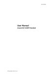
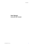
IP
Client
Unite module
Device Manager
Figure 1. Configuration of handsets via Device Manager in and chargers.
2.2.2
Over-the-air via IP-DECT
There is no external equipment needed besides Unite module and IP-DECT. Please proceed
with 3 Handset Maintenance on page 8.
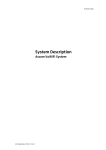
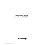
Ascom
IP-DECT
System
IP
Unite module
IPBS
Client
003
Device Manager
Figure 2. Configuration of handsets via Device Manager in the Unite module and overthe-air.
Figure 3.
2.3
Device Management in Multiple Systems
When a handset is used in multiple systems, the system that the handset synchronizes with
is determined by the Device Manager in the Unite module. This means that software
upgrades and handset configurations are only applied when it is present in the system
where the handset synchronizes with the Device Manager.
The default setting depends on two conditions:
31 October 2013 / Ver. H
6
Configuration Manual
Ascom d81 DECT Handset
•
•
2 Getting Started
TD 92674EN
if a handset has a valid subscription and is upgraded to software version 3.5.6 or
greater, the default setting is for the handset to synchronize with the Device Manager in
all systems.
if a handset has no subscriptions and is subscribed to the first system, the default,
setting is for the handset to synchronize with the Device Manager in that system, that is
System A.
NOTE: When changing the "Device Management system" parameter to another system, the
handset looses the connection to the IP-DECT system for a few seconds.
1
In the PDM or Device Manager, select the "Number" tab.
2
Select the handset to be configured.
3
In the Number menu, select "Edit parameters". A dialog window opens.
4
Select "Systems".
5
In the Device Management System drop-down list, select the system to be used for
device management.
31 October 2013 / Ver. H
7
Configuration Manual
Ascom d81 DECT Handset
3
3 Handset Maintenance
TD 92674EN
Handset Maintenance
This section describes the recommended procedures for installing and configuring handsets.
There are several ways to install a handset but the procedures described here guarantees
simple maintenance of the system.
The Device manager in the Unite module is the recommended method for installing,
upgrading, configuring and managing handsets in a large system because it allows large
numbers of handsets to be maintained simultaneously. Another benefit is that the recall
and collection of handsets from users is not required. The handsets can be maintained while
placed in network connected DC4 desktop chargers on users desks. Network connected CR3
charging racks can also be used, or over the air for IP-DECT.
The PDM is suitable for smaller systems where a handset is managed by inserting it in a DC4
Desktop Charger or CR3 charging rack connected via USB to a system administrator
computer.
For PDM, see its Installation and Operation Manual.
3.1
Preparing the PDM or Device Manager
If the parameter definition file (.def) for the handset is not present in the PDM or Device
Manager, it can be added by following the procedure below. The parameter definition file
and software file (.bin) are delivered as a package file with the extension .pkg. Note that
template files (.tpl) may also be included in a package file.
1
Open the PDM or Device Manager.
2
In the File menu, select Import > Packages.
3
Select the package and click "OK".
The package is imported and the files are created.
File extensions are further explained in an appendix in the corresponding Installation and
Operation Manual for PDM/the Unite module.
3.2
Installing a New Handset
The installation basically contains three steps:
•
•
•
Subscription to the IP-DECT system – needed to be able to make calls and send messages
(Mandatory).
Create an identity for the handset in the PDM/Device Manager – needed to be able to
configure the behaviour of the handset and take backups of the handset configuration
(Recommended).
Configure the handset using PDM/Device Manager – customize the behaviour of the
handset to suite each user profile and the specific PBX used in the system
(Recommended).
How to install the handset depends on the system to be used.
•
•
3.2.1 Handset Installation in IP-DECT System using Easy Registration on page 9
3.2.2 Handset Installation in DECT System (Manually) on page 9
31 October 2013 / Ver. H
8
Configuration Manual
Ascom d81 DECT Handset
3.2.1
3 Handset Maintenance
TD 92674EN
Handset Installation in IP-DECT System using Easy Registration
A handset can subscribe to an IP-DECT system automatically if the following are fulfilled:
•
•
•
•
The IP-DECT system is configured for Easy Registration, see the Installation and
Operational Manual for your IP-DECT system.
The handset’s extension number and IPEI are registered in the IP-DECT system, see the
Installation and Operational Manual for your IP-DECT system.
The handset is not subscribed to any systems.
The handset software is version 3.0.x or higher.
Subscribe
Subscribe the handset to the IP-DECT system. The subscription procedure is described in the
handset’s User Manual.
During the subscription procedure, the handset User ID is set automatically to the same as
the extension number. The User ID is used to identify the handset when it is connected to
PDM/Device Manager and is visible in the Number column.
Tip: The User ID can be viewed in the handset by navigating to the menu:
Admin menu > Device info > User ID.
See also examples of handset configurations that can be made in chapter 5 Handset
Configuration on page 18.
3.2.2
Handset Installation in DECT System (Manually)
NOTE: The handset to be installed must not have any previous valid registrations. If it has a
valid registration, unsubscribe the handset.
Subscribe
1
Assign an extension number for the handset in the DECT system. See the
corresponding manual for the DECT system.
2
Subscribe the handset to the DECT system. The subscription procedure is described in
the handset’s User Manual.
During the subscription procedure, the handset’s User ID is automatically set to the
same as the extension number. The User ID is used to identify the handset when it is
connected to PDM/Device Manager and is visible in the Number column.
Tip: The User ID can be viewed in the handset by navigating to the menu:
Admin menu > Device info > User ID.
See also examples of handset configurations that can be made in chapter 5 Handset
Configuration on page 18.
31 October 2013 / Ver. H
9
Configuration Manual
Ascom d81 DECT Handset
4.
4. Maintenance
TD 92674EN
Maintenance
4.1
Definitions
In the replacement descriptions, the handsets are defined as:
•
•
4.2
"old handset" is the handset to be replaced, possibly damaged but still working
"new handset" is the replacement handset that receives the settings used in the old
handset
Upgrade Handset Software
Handset software can be upgraded or reinstalled. When upgrading the software, data, such
as messages, may get deleted.
1
Open the PDM or Device Manager.
2
In the Devices tab, right-click the handset to be upgraded.
3
Select "Upgrade software...".
4
In the Available software drop-down list, select the desired software file (.bin).
If needed, import the software file to be used by clicking "Import". Locate the
software file (.bin or .pkg) and click "Open".
5
4.2.1
Click "OK".
Download Times during Upgrade of Handset Software
The software is downloaded to the handset. The following table shows the approximately
download times for handset when done over-the-air (OTA) in an IP-DECT system, or via
charger in a DECT system.
Table 1. Download times
OTA via IPBS
OTA via IPBL DC4 Charger connected DC4 Charger connected to PDM
to Device Manager via via USB.
Ethernet
approx. 25
min.
approx. 189
min.
approx. 9 min. 20 sec.
approx. 9 min. 30 sec.
The software download capacity depends on call traffic stated below. The table below is not
applicable for DC4 charger connected to PDM since IPBS, IPBL or Unite module is not needed.
Table 2. Download times during calls
IPBS/IPBL
0-4 simultaneous downloads depending on call traffic as follows:
No. of calls
31 October 2013 / Ver. H
No. of possible simultaneous downloads
0
4
1
3
2
2
3
1
4>
0
10
Configuration Manual
Ascom d81 DECT Handset
Device
Manager
4. Maintenance
TD 92674EN
Max. 10 simultaneous downloads (max. 20 when using an external web
server).
TIP: Several handsets of the same device type (d81) can be upgraded simultaneously using
the Baseline function in the Unite module. See the Installation and Operation Manual for the
Unite module.
4.3
View Handset License
The license(s) of a handset can be viewed as follows;
•
•
•
4.4
In idle mode, press *#34# and select "License", or
View the license(s) via the Admin menu in the handset, see 6.1 Admin Menu Tree on
page 61, or
In the PDM, select the "Licenses" tab and select handset in the list. In the bottom of the
work area, the license options of the device are listed, and whether the options are
enabled or not.
Upgrade Handset by License
Tip: It is recommended to read the Function Description, Product Licensing Overview, TD
92677GB before reading this section. The document describes how to view current
license(s), purchase license(s) and the technical solution of the upgrading alternatives
described below.
A handset can be upgraded to Protector and new functionality by adding a license key for
the new functions or variant.
There are three alternatives for upgrading a handset:
•
•
•
Automatic upgrade, see 4.4.1 Automatic License Upgrade on page 11.
License upgrade using import/export, see 4.4.2 License Upgrade Using Import/Export on
page 12.
Manual upgrade, see 4.4.3 Manual License Upgrade on page 12.
Note: A handset can be re-licensed up to 99 times.
The following functions are license dependent:
•
•
•
•
4.4.1
Shared Phone1, see 5.44 Shared Phone on page 57 for additional settings.
DECT Location, see 5.22 DECT Location and LF Location on page 33 for additional
settings.
Bluetooth Data Profile, see 5.46 Bluetooth Data Profile on page 59 for additional
settings.
Pull cord alarm, see 5.28 Pull-Cord Alarm on page 38 for additional settings
Automatic License Upgrade
Use this option if the PDM has an Internet connection to the License Server.
1
Place the handset in a charger connected to the PDM/Device Manager.
First time the handset logs on the PDM, the license key is automatically downloaded
to the handset, go to step 3.
1. Only applicable if the handset is used in a IP-DECT system.
31 October 2013 / Ver. H
11
Configuration Manual
Ascom d81 DECT Handset
2
4. Maintenance
TD 92674EN
If the handset has been logged on to the PDM/Device Manager before, no automatic
check for licenses is done. The PDM/Device Manager and License Server must be
synchronized as follows;
• Open the PDM/Device Manager.
• Select the "Licenses" tab.
• Right-click the handset in the list.
• Select "Refresh".
The license key is downloaded to the handset.
3
4.4.2
The handset is restarted. See also 4.3 View Handset License on page 11 for viewing
the handset’s license option(s).
License Upgrade Using Import/Export
Use this option if the PDM/Device Manager has no Internet connection to the License Server.
A device information file (.XML) must first be exported from the PDM, and then imported to
the License Web.
1
Place the handset in a charger connected to the PDM/Device Manager.
2
Open the PDM.
•
•
•
•
3
Select the "Licenses" tab.
Right-click the handset(s) in the list.
Select "Export".
Save the file on a computer with Internet connection to access the License Web
later on.
Access the License Web by entering the address "https://ascom-ws.com/licenses" in
a browser. The License Web is used for:
•
•
•
Importing the device information file
Viewing/Purchasing the license(s) for the handset(s)
Downloading the license file containing the license key(s) for the handset(s)
See the online help on the License Web, or the Function Description document
Product Licensing Overview for information on how to use the License Web.
4
When the license file (.XML) containing the license key(s) has been downloaded from
the License Web, select File > Import > Licenses in the PDM to import the file.
5
When the file is imported, the license key(s) is downloaded to the handset(s), and
the handset is restarted. See also 4.3 View Handset License on page 11 for viewing
the handset’s license option(s).
4.4.3
Manual License Upgrade
Use this option if the serial numbers of the devices cannot be exported to a file due to a
PDM/Device Manager is not in use. The serial number(s) must be manually entered in the
License Web to get the corresponding license key for the handset. The license key must also
be manually entered in the handset. See the online help on the License Web or the Function
Description document Device License Overview for information on how to get a license key.
Tip: If several handsets are to be upgraded, it is recommended to use 4.4.2 License Upgrade
Using Import/Export on page 12.
The license key is added via the Admin menu in the handset, see 6.1 Admin Menu Tree on
page 61 for information on how to activate the Admin menu.
Tip: The keys *#35# can also be pressed in idle mode for quick access to the "Enter license
key" menu.
1
Press the soft key "Menu".
31 October 2013 / Ver. H
12
Configuration Manual
Ascom d81 DECT Handset
4. Maintenance
2
Select "Calls".
3
Select "Admin menu".
4
Select "Enter license key".
5
Enter license key without any spaces between the digits.
6
Press "OK".
TD 92674EN
If the license key is valid, a dialog window "License key accepted" is shown. The handset is
restarted.
4.4.4
Move License
Note: This feature requires that the Device Manager supports the move license feature, and
a connection to the license server.
A license can be moved from one d81 device to another device of the same type.
A move license command can only be done to an unlicensed handset of a device type
supporting licensing, that is, d81 Messenger.
Note: A Bluetooth Data Profile license can only be moved to a handset with Bluetooth. In
addition, a Shared Phone license can only be moved to a IP-DECT handset.
An example of when to use the Move license command is when there is an unused d81
Messenger and a d81 Protector with a broken display. Use the Move license command to
move the Protector license to the d81 Messenger which becomes a d81 Protector. Then the
broken handset (which is now a d81 Messenger) can be sent for service.
1
Select the “Licenses” tab.
2
Select the device whose license is to be moved. The selected row is highlighted.
3
In the License menu, select “Move license...” or right-click and select “Move license...”.
The Move license window appears.
4
Select the device that shall receive the license. Click "OK".
If no devices are shown in the Move license window, there are no devices that are
selectable to move the license to.
The device whose license that has been moved has now become a d81 Messenger. The
device that received the license is still shown as a d81 Messenger. Select this device and do
the following:
5
In the Licenses menu, select "Refresh" to complete the transfer of the license. The
device is now a d81 Protector.
See also 4.6 Replacement Procedure Choice Guide on page 14 for information on how to
move user parameters and contacts to another handset.
4.5
Perform a Factory Reset
When a factory reset is done on a handset, all configuration settings are restored to their
default values and PBX subscriptions and all data are removed. This includes contacts,
messages etc. The software is left intact.
Factory Reset using PDM/Device Manager
1
In PDM or Device Manager, click the Device tab and mark the handset to be factory
reset. Note that the handset must be online.
2
In the Device menu, select "Factory reset". Alternatively, right-click the handset and
select "Factory reset".
31 October 2013 / Ver. H
13
Configuration Manual
Ascom d81 DECT Handset
3
4. Maintenance
TD 92674EN
A Reset devices dialog appears, click "Yes". The handset is restarted.
Factory Reset using Handset
A factory reset can be performed from the handset Admin menu.
4.6
1
To activate the Admin Menu, enter the Call time screen and press > * < < * <.
2
Select "Factory Reset".
3
A Reset portable? dialogue appears, press "Yes". The handset is restarted.
Replacement Procedure Choice Guide
Depending on situation, two different replacement procedures can be chosen; replacement
via PDM/Device Manager and Easy Replacement. Use the following list as a guide to choose
which procedure to use.
•
•
•
4.7
If a handset needs to be replaced due to for example a broken display, see the handset’s
User Manual.
If the electrical connection is damaged, it might not be possible to follow the Easy
Replacement procedure. Depending on fault, it might work to do a replacement via PDM/
Device Manager, see 4.7 Replacement of Handset with Device Manager on page 14 or 4.8
Replacement of the Handset with PDM on page 15.
If two handsets and their settings are switched between two users, follow 4.7
Replacement of Handset with Device Manager on page 14 or 4.8 Replacement of the
Handset with PDM on page 15.
Replacement of Handset with Device Manager
Both the old handset and the new handset must be of the same device type. The same
extension number is assigned to the new handset.
Make sure that the old handset is saved in the Device Manager. Start the Device Manager
and navigate to the "Numbers" tab. There is a
in the Saved column for the old handset.
If the handset is not saved, insert it into a desktop charger or charging rack connected to
Device Manager and perform a save, see the Installation and Operation Manual for the Unite
module.
If the old handset settings cannot be saved, stop the replacement procedure. Instead
unsubscribe the old handset from the PBX, register the new handset and follow the
instructions for installing a handset, see 3.2 Installing a New Handset on page 8.
When the handset is saved, unsubscribe the old handset from the PBX. The following steps
are described for two different scenarios. Check the most suitable before proceeding.
4.7.1
Data Included in a Replacement Transfer
The following data is replaced during a replacement with Device Manager:
•
•
User parameters (including User ID)
Contacts (entered by the user)
Note that the following data is not replaced:
•
•
DECT registration
Call list
31 October 2013 / Ver. H
14
Configuration Manual
Ascom d81 DECT Handset
•
•
•
•
•
4.7.2
4. Maintenance
TD 92674EN
Messages
Bluetooth pairing list
Company phonebook
Downloaded Language
Licenses1
Handset Replacement with Device Manager in DECT System
NOTE: The replacement handset must not have any previous valid registrations. If it has a
valid registration, unsubscribe the handset.
1
Unsubscribe the old handset. If the unsubscribtion cannot be performed in the
handset, unsubscribe the handset via the DECT interface. See the corresponding
documentation for your system.
2
Subscribe the new handset with the same extension number as the old handset. The
subscription procedure is described in the handset’s User Manual. During the
subscription procedure, the handset’s User ID is automatically set to be the same as
the extension number.
TIP: The User ID can be viewed in the handset by navigating to the menu:
Admin menu > Device info > User ID.
3
Insert the handset into a desktop charger or charging rack connected to Device
Manager (not needed if an over the air connection is used). Navigate to the Numbers
tab in the Device Manager.
The new handset now has the same User ID as the old handset. It is automatically
synchronized and data and parameter settings from the old handset are transferred
to the new handset.
The synchronization takes a while if the Contacts in the original handset contains a
large number of entries.
4.8
Replacement of the Handset with PDM
To see which data that is replaced during this process, see 4.7.1 Data Included in a
Replacement Transfer on page 14.
Both the old handset and the new handset must be of the same device type. The same
extension number is assigned to the new handset.
The new handset should not yet be subscribed to the PBX.
1
If the new handset has been previously used, perform a factory reset, see 4.5 Perform
a Factory Reset on page 13.
2
Make sure that the handset is saved in the PDM. In the Numbers tab, a saved handset
in the Saved column. If not, right-click the handset and select
has the symbol
"Save" to transfer the settings to the new handset later on.
Note: If the old handset settings cannot be saved, stop the replacement procedure. Instead
register the new handset and follow the instructions for installing a handset, see 3.2
Installing a New Handset on page 8.
The following steps are described in two different scenarios. Check the most suitable one
before proceeding.
1. A handset’s license can be moved using the Move license function in the Device Manager.
31 October 2013 / Ver. H
15
Configuration Manual
Ascom d81 DECT Handset
4.8.1
4. Maintenance
TD 92674EN
Handset Replacement with PDM in DECT System
NOTE: The handset to be installed must not have any previous valid registrations. If it has a
valid registration, unsubscribe the handset.
1
Unsubscribe the old handset. If the unsubscribtion cannot be performed in the
handset, unsubscribe the handset via the DECT interface. See the corresponding
documentation for your system.
2
Subscribe the new handset with the same extension number as the old handset. The
subscription procedure is described in the handset’s User Manual.
During the subscription procedure, the handset’s User ID is automatically set to the
same as the extension number. The User ID is used to identify the handset when it is
connected to PDM and is visible in the Number column.
TIP: The User ID can be viewed by navigating to the menu:
Admin menu > Device info > User ID.
3
Insert the new handset into a desktop charger or charging rack connected to the
PDM.
4
A dialog window appears, asking the user to decide whether to use the Number
settings in PDM or the Number settings in the device. Select "PDM".
The handset is automatically synchronized and all data and parameter settings are
transferred to the new handset. The synchronization takes a while if the Contacts in
the original handset contain a large number of entries.
4.9
DECT Frequency Band Configuration
NOTE: The frequency band configuration is only needed if other frequencies than EU US
China is used. Additionally, if the handset has been returned from repair, the applicable
frequency band might be set again.
To change the operating frequency band, the following preconditions must be fulfilled:
•
•
The frequency is set to Not initiated. This can be checked by entering the Admin menu,
see 6 Administration on page 61, follow the path:
Admin menu > Device info > Hardware.
Scroll down to “Frequency band”.
The handset must not have a DECT registration. If it already has, perform a Factory reset,
see 4.5 Perform a Factory Reset on page 13.
1
Enter the Admin Menu, see 6 Administration on page 61.
2
Select "Frequency band" and select the desired band.
•
•
•
•
•
EU US China (default)
LA (Latin America)
Brazil
1900 - 1920 MHz
Multifrequency (see also 4.9.1 Multiple Frequency Support)
3
Restart the handset.
4
Register the handset.
5
The frequency band option is no longer available.
NOTE: The selection is persistent and can withstand a factory reset.
31 October 2013 / Ver. H
16
Configuration Manual
Ascom d81 DECT Handset
4.9.1
4. Maintenance
TD 92674EN
Multiple Frequency Support
The handset can be used in a system that changes frequency by selecting “Multifrequency”
as frequency band in the handset. See 4.9 DECT Frequency Band Configuration. This setting
is applicable for handsets used in different regions of the world. For example for users
working on a ship that visits different countries.
When the frequency band is set to "Multifrequency", the handset adapts to the applicable
frequency band (EU, US or Brazil) used in the specific region after it has been restarted.
NOTE: The handset adapts to the frequency band configured in the DECT system.
The recommended procedure when changing frequency band is as follows:
1
The site administrator sends out broadcast message to all handsets informing that
the handsets need to be restarted at a specific time.
2
The site administrator enters IP-DECT master and change setting for the frequency
and carriers just before the specific time.
3
All handset users restart their handsets.
After the restart the handsets have changed to the applicable frequency band (EU, US or
Brazil).
31 October 2013 / Ver. H
17
Configuration Manual
Ascom d81 DECT Handset
5
5 Handset Configuration
TD 92674EN
Handset Configuration
Note: This chapter describes settings in parameter definition files (.def). These files are
regularly updated and settings may change slightly. For example "On" to "Enable" or a
parameter can be moved to another directory.
5.1
Configure a Handset with a Template
A template contains one or more parameter settings. By using a template, the same
configuration can easily be applied to many handsets simultaneously. Templates are also an
efficient way to give good control over which changes that are applied to each handset.
Templates enables configuration of all aspects of a handset from sound volume to keypad
short cuts.
Your supplier can provide example templates for different PBX:s. The handset has full
functionality to the PBX even without such a template. By using such a template, though,
the handset is customized for that PBX with menu options for PBX specific functions such as
Callback.
A template can be created (see 5.1.1 Create a Template) and/or imported (see the
Installation and Operation Manual for PDM/Device Manager.
5.1.1
Create a Template
1
Open the PDM or the Device Manager.
2
In the Templates tab, select Template > New. The Create Template window is opened.
3
Select the device and parameter version that matches the software version installed
on the handset. Give the template a descriptive name.
The parameters that are not part of the template is left unchanged on the handset.
The parameter version of an installed handset is visible under the Numbers tab or the
Devices tab.
4
Select the checkbox of each parameter that you want to be part of this template and
enter the proper value.
5
Click "OK" to save your template.
31 October 2013 / Ver. H
18
Configuration Manual
Ascom d81 DECT Handset
5.1.2
5 Handset Configuration
TD 92674EN
Apply a Template
1
Open the PDM or the Device Manager.
2
In the Numbers tab, right-click the handsets you want to apply the template to.
3
Select "Run template...".
Only templates with a parameters version matching the selected handsets are
shown. Select the template you want to apply and click "OK".
The template is applied. The number of parameters in the template affects the time it
takes to apply the template to the selected handsets.
When looking at a handset under the Numbers tab, the column Last run template
shows the name of the most recently applied template.
Tip: A template can be applied to several handsets of the same d81 device type
simultaneously using the Baseline function in the Device Manager. See Installation and
Operation Manual for the Unite module.
5.1.3
Save a Handset Configuration as a Template
All handset settings can be saved as a template. Note that this does not include contacts
and other personal data. The template contains only configuration data.
This template can be used as a backup if the handset configuration needs to be restored at
a later stage or as a template that can be applied to a number of handsets.
1
Some parameters are user specific. If it is decided to apply this type of template to
several handsets, it is recommended to exclude the following parameters:
•
2
Owner ID - A text string specified in idle mode. The parameter is located directly
under "Settings".
• Phone lock PIN code - The security code used to unlock the keypad. The parameter
is located under Settings > Locks.
Open PDM or the Device Manager.
3
In the Numbers tab, right-click the handset you want to save as a template.
4
Select "Use as a template...". Enter a descriptive name for the template.
5
The Edit template window is opened. By default, all parameters are selected and are
saved when clicking on "OK".
If one or more parameters should be excluded, remove them by clearing the checkbox
next to the parameter.
6
5.1.4
Click "OK".
Synchronizing a Handset with PDM/Device Manager
After installing and saving, the handset is synchronized every time it is connected to the
PDM. The synchronization transfers parameter changes between the handset and the PDM
and vice versa as follows:
•
If a parameter has been changed in the handset, it is transferred to the PDM/Device
Manager.
• If a parameter has been changed in the PDM/Device Manager while the handset was
disconnected, it is transferred to the handset.
If the same parameter has been changed in both the PDM/Device Manager and the handset,
the value in PDM/Device Manager is transferred to the handset.
31 October 2013 / Ver. H
19
Configuration Manual
Ascom d81 DECT Handset
5.2
5 Handset Configuration
TD 92674EN
Voicemail
In some systems it is needed to assign the handset number of the Voicemail service. The
parameter can be set specifically for each PBX subscription on the handset and is accessed
from Systems > System x > PBX Settings > Numbers. "System x" is replaced with the
subscription (System A - System H) that is configured.
5.2.1
Wildcard Characters in Voicemail Number
When programming voicemail dial strings in PDM/Device Manager, a wildcard character, N,
can be used to represent the phone extension number.
For example, a PBX uses voicemail numbers that are a combination of a base voicemail
number and the phone extension number. If the base voicemail number is 2222 and the
extension number is 4455, the voicemail number is 22224455. Using the N wildcard
character this can be written as: 2222N
5.3
Central Phonebook
If the system is equipped with a messaging server with a phonebook service, the Central
Phonebook on that server can be accessed from the handset. The number to be used is set
to default 999999. It can be changed by editing parameters in a Number or a template.
If the system is not equipped with a Central Phonebook, this menu option can be removed
from the handset by entering an empty value for the corresponding parameter.
The parameter can be set specifically for each PBX subscription on the handset and is
accessed from Systems > System x > PBX Settings > Numbers. "System x" is replaced with
the subscription (System A - System H) that is configured.
5.4
Company Phonebook
A phonebook can be created that is centrally managed and uploaded to the handset from
PDM/Device Manager. If this feature is used, entries from Contacts and Company Phonebook
are merged. The Company Phonebook entries are locked and cannot be edited in the
handset.
1
Create a Company phonebook file.
2
Import the Company phonebook file to PDM/Device Manager, see the corresponding
Installation and Operation Manual.
3
Upload the company phonebook file to the handset(s) via PDM/Device Manager, see
the corresponding Installation and Operation Manual.
5.4.1
Create a Company Phonebook File
The phonebook file (.cpb) is created from an Excel file using a script to extract the
information and create to the phonebook file (.cpb). The Excel file is provided by your
supplier.
The handset supports a maximum length of 24 characters in each field, additional
characters are truncated when the phonebook file is created. The following characters are
accepted in the handset number field in the phonebook file, but are ignored when the
phonebook file is created: "(", ")", "-" and " "(space).
31 October 2013 / Ver. H
20
Configuration Manual
Ascom d81 DECT Handset
5.4.2
5 Handset Configuration
TD 92674EN
Upload a Company Phonebook File
In PDM/Device Manager, go to the devices tab and select device(s). In the Device menu,
select "Upload phonebook".
5.4.3
Delete Company Phonebook Entries
Company phonebook entries in a handset can be deleted by downloading an empty
company phonebook file to the handset.
5.5
Import Contacts
A contact file can be created that is centrally managed and uploaded to the handset from
PDM/Device Manager.
5.5.1
Create a Contact File
The contact file is created by an Excel file provided by the handset supplier.
5.5.2
Upload a Contact File
NOTE: When uploading a contact file, the entries in the handset are replaced by the entries
in the file.
5.6
1
In PDM or the Device Manager, go to the Numbers tab and select handset(s).
2
In the Number menu, select Import contacts > From file.
3
Select the file to be imported and click "Open".
Call Services
Call services is a configurable menu in the handset. Its purpose is to provide a user friendly
access to system dependent functionality such as absence handling and call diversion.
The menu is described in the handset’s User Manual.
In addition to the default Call services functions, up to 10 extra system specific call services
by codes can be defined. The codes can be programmed in the following ways:
•
•
•
with the digits 0-9
with the special characters # and *
With the following uppercase characters:
P – pause
H – hook, that is, auto disconnection
U – the handset prompts the user to enter numerical characters to make a procedure
call.
Using the PDM/Device Manager and the "Edit template" feature, the parameter can be
found at
Systems > Common > Call Services > General Service X
Contact the handset supplier for an example template to configure the call services menu
for the PBX.
31 October 2013 / Ver. H
21
Configuration Manual
Ascom d81 DECT Handset
5.6.1
5 Handset Configuration
TD 92674EN
Activate or Deactivate Call Services when Changing Profile
A call service can be activated or deactivated when changing profile in the handset. This
feature can for example be used to send feature access codes (for example *21*) to the
system when the handset changing profile.
1
If needed, configure the Call services to be used for the profiles, respectively. See 5.6
Call Services.
2
Select User Profiles > User Profile X (where X represents 1 - 4).
3
Select Presence and diversion > Call services.
4
In the When activated and When deactivated drop lists, select the Call services to be
used when the profile is activated and deactivated.
TIP: A profile can be activated when placing a handset in a charger, see 5.15 Actions when
Handset Placed in Charger on page 29.
5.7
Call Diversion
User friendly call diversion menus can be configured in the handset using PDM/Device
Manager. These menus can then be selected in the handset by selecting Calls > Call services
> Divert calls.
Tip: In addition to the default call diversion menus, up to define 10 extra system specific
services codes can be defined. See 5.6 Call Services.
1
Select Systems > System X (where X represents A - H).
2
Select PBX Settings > Diversion.
3
Select "Internal", "External", "On No Reply", "On Busy", and/or "All Calls"; enter the
following:
•
•
•
Prefix - the system specific prefix code to be used (if required by the PBX used)
Suffix - the system specific code required to activate the diversion (for example
"*21*")
Cancel - the system specific code required to deactivate the diversion (for
example "#23#").
The user can now enter the diversion number in the handset.
5.7.1
Call Diversion in Profiles
A handset can be configured to divert calls when a certain profile is activated.
NOTE: The PBX settings for call diversion must also be configured, see 5.7 Call Diversion.
1
Select User Profiles > User Profile X > Presence and diversion.
2
Select which calls to be diverted (that is all call, internal calls etc.).
3
In the Divert calls to field, enter the phone number where the calls are diverted to
when the profile is activated.
4
Select "User Profile X".
5
In the Name field, enter an appropriate name of the profile.
Additional settings can be added for a profile, such as soft keys, sound and alert etc. See
5.42.1 User Profiles on page 53.
31 October 2013 / Ver. H
22
Configuration Manual
Ascom d81 DECT Handset
5.8
5 Handset Configuration
TD 92674EN
Absence Handling
User friendly absence menus can be configured in the handset using PDM/Device Manager.
These menus can then be selected in the handset by selecting
Calls > Call services > Absence.
This menu is used to set the reason why a call cannot be answered, for example when you
are in a meeting. The caller is notified about the absence reason when calling.
Beside the default absence menus, up to 10 extra system specific services codes can be
defined, see 5.6 Call Services.
1
Select Systems > System X (where X represents A - H).
2
Select PBX Settings > Absence.
3
Select "Common codes", enter the following:
Activation prefix - the system specific activation prefix code required to activate
the absence (for example *23*)
• Activation suffix - the system specific activation suffix code required to activate
the absence (for example #)
• Deactivation - the system specific code required to deactivate the absence (for
example "#23#").
• PBX date format for user input - the PBX supported date format to be sent to the
PBX when activating an absence reason containing a date (for example
"Vacation"). The date in the handset is always entered in MMDD format. If the
parameter is set to DDMM, the handset automatically converts to correct date
format.
Select "Lunch", "Meeting", "Trip", "Vacation", "Out" and/or "General absence X"; enter
the following:
•
4
•
•
•
5.9
Activation code - the system specific code for an absence reason, for example
"0*".
Name - enter name of absence reason (only for General absence). The name is
visible in handset.
User input - specifies if time or date is required for the absence reason (only for
General absence).
In Call Menu
The In Call menu let a user access a number of functions during a call. Some functions are:
•
•
•
5.9.1
Always displayed
Normally displayed
Advanced functions that may be included by the administrator.
Always Displayed
The following functions are always accessible during a call:
Function
Description
Messaging
Displays the "Messaging" menu and messaging functions available
during a call.
Microphone
Turn the microphone on or off
The Messaging function may be hidden from the In Call menu in the following way:
1
Navigate to Customization > Visibility > Messaging
31 October 2013 / Ver. H
23
Configuration Manual
Ascom d81 DECT Handset
2
5 Handset Configuration
TD 92674EN
Set the value of the Messaging parameter to "Hide".
NOTE: The Messaging parameter may also be set to “Read only”. This allows the user to
access the messaging function during a call but does not allow the user to delete sent
or received messages.
The Microphone function cannot be hidden or removed from the In Call menu.
5.9.2
Normally Displayed
These functions in this are normally displayed during calls. The administrator can add or
remove a function from the In Call menu by selecting "Edit parameters" in the PDM/Device
Manager or by opening and editing the template file from the PDM "Templates" tab:
Function
Description
New call
Start a new call during a conversation
End current call
End a call from the In Call menu
Switch call
Switch between calls
Transfer call
Transfer a call
Conference call
Make a conference call
Transfer to new
Performs an unattended transfer of the inbound call to another party
Callback
May be requested if the user is engaged. When the user becomes
available, the calling party receives a callback from the PBX
Call waiting
May be requested if the user is already on a call. Notifies the user
that a call is waiting
Contacts
Open the handset contacts list
DTMF
When requested, enables the handset to send DTMF
Decline call waiting Determines what is sent to PBX when user declines an incoming call
during the current call
To locate the function and configure the associated parameter:
1
Navigate to System > System X > PBX Settings > In call functionality > <parameter
name> <value>
2
To remove the function from the In Call menu, delete the value of the parameter
associated with the function. To add a function that is not displayed, set the
parameter value associated with the function.
5.9.3
Advanced Functions
The administrator can configure the handset to allow access to the following advanced
functions during a call. These are functions intended for an advanced user such as an
installer using the handset to measure RF link and system parameters as part of a
troubleshooting or site surveying procedure.
Function
Description
DECT Info
Shows link and DECT system information
31 October 2013 / Ver. H
24
Configuration Manual
Ascom d81 DECT Handset
5 Handset Configuration
TD 92674EN
Function
Description
Location Info
Shows location IDs and RSSI values received from location devices if
the handset has the appropriate DECT Location license and a DECT
location service is running
These functions can be added to the handset In Call menu by activating the Admin Menu as
described in 6.1.1 Activating the Admin Menu on page 61.
5.9.4
Configuring Own In Call Functions
Up to 10 extra system specific call services by codes can be defined. The codes can be
programmed as follows:
•
•
•
•
•
with digits 0-9,
The characters #, *,
P – Pause
H – Hook (auto disconnection)
U – the handset prompts for user input. Numerical characters may also be entered as
input (procedure call).
To define a system specific call service:
1
Select Systems > System X > PBX Settings > In call functionality > General purpose X
2
In the Name field, enter the name to be displayed in the In call menu.
3
In the Data field, enter the applicable code to be used for the function.
4
Click "OK" to save the settings.
Tip: The handset supplier may have a template example that configures the In call functions
menu for the PBX.
5.9.5
Create or Hide a Soft Key to an In Call Function
The left or right Soft keys can be configured to be hidden or as shortcuts to a certain In call
function. By default, the left Soft key is configured as a loudspeaker key and the right Soft
key is configured as R-key.
Create a Soft Key to an In Call Function
1
If needed, configure the In Call functionality to be used. See 5.9 In Call Menu on page
23. This is not needed if the Loudspeaking function or R-key is used.
2
Select Systems > System X > PBX Settings > In call functionality > Soft key X
3
In the Name field, enter a descriptive name of the Soft key. This is not needed if the
functions Loudspeaking or R-key is used.
4
In the Function drop-down list, select the function to be used:
R-key
Loudspeaker
Turn the loudspeaker on or off
during the call.
New call
Dial an additional call during an
ongoing call.
End current call
A current call can be ended when
having to two calls established.
Switch calls
Switch between two established
calls.
31 October 2013 / Ver. H
25
Configuration Manual
Ascom d81 DECT Handset
5
5 Handset Configuration
TD 92674EN
Transfer a call
Transfer the current call to the other
call that is on hold.
Transfer to a new call
Transfer the current call to a new
call.
Callback
Automatically call back to a busy
number when it is free.
Call waiting
Answer another call during an
ongoing call.
General purpose 1 -10
Own defined In call services
Click "OK" to save the settings.
Hide a Soft Key to an In Call Function
1
Select Systems > System X > PBX Settings > In call functionality > Soft key X
2
In the Function drop-down list, select "Not used".
3
Click "OK" to save the settings. The Soft key is not visible during a call.
5.10 Own Line Settings
Use the own line settings when it is desired to use the same phonebook in different systems
and in different countries.
The own line settings enables:
•
•
Calling numbers stored with a "+" sign for the international access code. The same
phonebook can be used in different countries.
Recognizing incoming internal or external calls as numbers stored on international
format in the phonebook. The same phonebook can be used in different systems.
For this feature to work, numbers must be stored in the phonebook in international format
with a "+" sign for the international access code. The Own Line parameters must also be
configured via PDM/Device Manager.
5.11 Configure DTMF
Some legacy systems and PBXs require that the handset sends DTMF tones when pressing
or releasing the PTT button and/or when pressing the On-hook key to end a call.
5.11.1 Send DTMF Tone when Pressing On-Hook key
1
Select Settings > DTMF.
2
In the On-hook DTMF tone drop-down list, select the DTMF tone to be sent when the
On-hook key is pressed.
To disable the DTMF tone, select "Not used".
5.11.2 Send DTMF Tones when Pressing/Releasing the PTT Button
1
Select Settings > DTMF.
2
In the Push to talk DTMF tones drop-down list, select "On".
3
In the PTT DTMF ton on push drop-down list, select the DTMF tone to be sent when
pressing the PTT button.
31 October 2013 / Ver. H
26
Configuration Manual
Ascom d81 DECT Handset
4
5 Handset Configuration
TD 92674EN
In the PTT DTMF ton on release drop-down list, select the DTMF tone to be sent when
releasing the PTT button.
To disable the DTMF tones, select "Off" in the Push to talk DTMF tones drop-down list.
5.12 Uploadable Language
An additional language can be uploaded to the handset. The language file is generated via
an Excel file available from the handset supplier.
Note: If another language file is uploaded, the first additional language is overwritten.
Certain special characters are allowed when generating the language file, see information in
the Excel file.
To upload an additional language, the PDM/Device Manager is used, go to the devices tab
and select handset(s). In the Device menu, select "Upload language...".
A parameter can be altered to match the uploaded language. The parameter controls:
• The characters available for text input
• The sort order in the phonebook.
This parameter is only used when Language is set. The parameter can be found in the
"Settings" folder.
5.13 Personalizing the Menu
The handset menu can be customized by turning certain menus On or Off. This is done in the
PDM/Device Manager by editing a template (or a Number setting) for the corresponding
handset (or Number).
The path to these settings in the template depends on the version of the parameter
definition file (.def). In the current version the path is:
Customization > Visibility > X
where "X" can be Messaging, Favourites, etc.
The parameters are found under "X".
The settings for the parameters may have three alternatives, such as:
•
•
•
Show
Hide all
Read only (All settings can be viewed but not modified by the handset user)
5.13.1 Show or Hide Missed Call Window
A missed call is by default indicated by a Missed call window. The window can be hidden and
this is recommended if a user has, for example, both a handset and a mobile.
Example:
If configured in the PBX, an incoming call to the handset can either be answered using the
handset or mobile. If the user answers the call using the mobile, the Missed call window is
not displayed in the handset.
1
Select Settings > Answering.
31 October 2013 / Ver. H
27
Configuration Manual
Ascom d81 DECT Handset
5 Handset Configuration
TD 92674EN
5.14 In the Show missed calls popup drop-down list, select "No" to hide the Missed call
window.Configure Handset Restrictions
5.14.1 Enable or Disable Mute Function
The user can be prevented from muting a handset in the following way:
1
Select Customization > Phone restrictions
2
In the Turn off sound drop-down list, select one of the following:
•
•
Yes - The mute restriction is disabled.
No - The user is not able to mute the handset or set the ring volume to silent.
5.14.2 Enable or Disable Switch Off Function
The user can be prevented from switching off the handset in the following way:
1
Select Customization > Phone restrictions
2
In the Switch off handset drop-down list, select one of the following:
•
•
Yes - The user is not able to switch off the handset by pressing the On-hook key.
No - The switch off restriction is disabled.
5.14.3 Enable or Disable Call List
The handset can be prevented from storing outgoing and incoming calls in the call list. This
can be useful to prevent an unauthorized person from viewing the call list.
1
Select Customization > Phone restrictions
2
In the Enable call list drop-down list, select one of the following:
•
•
Yes - The handset stores the calls in the call list
No - The handset does not store calls in the call list
NOTE: Old incoming and outgoing calls are not deleted from the call list when setting the
parameter to No. It is recommended to clear all call lists to ensure that no old calls are
stored.
5.14.4 Enabling or Disabling Handset Keys
The handset keys 0-9, * and # are enabled by default so that users can press keys to dial
numbers, create messages, access soft keys and perform other supported system and
handset functions. However, certain application areas may require that users are prevented
from accessing all or some of the functions, so that when a user presses the key, nothing
happens. To access the parameters associated with the keys, perform the following steps:
1
Select Customization > Phone Restrictions
2
Select the required parameter:
Enable keys 0-9: Enable or disable numeric keys 0 through 9
Enable key star (*): Enable or disable the * key
Enable key hash (#): Enable or disable the # key
31 October 2013 / Ver. H
28
Configuration Manual
Ascom d81 DECT Handset
3
5 Handset Configuration
TD 92674EN
From the drop-down menu associated with each parameter, select one of the
following:
•
•
Yes - Retain the default, that is, the selected keys are enabled
No - Disable the selected keys, thereby denying the user access to the handset or
system functions associated with the keys.
5.14.5 Allow or Disallow Advanced Call Functions
The handset is enabled, by default, to let the user access the functions described in 5.9 In
Call Menu on page 23 during a call. The user can be prevented from accessing these
functions by not displaying the "More" softkey during the call. To access and configure the
parameter associated with the display of the call functions, perform the following steps:
1
Select Customization > Phone Restrictions
2
Select the Allow advanced call functionality parameter.
3
From the drop-down menu associated with the parameter, select one of the
following:
•
•
Yes - Retain the default and allow the user to access call functions
No - Prevent the user from accessing call functions.
5.14.6 Allow or Disallow Incoming Messages
The handset is enabled, by default, to receive text messages unless explicitly configured not
to do so. Whether or not incoming text message are allowed is determined by the value of
the Allow incoming messages parameter, which is set in the following way:
1
Select Customization > Phone Restrictions
2
Select the Allow incoming messages parameter.
3
From the drop-down menu associated with the parameter, select one of the
following:
•
•
•
Yes - Retain the default and allow incoming text messages to be received
No - Disallow incoming text messages from being received.
5.15 Actions when Handset Placed in Charger
5.15.1
Action when not in Call
The handset can be configured to perform an action when it is placed in a charger. The
selected action is only performed when no call is established. When the handset is removed
from the charger, it returns to previous settings.
NOTE: If the Logout action is enabled, the handset needs to be logged in manually when it is
removed from the charger.
1
Select Connections > In Charger
2
In the In charger action drop-down list, select one of the following:
•
•
•
No action - no action is performed when handset is placed in charger
Switch off - the handset is switched off when placed in charger
Redirect - the handset redirects all calls and messages when placed in charger.
NOTE: The destination number must be programmed in the PBX to be able to
31 October 2013 / Ver. H
29
Configuration Manual
Ascom d81 DECT Handset
5 Handset Configuration
TD 92674EN
redirect calls/messages.
•
Logout - the handset is logged out when placed in charger. This option is only
visible if the license dependent Shared Phone feature is enabled.
•
Message absence - if a message is sent from a system, it is notified that the
handset is absent.
•
Change profile - the handset changes profile when placed in charger.
In the Change to profile drop-down list, select the profile to be used. By default,
only the profile Normal is selectable. If configured, additional profiles are visible,
see 5.42.1 User Profiles on page 53.
•
Sound off1 - the handset is silenced when placed in charger.
NOTE: Breakthrough messages with high or alarm priority are not muted. To mute
all messages, regardless of priority, also set the Show and indicate incoming
messages parameter.
Show and indicate incoming messages (while charging)
Determines how incoming messages are displayed and indicated when the
handset is placed in charger. If this parameter is set to No, the message alert is
muted and only the New message icon is displayed. The messages are stored as
unread messages in the Messaging Inbox.
NOTE: All incoming messages are affected by this setting; that is PTT invitation
received as message, and all other messages regardless of priority, including
breakthrough messages with high or alarm priority. To silence non-breakthrough
messages with a low or normal priority, set the Sound off parameter instead.
•
5.15.2 In Charger Action when in Call
The handset can be configured to end a call, or turn on the loudspeaker when it is placed in a
charger during a call. If the handset is removed from the charger during the call, it does not
revert to the previous settings.
1
Select Connections > In Charger
2
In the Call behaviour drop-down list, select one of the following:
•
•
•
No action - no action is performed when handset is placed in charger
End - the handset disconnects calls when placed in charger.
NOTE: Some systems and PBXs require the handset to send a DTMF tone to end a
call, See 5.11.1 Send DTMF Tone when Pressing On-Hook key on page 26 for
configuration.
Put on Loudspeaker - the handset activates the loudspeaker mode when placed in
charger.
5.16 Clear Lists when Inserted in Charger
The handset can be configured to clear lists when placed in a charger. The following
message and call lists are then cleared:
•
•
•
•
•
Inbox
Unsent
Sent
Call list
Missed calls
1.If the parameter "Turn off sound" is set to "No", the device is not muted when placed in charger.
31 October 2013 / Ver. H
30
Configuration Manual
Ascom d81 DECT Handset
5 Handset Configuration
TD 92674EN
Using the PDM/Device Manager and the "Edit template" feature, the parameter can be
found at
Connections > In_Charger > Clear_Lists_In_Charger
in a template or parameter definition file (.def).
The default setting for "Clear list in charger" is "Off". The feature is activated by changing
the parameter value to "On". When the feature is enabled, the lists are cleared when the
handset is placed in the charger.
The next section only applies to Ascom d81 and Mitel 5607
5.17 Handset Locks
The PDM/Device Manager can be used to configure the following handset locks:
•
•
Automatic keypad lock
Phone lock.
Configuring the Keypad Lock
Handsets can be configured with a keypad lock to minimize the risk of accidentally pressing
keys or buttons while the handset is not in use. The key lock is applied after the handset has
been out of use for a specified time defined by the "Automatic lock time" parameter.
The locking and unlocking characteristics of the keypad can be defined by configuring
following parameters in the PDM/Device Manager and navigating to Settings > Locks:
•
•
•
Automatic key lock. One of the following options may be configured:
"On": the keypad is automatically locked if it is not used for the specified interval.
"On, except calls": the keypad is automatically locked if it is not used for the specified
lock time. If the user is on a call when the lock time elapses, the keypad remains unlocked
until the user has completed the call.
"Off": the keypad is never automatically locked.
Automatic lock time: specifies the time that elapses before the keypad is automatically
locked. The shortest time that may be specified before the key lock is applied is 5
seconds and the longest time is 3 minutes.
Automatic key unlock: the keypad is automatically unlocked when a call or message is
received. When the user has serviced the call or message, the key lock is reapplied after
the specified automatic lock time expires.
Configuring the Phone Lock
The handset can be protected for unauthorized use by activating the phone lock. If this
function is activated a PIN code has to be entered at power on, or when the handset is
removed from the charger.
The locking and unlocking characteristics of the handset can be defined by configuring
following parameters in the PDM/Device Manager and navigating to Settings > Locks:
•
Automatic phone lock: The parameter may be set accordingly:
"On": the handset is automatically locked if not used for the specified automatic lock
time.
"On in charger": the handset locks immediately when placed in the charger. When
removed from the charger and unlocked by the PIN, the handset remains unlocked
"Off": The handset is never locked.
31 October 2013 / Ver. H
31
Configuration Manual
Ascom d81 DECT Handset
•
5 Handset Configuration
TD 92674EN
Automatic lock time: specifies the time that elapses before the handset is automatically
locked. The shortest time that may be specified before the phone lock is applied is 5
seconds and the longest time is 3 minutes.
5.18 Disable Homebase GAP Registration
When the feature is enabled, it is not possible to register to a home base.
Using the "Edit template" feature in the PDM/Device Manager, the parameter can be found
at
Systems > Home_Base_Subscription.
The parameter is set to "Enable" for registration of a new base station. The default value is
"Disable".
5.19 Require Encrypted Base Station
The handset can be configured to set up calls via encrypted base stations only. This is used
to avoid snooping in the telephony network.
Requirements:
The encryption is enabled in the base station. See corresponding manual for the base
station.
• If Ascom´s base station is used, the software version must be 3.1.x or higher.
Using the "Edit template" feature in the PDM/Device Manager, the parameter can be found
at:
•
Systems > Encryption required.
When the parameter is set to "Yes", only call setup via encrypted base stations are possible.
The default value is "No".
5.20 Early Encryption
Early encryption is used when enhanced DECT security is activated in the base station. This
means that the radio link is encrypted early before data is transmitted.
To enable early encryption in the handset, the "Early encryption enable" parameter is set via
the PDM in the following way:
1
From the PDM/Device Manager, select Systems > System x
2
Select "true" from the Early Encryption enable drop-down list
If users experience connection problems when early encryption is turned on, the function
may be turned off in the handset by reconfiguring the handset through the PDM and setting
the value of the parameter to "false". This can occur, for example, when the handset is being
used in an environment where highly reflected metallic surfaces are used in the construction
of the locale.
5.21 Base Station Location
The approximate location of the handset can be sent with an alarm. The handset evaluates
the field strength ratio of the individual radio base stations and sends the best-rated Base
Station ID to indicate an approximate location of the handset.
31 October 2013 / Ver. H
32
Configuration Manual
Ascom d81 DECT Handset
5 Handset Configuration
TD 92674EN
In addition, a system can also request the Base Station ID regardless of whether or not an
alarm is sent. See 5.24 Poll Location on page 36.
To send the base station location with an alarm, the “Base station positioning” parameter is
set to “On”. The parameter is accessed through the PDM/Device Manager at:
Alarm > Location > Base station positioning
Note: The standby time for the handset is lower when base station location is activated.
5.22 DECT Location and LF Location
Note: The DECT location feature is license dependent, see 4.4 Upgrade Handset by License
on page 11. The parameter “DECT Location” must also be enabled in the location device.
Note: The LF location feature is a factory option. The parameter “LF Location” must also be
enabled in the location device. Contact the system administrator for more information.
The DECT location and the LF location feature are equipped with DECT location devices and
LF location devices, respectively, that continuously transmit the following location
information to the handset:
•
•
DECT location devices transmit theirs location IDs and threshold values
LF location devices transmit theirs location IDs.
5.22.1 Handset Users
For handset users, DECT location is used to indicate the location of the handset in critical
situations when the handset alarm button is pressed. DECT location is configured via the
PDM/Device Manager where the parameter for activation is found at:
Location > DECT location
Location > LF location
5.22.2 System Administrators and Installers
For system administrators and location installers, the handset can be configured and used
to provide important RF information when provisioning, commissioning and analysing a
network of DECT, LF, or both types of location device.
Configuring Handset for DECT Location Data
The handset can be configured to display DECT location data as shown in figure 4:
12:34
DECT Location info
LR: 87D6,
SS: -50,
L1: 0555,
L2: 0666,
L3: 0444,
L4: 0333,
LV: 002A
T: -60
t1: 02118 s
t2: 02115 s
t3: 02168 s
t4: 02103 s
Back
Figure 4. DECT Location Information
To configure the handset to provide DECT location data, perform the following procedure:
31 October 2013 / Ver. H
33
Configuration Manual
Ascom d81 DECT Handset
5 Handset Configuration
1
Press the "Menu" soft key.
2
Select "Calls".
3
Select "Admin menu".
TD 92674EN
NOTE: The "Admin menu" is only visible if the Admin menu is activated. To activate
the Admin menu, see 6.1.1 Activating the Admin Menu on page 61
4
From the Admin menu, select "Location info".
5
Select "DECT Location info". DECT location information is displayed in the handset as
shown in figure 4.
For additional information about DECT location, see the Planning Guide, DECT Location, TD
93009.
Configuring Handset for LF Location Data
The handset can be configured to show LF location data in the handset display as shown in
figure 5:
12:34
LF Location info
L1:
L2:
L3:
L4:
0555,
0666,
0444,
0333,
t1: 02118 s
t2: 02115 s
t3: 02168 s
t4: 02103 s
Back
Figure 5. LF Location Information
To configure the handset to provide LF location data, perform the following procedure:
1
Press the "Menu" soft key.
2
Select "Calls".
3
Select "Admin menu".
NOTE: The "Admin menu" is only visible if the Admin menu is activated. To activate
the Admin menu, see 6.1.1 Activating the Admin Menu on page 61
4
From the Admin menu, select "Location info".
5
Select "LF Location info". LF information is displayed in the handset display as shown
in figure 5.
A handset configured to display LF location data shows the following:
•
•
L1- L4: The four last valid location IDs. If the handset is in the range of several LF location
devices, the location ID with highest difference between the measured signal strength
and threshold value is regarded as the current location (L1). This means that only one
current location exists, even if several valid locations have been received.
t1 - t4: The elapsed time in seconds since the locations L1 -L4 were received,
respectively. It stops counting when it reach its maximum value of 65535 seconds.
Configuring Handset for All Location Data
If a network of both DECT and LF devices are deployed together, the handset can be
configured to show data from both devices as shown in figure 6:
31 October 2013 / Ver. H
34
Configuration Manual
Ascom d81 DECT Handset
5 Handset Configuration
TD 92674EN
12:34
All Location info
L1:
L2:
L3:
L4:
0555,
0666,
0444,
0333,
t1: 02118 s
t2: 02115 s
t3: 02168 s
t4: 02103 s
Back
Figure 6. All Location Data
To configure the handset to provide both DECT and LF location data simultaneously, perform
the following procedure:
1
Press the "Menu" soft key.
2
Select "Calls".
3
Select "Admin menu".
NOTE: The "Admin menu" is only visible if the Admin menu is activated. To activate
the Admin menu, see 6.1.1 Activating the Admin Menu on page 61
4
From the Admin menu, select "Location info".
5
Select "All Location info". Location information from both DECT and LF devices is
displayed in the handset display as shown in figure 6.
A handset configured to display both DECT location data and LF location data shows the
following:
L1- L4: The four last valid location IDs. For DECT location devices, the location ID with
highest difference between the measured signal strength and threshold value is
regarded as the current location (L1). For LF location devices, the last received location ID
is regarded as the current location (L1). If the handset receives current locations from
both DECT location devices and LF location devices, the last received location is regarded
as the current location (L1).
Note: No additional information is given whether the locations IDs are received from a DECT
location device or LF location device.
•
DECT and LF Location Indications
When the DECT Location info, LF Location info or All Location info screens are setup, the
handset can be configured to provide additional indications to the support engineer as the
handset is carried into a valid location. A beep indication, a LED indication, or both can be
activated to indicate when valid locations are received. The activation parameters that can
be configured via the PDM/Device Manager are as follows:
Location > Indicate location with beep
•
•
•
Off - The beep indication is turned off
Beep on new - The handset beeps when it receives a new valid location. A location is
considered as "new" when the location ID is changed for the current location.
Beep always - The handset beeps when it is receives a valid location.
Location > Indicate location with LED
•
Off - The LED indication is turned off
31 October 2013 / Ver. H
35
Configuration Manual
Ascom d81 DECT Handset
•
•
•
5 Handset Configuration
TD 92674EN
Blink on new - The LED flashes when the handset receives a new valid location. A location
is considered as "new" when the location ID is changed for the current location.
Blink always - The LED flashes when the handset receives a valid location.
Steady always - The LED lights continuously as long as the handset receives valid
locations with a rate not exceeding 1 second.
Location Information during Call
When the Admin menu is activated and DECT location or LF location is enabled, the
corresponding location information screen can be accessed during a call by pressing the soft
key "More" and selecting "Location info".
For additional information about DECT location concepts, see Planning Guide, DECT Location,
TD 93009.
5.23 Special Location
A special location is a valid location received by the handset from a location device that is
automatically sent to the system. To prevent the system from being overloaded, a special
location that has already been received in the last three seconds will not be sent to the
system again. The special location feature is managed from the Edit template or Edit
parameters dialog window in the PDM/Device Manager in the following way:
1
Select Location > Special location
2
In the Special location drop-down list, select one of the following:
•
•
On- Turns the special location feature on
Off - Turns the special location feature off.
5.24 Poll Location
A system or application can request the handset location. When a request is issued, the
handset sends its exact location (DECT location enabled or LF location enabled or both) or an
approximate location (Base Station positioning enabled) depending on the set parameters
in the handset.
If DECT location or LF location or both are enabled, the handset sends the four last received
DECT and LF location IDs together with the time since they were received. See also 5.22 DECT
Location and LF Location on page 33.
If Base Station positioning is enabled, the handset sends the best-rated Base Station ID
together with the time since it was received. See also 5.21 Base Station Location on page
32.
5.25 Site Survey Tool
See the User Guide for Site Survey Tool.
5.26 Common Alarm Settings
NOTE: This feature is applicable for d81 Protector only.
The parameters described in this chapter are applicable for all alarm types. See also 5.27
Push Button Alarm, 5.28 Pull-Cord Alarm, and 5.29 Man-Down Alarm and No-Movement
Alarm for additional parameter settings.
31 October 2013 / Ver. H
36
Configuration Manual
Ascom d81 DECT Handset
5 Handset Configuration
TD 92674EN
In a template or Number in PDM/Device Manager, the parameters for activation are found
at:
Alarm > Common
Parameters in the current version are:
•
•
•
•
•
•
•
Stored alarm data
Information that is sent with an alarm (for example a handset location)
Indicate triggered alarm with LED1
Indicate triggered alarm with vibrator1
Indicate triggered alarm with beeper signal1
Password protect ALS
Determines if a password is required to turn off the ALS
Number for automatic call after alarm
Determines which number the handset automatically shall call after an alarm is sent. This
number can also be dialed without sending an alarm, see 5.27.1 Call Predefined Number
Without Sending Alarm on page 38.
Volume for warning phase alert
Determines the volume of the warning phase tone for Man-down and No-movement.
5.27 Push Button Alarm
NOTE: This feature is applicable for d81 Protector only.
The way alarms are handled in a system can be configured. An alarm can be activated by a
user in two different ways:
•
•
A single long press
Multiple press
The following alarm types are handled:
• Push-button alarm
• Test alarm
In a template or Number in PDM/Device Manager, the parameters for activation are found
at:
Alarm > Alarm on long press
Alarm > Alarm on multiple press
Parameters in the current version are:
•
•
•
Alarm type for long press
Test alarm, Push-button Alarm 1, or Push-button Alarm 2, or Not used. If Not used is
selected, the call after alarm number can still be dialled without sending an alarm, see
5.27.1 Call Predefined Number Without Sending Alarm on page 38.
Text indication for alarm on long press
Duration for long press
1. If the parameter "Silent alarm" is set, no indication is shown when an alarm has been sent or received.
31 October 2013 / Ver. H
37
Configuration Manual
Ascom d81 DECT Handset
•
•
•
•
•
•
5 Handset Configuration
TD 92674EN
Alarm type for multiple press
Test alarm, Push-button Alarm 1, or Push-button Alarm 2, or Not used. If Not used is
selected, the call after alarm number can still be dialled without sending an alarm, see
5.27.1 Call Predefined Number Without Sending Alarm on page 38.
Text indication for alarm on multiple press
Define multiple press
ALS1,2
Silent alarm1
If enabled, the indication of an alarm has been sent and received is disabled.
Automatic call after alarm mode
The call can be established in the following modes;
- Normal: the call is established as an ordinary call.
- Loudspeaking: the loudspeaker on the backside of the handset is turned on.
- Monitoring: a one-way speech channel is established, that is, the called part can only
listen to an conversation.
See also 5.26 Common Alarm Settings on page 36 for additional parameter settings.
Information about the handset’s location can also be sent along with an alarm, see 5.21
Base Station Location on page 32 and 5.22 DECT Location and LF Location on page 33.
5.27.1 Call Predefined Number Without Sending Alarm
The push-button can be configured to dial the automatic call after alarm number without
sending an alarm. The following example describes how to configure the push-button
(alarm on long press). The corresponding settings can also be configured for the pushbutton when it is pressed twice or more (alarm on multiple press).
Example of configuration:
1
Select Alarm > Common
2
In the Number for automatic call after alarm field, enter the number to be dialed.
3
Select Alarm > Alarm on long press
4
In the Alarm type for long press drop-down list, select "Not used".
5
In the Mode for automatic call after alarm drop-down list, select one of the following:
- Normal: the call is established as an ordinary call.
- Loudspeaking: the loudspeaker on the backside of the handset is turned on.
- Monitoring: a one-way speech channel is established, that is, the called part can only
listen to an conversation.
This configuration lets the user long press the push-button to dial the number without
sending an alarm. However, the push-button can be configured to send an alarm by pressing
it twice (see Alarm type for multiple press in chapter 5.27 Push Button Alarm on page 37).
5.28 Pull-Cord Alarm
Note: Pull-cord alarm is not available when upgrading the product license from d81
Messenger to d81 Protector. That is, only applicable for d81 Protector with the No1. If the parameters "ALS" and "Silent alarm" are set, no ALS is triggered after an alarm has been sent.
2. The ALS is not activated if an automatic call is established after an alarm has been sent.
31 October 2013 / Ver. H
38
Configuration Manual
Ascom d81 DECT Handset
5 Handset Configuration
TD 92674EN
movement/Man-down hardware. In addition, this function requires a functionality license.
see 4.4 Upgrade Handset by License on page 11.
The handset can be configured to send an alarm when the pull-cord is pulled off the
handset.
In a template or Number in PDM/Device Manager, the parameters for activation are found
at:
Alarm > Pull-cord alarm
The alarm can also be activated in the handset, see handset’s User Manual,.
Parameters in the current version are:
•
•
•
Pull-cord alarm
ALS
Mode for automatic call after alarm
See also 5.26 Common Alarm Settings on page 36 for additional parameter settings.
Information about the handset’s location can also be sent along with an alarm, see 5.21
Base Station Location on page 32 and 5.22 DECT Location and LF Location on page 33.
5.29 Man-Down Alarm and No-Movement Alarm
NOTE: Man-down and No-movement are not available when upgrading the product license
from d81 Messenger to d81 Protector. That is, only applicable for d81 Protector with
the No-movement and Man-down hardware.
Man-down alarm: If the handset is tilted 45 degrees1 (default) or more for a preset time
(default 7 seconds), the Man-down alarm is triggered.
No-movement alarm: If no movement is detected during a preset time (default 30 seconds),
the No-movement alarm is triggered.
The parameters for activation are found at:
Alarm > Man-down and No-movement alarm
The alarms can also be activated in the handset, see the handset’s User Manual.
Parameters in the current version are:
•
•
•
•
•
Man-down alarm
Determines if the Man-down alarm is enabled or disabled.
Man-down detection time
Determines when the warning phase starts after man-down is triggered.
Man-down warning angle
Determines the angle the handset must be tilted to trigger the Man-down alarm.
No-movement alarm
Determines if the No-movement alarm is enabled or disabled.
No-movement detection time
Determines when the warning phase starts after No-movement alarm is triggered.
1.The accuracy is +/- 10 degrees.
31 October 2013 / Ver. H
39
Configuration Manual
Ascom d81 DECT Handset
•
•
•
•
•
5 Handset Configuration
TD 92674EN
Warning phase duration
Determines the time before the warning phase is ended and the alarm is sent.
NM-MD extra delay used
Determines if detection time for man-down and no-movement alarms are extended.
NM-MD extra delay time
Determines how long time the extended detection time is for man-down and nomovement alarms.
ALS1
Mode for automatic call after alarm
The call can be established in the following modes;
- Off: No automatic call after alarm
- Normal: the call is established as an ordinary call.
- Loudspeaking: the loudspeaker on the backside of the handset is turned on.
- Monitoring: a one-way speech channel is established, that is, the called part can only
listen to an conversation.
•
Turn off NM-MD during call
Determines if the Man-down alarm and No-movement alarm is disabled during a call.
See also 5.26 Common Alarm Settings on page 36 for additional parameter settings.
Information about the handset’s location can also be sent along with an alarm, see 5.21
Base Station Location on page 32 and 5.22 DECT Location and LF Location on page 33.
5.30 Sound Settings for Calls
The ring volume and ring signal for calls can be set.
5.30.1 Set Ring Volume
1
Select Settings > Sound and Alerts.
2
In the Ring Volume drop-down list, select the ring volume to be used.
5.30.2 Set Ring Signal
1
Select Settings > Sound and Alerts.
2
In the call drop-down lists, select the ring signal to be used for the different calls.
3
In the Internal Call/External Call/Callback/PTT Call drop-down lists; select the ring
signal to be used for the incoming call, respectively.
Tip: Create own ring signals can be created and then selected. See 5.30.3 Create
Custom Sound as Ring Signal.
5.30.3 Create Custom Sound as Ring Signal
The handset can play customized ring signals. The ring signals must first be customized
before it can be selectable in 5.30.2 Set Ring Signal.
NOTE: Custom sounds can also be used as message alerts. It is recommended to not use
same sounds as ring signals and message alerts to distinguish them from each other.
For more information how to use custom sound as message alert, see 5.31.1
Configure Message Alerts with Beep Codes on page 43.
1. The ALS is not activated if an automatic call is established after an alarm has been sent.
31 October 2013 / Ver. H
40
Configuration Manual
Ascom d81 DECT Handset
5 Handset Configuration
TD 92674EN
1
Select Settings > Custom Sounds > Custom Sound X (where X represents 1 - 10).
2
Set the following parameters:
Label - The name of the custom sound (required). The name is visible when
selecting the custom sound as ring signal later on.
• Melody - The text string represents a non-polyphonic sound. By default, examples
of melodies text string are set for Custom Sound 1 - 7. See also Appendix A:
Programming Custom Sound on page 70.
• Beat - The tempo in beats per minute to be used when playing the sound.
• Style - The ratio of note to rest period to be used when playing the sound.
• Instrument - The instrument to be used when playing the sound.
Select which custom sound to be used as ring signal by following the instructions in
5.30.2 Set Ring Signal.
•
3
5.31 Messaging Settings
The way incoming messages are indicated and displayed in handset can be configured. The
parameters can be found at:
Connection > In Charger
•
Show and indicate incoming messages while charging
Determines how incoming messages are displayed and indicated when the handset is
placed in a charger. If this parameter is set to No, the message alert is muted and only
the New message icon is displayed. The messages is stored as unread messages in the
Messaging Inbox.
NOTE: All incoming messages are affected by this setting; that is PTT invitation received
as message, and all other messages regardless of priority.
Settings > Sound and Alerts
•
•
•
•
•
•
Vibrate alert
Determines if the handset vibrates when receiving incoming calls and messages.
Message alert
Determines the message sound for incoming messages. A predefined melody (Message
1 - Message 7) or a beep code that represents a certain sound can be selected. For more
information on how to configure sounds with beep codes, see 5.31.1 Configure Message
Alerts with Beep Codes on page 43.
Message alert during call
Determines if a message alert should be played when receiving a message during a call.
Message volume
Determines the message volume for incoming messages. By default, the message
volume is the same as the volume of the ring signal. A different message volume can be
set with this parameter. The parameter may also be set to "Silent" to mute the message
volume completely.
Vibrator for call waiting
Determines whether or not the handset vibrates when another call is received before the
user has finished servicing an ongoing call. If set to "Yes", the handset vibrates during
the ongoing call.
Vibrator for message during call
Determines if the handset vibrates when receiving messages during an ongoing call. The
Vibrate alert parameter must also be enabled if the handset vibrates when receiving a
message during the call.
31 October 2013 / Ver. H
41
Configuration Manual
Ascom d81 DECT Handset
5 Handset Configuration
TD 92674EN
Settings > Messaging
•
•
•
•
•
•
•
Text size
Size of the message text when viewing and writing messages.
Time to Read (TTR)
Determines if the user needs to close a message manually, or if the message is closed
automatically when TTR expires. Regardless how a message is closed, it is removed from
the message queue and stored in the Messaging Inbox. TTR starts when a message is
displayed and keep running also when the message is placed in the messaging queue. If
a user presses any when a message is displayed, the TTR is reset. See also 5.31.2
Examples of TTR/TTP settings.
Time to Prioritize (TTP)
Determines how long messages keep their priority status. The TTP starts when a
message is displayed. If a user presses any when a message is displayed, the TTP is reset.
If receiving a message with higher priority than the displayed message, the message
with lower priority is placed in queue and its TTP is paused. When the TTP elapsed for a
message, it is put last in the queue. See also 5.31.2 Examples of TTR/TTP settings.
Message List representation
Can be set to text or number.
Repeat Message Indication
This parameter enables/disables message indications. It sets whether a message
indication is repeated until confirmed by the user or not. The current repetition rate is 7
seconds. If the message itself contains a repetition, it overrides this setting.
IM (Interactive Messaging) Option Mode
This parameter is used for older applications and sets that three soft keys are placed
automatically, i.e. on softkeys or in an option menu (list).
Call priority
This parameter determines:
- whether call information presented on the display during incoming, ongoing and
outgoing call is suppressed when viewing a message
- whether an ongoing call is disconnected when receiving a PTT invitation with Answer
mode set to “Automatically”.
0 = Call indication overrides all messages and ongoing call is never disconnected
(default).
1-9 = Comparison with message priority; highest priority is shown and PTT invitation
with higher priority causes disconnection of ongoing call.
10 = Call indication on the display is always suppressed and ongoing call is always
disconnected by a PTT invitation.
The tables below show examples of priority settings and how they affect the handset
behaviour.
Call priority
PTT invitation
(priority)a
Disconnection of ongoing call?
0
1
No, since this call priority setting overrides all
PTT invitations regardless of priority.
6
6
No, an ongoing call is not disconnected when
the priority is equal.
2
1
Yes, immediately since the PTT priority is set to
1 and also is higher than Call priority.
31 October 2013 / Ver. H
42
Configuration Manual
Ascom d81 DECT Handset
5 Handset Configuration
TD 92674EN
3
2
Yes, after 10 seconds since the PTT priority is
higher than Call priority.
10
1
Yes, immediately since the PTT priority is set to
1 and also is higher than Call priority.
10
2
Yes, after 10 seconds since the PTT priority is
higher than Call priority.
a.PTT invitation received as incoming call has always priority 6, while PTT invitation received as message
can have priority 1 - 9 depending on configuration.
Table 3. Call priority vs PTT priority
Call priority
Displayed Message Call information suppressed?
(priority)
0
1
No, since this call priority setting overrides all
messages regardless of priority.
7
6
Yes, since the priority of the displayed
message is higher than the incoming call.
6
6
Yes, since the message is considered as most
important when the priority is equal.
1
3
No, since the priority of the incoming call is
higher than the displayed message.
10
1
Yes, the call information is always suppressed
regardless of the message priority.
Table 4. Call priority vs Message priority
Settings > Display
•
Rotate display text
Determines if incoming messages are displayed upside down. This can be useful if the
user wears the handset in a belt and wants to read the message without rotating the
handset. When pressing any key, the messages are displayed in the normal way. NOTE:
This setting also affects how incoming calls are displayed.
5.31.1 Configure Message Alerts with Beep Codes
The handset can map beep codes sent from a system or an application to different message
alerts. There are several ways to threat the beep codes:
Beeps according to beep code
Beep code sent from a system/application
The handset plays:
Beep code 0
No message alert is played
Beep codes 1- 6
1 - 5, and 10 beeps
Beep code 7
Siren
1
Select Settings > Sound and Alert.
31 October 2013 / Ver. H
43
Configuration Manual
Ascom d81 DECT Handset
2
5 Handset Configuration
TD 92674EN
In the Message alert drop-down list, select "Beeps according to beep code".
High beeps according to beep code.
Beep code sent from a system/application
The handset plays:
Beep code 0
No message alert is played
Beep codes 1- 6
1 - 5, and 10 beeps
Beep code 7
Siren
The handset plays the message alerts that are mapped to beep codes but with a higher
pitch.
1
Select Settings > Sound and Alerts.
2
In the Message alert drop-down list, select "High beeps according to beep code".
Enhanced beeps according to beep code.
Beep code sent from a system/application
The handset plays:
Beep code 0
No message alert is played
Beep codes 1 -3
1 - 3 beeps
Beep code 4
3 tones chime
Beep code 5
10 beeps
Beep code 6
Alarm sweep
Beep code 7
Siren
The handset plays extended message alerts that are mapped to the beep codes.
1
Select Settings > Sound and Alert.
2
In the Message alert drop-down list, select “Enhanced beeps according to beep code”
Custom sounds according to beep code
The handset can play customized message alerts that are mapped to beep codes. The
message alerts must first be customized and then mapped to the beep codes.
Customized sounds may also be mapped to enhanced beep codes, as described in Appendix
A: Programming Custom Sound on page 70.
Tip: It is recommended to use this feature to create a message alert that sounds like an item
of equipment, such as a respirator, that generates an alarm.
Beep code sent from a system/application
The handset plays:
Beep code 0
No message alert is played
Beep codes 1- 7
Corresponding Customized sound
Create Customized Sound
1
Select Settings > Custom Sounds > Custom Sound X (where X represent 1 - 10).
31 October 2013 / Ver. H
44
Configuration Manual
Ascom d81 DECT Handset
2
5 Handset Configuration
TD 92674EN
Set the following parameters:
Label - The name of the custom sound (required). The name is visible when
mapping the custom sound to a beep code later on.
Melody - The text string represents a non-polyphonic sound. By default, example
of melodies are set for Custom Sound 1 - 7. See also Appendix A: Programming
Custom Sound on page 70. For enhanced beep code mappings, also see Appendix
A.1.
Beat - The tempo in beats per minute to be used when playing the sound.
Style - The ratio of note to rest period to be used when playing the sound.
Instrument - The instrument to be used when playing the sound.
•
•
•
•
•
Map Beep Codes to Customized Sounds
1
Select Sound and Alerts > Custom Message Alert
2
In the Beep code drop-down lists, select the customized sounds to be used for
respectively beep codes.
Enable Customized Sound
1
Select Settings > Sound and Alert.
2
In the Message alert drop-down list, select “Custom sounds according to beep code”.
5.31.2 Examples of TTR/TTP settings
Example 1
This example describes the message handling with the following message settings:
• TTP= Prioritize forever
• TTR= Close manually
Tip: It is recommended to use these settings if messages with the highest priority are
always displayed until the user closes the current message.
Figure 7. Describing how queuing and prioritizing for messages with equal messages
works
New messages
Prio 7
14:04
Prio 7
14:04
Me
ssa
ge
q
Prio 4
14:03
Prio 4
14:03
Prio 2
14:02
Prio 2
13:59
Prio 7
14:04
Prio 4
13:58
Prio 2
14:02
Prio 2
13:59
Prio 4
14:03
Me
ssa
ge
qu
eu
e
ue
ue
Prio 4
13:58
Prio 2
14:02
The user closes
the message
In figure 7, a message with priority 2 is received at 13:59 and is displayed in the handset.
Another message with equal priority is received at 14:02 and is placed in the queue. If no
messages with higher priority are received, the user needs to close the current displayed
31 October 2013 / Ver. H
45
Configuration Manual
Ascom d81 DECT Handset
5 Handset Configuration
TD 92674EN
message to show the next message in the queue. In this case, the message received at
14:02. The closed message is indicated as a read message in the Messaging Inbox.
Example 2
This example describes the message handling with the following message settings:
•
•
TTP= 20 seconds
TTR= Close manually
Tip: It is recommended to use these settings if the user is not to be interrupted during 20
seconds while reading a message, unless a message with higher priority is received. When
the user has read a message, its priority is no longer important, that is when TTP expires.
Figure 8. Priority Queue Messaging with PTT 20
New messages
New messages
Prio 2
Prio 1
Prio 2
TTP started
Prio 1
TTP started
Prio 2
TTP paused
Me
ssa
ge
q
10 sec.
ue
ue
Prio 1
TTP expired
20 sec.
Me
ssa
ge
qu
eu
e
Prio 2
TTP
continues
Prio 1
TTP expired
Me
ssa
g
Prio 2
TTP expired
eq
ue
ue
10 sec.
In figure , a message with priority 2 is received and displayed in the handset, TTP for the
message is started.
After 10 seconds, a second message with priority 1 is received and displayed while the
message with priority 2 is put in the queue. TTP for the message with priority 2 is paused,
and TTP for the message with priority 1 is started.
After 20 seconds, TTP expires for the message with priority 1 and the message is placed in
the queue. The message with priority 2 is shown again and its TTP continues.
TTP expires after 10 seconds for the message with priority 2. In this case, all messages have
been shown 20 seconds each, and the oldest shown message with the highest priority is
displayed (in this case, the message with priority 1). The handset does not indicate when it
shows the message again, since it already has been shown and indicated once. The message
with priority 2 is placed in the queue.
Example 3
This example describes the message handling with the following message settings:
•
•
TTP= 20 seconds
TTR= 2 minutes
Tip: It is recommended to use these settings if the user is not to be interrupted during 20
seconds while reading a message, unless a message with higher priority is received. When
the user has read a message, its priority is no longer important, that is when TTP expires. In
31 October 2013 / Ver. H
46
Configuration Manual
Ascom d81 DECT Handset
5 Handset Configuration
TD 92674EN
addition, if a message is not shown again within the TTR interval, it is considered as not
important and is removed from the queue.
Figure 9. Message handling without manually closing a message.
Messaging Inbox
New messages
Prio 2
TTP expired
TTR expired
New messages
Prio 2
Prio 1
Prio 2
TTP started
TTR started
Prio 2
TTP paused
TTR continues
10 sec.
Prio 1
TTP started
TTR started
Prio 1
TTP expired
TTR continues
20 sec.
Prio 2
TTP and TTR
continues
Prio 2
TTP expired
TTR continues
Prio 1
TTP expired
TTR continues
10 sec.
Prio 2
TTP expired
TTR expired
Prio 2
14:02
TTP expired
TTR continues
80 sec.
In figure 9, a message with priority 2 is received and displayed in the handset, TTP and TTR
for the message is started.
After 10 seconds, a second message with priority 1 is received and displayed while the
message with priority 2 is put in the queue. TTP for the message with priority 2 is paused,
but TTR continues. TTP and TTR for the message with priority 1 is started.
After 20 seconds, TTP expires but TTR continues for the message with priority 1 and the
message is placed in the queue. The message with priority 2 is shown again and its TTP
continues.
TTP expires after 10 seconds but TTR continues for the message with priority 2. In this case,
all messages have been shown 20 seconds each, and the oldest shown message with the
highest priority is displayed (in this case, the message with priority 1). The handset does
not indicate when it shows the message again, since it already has been shown and
indicated once. The message with priority 2 is placed in the queue.
After 80 seconds, the TTR expires for the message with priority 2, and it is removed from
the queue and is indicated as an unread message in the Messaging Inbox. When TTR expires
for the message with priority 1, it is also indicated as an unread message in the Messaging
Inbox.
NOTE: If no messages have been read/closed manually and TTP expired for each message, a
dialogue window New messages(s): [number of messages]. View now? is displayed.
All messages are indicated as unread messages in the Messaging Inbox.
Example 4
This example describes the message handling with the following message settings:
•
•
TTP= No prioritization
TTR= Close manually
Tip: This setting is recommended if messages regardless of priority are to be read in
chronological order, that is, the newest message is displayed first.
Figure 10. Display messages in order regardless of priority
31 October 2013 / Ver. H
47
Configuration Manual
Ascom d81 DECT Handset
5 Handset Configuration
TD 92674EN
New messages
Prio 2
14:02
Messaging Inbox
Prio 1
13:59
Prio 1
13:59
Prio 1
13:59
Prio 2
14:02
Prio 2
14:02
Prio 1
13:59
Me
ssa
ge
q
ue
ue
The user closes
the message
In figure 10, a message with priority 1 is received at 13:59. Another message with priority 2
is received at 14:02 and is displayed. The message with priority 1 is put in the message
queue. The user needs to close the current message (priority 2) to show the message
(priority 1) in the queue. When closing the message (priority 2) it is indicated as a read
message in the Messaging Inbox.
5.31.3 Broadcast and Multicast Messaging
This feature is supported by the handset, but no parameter settings are required.
5.32 Message Templates
Handsets can be configured with predefined messages using the message template
function. Provided that both parties are connected via an IP-DECT system, a predefined
message can be used in the following ways:
The user can decline the call but still acknowledge the receipt of the call by selecting a
predefined message and sending it to the caller
• The user replies to an incoming text message by selecting a predefined message and
sending it to the message sender
• The user can construct a text message from a predefined message.
For additional information about how the message template function is used, see the User
Guide.
•
5.32.1 Configure the Handset for Message Templates
To activate the message template function in the handset so that a user can decline a call
with a predefined message, perform the following steps using the PDM/Device Manager:
1
Open the "Edit parameters" dialog
2
Select Settings > Answering
3
Locate the parameter "Reject with a message template" and set the value to "On".
5.32.2 Create Message Template Texts
A handset can be configured with up to five predefined messages. A message cannot
exceed 50 characters. To create a message, performing the following steps in the PDM/
Device Manager:
31 October 2013 / Ver. H
48
Configuration Manual
Ascom d81 DECT Handset
5 Handset Configuration
TD 92674EN
1
Open the "Edit parameters" dialog
2
Select Settings >Messaging > Templates > Template <n> where n refers to the five
message templates numbered 1 to 5.
3
Click on a Template <n>.
4
Position the cursor in Value column and click the mouse button. An editable text field
is opened.
5
Type a message of maximum 50 characters in the text field.
6
Click the "OK" button.
NOTE: If a system uses a character set other than UTF-8 for SMS, care must be taken to
ensure that the characters entered into the message strings are compatible with the
character set used by the system. Entering characters that cannot be encoded by the
system may cause a type conversion error, the failure of the message to arrive at the
intended recipient, and a "Message failed" popup being displayed in the sender handset.
5.33 Services
From PDM/Device Manager, up to 10 services that can be reached from the Services menu
can be configured. Soft keys to access services quickly can also be configured. A list of
predefined functions are available such as Phone call, Send message etc.
5.33.1 Add Service
1
Select "Services".
2
Select the service (1 - 10) to be configured.
3
In the Name field, enter the name of the service. It is displayed in the handset.
4
In the Type drop-down list, select the function to be used.
5
If needed, in the Number field, enter the destination number for the message/call/
data. The following values can be entered in the Number field: Digits 0-9, #, *, P –
pause, H – hook.
TIP: If the Phone call function was selected, an additional character U can be entered
in the Number field. The handset prompts for user input. Numerical characters can be
entered before a call is established (procedure call).
6
If needed, in the Prefix field, enter the prefix to be used.
5.33.2 Delete Service
1
Select "Services".
2
Select the service (1 - 10) to be deleted.
3
In the Name field, delete the name of the service.
5.34 Protect Registration from User Deletion
A registration can be protected, or remain unprotected, from deletion via the handset menu
by altering the parameter “Protected flag”. In a template/Number, the parameter is found
at:
Systems > System X > Registration data.
31 October 2013 / Ver. H
49
Configuration Manual
Ascom d81 DECT Handset
5 Handset Configuration
TD 92674EN
5.35 Emergency Call Numbers
Up to five different phone numbers may be reserved for emergency calls. These numbers
can always be called even when the phone or key locks are active.
NOTE: if emergency numbers of varying length are used, care must be taken to ensure that
longer numbers do not begin with the same digits and ordering used by a shorter number.
For example, if 124 and 1245 define two emergency numbers, the number 1245 cannot be
used because 124 is always evaluated and called before the longer number can be entered.
However, 5421 and 1256 would be allowed.
Emergency numbers are configured using the PDM/Device Manager and setting the value of
the parameter:
Settings > Emergency Call Numbers
5.36 Audio Adjustment
Microphone gain and side tone can be configured to achieve optimal audio quality for each
working environment.
The following parameters can be found at:
Audio > Normal
•
•
•
Normal side tone adjustment - Determines how much of the speakers voice that is fed
back to the speaker.
Normal mic adjustment - Determines the microphone sensitivity, that is, how much
sound the microphone gains.
Normal audio characteristics - Used to change characteristics of mic and receiver.
The parameter settings affect the “normal” mode. That is; neither wired headset, Bluetooth
headset nor handsfree/loudspeaking mode.
For configuration of headset audio see, 5.37 Headset Configuration on page 50.
NOTE: Changing these parameters may result in lower sound quality and high sound level.
Evaluate carefully before applying.
5.36.1 Echo Canceling
Echo canceling reduces echoes from the surrounding environment. Echo canceling is turned
off by default. The function can be turned on by setting Settings > Answering >
Loudspeaking Mode to "With echo canceling".
NOTE: For the ATEX handset, echo canceling is always off and cannot be turned on. Setting
the Loudspeaking Mode to "With echo canceling" has no effect on an ATEX handset.
5.37 Headset Configuration
A headset is recommended if you frequently use the handset and/or want to have both
hands free. The headset comes in one version, that is, microphone on a boom.
31 October 2013 / Ver. H
50
Configuration Manual
Ascom d81 DECT Handset
5 Handset Configuration
TD 92674EN
5.37.1 Selection of Headset Type (Corded Headset)
To achieve optimal audio quality with the different headset types, it is recommended to set
the corresponding headset type. The default setting is "microphone on a boom", which
means that the audio is optimized for using a headset with microphone on a boom. The
headset type can be changed as follows:
1
Select Connections > Headset.
2
In the Headset type drop-down list, select the corresponding headset type to be
used.
If "User headset profile" is selected, continue with chapter User headset profile.
User headset profile
If the preconfigured headset profiles do not match the headset or the audio performance is
inadequate, a headset profile can be configured in the following way:
1
Select Connections > Headset > User headset profile.
2
In the Name of user headset profile field, enter an appropriate name. The name is
visible and can be selected from the handset menu.
3
In the Headset mic adjustment drop-down list, select the microphone gain to be used.
4
In the Headset speaker adjustment drop-down list, select the speaker gain to be
used.
Note: Changing these parameters may result in a very high sound level, which can cause
hearing damage. In addition, these parameters may result in lower sound quality such as
noise and echo. If the audio problems occur, it is noticeable for the person listening to the
conversation. Evaluate carefully before applying.
5.37.2 Configuration of Headset Button
The headset answer button can be configured with a predefined function.
Configure a corded headset button
1
Select Connections > Headset.
2
In Headset type drop-down list, select headset to be used.
3
In the Call with headset button drop-down list, select one of the following:
•
•
•
4
Not activated - the call can only be answered or ended.
Last called number - dials the last called number.
Predefined number - a predefined number is called (if selected, continue with step
3)
• Hook off - activates the post-dial function, that is, a dial tone is heard and the
user can enter the number to be called.
If needed, in the Predefined number field, enter the number to be dialed when the
headset button is pressed.
Configure a Bluetooth headset button
Note: See the User Manual for the Bluetooth headset for more information on how to
connect it and use its answer button.
31 October 2013 / Ver. H
51
Configuration Manual
Ascom d81 DECT Handset
1
5 Handset Configuration
TD 92674EN
In the Call with headset button drop-down list, select one of the following:
•
•
•
2
Not activated - the call can only be answered or ended.
Last called number - dials the last called number.
Predefined number - a predefined number is called (if selected, continue with step
3)
• Hook off - activates the post-dial function, that is, a dial tone is heard and the
user can enter the number to be called.
If needed, in the Predefined number field, enter the number to be dialed when the
headset button is pressed.
5.38 Display New Messages and Call Information Upside Down
New messages and information about incoming calls can be displayed upside down. This can
be useful if the handset is worn in a belt and the user wishes to read a message or call
information without rotating the handset. When pressing any key, the messages are
displayed in the normal way.
1
Select Settings > Display
2
In the Rotate display text drop-down list, select one of the following:
•
•
On - New messages and call information is rotated 180 degrees.
Off - Disables the rotation function.
5.39 Display Management Layout
In the Active area of the display, the first 2 rows can show 12 characters each by default.
The number of rows and characters to be displayed can be extended in idle mode and during
a call by up to 3 rows with 16 characters each. When extending the rows or characters, the
System name or Owner ID is hidden so that space for system dependent information is
allocated instead.
NOTE: All settings except the default setting require an IP-DECT system with software
version 5.0.x or higher.
1
Select System X.
2
In the Display Management Layout drop-down list, select one of the following:
•
•
•
•
2x12 characters (default)
2x16 characters
3x16 characters, remove Owner ID
3x16 characters, remove system name
5.40 Owner Identification in the Idle Display
Owner identification can be shown in the handset when in idle mode. In a template or
Number, the parameter is found at:
Settings > Owner ID
Tip: The Owner ID can also be configured via the handset menu. See the handset´s User
Manual.
Note: The Owner ID might not be displayed depending on the setting in 5.39 Display
Management Layout.
31 October 2013 / Ver. H
52
Configuration Manual
Ascom d81 DECT Handset
5 Handset Configuration
TD 92674EN
5.41 Screen Saver
The handset screen saver can be configured to display information or turn off the backlight
so that no information is shown. To configure the screen saver:
1
In the PDM/Device Manager, select Device > Settings.
2
In the Screen saver drop-down list, select one of the following:
•
•
•
Information: Dims the backlight but keeps sufficient light to display time and
status information, such as message indications.
Black: The screen goes black and the backlight is turned off.
Black also in call: The screen goes black and the backlight is turned off, as for the
"Black" option. In addition, the backlight is turned off when the handset is in call.
This helps extend battery life especially when the user is on an extended call.
5.42 Profiles
5.42.1 User Profiles
An own profile for incoming calls, message alerts, vibrating alerts, key sound etc can be set
up. This can be useful when there are several users on the same handset and they want
different handset settings. It can also be used for temporarily settings, for example, to
silence incoming calls while in a meeting.
1
Select User Profiles > User Profile X (where X represents 1 - 4).
2
In the Name text field, enter the name of the profile.
The name is visible in the handset and is also a selectable option in User Profiles >
Active Profile.
3
Select the settings to be edited. For example Sound and alerts, Soft keys etc.
4
If wanted, select the profile to be activated in the handset by selecting User Profiles >
Active Profile.
Tip: Profiles can also be configured via the handset menu. See the handset’s User Manual.
5.42.2 System Profiles
A system profile can be setup that forces a handset to use certain settings whilst preventing
the user from changing these settings. The system profile is set up in two steps:
1
Create sub groups.
2
Create system profile using the predefined sub groups.
Configure Presence settings group (sub group)
1
Select System Profiles > System Profiles Sub Groups > Presence groups > Presence
group X.
2
In the Message absence drop-down list, select one of the following:
On - When a handset receives a message, it indicates it is absent. The message
can be redirected to another destination and is system dependent.
• Off - The message absence is disabled.
In the Name of group field, enter a descriptive name.
•
3
Configure Alarm Settings Group (sub group)
1
Select System Profiles > System Profiles Sub Groups > Alarm settings group > Alarm
settings X.
31 October 2013 / Ver. H
53
Configuration Manual
Ascom d81 DECT Handset
5 Handset Configuration
TD 92674EN
2
In the Name of group field, enter a descriptive name.
3
Select System Profiles > System Profiles Sub Groups > Alarm settings group > Alarm
settings X > Common.
•
4
Stored alarm data - Information that is sent with an alarm (for example a
handset´s location)
• Indicate triggered alarm with LED1
• Indicate triggered alarm with vibrator1
• Indicate triggered alarm with beeper signal1
Select System Profiles > System Profiles Sub Groups > Alarm settings group > Alarm
settings X > Alarm on long press
•
5
Alarm type for long press - Determines the alarm type to be sent when long
pressing the alarm button. If Not used is selected, the call can still be dialled after
alarm number (if any, see 5.26 Common Alarm Settings on page 36) without
sending an alarm.
• ALS - Determines if a ramped up signal sounds after an alarm is sent. Note: If the
handset is configured to call a predefined number when an alarm is sent (see 5.26
Common Alarm Settings on page 36), the ALS is not triggered.
Select System Profiles > System Profiles Sub Groups > Alarm settings group > Alarm
settings X > Alarm on multiple press
•
6
Alarm type for multiple press - Determines the alarm type to be sent when
pressing the alarm button twice or more. If Not used is selected, it is still possible
to dial the call after alarm number (if any, see 5.26 Common Alarm Settings on
page 36) without sending an alarm.
• ALS - Determines if a ramped up signal sounds after an alarm is sent. Note: If the
handset is configured to call a predefined number when an alarm is sent (see 5.26
Common Alarm Settings on page 36), the ALS is not triggered.
Select System Profiles > System Profiles Sub Groups > Alarm settings group > Alarm
settings X > No-movement and Man-down.
•
•
7
Man-down alarm - Determines if the Man-down alarm is enabled or disabled.
Man-down detection time - Determines when the warning phase starts after
man-down is triggered.
• No-movement alarm - Determines if the No-movement alarm is enabled or
disabled.
• No-movement detection time - Determines when the warning phase starts after
No-movement alarm is triggered.
• Warning phase duration - Determines the time before the warning phase is ended
and the alarm is sent.
• ALS - Determines if a ramped up signal shall sound after an alarm is sent. Note: If
the handset is configured to call a predefined number when an alarm is sent (see
5.26 Common Alarm Settings on page 36), the ALS is not triggered.
Select System Profiles > System Profiles Sub Groups > Alarm settings group > Alarm
settings X > Pull-cord
•
•
Pull-cord alarm - Determines if the pull-cord alarm is enabled or disabled.
ALS - Determines if a ramped up signal shall sound after an alarm is sent. Note: If
the handset is configured to call a predefined number when an alarm is sent (see
5.26 Common Alarm Settings on page 36), the ALS is not triggered.
Configure Sound and Alerts Sub Group
These parameters let the system administrator define up to five different system profile sub
groups of sounds and alerts. To configure a sub group:
1. If the parameter "Silent alarm" is set, no indication is shown when an alarm has been sent or received.
31 October 2013 / Ver. H
54
Configuration Manual
Ascom d81 DECT Handset
5 Handset Configuration
TD 92674EN
1
Select System Profiles > System Profiles Sub Groups > Sound and Alerts group >
Sound and alerts X.
2
In the Name of group field, either accept the default name Group X or enter a
description appropriate to this particular sub group of sounds and alerts.
3
From the pull down menus associated with each parameter, select the required
values for:
Ring volume: Select "Silent" or one of the volume levels between 1 (lowest) and 8
(highest).
Vibrating alert: Select "On" or "Off".
Internal call: A ringtone to indicate an internal call.
External call: A ringtone to indicate an external calls.
Callback: A ringtone to indicate a callback.
PTT Call: A ringtone to indicate a Push-to-talk call.
Key sound: Select "Silent" or associate the key press with a "Click" or "Tone".
Message alert: Indicate an incoming message by a melody, beeps or a customized
sound.
Message volume: For an incoming message, set the alert to the same volume level as
for Ring volume or set a higher or lower volume.
Configure Soft key groups (sub group)
Select System Profiles > System Profiles Sub Groups > Soft key groups > Soft key group X >
Soft key X.
•
•
•
•
Soft key label - Determines the name to be displayed on the soft key
Function - Determines the function to be connected to the soft key.
Value - Determines a value (for example, phone number) to a function. The value is only
needed for some functions.
Control question - Determines if a Proceed? dialog shall appear when pressing a soft key.
Configure Idle display groups (sub group)
By default, the name of a system profile is displayed in the handset. It is only needed to
configure an idle display group if a system name not to be displayed in the handset.
Select System Profiles > System Profiles Sub Groups > Idle display groups > Idle display
group 1.
•
•
Show name of system profile - Determines if the name of the system profile is displayed
in the handset’s idle screen.
Name of group - Determines the name of the group
Create System Profile using Predefined Sub Groups
To create a system profile, it must be connected to the predefined sub groups.
Select System Profiles > System Profile X.
•
•
•
•
Soft keys group - Determines if a soft group is used.
Alarm settings group - Determines if a alarm settings group is used.
Presence group - Determines if a presence group is used.
Idle display group - Determines if an idle display group is used.
31 October 2013 / Ver. H
55
Configuration Manual
Ascom d81 DECT Handset
5 Handset Configuration
TD 92674EN
Activate/Deactivate System Profile
When a system profile is created, it can be activated on the handset using PDM/Device
Manager or via an Unite application. For example, the application could be triggered by a
positioning beacon. However, this section describes how to activate the system profile using
PDM.
By default, when the system profile is activated, its name is displayed in the handset’s idle
screen. The system profile name replaces the system name (that is, the DECT system the
handset is subscribed to). If a certain system profile is always activated on a handset, it is
recommended to hide the settings and menus the user cannot change. If the user changes
any settings that are specified in the system profile, the settings are not applied.
Example:
In the system profile Alarm has the alarm settings been configured. In this case, the user
cannot change any alarm settings via the handset, despite that the Alarm menu is visible. It
is recommended to hide the Alarm menu to avoid misunderstanding.
1
Select "System profiles".
2
In the Active system profile on phone drop-down list, select one of the following:
•
•
Normal - no system profile is used.
[System profile]
System Profile Activation and Deactivation Audible Alert
The administrator may configure the handset to play a sound if the system profile is
activated or deactivated. This provides the user with an audible alert when the system
profile changes from inactive to active or vice versa. The feature can be triggered by several
kinds of event, such as moving between different parts of a buildings where a system profile
might be appropriate in one location but not required in another.
To configure the handset to play a sound when a system profile is activated or deactivated,
perform the following steps:
1
Select "System profiles".
2
From the "System Profile X" list select the system profile where the audible alert is to
be applied.
3
Set the "Activation and deactivation sound" parameter to the required customized
sound.
5.43 Shortcuts
One click access to predefined functions can be configured for the Soft keys, Hot keys and
Navigation keys. For example the soft key can be defined to make a call by selecting the
Phone call function. When configuring the Phone call function, the following values can be
entered: Digits 0-9, #, *, P – pause, H – hook, U – the handset prompts for user input with
the possibility to enter numerical characters before establishing a call (procedure call).
Shortcuts are configured via parameters in the "Shortcuts" folder.
Note: When programming Soft keys both name and function must be set.
Note: A hot key configured to the Data Send service is also available during the call.
Tip: Shortcuts can also be configured via the handset menu. See the handset’s User Manual.
31 October 2013 / Ver. H
56
Configuration Manual
Ascom d81 DECT Handset
5 Handset Configuration
TD 92674EN
5.43.1 Restricting Access to Shortcuts
For some application areas, it may be a requirement that the user is prevented from defining
shortcuts to predefined functions via the handset Shortcuts menu. Setting a shortcut to
"Read only" via the PDM/Device Manager enforces this restriction. To access the parameters
associated with shortcuts, perform the following steps:
1
Select Shortcuts.
2
Select the required shortcut parameter:
Hot keys 0, 2 through 9 and "Hook Off"
Soft Keys "Left", "Middle" and "Right"
Navigation keys "Up", "Down", "Left", "Right" and "OK"
3
Select the "Read Only" attribute for the selected parameter and from the drop-down
menu select:
•
•
False - Retain the default, that is, the selected shortcut remains configurable from
the Handset Shortcuts menu
True - The shortcut is set read only. The end user is able to select the shortcuts
menu and individual shortcut keys from that menu but is unable to assign a
function to the selected key.
5.44 Shared Phone
NOTE: This is a license dependent feature (see 4.4 Upgrade Handset by License on page 11)
and applicable for IP-DECT systems only.
The feature shared phone allows more than one user to use a handset. When a handset is
configured to be a shared phone, it can be used by any shared phone user in the system.
Extension and messages are user unique. Messages and call lists are deleted when a user
logs off a handset. Contacts, settings, licenses, and Bluetooth devices are common for all
shared phone users of the same handset.
Set Default Master ID
The parameter Default Master ID determines which IP-DECT Master the handset shall logon
to. In a small IP-DECT system where a single IP-DECT Master is used, the parameter shall not
be changed (default ID is "0").
In a large IP-DECT system where several IP-DECT Masters are used, the parameter may be
changed depending on which IP-DECT Master that is used.
NOTE: If the handset shall log onto another IP-DECT Master, the user can override the default
Master ID by entering Master ID followed by the User ID in the following format:
<*><Master ID><*><User ID>
1
Select Systems > Common > Shared Phone.
2
In the Default Master ID field, change the master ID if needed.
Enable or Disable Shared Phone
1
Select Systems > Common > Shared Phone.
31 October 2013 / Ver. H
57
Configuration Manual
Ascom d81 DECT Handset
2
5 Handset Configuration
TD 92674EN
In the Phone mode drop-down list, select one of the following:
•
•
Personal - Select if the handset is intended to be used by one user only.
Shared - Select if the handset is intended to be shared between several users.
Each user can log on the handset to obtain their personal extension number.
NOTE: Always use the Phone mode parameter to enable or disable Shared Phone. There is a
Shared phone license parameter in Systems > Common > Shared Phone. Changing
this parameter in PDM/Device Manager does not change the setting in the handset.
The Shared phone license parameter is restored to its original value in PDM/Device
Manager when PDM/Device Manager and the handset are synchronized.
NOTE: When registering a handset for the first time in the PDM/Device Manager, the Number
(User ID) is equal to the handset’s extension number. If another user logs on the same
handset, the Number is unchanged. It is recommended to rename Number to, for
example, Shared X (where X is a number) to prevent number conflict if assigning
several shared phone handsets the same extension when subscribing to the IP-DECT
system. Renaming the handset in PDM/Device Manager also makes it easier to find
and administrate the handset in PDM/Device Manager.
See also the handset’s User Manual for information on how to log on a handset.
TIP: A handset can log off when placed in a charger, see 5.15.2 In Charger Action when in Call
on page 30.
5.44.1 Shared Phone Takeover
A user is prompted to enter a User code when logging on to a system. The user code is the
handset extension number. An additional level of authorization may be enforced by an
Authorization Code, which is a parameter that may be set when a handset is first registered
with an IP-DECT master. If the parameter is set, the handset user must enter the
authorization code as a Password in addition to the User code when logging on to the
system. The authorization code is uniquely associated with the handset extension number.
A user who has a shared phone configured with an authorization code and who is logged on
to the system can have his or her handset taken over by a second user, even if the first user
has not logged off from the system. The user initiating the takeover must, however, know
the first user's extension and the authorization code for the takeover to be possible. The
second user logs on from his or her handset using the first users extension number and
authorization code. If the login is successful, the profile, name, system ID and extension
number of the first user is displayed on the second users handset.The first user may receive
an audible warning if such a takeover occurs, but this depends on the configuration of the
handset.
NOTE: Authorization codes should be carefully guarded to prevent careless and
unauthorized takeovers that can render the shared phone unusable for a user who has had
his or her handset taken over.
5.45 Push-to-Talk (PTT) Group Call
NOTE: Messaging group(s) must be defined in the Unite module. See corresponding
Installation and Operation Manual.
To be able to call a PTT group, its properties must also be set. Using the PDM/Device
Manager and the "Edit template" feature, and select Push to Talk > PTT X (where X
represents the groups 1 to 10).
31 October 2013 / Ver. H
58
Configuration Manual
Ascom d81 DECT Handset
5 Handset Configuration
TD 92674EN
The following parameters can be set:
•
•
•
•
•
•
Group number – The Messaging group number that is defined in Unite module.
Display text – This text appears in the display when the PTT group call is connected.
Indication – Depending on the handsets in a PTT group, they may receive the PTT
invitation as a message.
Conference number – The phone number to the conference bridge (PTT server) that is
provided by the system administrator.
Answer mode – Determines if the PTT call is automatically or manually answered.
Speaker mode – Determines if the PTT call is answered in loudspeaker mode.
5.46 Bluetooth Data Profile
Note: This is a license dependent feature (see 4.4 Upgrade Handset by License on page 11)
and applicable for handsets with Bluetooth.
The handset can be configured to receive data from a Bluetooth barcode reader and then
send the data to another destination.
See also the User Manual for the Ascom d81 DECT Handset for information on how to
connect a bluetooth barcode reader.
In a template or Number in PDM/Device Manager, the parameters are found at:
Bluetooth Data > Configuration
The following optional parameters can be set:
•
•
Prefix - A prefix (for example "*23*" or "Barcode:") can be sent along with the barcode
data.
Number - Determines where the data is sent.
Note: If no number is defined, the data is transmitted as user data (that is, the data is sent
to a system/application). Otherwise, the data is sent as a message (for example to another
handset).
5.47 Name Presentation
The caller’s name is displayed in the user’s handset when the phone is ringing and when in
call. The PBX usually sends information to the handset to resolve details about the calling
party. If no such information is received, CLIP or CNIP can be used as described in the next
section. Where no information is provided by the PBX and both CLIP and CNIP are not
provided, an "Unknown" message is displayed in the handset.
5.47.1 Name Resolution Priorities
How the caller’s name and other information such as the caller’s number is presented in the
handset display depends on how the PBX sends calling party information to the handset.The
PBX may or may not be set to pass display management text. The handset always looks for
this information according to the following priorities:
1
If the PBX sends display management text then this is used before any other source
of caller identification such as CLIP, the local phone book, or CNIP. The handset
displays the display management text as it is.
31 October 2013 / Ver. H
59
Configuration Manual
Ascom d81 DECT Handset
5 Handset Configuration
TD 92674EN
2
If the PBX is not configured to send display management text, but is configured to
send CLIP, CLIP is used to look up and resolve the calling party name from the local
phonebook. The handset can then display the name.
3
If no entry is found in the local phonebook and the PBX is configured to send the
calling party name in CNIP, the name is taken directly from CNIP. The handset can
then display the name.
4
If the PBX is configured only for CLIP and no name resolution was possible because
the local phonebook had no entry corresponding to the calling party number, only the
calling party extension number can be displayed in the handset.
5.47.2
Display Management Parameter
If information about a caller exists in the local phonebook, a display management parameter
can be configured to show this information in addition to the information provided by the
display manager. The additional information is displayed as additional lines of text in the
handset display. The parameter is accessed through the PDM/Device Manager by selecting:
Systems > System X > Display Management and Local Phonebook Name
The parameter can be set to one of the following values:
•
•
•
Normal: The handset shows only the display management text.
Add name internal and external call: Additional detail about the caller is displayed if
there is information about the caller in the local phonebook. If there is no entry for the
caller in the phonebook, only the display management text is displayed. This option
applies when both internal and external calls are received.
Add name external call: Displays additional caller detail as described above, but only
when external calls are received.
5.48 Limit the Handset Output Power
The handset output power can, in certain situations, cause electromagnetic interference to
other sensitive electronic equipment. It may, therefore, be necessary to reduce the handset
output power when it is used around sensitive equipment. The output power can be reduced
by setting the value of the “Reduced power DECT output” parameter in the following way:
1
From the PDM/Device Manager select "Edit parameters"
2
Select Systems > Reduced power DECT output
3
Set the value of the "Reduced power DECT output" parameter to one of the following
values:
•
•
•
Normal: The output power is not reduced and remains at 250 mW EIRP.
Low: The DECT output power is limited to 100 mW EIRP.
Very Low: The DECT output power is limited to 50 mW EIRP
NOTE: Although this procedure can be used to limit the output power to the indicated levels,
the average output power is considerably less. For example, if the “Very Low” option is
selected, although the peak power is limited to 50 mW, the average output power is only 2
mW. This compares to an average output power of 10 mW if the output power is set to
"Normal".
31 October 2013 / Ver. H
60
Configuration Manual
Ascom d81 DECT Handset
6
6 Administration
TD 92674EN
Administration
6.1
Admin Menu Tree
The handset has a hidden menu for system administrators. The Admin menu contains:
•
•
•
•
•
•
•
•
•
•
6.1.1
Software and hardware information, license information, IPEI/IPDI, User ID, and Device
Management system.
DECT link and system information
DECT location information1 and/or LF location information2
Centralized Management status
Site survey tool
License upgrade menu
Fault logging
Enhanced system menu with ability to alter protection
Frequency band selection3
Factory reset option
Activating the Admin Menu
To activate the Admin Menu:
1
From the handset menu, select "Calls".
2
Select "Call time" from the Calls menu
3
While the Call time screen is displayed, press the following sequence from the
navigation and * keys:
>*<<*<
The Admin menu is displayed.
The Admin menu tree for the handset is shown on page 62.
1.Requires a functionality license.
2.Requires a handset that supports LF location.
3.This option disappears when the frequency band is set.
31 October 2013 / Ver. H
61
Configuration Manual
Ascom d81 DECT Handset
• Device info
6 Administration
—>
• Software
• Hardware
• License
• IPEI/IPDI
• User ID
—>
—>
—>
—>
—>
• Back
• DECT info
—>
• Link
• System
• Location info*
—>
• DECT Location info** —> • Back
• LF Location info***
—>
• All Location info***** —>
• Centr. Management —>
• Site survey tool
—>
TD 92674EN
—> • Back
• Back
• Link
—>
• Back
• HO & roam beep
—>
• On
• Off
• Range beep
—>
• On
• Off
• Error rate beep
—>
• On
• Off
• Set range (-dBm)
• Set error rate (f/s)
—>
• Value
—> • Value
• Show RFPs
—>
• All RFPs
• Selected RFPs
• All except selected
• Residential RFPs
• License key
—>
• OK
• Clear
• Back
• Enter license key
—>
• Logging
—> • No. of events
• Restart reason
—>
—>
• Select
• Back
• System
—> • Change system
—>
• Automatically
• System A
• Subscribe
—>
• Next
• Back
• Unsubscribe
—>
• Select
• Back
• Rename system
—>
—> • Next
• Clear
• Back
• System A
—> • Edit
• Back
—> • Save
• Clear
• Back
—> • Save
• Clear
• Back
• Priority
—>
• System A
—> • Edit
• Back
• Protection
—>
• System A
—> • Change
• Back
• Frequency band
—>
• Select
• Back
• Factory Reset
—>
• Yes
• No
*) Only visible if DECT location license and/or LF location is/are enabled.
**) Only visible if DECT location license is enabled.
***) Only visible if LF location is enabled.
****) Only visible if DECT location license and LF location are enabled.
Figure 11. Admin Menu in d81.
Other menus are described in the handset’s User Manual.
31 October 2013 / Ver. H
62
Configuration Manual
Ascom d81 DECT Handset
6.2
7 Troubleshooting
TD 92674EN
Quick Access to the Handset’s Device Information
For quick access to device information, short codes can be used in idle mode. To display this
information, enter the following codes in the handset.
For quick access to the Device Information (DI) menu in idle mode, press the keys containing
*#DI# (that is *#34#). To view the IPEI/IPDI directly, press *#06#. See the table below.
6.3
Information
Code
Software version
*#34#
Hardware version
*#34#
License information
*#34#
IPEI
*#34# or *#06#
IPDI
*#34# or *#06#
User ID
*#34#
Quick Access to the Handset’s Input Menus
For quick access to the handset’s menus for entering data, short codes can be used in idle
mode. To display this information, enter the following codes in the handset.
6.4
Menu
Code
Enter license key
*#35#
LED Indications
The following table shows the LED indications that are used for the handset.
7
LED indication
Description
None
Switched off.
Green, fixed
Handset fully charged and in charger.
Green, flashing
Switched on, but not in charger.
Orange, fixed
Charging.
Orange, flashing (1 000 ms on, 1 000
ms off)
Software download.
Red, fixed
Software error. Service needed.
Troubleshooting
This section contains information on how to solve common operational problems, and
information on warnings you may receive.
Go through the following lists if you encounter any problems. If this checklist does not solve
the problem, contact the system administrator.
If other users have similar problems, there may be a system error.
31 October 2013 / Ver. H
63
Configuration Manual
Ascom d81 DECT Handset
7.1
7 Troubleshooting
TD 92674EN
Fault Symptoms
If any of the following Fault Symptoms occur, follow the instructions below.
7.2
Fault
Probable cause
Action or comment
The display stays dark
Low battery level or
faulty handset.
Charge the battery. If the
handset does not work after
charging, contact the system
administrator.
There is no ring signal
The handset is muted, the
Press and hold the Mute key,
ring volume is set to silent, or or increase volume (Settings
faulty handset.
> Sound & Alerts > Volume)
or contact the system
administrator.
The handset does not log
onto the Device Manager in
the Unite module
The handset is configure to
log on a Device Manager in
another system.
Change the "Device
Management System"
parameter to correct system
Display Information
The following error messages can be shown in the handset display:
Display shows
Probable cause
Action or comment
No access
The handset is in range, but
has no access rights.
Switch off the handset and
then switch it on again. If this
does not work, contact the
system administrator.
No System.
The handset beeps once a
minute with a low tone
followed by a high tone
(during max 30 minutes). If
the vibrator is enabled, it
vibrates after the last beep.
The handset is out of
coverage,
or faulty handset.
The beeps can be stopped
with the mute button. Then
go into range.
Note: When re-entering the
coverage area it can take a
couple of minutes before the
handset automatically has
registered into the system.
If this does not work,
contact the system
administrator.
SERVICE NEEDED
Parameters corrupt
Faulty handset.
Select the reset option on the
middle soft key. If this is not
available or the problem
persists send the handset for
service.
Note: This display message is
only shown in English.
No flash driver was found
Failed to read from flash
Note: This display message is
only shown in English.
Send the handset for service.
SERVICE NEEDED
There is a communication
Hardware error
problem between
Note: This display message is components in the handset.
only shown in English.
Restart the handset. If the
problem persists, send the
handset for service.
31 October 2013 / Ver. H
64
Configuration Manual
Ascom d81 DECT Handset
7 Troubleshooting
TD 92674EN
SERVICE NEEDED
Invalid IPDI
Easy replacement procedure Send the handset for service.
not followed correctly or
failure during easy
Note: This display message is replacement procedure.
only shown in English.
Enter PIN code
Phone lock is activated.
Enter the required PIN code. If
the PIN code has been lost,
enter a new PIN code via the
PDM/Device Manager or do a
factory reset via the PDM/
Device Manager.
Battery low, charge now
The battery level is low.
Charge the handset, or
replace or charge the battery.
Phonebook is not available at The phonebook is not
the moment.
activated or does not
respond.
Try again later or if the fault
persists do a factory reset via
the admin menu or via the
PDM/Device Manager.
Note that it may take several
minutes for the phonebook to
be available if there are many
entries in Contacts and/or
company phonebook.
Voicemail number not defined There is no voicemail number Define a voicemail number via
defined in the handset.
the PDM/Device Manager.
Could not encrypt connection The parameter "Encryption
Required" is enabled in the
handset in combination with;
1) Unencrypted base
station(s); and/or,
2) Unsupported base
station(s).
1) Disable the "Encryption
Required" parameter in
handset; and/or,
2) Enable the encryption in
the base station(s); and/or,
Note: If Ascom’s base
station(s) is used, the
software version must be
3.1.x or higher.
3) Use supported base
station(s). Ask your supplier.
License key not accepted
1)The license key is to short/ 1)Make sure that the license
long.
key consists of 29 digits.
2) The license key is not valid. 2) Generate a valid license
using the License Web.
31 October 2013 / Ver. H
65
Configuration Manual
Ascom d81 DECT Handset
Not allowed
8 Related Documents
1) The handset with the
shared phone functionality
enabled cannot be logged in
due to another handset using
the extension (that is, User).
TD 92674EN
1) Logout the handset using
the extension.
2) Make sure that you
entered correct extension. If
needed, contact the system
2) The extension (User) does administrator.
not exists.
3) Make sure that you have
3) The password is not
entered correct password. Ask
correct.
the system administrator if
you have forgot the
password.
Unable mute handset by long A handset restriction
Disable the parameter Disable
pressing Sound off key/Mute preventing the user to silence permanent mute.
button.
the handset.
Unable to set the ring volume
to "Silent".
Handset, with In Charger >
Other actions>Sound off
enabled, is not muted when
placed in charger.
Unable to switch off handset A handset restriction
Disable the parameter
by long pressing the On-hook preventing the user to switch Prevent switch off.
key.
off the handset.
Handset, with In Charger >
Other actions> Switch off
enabled, is not switched off
when placed in charger.
8
Related Documents
Data Sheet, Ascom d81 DECT Handset, Messenger
TD 92643GB
Data Sheet, Ascom d81 DECT Handset, Protector
TD 92711GB
User Manual, Ascom d81 DECT Handset
TD 92644GB
Quick Reference Guide, Ascom d81
TD 92667GB
Function Description, Product Licensing Overview
TD 92677GB
Installation and Operation Manual,
Portable Device Manager (PDM), Windows Version
TD 92325GB
Installation and Operation Manual, IMS3
TD 92762GB
Installation and Operation Manual, Unite Connectivity Manager
TD 92735EN
Installation and Operation Manual, DC4 Desktop Charger
TD 92481GB
Installation and Operation Manual, CR3 charging rack
TD 92480GB
Installation Guide 9dLD Location Device
TD 92175GB
31 October 2013 / Ver. H
66
Configuration Manual
Ascom d81 DECT Handset
9
9 Document History
TD 92674EN
User Guide, Site Survey Tool
TD 92220GB
Planning Guide, DECT Location
TD 93009
Document History
For details in the latest version, see change bars in the document.
Version
Date
Description
A
25 March 2010
First released version
B
20 December 2010
See change bars for more information.
C
25 November 2011
See change bars for more information.
D
01 February 2012
Clarified the difference between the Sound off
parameter and Show and indicate incoming
messages parameter.
Description of Call priority updated.
E
21 June 2012
Updated:
Enable or Disable Shared Phone on page 57
s
F
12 December 2012
Updated:
Changed “IMS3” to “IMS3/Unite CM”.
1.3 Functionality Matrix on page 3: device
management system added.
5.9 In Call Menu on page 23: Messaging option
added.
5.26 Common Alarm Settings on page 36:
Parameter “Volume for warning phase alert”
added.
5.31 Messaging Settings on page 41: Parameter
“Message alert during calls” added.
Added:
2.3 Device Management in Multiple Systems on
page 6
5.2.1 Wildcard Characters in Voicemail Number on
page 20
5.4.3 Delete Company Phonebook Entries on page
21
5.14.3 Enable or Disable Call List on page 28
5.36.1 Echo Canceling on page 50
5.20 Early Encryption on page 32
5.47 Name Presentation on page 59
31 October 2013 / Ver. H
67
Configuration Manual
Ascom d81 DECT Handset
9 Document History
Version
Date
Description
G
28 March 2013
Added section 5.32 Message Templates.
TD 92674EN
Added note in 5.43 Shortcuts about use of data
send service during call
Reorganized DECT location information in section
5.22 DECT Location and LF Location on page 33
with the removal of this information from
Appendix B. The section
6.1.1 Activating the Admin Menu on page 61 was
created to clarify how the user reaches the Admin
Menu.
Reorganized the section 5.17 Handset Locks on
page 31 new information where required and the
sections have been restructured to clearly
differentiate between keypad and phone locking.
Improved the section 5.47 Name Presentation on
page 59.
Improved section 5.9 In Call Menu on page 23.
Added a note to the section 5.36.1 Echo Canceling
on page 50 stating that AEC will not work when
Bluetooth is enabled for the d81 ATEX handset.
H
31 October 2013
The section 5.35 Emergency Call Numbers on page
50 updated to reflect five emergency call numbers.
Added section 5.41 Screen Saver on page 53 to
describe screen saver configuration.
Previously selectable ‘In Call’ functions have now
become default functions in section 5.9.1 Always
Displayed on page 23.
Audio indication of change in system profile added
in section System Profile Activation and
Deactivation Audible Alert on page 56.
The section 5.31 Messaging Settings on page 41
has been modified to include the setting of the
message volume to "silent".
Removed reference to alarms and corrected special
location text in 5.23 Special Location on page 36
31 October 2013 / Ver. H
68
Configuration Manual
Ascom d81 DECT Handset
Version
Date
9 Document History
TD 92674EN
Description
"On except calls" option is added to 5.17 Handset
Locks on page 31 ()
Added section 5.48 Limit the Handset Output
Power on page 60 to describe configuration of
handset low power setting.
'Transfer to New Call' described as a configurable
parameter in 5.9 In Call Menu on page 23.
Configure Sound and Alerts Sub Group on page 54
added
Removed Appendix B about DECT location and
referred readers to "Planning Guide, DECT Location,
TD93009" in section 5.22.2 System
Administrators and Installers on page 33.
Updated information about shared phone takeover
in section 5.44.1 Shared Phone Takeover on page
58 ()
Parameters required for additional phone
restrictions in sections 5.14.4 Enabling or Disabling
Handset Keys on page 28, 5.14.5 Allow or Disallow
Advanced Call Functions on page 29, 5.14.6 Allow
or Disallow Incoming Messages on page 29, and
5.43.1 Restricting Access to Shortcuts on page 57.
Added a note to 5.32.2 Create Message Template
Texts on page 48 warning about type conversion
errors.
Added the "Vibrator for call waiting" parameter to
5.31 Messaging Settings on page 41.
Synchronized improved parameter names in PDM/
Device Manager with section 5.14 In the Show
missed calls popup drop-down list, select "No" to
hide the Missed call window.Configure Handset
Restrictions on page 28.
Added handset messaging capacity in Appendix B.
Enhanced beep code and beep code mappings
added in Custom sounds according to beep code
on page 44 and Appendix A.1.
31 October 2013 / Ver. H
69
Configuration Manual
Ascom d81 DECT Handset
Appendix A:
TD 92674EN
Appendix A: Programming Custom Sound
Before starting programming custom sound, it is recommended to have basic knowledge
about notes.
The melody in a custom sound is represented by a text string consisting of several
elements.:
Element
Note
>
Subelement
Values
Octave-prefix
*0 (A=55Hz)
*1 (A=110Hz)
*2
*3
*4 (default)
*5
*6
*7
*8 (A=14080 Hz)
If no octave prefix is added, the prefix *4 is used.
Silence
>
31 October 2013 / Ver. H
Basic notes
c
d
e
f
g
a
b
Ess notes (flat notes)
&d
&e
&g
&a
&b
Iss notes (sharp notes)
#c
#d
#f
#g
#a
Duration
0 (Full-note)
1 (1/2-note)
2 (1/4-note)
3 (1/8-note)
4 (1/16-note)
5 (1/32-note)
Rest
r
Duration
1 to 5 (1 = long pause, 5= short pause)
Duration specifier
. (Dotted note)
: (Double dotted note)
; (2/3 length)
70
Configuration Manual
Ascom d81 DECT Handset
Appendix A:
TD 92674EN
Element
Subelement
Values
Vibration
N/A
Vibeon
Vibeoff
Repeat
N/A
@0 (repeat forever)
@<number of repetitions>, for example: "@2"
repeats the melody string 2 times.
1
2
3
4
5
6
7
1
2
4
8 3
5
(*6
*6vibeon
vibeonc3
c3#c3
#c3vibeoff
vibeoffr3
r3@3)
@3)*7
*7vibeon
vibeon#c3
#c3r1
r1d3
d3vibeoff
vibeoff
Figure 12. Example of melody/text string.
.
1
Octave-prefix
2
Vibration is turned on. The handset vibrates continuously.
3
Basic note with 1/8 duration
4
Iss note with 1/8 duration
5
Vibration is turned off
6
Short pause
7
The melody within brackets is repeated 3 times before the handset
plays the rest of the melody.
8
Long pause
Note: An intrinsically safe handset cannot vibrate and play notes at the same time due to
current limitations. The custom sound must be configured so that the handset alternates
between vibration and sound.
1 2
3
4
5
6
7
(*6
*6c3
c3vibeon
vibeonr1
r1vibeoff
vibeoff#d3
#d3@3)
@3)
Figure 13. Example of melody string/text string that includes vibrations for intrinsically
safe handset.
.
1
Octave-prefix
2
Basic note with 1/8 duration
3
Vibration is turned on
4
Pause (must be added between vibration activation/deactivation)
5
Vibration is turned off
6
Iss note with 1/8 duration
7
The melody within brackets is repeated 3 times
31 October 2013 / Ver. H
71
Configuration Manual
Ascom d81 DECT Handset
A.1
Appendix A:
TD 92674EN
Customize the Default Handset Beeps
To create a custom sound out of any of the default handset beeps (Beep 1 - 7 and Enhanced
beeps 1 - 7), the default definition of each beep can be used as a starting point for the
further programming of the sound. The default definitions are as follows:
Beeps:
Definition (default):
Beep 1:
*5b4r4
Beep 2:
(*5b4r4@2)
Beep 3:
(*5b4r4@3)
Beep 4:
(*5b4r4@4)
Beep 5:
(*5b4r4@5)
Beep 6:
*5b4r4
Beep 7:
*6e4*6a4*6e4*6a4r4
Enhanced beeps:
Definition (default):
Enhanced beep 1:
*6e2r2r1
Enhanced beep 2:
*6e3r3e3r3r1
Enhanced beep 3:
*6e4r4e4r4e4r4r1
Enhanced beep 4:
*6c2r5:d2r5:e2r5r1
Enhanced beep 5:
*6e4r4e4r4e4r3.e4r4e4r2e4r4e4r4e4r3.e4r4e4r4r1
Enhanced beep 6:
Beat 500, *5#f3g3#g3a3#a3b3*6c3#c3d3#d3e3r3
Enhanced beep 7:
*6c4e4c4e4c4e4c4e4c4e4
31 October 2013 / Ver. H
72
Configuration Manual
Ascom d81 DECT Handset
Appendix B: Handset
TD 92674EN
Appendix B: Handset Message Handling Capacity
The handset has a received message capacity for the different types of messages described
in the following table. The indicated capacities are based on typical message type lengths. If
handsets regularly receive longer messages, the resulting indicated capacities must be
reduced. However, if the regular message volume consists of shorter messages, the
capacities will probably be greater than those indicated.
Message Type
Messages received
per minute
Additional information
Basic SMS
50
SMS based on an average message
content of 50 bytes and a header of 21
bytes.
Mobile Monitoring Gateway
(MMG): Interactive
Messaging (IM) with
Waveform images
22
Based on an average IM and Waveform
URL length totalling about 450 bytes.
MMG: IM without Waveform
images
22
Based on an IM length of about 400
bytes.
31 October 2013 / Ver. H
73
Configuration Manual
Ascom d81 DECT Handset
TD 92674EN
Index
Indicated handset capacities .......................... 73
Messenger ..................................................................... 2
A
N
Admin menu.............................................................. 61
Audio adjustment .................................................... 50
O
B
Beep Code
Customizing message alerts........................... 44
Beep Codes
Enhanced ............................................................. 72
Broadcast and Multicast Messaging ................... 48
C
Call services ...............................................................
Central Phonebook ..................................................
Clear lists ....................................................................
Company Phonebook ..............................................
21
20
30
20
E
Easy Registration ........................................................ 9
Emergency Call Number ......................................... 50
F
over-the-air................................................................... 6
Own Line Settings .................................................... 26
Owner identification ................................................ 52
P
PDM................................................................................. 2
Personalizing the Menu .......................................... 27
Procedure call ...................................... 21, 25, 49, 56
Profiles ........................................................................ 53
Protect registration ................................................. 49
Protector........................................................................ 2
Pull-cord alarm.......................................................... 38
Push Button Alarm................................................... 37
R
Replacement.............................................................. 14
S
Factory reset ............................................................. 13
H
Handset
Lock .......................................................................
Messaging capacities........................................
Output power limitation ..................................
Restricting access to
call functions.............................................
incoming messages.................................
keypad........................................................
shortcuts....................................................
Hardware version.....................................................
Headset configuration ............................................
No-movement alarm ............................................... 39
31
73
60
29
29
28
57
63
50
I
Import Contacts........................................................ 21
IMS .................................................................................. 1
Installation.................................................................... 8
IPDI.................................................................................. 1
IPEI ........................................................................... 2, 63
Screen Saver
Settings ................................................................
Services .......................................................................
Shared phone ............................................................
Takeover...............................................................
Shortcuts ....................................................................
Restricting access ..............................................
Site Survey Tool ........................................................
Software version ......................................................
System Profile
Activation
Audible alert..............................................
Deactivation
Audible alert..............................................
Sound and Alerts................................................
System Profiles .........................................................
53
49
57
58
56
57
36
63
56
56
54
53
U
User Profiles............................................................... 53
L
LED indications .........................................................
License upgrade .......................................................
Locks
Emergency Number Exception .......................
In template..........................................................
Keypad..................................................................
Phone....................................................................
63
11
50
19
31
31
M
Man-down alarm...................................................... 39
Messaging
31 October 2013 / Ver. H
74