1
instruction manual
ViewPoint
Wireless Touch Panels (Extended Range)
(Firmware version G3)
Touc h Pa n els an d A cc e ss o r ie s
AMX Limited Warranty and Disclaimer
AMX Corporation warrants its products to be free of defects in material and workmanship under normal use for three
(3) years from the date of purchase from AMX Corporation, with the following exceptions:
•
Electroluminescent and LCD Control Panels are warranted for three (3) years, except for the display and touch
overlay components that are warranted for a period of one (1) year.
•
Disk drive mechanisms, pan/tilt heads, power supplies, and MX Series products are warranted for a period of one
(1) year.
•
AMX Lighting products are guaranteed to switch on and off any load that is properly connected to our lighting
products, as long as the AMX Lighting products are under warranty. AMX Corporation does guarantee the
control of dimmable loads that are properly connected to our lighting products. The dimming performance or
quality cannot be guaranteed due to the random combinations of dimmers, lamps and ballasts or transformers.
•
Unless otherwise specified, OEM and custom products are warranted for a period of one (1) year.
•
AMX Software is warranted for a period of ninety (90) days.
•
Batteries and incandescent lamps are not covered under the warranty.
This warranty extends only to products purchased directly from AMX Corporation or an Authorized AMX Dealer.
All products returned to AMX require a Return Material Authorization (RMA) number. The RMA number is
obtained from the AMX RMA Department. The RMA number must be clearly marked on the outside of each box.
The RMA is valid for a 30-day period. After the 30-day period the RMA will be cancelled. Any shipments received
not consistent with the RMA, or after the RMA is cancelled, will be refused. AMX is not responsible for products
returned without a valid RMA number.
AMX Corporation is not liable for any damages caused by its products or for the failure of its products to perform.
This includes any lost profits, lost savings, incidental damages, or consequential damages. AMX Corporation is not
liable for any claim made by a third party or by an AMX Dealer for a third party.
This limitation of liability applies whether damages are sought, or a claim is made, under this warranty or as a tort
claim (including negligence and strict product liability), a contract claim, or any other claim. This limitation of
liability cannot be waived or amended by any person. This limitation of liability will be effective even if AMX
Corporation or an authorized representative of AMX Corporation has been advised of the possibility of any such
damages. This limitation of liability, however, will not apply to claims for personal injury.
Some states do not allow a limitation of how long an implied warranty last. Some states do not allow the limitation or
exclusion of incidental or consequential damages for consumer products. In such states, the limitation or exclusion of
the Limited Warranty may not apply. This Limited Warranty gives the owner specific legal rights. The owner may
also have other rights that vary from state to state. The owner is advised to consult applicable state laws for full
determination of rights.
EXCEPT AS EXPRESSLY SET FORTH IN THIS WARRANTY, AMX CORPORATION MAKES NO
OTHER WARRANTIES, EXPRESSED OR IMPLIED, INCLUDING ANY IMPLIED WARRANTIES OF
MERCHANTABILITY OR FITNESS FOR A PARTICULAR PURPOSE. AMX CORPORATION
EXPRESSLY DISCLAIMS ALL WARRANTIES NOT STATED IN THIS LIMITED WARRANTY. ANY
IMPLIED WARRANTIES THAT MAY BE IMPOSED BY LAW ARE LIMITED TO THE TERMS OF THIS
LIMITED WARRANTY.
Table of Contents
Table of Contents
Product Information .................................................................................................1
ViewPoint Wireless Touch Panel ...................................................................................... 1
Multiple ViewPoints in an installation ....................................................................................... 1
Specifications .................................................................................................................... 2
Recharging the Battery...................................................................................................... 3
Using Connector Ports ...................................................................................................... 3
Cleaning the Touch Overlay.............................................................................................. 4
Designing Touch Panel Pages ................................................................................5
Buttons .............................................................................................................................. 5
Activating Edit Mode.......................................................................................................... 6
Setting the Device Base .................................................................................................... 8
Setting the Device Used.................................................................................................... 8
Adding a page ................................................................................................................... 8
Setting the page color .............................................................................................................. 8
Adding a button ................................................................................................................. 8
Resizing a button ..................................................................................................................... 8
Button Properties............................................................................................................... 9
Setting the channel code.......................................................................................................... 9
Setting the variable text code................................................................................................. 10
Setting the page flip ............................................................................................................... 10
Setting the button colors for channel-off conditions ............................................................... 10
Adding text, icons, and bitmaps to a button ........................................................................... 11
Using TPDesign3 to Download Bitmaps, Icons, and Fonts............................................. 11
Button Properties for External Pushbuttons .................................................................... 12
Creating a Bargraph and Joystick ................................................................................... 12
Adding a bargraph or joystick button...................................................................................... 12
Setting Bargraph and Joystick Properties ....................................................................... 12
Setting the level code............................................................................................................. 13
ViewPoint Wireless Touch Panels
i
Table of Contents
Programming .......................................................................................................... 15
Serial Commands............................................................................................................ 15
System Send_Commands .............................................................................................. 17
Programming Numbers ................................................................................................... 23
Shorthand Send Commands........................................................................................... 24
Color Send_Commands.................................................................................................. 28
Variable Text Send_Commands ..................................................................................... 30
Shorthand Variable Text Commands .............................................................................. 32
Button String Commands ................................................................................................ 35
Button IR Macro Commands........................................................................................... 37
Using The IR Manager ............................................................................................ 39
IR Manager Context Menu .............................................................................................. 39
Creating a New IR File .................................................................................................... 39
System generated file names and IR files.............................................................................. 40
Entering Capture IR Mode .............................................................................................. 41
Capturing Hand Control IR Functions ............................................................................. 41
Capturing IR functions – Standard Capture mode ................................................................. 42
Capturing IR functions – Special (SP) mode.......................................................................... 42
Capturing difficult functions using P5-P7 modes.................................................................... 43
IRIS display characters and P1–P7 mode settings ................................................................ 43
Verifying IR Codes From a Hand Control........................................................................ 44
Actuating an IR Function................................................................................................. 44
Searching for IR Library (IRL/IRV) Files.......................................................................... 44
Searching for a Specific IR Function Across Multiple Files............................................. 45
Advanced IR Manager Features ..................................................................................... 46
Viewing an IR Waveform................................................................................................. 46
Viewing the Available Memory on an IR System Device ................................................ 46
Upgrading the Firmware ........................................................................................ 47
Configuration................................................................................................................... 47
Downloading the Firmware ............................................................................................. 47
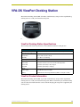
VPA-DS ViewPort Docking Station ....................................................................... 49
ViewPort Docking Station Specifications ........................................................................ 49
ViewPort Product Information ......................................................................................... 49
Battery charging ..................................................................................................................... 50
Troubleshooting ..................................................................................................... 53
ii
ViewPoint Wireless Touch Panels
Product Information
Product Information
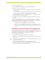
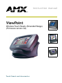
The ViewPoint Wireless Touch Panels and ViewPoint NetWave Touch Panels are hand-held liquid
crystal display panels that allow you to control devices remotely. They have programmable
firmware via the programming port.
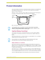
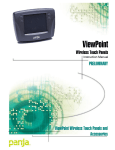
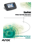
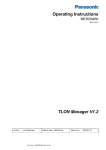
TPDesign3 is used to construct the panel pages. Buttons are used throughout the ViewPoint panel
for control over external devices. FIG. 1 shows the external jacks and buttons.
Programmable
buttons
Programming
jack
Programmable
buttons
Power jack
FIG. 1 ViewPoint Wireless Touch Panel
Panel programming, pages, and drawings are uploaded and downloaded using TPDesign
(Windows®) 16-bit or TPDesign3 (Windows) 32-bit touch panel programs. TPDesign is used to
convert G2 panel pages into G3 firmware compatible pages.
ViewPoint Wireless Touch Panel
A Color-Passive series features a six-inch LCD with 256 colors. It comes with programmable
external buttons on each side that can be used to control levels such as channels, volume, and
lighting.
The ViewPoint Touch Panels are available with either one-way RF (VPT-CP) or two-way NetWave
(VPN-CP) digital spread-spectrum wireless control.
Two-way ViewPoints do not support AMX IR codes (38 KHz and 455 KHz) but do support
other manufacturers IR codes. One-way ViewPoints support all IR codes.
Multiple ViewPoints in an installation
The ViewPoint transmits data via RF or IR. The VPT-CP ViewPoint Wireless Touch Panels are
shipped to operate on a standard frequency of 418 MHz RF and user-selectable 38 KHz or 455 KHz
IR frequencies. The ViewPoints can be ordered for different RF operating frequencies that must be
set when the unit is manufactured.
The VPN-CP operates on 2.4 GHz for two-way RF communications with the AXR-NWS NetWave
Server. It also provides one-way IR using other manufacturers IR codes. If you plan to use multiple
one-way ViewPoints within the same area, it is strongly recommended that each unit be ordered for
operation on different RF frequencies. This will prevent erroneous data being received by the
ViewPoint Wireless Touch Panels
1
Product Information
respective Controller. Refer to the AXR-NWS NetWave Server instruction manual for more
information.
The 2-way Viewpoint communication uses frequencies from 2.402 GHz to 2.478 GHz
in 1 MHz steps. This results in 76 frequencies. All 16 Group IDs utilize all 76
frequencies. Changing Group IDs basically changes the hopping pattern sequence.
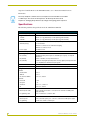
Specifications
The following table lists the specifications for the VPT-CP and VPN-CP.
Specifications
Dimensions (HWD):
5.99" x 8.75" x 2.78" (15.21 cm x 11.30 cm x 5.08 cm)
Weight:
VPT-CP
2.46 lbs. (1.11 kg) with battery, 1.97 lbs. (0.89 kg) without battery
VPN-CP
2.48 lbs. (1.12 kg) with battery, 2.01 lbs. (0.91 kg) without battery
Power:
VPA-BP (battery)
• 7.2 VDC, 6-cell NiMH (nickel metal hydride) rechargeable battery,
3.7 Ah minimum
• VPT-CP: 5 continuous hours with full back lighting
• VPN-CP: 5 continuous hours
Power supply
Power Consumption:
13.5 VDC @ 2.8 A
1.3 A @ 13.5 VDC
Operating Frequency:
RF (VPT-CP)
418 MHz standard (other frequencies available upon request), one-way RF
transmission
IR (VPT-CP)
38 KHz or 455 KHz, one-way IR transmission
RF (VPN-CP)
2.4 GHz two-way digital spread spectrum, two-way digital spread spectrum RF
or one-way OM (other manufacturer’s) IR signals
Buttons:
Four external programmable push buttons
Display:
6" (153.9 mm) color-passive LCD, 256 colors - 320 x 240 (HV) pixel
Assignable Devices:
VPT-CP
ViewPoint RF
Device 1
AMX IR
Device 1
IR other than AMX’s
Device 2, 3, and/or 4
VPN-CP
Device ID
0 - 255
Group ID
0 - 15
ViewPoint
Device 1, 2, 3, and/or 4
IR
Device 2, 3, and/or 4
Cables:
External power cable
6 mm coax male power cable - connects from an external 13.5 VDC power
supply (included)
Programming cable
3-wire, 2.5 mm stereo conductor cable
Connector Ports:
2
External power
6 mm coax female power jack - connects to external 13.5 VDC power supply
Programming
2.5 mm stereo female conductor jack
ViewPoint Wireless Touch Panels
Product Information
Specifications (Cont.)
Memory:
512 KB of SRAM and 2 MB of flash for a total of 2.5 MB
IR files
16 KB
Buttons
225 KB
Bitmaps
1245 KB
Icons
262 KB
Fonts
262 KB
Operating Temperature:
Indoor operation at temperatures between 0º C (32º F) to 40º C (104º F)
Operating Humidity:
5% to 90% RH (non-condensing)
Enclosure:
High impact molded plastic, matte black finish
Included Accessories:
VPA-BP
ViewPoint Rechargeable Battery
Power supply
13.5 VDC, PS 2.8 A power supply
Programming cable
2.5 mm stereo to male DB-9 (FG10-817)
Optional Accessories:
VPA-BP
Additional ViewPoint Rechargeable Battery (FG0962)
AXR-RF
RF Receiver (VPT-CP only) (FG782-418)
AXR-NWS
NetWave Server (VPN-CP only) (FG5930-02)
AXR-NWS/EU
NetWave Server (VPN-CP/EU only)(FG5930-12)
VPA-DS
ViewPort Docking Station (FG5961-02)
Extension cable
DB-9 extension cable (female DB-9 to female DB-9) (FG10-727)
Recharging the Battery
The battery (VPA-BP) can be recharged by connecting the 13.5 VDC power supply to the power
jack on the side of the ViewPoint (FIG. 1). The battery can also be charged on the ViewPort
docking station. Refer to the VPA-DS ViewPort Docking Station section on page 49 for more
information about charging batteries on the ViewPort docking station.
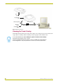
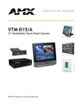
Using Connector Ports
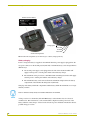
All ViewPoints have two connectors (FIG. 2). The power jack is for connecting an external
13.5 VDC power supply for ViewPoint operation and charging. The programming jack is used for
communication between the ViewPoint touch panel and TPDesign3. The programming jack uses a
three-wire, 2.5 mm stereo jack. The required cable and power supply comes furnished with the
ViewPoint.
To download and upload TPDesign3 touch panel pages:
1. Connect the 2.5 mm stereo plug (male) end of the programming cable (FG10-817) into the
programming jack on the side of the ViewPoint.
2. Connect the DB-9 end of the programming cable (FIG. 2) to the female DB-9 connector on the
DB-9 extension cable (FG10-727).
3. Connect the female DB-9 terminal end of the extension cable to the port on the back of your
computer (FIG. 2).
4. Configure the communication parameters in TPDesign3.
ViewPoint Wireless Touch Panels
3
Product Information
Power
jack
Programming
jack
Stereo plug male
ViewPoint
to PC
programming
cable
DB-9 connector
Cable FG10-817 to cable FG10-727
FIG. 2 ViewPoint connectors
Cleaning the Touch Overlay
You should clean the touch screen overlay after each day’s use. Always use clean cotton cloths, and
a spray bottle of cleaning solution consisting of 50% isopropyl alcohol and 50% water.
It is recommended that you do not attempt to replace the internal Lithium battery.
This battery has a lifespan of up to 5 years.
If there is a problem with this piece, please contact your AMX sales representative to
make arrangements to ship your panel back to the factory for battery replacement.
4
ViewPoint Wireless Touch Panels
Designing Touch Panel Pages
Designing Touch Panel Pages
The VPT-CP ViewPoint one-way models do not support bargraphs, joysticks, VGA, or video (video
bargraphs and video joysticks). These functions are available in the EDIT drop-down menus and
can be setup. However, the functions are not operational. Since the VPN-CP modules contain
two-way RF, they support both bargraphs and joysticks.
There are three ways to approach creating touch panel pages:
TPDesign3 - Refer to the TPDesign3 Touch Panel Program (Version 3.16 or higher)
instruction manual for more information.
VPXpress - Refer to the VPXpress ViewPoint System Design/Programming Software
Program (Version 1.01 or higher) instruction manual for more information.
On-board editor
This document describes the basics of using the on-board editor to create pages and buttons.
Buttons
Standard button types include rectangles and other geometric shapes that you can create with the
touch panel editor. Buttons are set with attributes, which means there is feedback for the Controller
when you touch the button.
General buttons are part of the default touch panel program and cannot be changed. You use general
buttons to create or revise pages and specify panel communication parameters. The General Button
types are described in the table below.
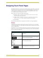
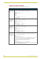
General Button Types
Selection buttons
Selection buttons appear on touch panel pages and set communication parameters.
Information buttons
Information buttons contain serial numbers and firmware version
information. The properties of these buttons cannot be changed.
These buttons have a dark fill and light text.
Adjustment buttons
You can use the UP and DN buttons to set adjustment buttons. The
adjustment button example sets the baud rate for the connection
from the touch panel to the computer.
Decision buttons
Decision buttons appear when an operation has two options and
requires verification before an action is performed.
ViewPoint Wireless Touch Panels
5
Designing Touch Panel Pages
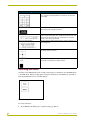
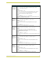
General Button Types (Cont.)
Keypad buttons
The keypad button opens a keypad so you can enter a password or
value assignment. All keypad buttons are interactive except for the
entry display.
Status buttons
Status buttons always have a dark fill with light letters and have no
functionality except to display information.
Operation bars
Operation bars appear in the place of the Editor bar, after selecting a
button or page edit operation. The operation bar indicates which edit
function is currently active. When an edit operation is selected, it
remains active until you press EXIT.
Touch to Continue buttons
"Touch to Continue" buttons appear when an operation requires user
acknowledgement.
Joystick buttons
Joysticks are vertical and horizontal direction controllers for use with
pan and tilt camera controllers.
Bargraph buttons
Bargraph buttons display a dynamic bargraph (vertical or horizontal).
An example is the Battery level indicator button.
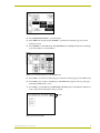
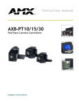
Activating Edit Mode
You must activate EDIT mode before creating touch panel pages and buttons. Use the EDIT button
to enter Edit mode. When powering up the touch panel, the first page is the Main page (see FIG. 3).
Note that the Edit button is not available initially.
FIG. 3 Main Page
To activate edit mode:
1. Press SETUP in the Main page to open the Setup page (FIG. 4).
6
VIewPoint Wireless Touch Panels
Designing Touch Panel Pages
FIG. 4 Setup page
2. Press PROTECTED SETUP to open the keypad.
3. Enter 1988 in the keypad and press ENTER to open the Protected Setup page (1988 is the
default password).
4. Press EDITOR to enable Edit mode. The EDITOR button is highlighted in the Protected Setup
page when enabled, as shown in FIG. 5.
FIG. 5 Protected Setup page with the active EDITOR button
5. Press EXIT to close the Protected Setup page and return to the Setup page (now in Edit mode).
6. Press EXIT again to return to the Main page. The EDIT button appears at the top of the page
indicating that Edit mode is active.
7. Press EDIT to open the Edit bar. The BUTTON and PAGE options, in the Edit bar, (FIG. 6) are
used to design and modify button and page settings.
Edit bar
FIG. 6 Main page with Edit bar
ViewPoint Wireless Touch Panels
7
Designing Touch Panel Pages
Setting the Device Base
Press the DEVICE BASE option, in the Protected Setup page (FIG. 5), to assign a base (starting)
device address to the touch panel.
1. Enter the base address for the touch panel. The base address range is from 1 - 255. Standard
device addresses begin at 128.
2. Press Enter to save.
Setting the Device Used
Use the DEVICE USED option in the Protected Setup page (FIG. 5) to assign a value for the
number of devices being controlled by the touch panel.
1. Press DEVICE USED to open the keypad and enter the panel’s device number from 1 - 4. Each
device number supports up to 255 programmable channel codes. The multiple device settings
allow you to create up to four unique touch panel buttons and/or pages. This value is used to
determine the current device being used by the panel.
2. Enter the number of devices being used by the touch panel.
3. Press Enter to save the value.
Adding a page
1. Press PAGE on the Edit bar to open the PAGE menu.
2. Press ADD to open the keyboard and enter a name for the new page. Page names can be up to
20 characters.
3. Press EXIT CHANGE to save, close the keyboard, and go to the new page.
Setting the page color
1. Press EDIT to open the Edit bar on the newly created page.
2. Press PAGE on the Edit bar to open the PAGE menu.
3. Press PAGE COLOR to open the color palette.
4. Select a color from the palette. The page automatically changes to the new color.
Adding a button
To add a button to the current page:
1. Press BUTTON on the Edit bar to open the BUTTON menu.
2. Press ADD to open the ADD BUTTON operation bar. Then, touch and drag on the LCD screen
to create the button. The first touch point is the upper-left corner of the button.
Resizing a button
1. Press BUTTON on the Edit bar to open the BUTTON menu.
2. Press RESIZE. Then, touch any edge of the button and drag.
3. Press EXIT on the Edit bar to exit Edit mode.
8
VIewPoint Wireless Touch Panels
Designing Touch Panel Pages
Button Properties
Use the PROPERTIES option of the BUTTON menu in the Edit bar to set button borders, page
flips, button colors for channel on and off conditions, and channel and variable text codes. These
steps apply to setting properties for external buttons as well.
1. Press BUTTON on the Edit bar to open the BUTTON menu options.
2. Press PROPERTIES to open the PROPERTIES operation bar.
3. Press the new button to open the Button Properties page.
4. Press BUTTON TYPE to open the BUTTON TYPE menu.
5. Choose a button type for the selected button to open the associated Button Properties page.
Each button type has its own Button Properties page with settings specific to the button type.
6. Press BORDER to open the BUTTON BORDER pages.
7. Select a border to set for the button and return to the Button Properties page. The BORDER
button changes to show the selected border type.
Setting the channel code
The channel button sets the device and button channel codes for the buttons. Channel codes work
the same for all button types, including joysticks and bargraphs.
1. In the Button Properties page, press DEV to open the keypad and set the touch panel’s device
number.
2. Enter 1, 2, 3, or 4 in the keypad. The programming software uses device codes 1 - 4 to identify
the touch panel. The ViewPoint has a four-device capability.
If DEVICE USED is set to 4 and Base Device Number is 128, the Controller recognizes
bus devices 128 - 131.
The panel does not allow you to enter a device number greater than the DEVICE USED
without first displaying a decision box asking if you accept the new selection or not.
For one-way ViewPoints (VPT-CP), use device number 1 for AMX IR and RF. Use
device numbers 2, 3, and 4 for other manufacturer’s IR codes (at frequencies other than
the supported 38 KHz and 455 KHz).
For two-way ViewPoints (VPN-CP), device numbers 1 - 4 can be AMX RF. The AMX IR
is not supported (38 KHz and 455 KHz); however, other manufacturer’s IR codes are
supported by assigning ViewPoint device numbers 2, 3, and 4 for IR codes.
3. Press ENTER to save the device number, close the keypad, and return to the Button Properties
page.
4. Press CHAN to open the keypad and enter a channel value of 1 - 255. The source code uses the
channel code number to identify the button and its programmed operations. The channel code
for non-active buttons is 0.
5. Press ENTER to save the channel number, close the keypad, and return to the Button
Properties page.
ViewPoint Wireless Touch Panels
9
Designing Touch Panel Pages
Setting the variable text code
The variable text buttons set the device and button channel codes for the buttons. Variable text
codes work the same for all button types, including joysticks and bargraphs.
1. Press DEV to open the keypad and set the device number.
2. Enter 1, 2, 3, or 4 in the keypad. The source code uses device codes 1 - 4 to identify the touch
panel.
3. Press ENTER to save, close the keypad, and return to the Button Properties page.
4. Press CHAN to open a keypad and set the channel number.
5. Enter a channel value of 1 - 255 in the keypad. The source code uses the channel code number
to identify the button and its operations.
6. Press ENTER to save the channel number, close the keypad, and return to the Button
Properties page.
Setting the page flip
1. Press the PAGE FLIP Type button (FIG. 7) in the Button Properties page to open the Page Flip
Type menu.
Page FLIP type
button
Flip to Page button
FIG. 7 Page FLIP Type button
2. Select a Page Flip type. If you select FLIP PREVIOUS in the Page FLIP Type menu, the FLIP
to Page button appears.
3. Press the FLIP to Page button to open a list of all the saved touch panel pages. If the desired
page is not present in the menu, verify the page has been saved.
4. Select the target page for the page flip.
Setting the button colors for channel-off conditions
1. Press any button to open the Button Properties page.
2. Press BORDER under CHANNEL OFF in the Button Properties page. The color palette
appears. Select a color to set as the border.
3. Press the FILL button in the Button Properties page to open the color palette. Select a color to
set as the fill.
4. Press the TEXT button to open the palette. Select a color to use for the text.
5. Press EXIT SAVE CHANGE in the Button Properties page to save the new button properties
and return to the current page.
10
VIewPoint Wireless Touch Panels
Designing Touch Panel Pages
Adding text, icons, and bitmaps to a button
1. Press BUTTON on the Edit bar to open the BUTTON menu.
2. Press TEXT/IMAGE to add text to the button. The TEXT/IMAGE operation bar appears.
3. Press any button to open the Text/Image page.
4. Go through each option and set as desired:
TEXT OFF and TEXT ON sets the text for the button's Off and On state.
ICON OFF and ICON ON sets the icon for the button's Off and On state.
BITMAP OFF and BITMAP ON sets the bitmap for the button's Off and On state.
MAKE ON SAME AS OFF sets the On and Off properties the same.
You cannot create or edit buttons with Unicode fonts on the panel. Any use of the
TEXT/IMAGE button to alter or create Unicode font supported buttons must be done
in the TPDesign3 Touch Panel Design Program.
5. Press EXIT SAVE CHANGE to close the Text/Image page and return to the Main page.
Using TPDesign3 to Download Bitmaps, Icons, and Fonts
TPDesign3 allows you to download bitmaps, icons, and fonts into your touch panel from an
existing touch panel program. Touch Panel programs are created in the TPDesign3 software
program. Refer to the TPDesign3 Touch Panel Program (version 3.13 or higher) instruction manual
for more information. Use the Download to Panel button to download a project file.
To download bitmaps, icons and/or fonts from an existing TPDesign3 project file:
1. Then, launch the TPDesign3 software program and open a project file that contains the desired
bitmaps, icons, and fonts.
2. Select File from the menu bar to open the File menu.
3. In the File menu, click on Download to Panel, to open the Download to Panel dialog box.
4. Click the Comm Settings tab to set the communications port, baud rate, and other
communication settings.
5. Then, click the Actions tab to set the communication mode and select which elements of the
project file you want to download to the touch panel.
6. In the What To Send area, select one or more of the available options (All Bitmaps, All Icons,
All Fonts).
7. Select the mode of communication with the touch panel (RS-232 and AXlink). Confirm that
the correct panel is selected by verifying the ID values with the Base Address assigned to the
touch panel in the Protected Setup page.
8. After clicking Connect, the Available Panels list appears in the Available Panels field. Click
Begin to start downloading the project file into the panel.
9. After completing the download, the bitmaps, icons and fonts that were downloaded are now
accessible via the BITMAPS, ICONS and FONTS menus.
ViewPoint Wireless Touch Panels
11
Designing Touch Panel Pages
Button Properties for External Pushbuttons
External pushbuttons are configured with features similar to on-screen buttons. Their functionality
can be set just as any other button on the touch panel.
Use the PROPERTIES operation bar to assign properties to external pushbuttons. The BUTTON
options and VARIABLE TEXT features within the Properties page do not appear. Although the
Border and Color sections of this page appear, they are of no use to external pushbuttons since they
do not appear on-screen.
Creating a Bargraph and Joystick
Bargraphs are level monitors and adjustable level controls. These levels can be configured to adjust
and monitor audio outputs and lighting levels. Before starting, make sure to connect the touch panel
to your Controller; otherwise, the bargraph may not work properly.
Bargraphs and Joysticks only function on VPN-CP touch panels.
Joysticks are vertical and horizontal direction controllers you can use for camera for pan and tilt
control.
Adding a bargraph or joystick button
Create a new button using the ADD operation bar in the BUTTON menu.
1. Press BUTTON in the Edit bar to open the BUTTON menu.
2. Press PROPERTIES in the BUTTON menu to open the PROPERTIES operation bar.
3. Press any button to open the Button Properties page.
4. Press BUTTON TYPE to open the BUTTON TYPE menus. Choose a button type to open its
Button Properties page.
Setting Bargraph and Joystick Properties
Use the Button Properties page to set channel, level, and button colors. Refer toSetting the variable
text code section on page 10 andSetting the channel code section on page 9 for further information.
Refer toSetting the button colors for channel-off conditions section on page 10for more information
on colors for channel-off conditions.
You are able to position the joystick crosshair in the Button Properties page.
12
VIewPoint Wireless Touch Panels
Designing Touch Panel Pages
Setting the level code
Level buttons set the device and number codes for the touch panels.
Joysticks use two level numbers. The first is for the X-axis and the second is for the
Y-axis. You only need to specify the first level.
1. Press DEV to open a keypad and set the device number.
2. Enter 1, 2, 3, or 4 in the keypad.
3. Press ENTER to save the device number, close the keypad, and return to the Button Properties
page.
4. Press NUM to open a keypad and set the level number assigned to the device.
5. Enter a number 1 – 8. Each device can range from 1 – 8 levels except for joysticks, where the
range is 1 – 7.
6. Press ENTER to save, close the keypad, and return to the Button Properties page.
ViewPoint Wireless Touch Panels
13
Designing Touch Panel Pages
14
VIewPoint Wireless Touch Panels
Programming
Programming
You can program the touch panel, using the commands in this section, to perform a wide variety of
operations using Axcess Send_Commands and variable text commands. Use the commands
described in this section to program the touch panel.
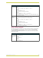
Serial Commands
Serial Commands are used in the AxcessX Terminal Emulator mode. These commands are not
insensitive.
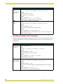
Serial Commands
?PAR
Returns panel
parameters to the
PC terminal.
Panel parameters include: firmware version, device number, mouse type, output resolution, number of devices, cursor enable, brightness, and contrast.
Syntax:
"?PAR"
Example:
?PAR
Requests the information.
$SC
Sends a serial
port
send_command
within a panel, as
if sent from
Axcess.
Syntax:
"$SC <device offset>,"’<send_command>,<variable
text #>,<data>’""
Variables:
device offset = Device number
variable text # = The variable text number value on the touch panel.
Example:
$SC 1,"’@TXT’,2,’TEXT’"
The string is sends the command to put text on a button with a variable text value of 2. It is
crucial that all the correct ’ and " be used with no spaces after the commas.
Example:
$SC 1,"’SLEEP’"
Sets a touch panel to sleep.
CALIBRATE
Starts touch panel
calibration.
Syntax:
"CALIBRATE"
Example:
CALIBRATE
Starts the calibration sequence mode on the touch panel.
CHECK CAL
Enters the calibration test mode.
Syntax:
"CHECK CAL"
Example:
CHECK CAL
Begins the calibration check mode on the touch panel.
ECHO ON
Turns On character echo.
Syntax:
"ECHO ON"
Example:
ECHO ON
The character echo is sent back to the computer.
ViewPoint Wireless Touch Panels
15
Programming
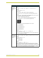
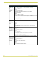
Serial Commands (Cont.)
ECHO OFF
Syntax:
Turns Off character echo.
Example:
"ECHO OFF"
ECHO OFF
The character echo is not sent back to the computer.
GET CAL
Gets the calibration variables.
Syntax:
"GET CAL"
Example:
GET CAL
Gets the calibration variables on the touch panel.
HELLO
Syntax:
Verifies that serial
communication is
working properly.
Example:
"HELLO"
HELLO
If the communication is active and working, the response is "How are you doing?".
LZAP!
Syntax:
Clears all lowlevel memory and
erases external
touch drivers.
Example:
"LZAP!"
LZAP!
Clears all IR codes from the panel. Commands such as LZAP! and ZAP! can be used as
both Serial Commands or Send_Commands.
RESET
Cycles power on
the touch panel.
Syntax:
"RESET"
Example:
RESET
Cycles the power on the touch panel. Once the firmware is downloaded, send this command to recycle power to the panel. This command prevents the user from having to physically re-cycling power on the unit.
SET CAL
Sets the calibration variables.
Syntax:
“SET CAL <X Multiplier> <X Offset> <Y Multiplier> <Y
Offset>"
Example:
SET CAL 2F 3A 2B 62
Sets the calibration values on the touch panel.
SETUP
Puts the touch
panel on the
Setup Page.
Syntax:
"SETUP"
Example:
SETUP
Flips the touch panel to the Setup page.
VER
Restores the current version.
Syntax:
"VER"
Example:
VER
Returns the current version of the main firmware.
16
ViewPoint Wireless Touch Panels
Programming
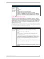
Serial Commands (Cont.)
WORKING?
Syntax:
Verifies the com"WORKING?"
munication
Example:
between the touch
WORKING?
panel and the Terminal Emulator.
Response:
$SC 1,"’CPAGE72-Main Page’"
Responding touch panel turns its Main page the color white. This command verifies serial
communication. The ViePoint panel must have a page named Main Page for this command to work properly.
ZAP!
Clears all memory and erases
buttons, pages,
drawings, and
symbols.
Syntax:
"ZAP!"
Example:
"ZAP!"
Clears all memory and erases all buttons, pages, drawings, and symbols.
Only use the ZAP! command to erase the saved data in the touch panel; data cannot be
recovered after it is erased.
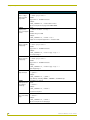
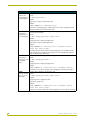
System Send_Commands
System Send_Commands are stored in the Controller and direct the touch panel to perform various
operations.
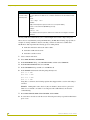
System Send_Commands
$SP
Translates the ¦ and translates it as a carriage return to the next line.
Sends data out
Syntax:
the serial port with
"’$SP "<data>"’"
trailing CR and LF.
Example:
SEND_COMMAND TP,"’$SP "CALIBRATE"’"
Sends the Calibrate command to another panel through the Serial Port. It is crucial that all
the correct ’ and " be used with no spaces after the commas.
ABEEP
Syntax:
Outputs one panel
"’ABEEP’"
beep even if the
Example:
beep value is set
SEND_COMMAND TP,"’ABEEP’"
to 0 in the Setup
page.
Beeps the panel.
ADBEEP
Syntax:
Outputs a double
"’ADBEEP’"
beep even if the
Example:
double beep value
SEND_COMMAND TP,"’ADBEEP’"
is set to 0 in the
Setup page.
Double beeps the panel.
ViewPoint Wireless Touch Panels
17
Programming
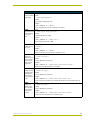
System Send_Commands (Cont.)
AKEYB
The keyboard string is set to null during power-up and stored until power-down.
Opens the touch
panel keyboard
and initializes the
text string entry.
Syntax:
“’AKEYB-<text string>’"
Variable:
text string = 0 - 59 characters
Example:
SEND_COMMAND TP,"’AKEYB-TOUCH HERE’"
Opens the touch panel keyboard with TOUCH HERE in the display.
AKEYP
The keyboard string is set to null during power-up and stored until power-down.
Opens the touch
panel keypad and
initializes the
number string
entry.
Syntax:
"’AKEYP-<number string>’"
Variable:
number string = 0 - 9999
Example:
SEND_COMMAND TP,"’AKEYP-1988’"
Opens the touch panel keypad with 1988 in the display.
AKEYR
Syntax:
Closes/opens the
touch panel keyboard/pad.
Example:
"’AKEYR’"
SEND_COMMAND TP,"’AKEYR’"
Closes the keyboard/keypad opened using the ’AKEYB’, ’AKEYP’, or ’PKEYP’
commands.
BAUD
The baud rate can also be set in the Protected Setup page’s BAUD level indicator.
Sets the program
port baud rate.
Syntax:
"’BAUD <baud rate>’"
Variable:
baud rate = 38400, 19200, 9600, 4800, 2400, 1200, 600, and 300
Example:
SEND_COMMAND TP,"’BAUD 38400’"
Sets the Baud rate to 38400.
BEEP
This beep command sounds one tone for a time length of 50 milliseconds.
Gives an output of Syntax:
one beep.
"’BEEP’"
Example:
SEND_COMMAND TP,"’BEEP’"
Activates one beep tone. Beeps the panel if the Beep button is not set to 0. The BEEP
command does disable the beep after a QBEEP command.
BRIT
Syntax:
Adjusts brightness
"’BRIT-<level>’"
of display.
Variable:
level = 1 - 5 (1 = minimum; 5 = maximum)
Example:
SEND_COMMAND TP,"’BRIT-5’"
Sets to highest brightness level.
18
ViewPoint Wireless Touch Panels
Programming
System Send_Commands (Cont.)
CALIBRATE
Syntax:
Starts the touch
panel calibration
sequence.
Example:
"’CALIBRATE’"
SEND_COMMAND TP,"’CALIBRATE’"
Starts the calibration operation on the touch panel.
CONT
Adjusts contrast of
display.
Syntax:
"’CONT-<level>’"
Variable:
level = 1 - 12 (1 = minimum; 12 = maximum)
Example:
SEND_COMMAND TP,"’CONT-12’"
Sets display to highest contrast level.
CLOCK
Sets the time and
date.
Syntax:
"’CLOCK <mm-dd-yy> <hh:mm:ss>’"
Variables:
mm = 01 - 12, dd = 01 - 31, yy = 00 - 99
hh = 00 - 23, mm = 00 - 59, ss = 00 - 59
Example:
SEND_COMMAND TP,"’CLOCK 02-08-98 19:16:00’"
Sets the touch panel’s date to February 8, 1998, and time to 7:16 p.m.
DBEEP
Gives a double
beep output.
This command only works if the Double Beep value in the Protected Setup page is set to
On.
Syntax:
"’DBEEP’"
Example:
SEND_COMMAND TP,"’DBEEP’"
Double beeps the panel.
ILEV
Inverts the joystick
axis.
Syntax:
"’ILEV <joystick axis to invert>’"
Variables:
joystick axis to invert =
0 = Normal G3 joystick (origin: top left)
1 = Invert horizontal axis (origin: top right)
2 = Invert vertical axis (origin: bottom left)
3 = Invert both axes (origin: bottom right)
Example:
SEND_COMMAND TP,"’ILEV 3’"
Inverts the joystick axis to move the origin to another corner.
LZAP!
This command can be used as Serial Commands and Send_Commands.
Clears all lowlevel memory and
erases IR codes.
Syntax:
"’LZAP’"
Example:
SEND_COMMAND TP,"’LZAP!’"
Clears all IR codes from the panel.
ViewPoint Wireless Touch Panels
19
Programming
System Send_Commands (Cont.)
PAGE
Syntax:
Flips to a page
with a specified
page name.
Variable:
"’PAGE-<page name>’"
page name = 1 - 50 ASCII characters
Example:
SEND_COMMAND TP,"’PAGE-MAIN PAGE’"
Flips the touch panel to the page named MAIN PAGE.
PKEYP
Syntax:
Displays asterisks (*) for keypad
entries.
Variable:
"’PKEYP-<number string>’"
number string = 0 - 9999
Example:
SEND_COMMAND TP,"’PKEYP-1988’"
Displays the touch panel keypad with **** instead of 1988.
PPOF
Closes a specific
popup page.
Syntax:
"’PPOF-<page name>’"
Variable:
page name = 1 - 50 ASCII characters
Example:
SEND_COMMAND TP,"’PPOF-Popup Page 1’"
Closes Popup Page 1.
PPON
Opens a specific
popup page.
Syntax:
"’PPON-<page name>’"
Variable:
page name = 1 - 50 ASCII characters
Example:
SEND_COMMAND TP,"’PPON-Popup Page 1’"
Opens Popup Page 1.
QBEEP
Stops all beeps.
Syntax:
"’QBEEP’"
Example:
SEND_COMMAND TP,"’QBEEP’"
Stops all beeps, including "’ABEEP’", "’ADBEEP’", and AXlink beeps.
RESET
Saved data is not cleared.
Clears panel status (same as
power up).
Syntax:
"’RESET’"
Example:
SEND_COMMAND TP,"’RESET’"
Resets the touch panel.
SETUP
Goes to the Setup
page.
Syntax:
"’SETUP’"
Example:
SEND_COMMAND TP,"’SETUP’"
Flips the touch panel to the Setup page.
20
ViewPoint Wireless Touch Panels
Programming
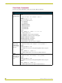
System Send_Commands (Cont.)
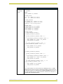
TPAGEON
Syntax:
Activates page
tracking.
Example:
"’TPAGEON’"
SEND_COMMAND TP,’TPAGEON’
DEFINE_DEVICE
TP1 = 128 (*AMX Touch Panel*)
TP2 = 129 (*AMX Touch Panel*)
DEFINE_VARIABLE
TP1_BUFFER[100] (*Buffer for TP1*)
TP2_BUFFER[100] (*Buffer for TP2*)
TRASH[50] (*For Parsing Above*)
DEFINE_START
CREATE_BUFFER TP1,TP1_BUFFER
CREATE_BUFFER TP2,TP2_BUFFER
SEND_COMMAND TP1,'TPAGEON'
SEND_COMMAND TP2,'TPAGEON'
DEFINE_PROGRAM
(* PAGE TRACKING ROUTINE *)
IF(LENGTH_STRING(TP1_BUFFER))
{
IF(FIND_STRING(TP1_BUFFER,'PAGE-',1))
{
TRASH=REMOVE_STRING(TP1_BUFFER,'PAGE-',1)
SEND_COMMAND TP2,"'PAGE-',TP1_BUFFER"
CLEAR_BUFFER TP1_BUFFER
}
IF((FIND_STRING(TP1_BUFFER,'PPON-',1))
OR(FIND_STRING(TP1_BUFFER, 'PPOF-',1)))
{
SEND_COMMAND TP2,TP1_BUFFER
CLEAR_BUFFER TP1_BUFFER
}
}
IF(LENGTH_STRING(TP2_BUFFER))
{
IF(FIND_STRING(TP2_BUFFER,'PAGE-',1))
{
TRASH=REMOVE_STRING(TP2_BUFFER,'PAGE-',1)
SEND_COMMAND TP1,"'PAGE-',TP2_BUFFER"
CLEAR_BUFFER TP2_BUFFER
}
IF((FIND_STRING(TP1_BUFFER,'PPON-',1)) OR
(FIND_STRING(TP1_BUFFER,'PPOF-',1)))
{
SEND_COMMAND TP1,TP2_BUFFER
CLEAR_BUFFER TP2_BUFFER
}
}
(* The command string is sent to the Controller in the ’PAGE-(page name)’ or ’PPON/
PPOF-(page name)’ format. The string is captured in the buffer for one panel and sent to
the other panel. If panels are combined using the DEFINE_COMBINE statement, the routine needs to be written only once, and the command is sent back to the same panel. *)
(* END OF PAGE TRACKING ROUTINE *)
ViewPoint Wireless Touch Panels
21
Programming
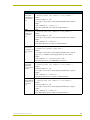
System Send_Commands (Cont.)
SLEEP
Syntax:
Forces the touch
panel to screen
saver mode.
Example:
"’SLEEP’"
SEND_COMMAND TP,"’SLEEP’"
Activates the screen saver mode.
TPAGEOFF
Deactivates page
tracking.
Syntax:
"’TPAGEOFF’"
Example:
SEND_COMMAND TP,"’TPAGEOFF’"
Deactivates the page tracking option.
WAKE
Syntax:
Deactivates
screen-saver
mode and resets
the sleep timer.
Example:
"’WAKE’"
SEND_COMMAND TP,"’WAKE’"
Deactivates the touch panel screen-saver mode and resets the sleep timer.
XMRT
Sets the new network communication retry value for
the panel and
SoftROM.
Syntax:
"’XMRT <number>’"
Variable:
number = 1 - 15 ASCII characters
Example:
SEND_COMMAND TP,"’XMRT 9’"
Sets the XMODEM wait for character retries to 9.
XMTO
Sets the new network communication delay for the
panel and SoftROM.
Syntax:
"’XMTO <number>’"
Variable:
number = 4 - 30 ASCII characters
Example:
SEND_COMMAND TP,"’XMTO 5’"
Sets the new XMODEM character delay time to 5 seconds.
ZAP!
Clears all memory; erases buttons, pages,
drawings, and
symbols.
Syntax:
"’ZAP!’"
Example:
SEND_COMMAND TP,"’ZAP!’"
Clears all memory and erases all buttons, pages, drawings, and symbols.
Only use the ZAP! command to erase the saved data in the touch panel; data cannot be
recovered after it is erased.
22
ViewPoint Wireless Touch Panels
Programming
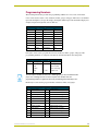
Programming Numbers
The following information provides the programming numbers for colors, fonts, and borders.
Colors can be used to set the colors on buttons, sliders, gauges, and pages. The lowest color number
represents the lightest color-specific display; the highest number represents the darkest display. For
example, 0 represents light red, and 5 is dark red.
Colors and Programming Numbers
Color
No.
Color
No.
Red
0-5
Purple
54 - 59
Orange
6 - 11
Magenta
60 - 65
Yellow
12 - 17
Pink
66 - 71
Lime
18 - 23
White
72 - 77
Green
24 - 29
Grey
78 - 83
Aqua
30 - 35
More Grey
84 - 86
Cyan
36 - 41
Black
87
Royal
42 - 47
Transparent
255
Font styles can be used to program the text fonts on buttons, sliders, gauges, and pages. The
programming numbers are assigned consecutively when downloaded to the touch panel.
Font Styles and Programming Numbers
No.
Font styles
No.
Font styles
1
Extra small
5
Extra large
2
Small
6
Hollow medium
3
Medium
8
Hollow extra large
4
Large
32 - 255
Variable fonts
You must import variable text fonts into a TPDesign3 project file, and download the
project file containing the fonts to the touch panel. The variable fonts are
programming numbers assigned by the touch panel during the download process.
Border styles can be used to program borders on buttons, sliders, and gauges.
Border Styles and Programming Numbers
No.
Border styles
No.
Border styles
0
No border
11
Double shadow
1
No border special
20
3-dimensional rectangle 1
2
Single line
21
3-dimensional rectangle 2
3
Double line
22
3-dimensional round 1
4
Triple line
23
3-dimensional round 2
5
Single rounded
24
3-dimensional neon 1
6
Double rounded
25
3-dimensional neon 2
7
Single raised
26
3-dimensional neon blue
8
Double raised
27
3-dimensional neon green
9
Triple raised
40
Single diamond
10
Double-line two single
41
Double diamond
ViewPoint Wireless Touch Panels
23
Programming
Shorthand Send Commands
The shorthand commands operate control equipment just like standard Send_Commands still used
in a wide variety of AMX products. However, shorthand commands are smaller byte-for-byte, and
are processed more efficiently. The table below lists the shorthand Send_Commands you can use
with the ViewPoint touch panels. The shorthand command data is 1-byte, non-ASCII format except
for pages, passwords, text, and bitmap names.
Shorthand Send_Commands
@CBF
This works only if the specified background color is not the same as the current color.
Sets the OFF
feedback border
color to the specified color.
Syntax:
"’@CBF’,<variable text address>,<color_number>"
Variables:
variable text address = 1 - 255
color number = See the Colors and Programming Numbers table on page 23.
Example:
SEND_COMMAND TP,"’@CBF’,1,0"
Sets the OFF feedback border color to Red for the variable text button 1.
@CBN
This works only if the specified background color is not the same as the current color.
Sets the ON feed- Syntax:
back border color
"’@CBN’,<variable text address>,<color_number>"
to the specified
Variables:
color.
variable text address = 1 - 255
color number = See the Colors and Programming Numbers table on page 23.
Example:
SEND_COMMAND TP,"’@CBN’,2,78"
Sets the ON feedback border color to Grey for variable text button 2.
@CFF
This only works if the specified background color is not the same as the current color.
Sets the OFF
feedback fill color
to the specified
color.
Syntax:
"’@CFF’,<variable text address>,<color_number>"
Variables:
variable text address = 1 - 255
color number = See the Colors and Programming Numbers table on page 23.
Example:
SEND_COMMAND TP,"’@CFF’,1,72"
Sets the OFF feedback fill color to White for variable text button 1.
@CFN
This only works if the specified background color is not the same as the current color.
Sets the ON feed- Syntax:
back fill color to
"’@CFN’,<variable text address>,<color_number>"
the specified
Variables:
color.
variable text address = 1 - 255
color number = See the Colors and Programming Numbers table on page 23.
Example:
SEND_COMMAND TP,"’@CFN’,1,30"
Sets the ON feedback fill color to Aqua for variable text button 1.
24
ViewPoint Wireless Touch Panels
Programming
Shorthand Send_Commands (Cont.)
@CPG
This only works if the new background color is not the same as the current color.
Sets the page with Syntax:
specified page
"’@CPG’,<color_number>,’<page name>’"
name backVariables:
ground color to
color number = See the Colors and Programming Numbers table on page 23.
the specified
color.
page name = 1 – 50 ASCII characters
Example:
SEND_COMMAND TP,"’@CPG’,87,’Main Page’"
Sets the page title to Main Page, and the color to Black.
@CPP
This only works if the specified background color is not the same as the current color.
Sets the specified
page’s background color to
the specified
color.
Syntax:
"’@CPP’,<color_number>,’<pop-up page name>’"
Variables:
color number = See the Colors and Programming Numbers table on page 23.
pop-up page name = 1 – 50 ASCII characters
Example:
SEND_COMMAND TP,"’@CPP’,54,’Audio Page’"
Sets the popup page title to Audio Page, and the color to Purple.
@CTF
This only works if the specified background color is not the same as the current color.
Sets the OFF
feedback text
color to the specified color.
Syntax:
"’@CTF’,<variable text address>,<color_number>"
Variables:
variable text address = 1 – 255
color number = See the Colors and Programming Numbers table on page 23.
Example:
SEND_COMMAND TP,"’@CTF’,1,87"
Sets the OFF feedback text color to Black for variable text button 1.
@CTN
This only works if the specified background color is not the same as the current color.
Sets the ON feed- Syntax:
back text color to
"’@CTN’,<variable text address>,<color_number>"
the specified
Variables:
color.
variable text address = 1 – 255
color number = See the Colors and Programming Numbers table on page 23.
Example:
SEND_COMMAND TP,"’@CTN’,1,72"
Sets the ON feedback text color to White for variable text button 1.
@IDF
Syntax:
The touch panel
returns its
MS-DOS file
name in a string.
Example:
"’@IDF’"
SEND_COMMAND TP,"’@IDF’"
The touch panel returns its MS-DOS file name in a string.
@IDP
Queries the touch
panel to return a
string with the
TPDesign3
project name.
ViewPoint Wireless Touch Panels
Syntax:
"’@IDP’"
Example:
SEND_COMMAND TP,"’@IDP’"
The touch panel returns a string containing the TPDesign3 project name.
25
Programming
Shorthand Send_Commands (Cont.)
@PPA
If no page is specified, the active page is used.
Removes all
Syntax:
popup pages from
"’@PPA-<page name>’"
a specified page.
Variable:
page name = target touch panel page name
Example:
SEND_COMMAND TP,"’@PPA-Main Page’"
If there were several popup pages on ’Main Page’ that are active, sending the previous
command would remove them all from that page.
@PPF
Deactivates a
popup page on a
touch panel page.
If a page name is empty, the current page is used. If a pop-up page is part of a group, the
whole group is deactivated.
Syntax:
"’@PPF-<popup page name>;<page name>’"
Variables:
popup page name = target popup page name
page name = target touch panel page name
Example:
SEND_COMMAND TP,"’PPF-Laser Disc 2 Transport Control;
Laser Disc Control Page’"
Deactivates the Laser Disc 2 Transport Control popup page on the Laser Disc Control
Page. If a page name is empty, the current page is used. If the popup page is part of a
group, the whole group is deactivated.
@PPK
If a pop-up page is part of a group, the whole group is deactivated.
Deactivates a
popup page on all
touch panel
pages.
Syntax:
"’@PPK-<popup page name>’"
Variable:
popup page name = target popup page name
Example:
SEND_COMMAND TP,"’@PPK-Laser Disc 2 Transport Control’"
Deactivates the Laser Disc 2 Transport Control popup page on all touch panel pages.
@PPN
If a page name is empty, the current page is used.
Activates a popup
page on a touch
panel page.
Syntax:
"’@PPN-<popup page name>;<page name>’"
Variables:
popup page name = popup page name
page name = page name
Example:
SEND_COMMAND TP,"’@PPN-Laser Disc 2 Transport Control;
Laser Disc Control Page’"
Activates the Laser Disc 2 Transport Control popup page on the Laser Disc Control Page.
26
ViewPoint Wireless Touch Panels
Programming
Shorthand Send_Commands (Cont.)
@PPX
The group that needs to be turned Off must contain the given popup page.
Removes all panel Syntax:
popup pages.
"’@PPX-<popup page>’"
Variable:
popup page = popup page name
Example:
SEND_COMMAND TP,"’@PPX’"
Closes all popup pages from all of the pages in the panel.
@PWD
Syntax:
Sets the password
"’@PWD-<page flip password>’"
for the Page Flip
Variable:
on the touch
page flip password = 0 - 9999
panel.
Example:
SEND_COMMAND TP,"’@PWD-1988’"
Sets the page flip password to 1988.
@RDW
Redraws the current screen.
Syntax:
"’@RDW’"
Example:
SEND_COMMAND TP,"’@RDW’"
Sends a message to the touch panel to redraw the screen.
@SSL
Changes the
Sleep string sent
to the Controller
when the touch
panel activates
sleep mode.
Syntax:
"’@SSL-<string>’"
Variable:
string = alphanumeric characters
Example:
SEND_COMMAND TP,"’@SSL-Touch Panel Deactivated’"
Sends Touch Panel Deactivated to the Controller.
@SST
Syntax:
Changes the Star"’@SST-<string>’"
tup string sent to
Variable:
the Central Constring = alphanumeric characters
troller when the
touch panel pow- Example:
ers up.
SEND_COMMAND TP,"’@SST-Touch Panel Power On’"
Sends touch panel Power On to the Central Controller when the touch panel powers up.
@SWK
Changes the
Wakeup string
sent to the Controller when the
touch panel is
activated.
Syntax:
"’@SWK-<string>’"
Variable:
string = alphanumeric characters
Example:
SEND_COMMAND TP,"’@SWK-Touch Panel Activated’"
Sends Touch Panel Activated to the Central Controller.
ViewPoint Wireless Touch Panels
27
Programming
Color Send_Commands
Use the color Send_Commands to set the colors for text, buttons, and pages.
Color Send_Commands
CALL
See the Colors and Programming Numbers table on page 23 for more information.
Sets the colors for Syntax:
a variable text but- "’CALL<variable text address>-<data>’"
ton.
Variables:
variable text address = 1 - 255
data = 6 color number series for:
FILL COLOR ON
FILL COLOR OFF
BORDER COLOR ON
BORDER COLOR OFF
TEXT COLOR ON
TEXT COLOR OFF
Example:
SEND_COMMAND TP,"’CALL1-1 3 0 0 72 74’"
Sets variable text button 1 to:
FILL COLOR ON = Red one shade from brightest
FILL COLOR OFF = Red three shades from brightest
BORDER COLOR ON = Red brightest
BORDER COLOR OFF = Red brightest
TEXT COLOR ON = White brightest
TEXT COLOR OFF = White two shades from brightest
CBOFF
Sets the OFF
feedback border
color to the specified color.
Syntax:
"’CBOFF<variable text address>-<color_number>’"
Variables:
variable text address = 1 - 255
color number = See the Colors and Programming Numbers table on page 23.
Example:
SEND_COMMAND TP,"’CBOFF1-0’"
Sets the OFF feedback border color to Red for the variable text button 1.
CBON
Syntax:
Sets the ON feed"’CBON<variable text address>-<color_number>’"
back border color
Variables:
to the specified
variable text address = 1 - 255
color.
color number = See the Colors and Programming Numbers table on page 23.
Example:
SEND_COMMAND TP,"’CBON1-48’"
Sets the ON feedback border color to Aqua for variable text button 1.
28
ViewPoint Wireless Touch Panels
Programming
Color Send_Commands (Cont.)
CFOFF
Syntax:
Sets the OFF
feedback fill color
to the specified
color.
Variables:
"’CFOFF<variable text address>-<color_number>’"
variable text address = 1 - 255
color number = See the Colors and Programming Numbers table on page 23.
Example:
SEND_COMMAND TP,"’CFOFF1-72’"
Sets the OFF feedback fill color to White for variable text button 1.
CFON
Syntax:
Sets the ON feed"’CFON<variable text address>-<color_number>’"
back fill color to
Variables:
the specified
variable text address = 1 - 255
color.
color number = See the Colors and Programming Numbers table on page 23.
Example:
SEND_COMMAND TP,"’CFON1-48’"
Sets the ON feedback fill color to Blue for variable text button 1.
CPAGE
Syntax:
Sets the back"’CPAGE<color_number>-<page name>’"
ground page color Variables:
to the specified
color number = See the Colors and Programming Numbers table on page 23.
color.
page name = 1 - 50 ASCII characters (page names are case sensitive.)
Example:
SEND_COMMAND TP,"’CPAGE255-MAIN PAGE’"
Sets the background color on the MAIN PAGE to Transparent.
CTOFF
Sets the OFF
feedback text
color to the specified color.
Syntax:
"’CTOFF<variable text address>-<color_number>’"
Variables:
variable text address = 1 - 255
color number = See the Colors and Programming Numbers table on page 23.
Example:
SEND_COMMAND TP,"’CTOFF1-87’"
Sets the OFF feedback text color to Black for variable text button 1.
CTON
Syntax:
Sets the ON feed"’CTON<variable text address>-<color_number>’"
back text color to
Variables:
the specified
variable text address = 1 - 255
color.
color number = See the Colors and Programming Numbers table on page 23.
Example:
SEND_COMMAND TP,"’CTON1-72’"
Sets the ON feedback text color to White for variable text button 1.
ViewPoint Wireless Touch Panels
29
Programming
Variable Text Send_Commands
Use variable text Send_Commands to set the borders, fonts, and text.
Variable Text Send_Commands
!B
Sets a specific
button to On or
Off.
Syntax:
"’!B’,<variable text address>,<ON/OFF>"
Variables:
variable text address = 1 - 255
ON = 0
OFF = 1
Example:
SEND_COMMAND TP,"’!B’,128,1"
Sets button 128 Off.
BTOF
Sets a specific
button's active
state to Off.
Syntax:
"’BTOF<variable text address>’"
Variable:
variable text address = 1 - 255
Example:
SEND_COMMAND TP,"’BTOF255’"
Sets the state for button 255 to Off.
BTON
Syntax:
Sets a specific
button's active
state to On.
Variable:
"’BTON<variable text address>’"
variable text address = 1 - 255
Example:
SEND_COMMAND TP,"’BTON128’"
Sets the state for button 128 to On.
!C
Sets the border,
font, and text in
one command.
Syntax:
"’!C’,<variable text address>,<border style>,<font
size>,’<new button text>’"
Variables:
variable text address = 1 - 255
border style = See the Border Styles and Programming Numbers table on page 23.
font size = See the Font Styles and Programming Numbers table on page 23.
new button text = Enter button text to appear on the button.
Example:
SEND_COMMAND TP,"’!C’,1,6,6,’VCR PLAY’"
Sets the title on variable text button one to VCR PLAY using a hollow medium font, and
changes the border attribute to double rounded.
30
ViewPoint Wireless Touch Panels
Programming
Variable Send_Commands (Cont.)
!C
Sets the border,
font, and text in
one command.
Syntax:
"’!C’,<variable text address>,<border style>,<font
size>,’<new button text>’"
Variables:
variable text address = 1 - 255
border style = See the Border Styles and Programming Numbers table on page 23.
font size = See the Font Styles and Programming Numbers table on page 23.
new button text = Enter button text to appear on the button.
Example:
SEND_COMMAND TP,"’!C’,1,6,6,’VCR PLAY’"
Sets the title on variable text button one to VCR PLAY using a hollow medium font, and
changes the border attribute to double rounded.
!F
Syntax:
Shorthand
version of ’FONT’
command.
Variables:
"’!F’,<variable text address>,’<font size>’"
variable text address = 1 - 255
font size = See the Font Styles and Programming Numbers table on page 23.
Example:
SEND_COMMAND TP,"’!F’,’1,’6’"
Changes the font on the variable text button one to hollow medium.
FONT
Changes the font
size (or style) of
the text in a
specific button.
Syntax:
"’FONT<variable text address>-<font size/style>’"
Variables:
variable text address = The number of the variable text button (1-255).
font size/style = The size or style of the font (1-255). See the Font Styles and
Programming Numbers table on page 23.
Example:
SEND_COMMAND TP,"’FONT1-6’"
Changes the font on the variable text button one to hollow medium. Variable fonts start at
a value of 32.
!I
Syntax:
Shorthand
version of ’ICON’
command.
Variables:
"’!I’,<variable text address>,’<border style>’"
variable text address = 1 - 255
border style = 0 - 41. See the Border Styles and Programming Numbers table on
page 23.
Example:
SEND_COMMAND TP,"’!I’,1,’6’"
Changes the border style on the variable text button one to double rounded.
ICON
Changes the
border style of a
specific button.
Syntax:
"’ICON<variable text address>-<border style>’"
Variables:
variable text address = 1 - 255
border style = See the Border Styles and Programming Numbers table on page 23.
Example:
SEND_COMMAND TP,"’ICON25-6’"
Changes the border style on the variable text button 25 to double-rounded.
ViewPoint Wireless Touch Panels
31
Programming
Variable Send_Commands (Cont.)
!T
Syntax:
Shorthand
version of 'TEXT'
command.
Variables:
"’!T’,<variable text address>,’<new button text>’"
variable text address = 1 - 255
new button text = 1 - 60 characters
Example:
SEND_COMMAND TP,"’!T’,1,’VCR PLAY’"
Changes the title on variable text button one to VCR PLAY.
TEXT
Use the | character to display text on multiple lines.
Enters text on a
button.
Syntax:
"’TEXT<variable text address>-<new button text>’"
Variables:
variable text address = 1 - 255
new button text = Enter button text to appear on button.
Example:
SEND_COMMAND TP,"’TEXT2-VCR|PLAY’"
Sets the VCR and PLAY text on variable button 2. The | character places VCR on a text
line above PLAY on the button.
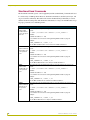
Shorthand Variable Text Commands
The table below lists the shorthand variable text commands you can use with the touch panel. The
shorthand command data is one-byte, non-ASCII format except for pages, passwords, text, and
bitmap names.
Shorthand Variable Text Commands
@BMP
Adds a bitmap file
to a button.
Bitmap files are imported into TPDesign3; the numbers are assigned by the touch panel
during the download process.
Syntax:
"’@BMP’,<variable text address>,’<bitmap>’"
Variables:
variable text address = 1 - 255
bitmap = Bitmap chosen from a file location.
Example:
SEND_COMMAND TP,"’@BMP’,85,’Bitmap1’"
Adds the Bitmap1 file to button 85.
@BOR
Sets the border
style on a button.
Syntax:
"’@BOR’,<variable text address>,<border style>"
Variables:
variable text address = 1 - 255
border style = See the Border Styles and Programming Numbers table on page 23.
Example:
SEND_COMMAND TP,"’@BOR’,65,11"
Sets the border style to double shadow on button 65.
32
ViewPoint Wireless Touch Panels
Programming
Shorthand Variable Text Commands (Cont.)
@BMF
This command allows you to program up to 12 attributes on one command line.
Sets multiple
Syntax:
attributes to a but"’@BMF’,<variable text address>,’<attribute data>’"
ton, slider, or
Variables:
gauge.
variable text address = 1 - 255
attribute data:
’%R,<left>, <top>, <right>, <bottom>’ = Sets the rectangle position.
’%B’,<border styles> = See the Border Styles and Programming Numbers table on
page 23.
’%F’,<font styles> = See the Font Styles and Programming Numbers table on page 23.
’%T’,<button text > = ASCII characters (empty is clear)
’%P’,<bitmap> = Bitmap filename (empty is clear)
’%I’,<icon> = 1 - 255 (icon numbers are assigned in TPDesign3 project file)
’%J’,<text alignment> = 1 - 9 as shown the following alignment chart:
1
2
3
4
5
6
7
8
9
For %C1-%C6, Colors and Programming Numbers table on page 23.
’%C1’,<on-state fill color>
’%C2',<off-state fill color>
’%C3’,<on-state border color>
’%C4’,<off-state border color>
’%C5’,<on-state text color>
’%C6’,<off-state text color>
Example:
SEND_COMMAND TP,"’@BMF’,255,’%T POWER |ON’
’%B’,’4’,’%C1’,’72’"
Sets the text on button 255 to POWER ON (appears on two lines), adds a triple-line border, and sets the On-state color to White.
@ENA
Enables/disables
buttons based on
the variable text
channel.
Syntax:
"’@ENA’,<variable text address>,<disable button on/off>"
Variables:
variable text address = 1 – 255
disable button on/off=
1 : button disabled
0 : button enabled
Example:
SEND_COMMAND TP,"’@ENA’,128,1"
Disables the button with variable text channel 128. This button will stop responding to
pushes completely, until it is sent an Enable command. Nothing short of a touch panel
SoftROM firmware reload will re-enable the button. Reloading the touch panel file, reloading the Axcess program, or resetting power on the panel or master will not re-enable the
button. It must be sent an Enable command once it has been disabled.
ViewPoint Wireless Touch Panels
33
Programming
Shorthand Variable Text Commands (Cont.)
@FON
Syntax:
Sets the text font
on a button.
Variables:
"’@FON’,<variable text address>,<font style>"
variable text address = 1 - 255
font style = See the Font Styles and Programming Numbers table on page 23.
Example:
SEND_COMMAND TP,"’@FON’,56,32"
Sets the text on button 56 to variable font style 32.
@ICO
Assigns an icon to
a button.
Syntax:
"’@ICO’,<variable text address>,<icon file number>"
Variables:
variable text address = 1 - 255
icon file number = 1 - 255
Example:
SEND_COMMAND TP,"’@ICO’,16,12"
Adds icon 12 on button 16. Setting the icon value to 0 clears the appearance of the icon.
@JUS
Syntax:
Sets the text
alignment on a
button.
Variables:
"’@JUS’,<variable text address>,<text alignment>"
variable text address = 1 - 255
text alignment = 1 - 9 as shown in the following alignment chart:
1
2
3
4
5
6
7
8
9
Example:
SEND_COMMAND TP,"’@JUS’,9,5"
Centers the text on button 9.
@SHO
Sets a specific
button to on or off.
Syntax:
"’@SHO’,<variable text address>,<button on/off>"
Variables:
variable text address = 1 - 255
button on/off=
0 : button Off
1 : button On
Example:
SEND_COMMAND TP,"’@SHO’,128,0"
Sets button 128 off.
34
ViewPoint Wireless Touch Panels
Programming
Shorthand Variable Text Commands (Cont.)
@TXT
Use the | character to display text on multiple lines.
Adds text to a but- Syntax:
ton.
"’@TXT’,<variable text address>,’<text>’"
Variables:
variable text address = 1 - 255
text = Enter button text to appear on the button.
Example:
SEND_COMMAND TP,"’@TXT’,2,’VCR|PLAY’"
Sets the VCR and PLAY text on variable button 2. The | character places VCR on a text
line above PLAY on the button.
@UNI
Characters for Middle Eastern languages, such as Arabic, are not supported within the
Adds Unicode text Unicode fonts because they are bi-directional. Buttons with Unicode fonts can only be created and edited using TPDesign3 Touch Panel Design Program.
to a button.
Syntax:
"’@UNI’,<variable text address>,’<text>’"
Variables:
variable text address = 1 - 255
text = Enter button text to appear on button.
Example:
SEND_COMMAND TP,"’@UNI’,2,’Foreign Text’"
Sets the Foreign Text on variable button 2.
Button String Commands
The table below lists string commands you can assign to buttons by using the touch panel editor.
Select the PROPERTIES option in the Edit bar, press the target button, and enter the string
command with the Touch Panel keyboard. The control system receives the string command
when you press a button.
Button String Commands
$ID
Sets the group ID
number on VPN
panels.
Syntax:
"$ID,<group ID>"
Variables:
group ID = 0 - 15
Example:
$ID 15
Sets the Group ID to 15.
ViewPoint Wireless Touch Panels
35
Programming
Button String Commands (Cont.)
$SC
Sends a serial
port
send_command
within a panel, as
if sent from
Axcess.
Syntax:
"$SC <device offset>,"’<send_command>,<variable
text #>,<data>’""
Variables:
device offset = Device number
variable text # = The variable text number value on the touch panel.
data = 0 - 59 characters
Example:
$SC 1,"’@TXT’,2,’TEXT’"
The string is sends the command to put text on a button with a variable text value of 2. It is
crucial that all the correct ’ and " be used with no spaces after the commas.
Example:
$SC 1,"’SLEEP’"
Sets a touch panel to sleep.
$SL
This command does not set the panel to sleep, but actually puts a wavepack to sleep.
Activates sleep
mode on a
wireless touch
panel.
Syntax:
"$SL"
Example:
$SL
Activates sleep mode on a wireless touch panel (ViewPoint or other panel using a
SmartPack/WavePack).
$SP
Syntax:
Sends data out
"$SP"<data>""
through the serial
Variables:
port of the source
panel to a destina- data = Serial string command
Examples:
tion panel.
$SP "CALIBRATE"
Sends the Calibrate command to another panel through the Serial Port.
$SP "$SC 1,"’@TXT’,1,’TEST’""
Uses the $SP command to send a Send Command ($SC ***) to another panel through the
Serial Port. This is an on-panel button string that is entered using on-screen keyboard.
$ST
When the touch panel’s input time matches the sleep time, the panel goes to sleep.
Sets the idle time
to activate sleep
mode for a touch
panel in 1-minute
increments.
Syntax:
"$ST<sleep timeout>"
Variable:
sleep timeout = 1 (Off) - 120 (in minutes)
Example:
$ST 5
Sets the touch panel’s sleep time to 5 minutes.
36
ViewPoint Wireless Touch Panels
Programming
Button String Commands (Cont.)
WORKING?
Verifies the communication
between touch
panels through
the use of the onpanel editor.
Responding touch panels tell the sending touch panel to change its Main page to the color
white.
Syntax:
"WORKING?"
Example:
• VPN panel serial port is connected to TPI program port.
• VPN panel wants to verify communication between the TPI and itself.
• VPN panel issues "WORKING?" to its serial port. It will be sent as $SP "WORKING?".
• TPI receives the command and responds to the VPN panel by telling it to set the Main
page background to white. Thus communication is verified.
Button IR Macro Commands
Only one macro can run at a time. The panel "locks" for the duration of the macro. A message
appears in the center of the touch panel signifying that a macro is executing and does not disappear
until the completion of the macro. In addition, the touch panel must be pointed at the IR receivers
during the entire macro execution cycle. Otherwise, some transmitted IR signals from the touch
panel may not reach the receiver.
Other string types may occur before and after the macro blocks as long as the strings are separated
from the macro block with a <CR> and the macro command exists at the beginning of the line. The
two commands are identified and defined in the following table.
Macro Commands
$P
Executes an IR
macro pulse.
The IR macro pulse is located at device#, channel#, for an "on" time in tenths of a second,
and a wait time in tenths of a second before executing the next command.
Syntax:
"$P <dn> <cn> <tpo> <tpd> <CR>"
Variables:
dn = device number 2, 3, or 4. This number represents an AXlink device that is
associated with 255 channels.
cn = channel number 1 - 255. This number represents one of 255 particular control
functions associated with a device. It must lie within the range of 1 and 255. For
example, a button programmed on a touch panel with device 3, channel 15. When that
button is pressed, the touch panel transmits the IR code programmed at device 3,
channel 15.
tpo = time pulse on in tenths of a second (max. 65535 or approx. 109 minutes), For
example, to add a delay between pulses for 10 seconds, the required parameter is 100.
<CR> = end of statement (Enter key pressed).
Example:
$P 3 15 10 100 <CR>
Transmits the IR code at device 3, channel 15 for 1 second. Then, the macro pauses 10
seconds before executing the next command or before finishing the macro if no other commands exist.
ViewPoint Wireless Touch Panels
37
Programming
Macro Commands (Cont.)
$W
Used as a delay
between pulses.
You must select the CHAR NUMS button on the Keyboard in order to enter the text. There
is a space between the different sets of numbers and between the last number and the
<CR>.
Syntax:
"$W <tdbp> <CR>"
Variables:
tdbp = time delay before pulse in tenths of a second (max. 65535).
<CR> = end of statement (ENTER key pressed).
Example:
$W 455 <CR>
This command causes the panel to wait 45.5 seconds before executing the next macro
command.
Creating an IR macro button allows you to control multiple devices with a single touch panel
button. You are only limited by touch panel IR memory (16 KB). The following steps provide an
example of creating an IR macro button controlling a television, VCR, and a satellite tuner.
The IR macro button performs the following processes when pushed:
Turns On a Television and sets the audio volume.
Turns On a VCR and selects TV.
Turns On a satellite receiver.
1. Create a button and label it.
2. Select EDIT, BUTTON, PROPERTIES.
3. In the PROPERTIES dialog, select BUTTON TYPE, and then select GENERAL.
4. In the BUTTON OPTIONS field, select NONE.
5. In the CHANNEL dialog, set DEV to 1 and CHAN to 0.
6. In the STRING field enter the following using the keyboard:
$P 2 9 5 1 <CR>
$P 2 24 5 1 <CR>
$P 3 27 5 1 <CR>
$P 4 9 5 1 <CR>
Using this as a reference, the following explains what happens when a section of the string is
executed:
$P 2 9 5 1 An IR push is sent to device 2 (TV) on channel 9 (Power on) for a period of 5
tenths of a second and a one tenth of a second pause. The <CR> indicates an end to the
command string.
7. Press EXIT CHANGE, EXIT SAVE CHANGE, and then EXIT.
8. To cancel macro execution, touch the screen. All touch panel activity stops until another button
press occurs.
38
ViewPoint Wireless Touch Panels
Using The IR Manager
Using The IR Manager
The IR Manager is a tool in NetLinx Studio that allows you to capture, create, edit and manage IR
Library files for use with IR-controlled devices in your Project/ System. The IR Manager works
with the AMX IRIS Infrared/Serial Data Capture Unit to capture IR files from hand-held remote
controls. For detailed information on the IRIS, refer to the IRIS Infrared/Serial Data Capture Unit
instruction manual.
If you already have the IR Library files that you need for a project, simply use the New/IR File
option in the File menu to add the IR file to the active Project.
IR Manager Context Menu
Right-click inside the Channel/Function list in the IR Manager window to open the IR Manager
context menu, described below:
IR Manager Window Context Menu Options
Menu option
Description
Cut/Copy
Cuts or copies the selected Channel/Function to the clipboard.
Paste
Pastes a Channel/Function from clipboard memory to the selected Channel/ Function row
in the IR Manager window. All entries below this entry are moved down one row.
Delete
Deletes the selected Channel/Function.
Insert Channel Inserts a blank channel at the currently selected channel row in the IR Manager window. All
channels below the inserted channel are moved down one row.
Creating a New IR File
1. In the File/New sub-menu, click IR File to open the New IR File dialog box.
2. Enter a path to the target directory for the new file in the File Path field (or use the Browse
button to navigate to the directory). This is where the new IR file will be saved.
If you have a Project open, click the Add To Project radio button to automatically add the new
IR file to the active Project.
3. Click the Use Generated File Name radio button to assign a System-Generated File Name to
the new IR file. When this option is selected, the Manufacturer field is enabled, and the File
Name field is disabled, since the generated file name will automatically contain the
Manufacturer name (refer to the System Generated File Names and IR Files sub-section below
for details). If the Use Generated File Name option is not enabled, the Manufacturer field is
disabled and the File Name field is enabled. Enter a name for the new file and click OK.
If you want to maintain compatibility with the DOS-based IRLib program, you must use
generated file names.
4. A new (empty) IR Manager window opens (the name of the IR file will appear in the title bar):
ViewPoint Wireless Touch Panels
39
Using The IR Manager
a. Lock/Unlock the file: Check the Locked checkbox in the upper-right corner of the IR
Manager window to lock the file. A locked file cannot be edited. All new IR files are
locked by default. If the file is not locked, the Overwrite and Insert options are enabled.
b. Assign a Template: Open the Template drop-down list to display a collection of
templates for many common manufacturers and IR-controlled devices. These generic
templates provide a starting point for loading the IR file with functions. Choose a template
from the list that closely matches the Manufacturer and/or Device you are programming
for, if possible. You should use a template whenever possible to ensure a good load order
for your functions.
The options in the Templates drop-down list represent the VPXpress template database.
Once you have a template loaded, the Channel and Template Name columns are populated
with generic information, as described below:
• Function Name
This column is still empty at this point.
• Template Name
This column displays the name for the IR function, as it is listed in the
selected template file.
• Channel column
This column lists each channel, numbered from 1 to 255 (representing
each of the 255 possible channels per each IR-controlled device).
To the left of the channel number is a representation of a red LED. If the
LED is on (bright red), it is indicating that the channel/function is
required for use with VPXpress. If the LED is off (dark red), the channel/function is not required by VPXpress. Use these LEDs to ensure
that the file will be compatible with VPXpress.
VPXpress requires that certain functions be on certain channels, in
order to properly populate touch panel buttons on a ViewPoint Touch
Panel.
5. Edit the Channel/Function assignments as necessary. A file can only be edited if it is not
Locked. Use the IR Manager context menu (right-click on any Channel/Function to open) to
cut, copy, paste and delete Channel/Function entries. You can cut, copy and paste Channel/
Function entries across IR Files. When you are pasting Channel/Function entries into an IR
file, use the Overwrite and Insert radio buttons to control how the items are to be pasted into
your file:
• Overwrite
With a Channel/Function entry selected in the list, this option replaces the
selection.
• Insert
This option pastes the copied entry into the selected row, and pushes all of
the Channel/Function rows below the entry down (by the number of rows
pasted).
System generated file names and IR files
System Generated File Names are slightly different for IR files than for other System files. If you
are familiar with the IRLIB program, you’ll recognize that NetLinx Studio treats them the same
way: Generated file names for IR files are a maximum of eight characters in length, and are based
on a portion of the Manufacturer’s name. For example, an IR file for a Sony device might look like
“SONY0001.IRL”. The four-digit number increments by one for each additional IR file that is
40
ViewPoint Wireless Touch Panels
Using The IR Manager
produced for that manufacturer. For example, the next IR file for a Sony file would be
“SONY0002.IRL”. The next would be “SONY0003.IRL”, and so on.
If the manufacturer name takes up eight or more characters, it is automatically truncated to make
room for at least one digit. For example, an IR file for a Pioneer device might look like
“PIONEER1.IRL”.
Entering Capture IR Mode
The NetLinx Studio IR Manager allows you to capture and verify IR codes from hand controls via
the IRIS Infrared/Serial Data Capture Unit. The IRIS unit connects to the PC running NetLinx
Studio via serial port. Refer to the IRIS Infrared/Serial Data Capture Unit instruction manual for
detailed installation and operating instructions.
Important! The IRIS unit must be set to communicate at 9600 baud. This means that before you
can capture IR codes, the IRIS must be connected to a PC running NetLinx Studio, and the PC’s
Master Communications Port must be configured with the settings listed in the table below. Set the
PC’s communication rate via the Com Properties dialog box (select Master Comm Settings in the
Tools menu, and click Configure in the Communications dialog box to open).
Communication Settings for PC/IRS Communication
Parameter
Suggested Setting
Baud Rate
9600
Data Bits
8
Parity
None
Stop Bits
1
Flow Control
None
To capture IR code:
1. In the IR Manager window, select the Channel/Function you are going to capture.
2. Click Capture in the IR menu, or click the Capture toolbar button to open the Capture IR dialog
box. This dialog box displays the selected Channel number (read-only), and the Function
Name assigned to the Channels (if one is assigned). The Function Name can be edited in this
dialog box, if necessary.
3. Click Capture to capture an IR code.
Capturing Hand Control IR Functions
The IRIS unit uses several different modes to capture and identify different types of hand controls.
The modes are called Capture Mode, Special Mode and Modes P5 - P7. You should first try to
capture your IR functions in Capture Mode. If it doesn’t work, try Special mode. If you are still
having trouble, try modes P5-P7.
ViewPoint Wireless Touch Panels
41
Using The IR Manager
Capturing IR functions – Standard Capture mode
Use Standard Capture mode to capture most hand-control IR functions:
1. Make a list of the names and sequence of the hand control functions that you want to capture.
To view specific load orders per manufacturer, open the appropriate template in the Template
drop-down list (by device type/manufacturer).
2. Use a RS–232 cable to connect the DB–9 connector on the IRIS unit to the RS–232 port on
your PC.
3. Set the baud rate on your PC to 9600, to match the baud rate on the IRIS.
4. Connect the power supply to the 13.5 VDC connector on the IRIS unit. The READY LED
lights, and 01 appears in the display.
5. On the IRIS unit, press the UP, DOWN and SEND button simultaneously to enter P1 mode (P1
appears on the LED display).
6. Press the UP button two times to toggle on P3 mode. P3 mode allows the IRIS to automatically
send the captured function data to the PC running NetLinx Studio.
7. Hold the hand control approximately three inches from the IR capture window. Press and hold
down the first key on the hand control to capture the first function. The SIGNAL LED will start
blinking. Release the HC key as soon as the READY LED goes dark.
8. The brackets [ ] appear briefly in the display to indicate that the function has been captured.
Then, 01 appears and the READY and VERIFY LEDs light.
The VERIFY LED will not light if P4 mode is active. IRIS Display Characters and P3 - P7
Modes Settings table on page 43.
9. Hold the hand control approximately three inches from the IR capture window. Press and hold
the same key on the hand control again to verify that the IR function was captured correctly. If
the function was captured correctly, a pair of [ ] (brackets) will briefly flash in the display. The
VERIFY LED goes dark, 01 appears in the display, and the SEND pushbutton's LED lights. If
an Er message appears in the display, repeat steps 3 and 5. Otherwise, go to step 6.
10. Repeat steps 7 through 9 to capture all the HC functions on your list.
Capturing IR functions – Special (SP) mode
If you cannot capture an HC function in the standard Capture mode, set the IRIS unit to Special
(SP) mode. Perform these steps to capture HC functions in SP mode:
If you have problems entering SP mode, you may need to power-cycle the IRIS unit
and try again.
1. Press and release the UP and SEND pushbuttons on the IRIS at the same time. The message SP
briefly appears in the display, and the UP LED lights indicating that the IRIS is now in SP
mode.
42
ViewPoint Wireless Touch Panels
Using The IR Manager
2. Perform steps 7 through 9 under Capturing IR Functions – Standard Capture Mode three times,
or until the SEND LED lights to capture the HC function.
3. Press and release the UP and SEND pushbuttons at the same time to reset the IRIS unit to
default mode. The message nO (normal operation) briefly appears in the display to indicate
that the IRIS has returned to Standard Capture (or Verify) mode.
Capturing difficult functions using P5-P7 modes
If you cannot capture an HC function in the Standard Capture or Special modes, set the IRIS unit to
the P5–P7 modes:
1. Press and release the UP, DOWN, and SEND pushbuttons at the same time. The message P1
appears in the display. The IRIS unit is now in P mode.
2. Use the UP or DOWN pushbutton to select the appropriate P modes according to the
descriptions in IRIS Display Characters and P3 - P7 Modes Settings table. Each P mode setting
toggles on and off. The display will show an On or Off message indicating the current P mode
setting. You can activate multiple P modes to capture an HC function.
3. Press and release the UP, DOWN, and SEND pushbuttons at the same time to toggle the
selected P mode to ON. The P modes are now set in the IRIS unit
4. Perform steps 7 through 9 underCapturing IR functions – Standard Capture modethree times.
IRIS display characters and P1–P7 mode settings
The following table lists the display characters and P1–P7 mode settings for special hand
controllers.
IRIS Display Characters and P3 - P7 Modes Settings
[]
HC function is captured, analyzed, stored, and verified.
Er
Error: HC function did not verify correctly.
Nd
No Device. Communication device error detected, or the IRLIB program is not staged to receive
HC functions.
nO
Normal Operation. Ready to capture HC.
OF
P mode is off.
On
P mode is on.
So
Send OK. HC function sent without errors to a PC running IRLIB.
SP
Special Function. Special mode to capture unusual HC functions.
P1-P2
Not used.
P3
Send HC functions to a PC running IRLIB automatically after the VERIFY operation.
P4
Disable the VERIFY operation to capture HC functions. Standard Capture mode requires the
VERIFY operation. Set this mode to ON when capturing, set it to OFF when verifying or identifying IR functions.
P5
Loose-timing mode to capture JVC (PQ10956) HC functions.
P6
Glitch-detection mode to capture Kinderman and some Mitsubishi HC functions.
P7
Disable glitch-detection mode to capture non-carrier HC functions.
ViewPoint Wireless Touch Panels
43
Using The IR Manager
Verifying IR Codes From a Hand Control
The Verify Function option, in the IR Menu, allows you to verify IR Channel/Functions in your IR
file. To verify IR code:
1. In the IR Manager window, select the Channel/Function you are going to verify.
2. Click Verify Function in the IR menu or click the Verify toolbar button to open the Capture IR
dialog box.
3. To verify the selected function turn P3 ON, and P4 OFF.
If the function was captured in Special mode, turn SP and P3 ON, and turn P4 OFF.
If the function was captured in modes P5-P7, turn the specific mode (P5-P7) ON, P3 ON
and P4 OFF.
Actuating an IR Function
Use the Actuate Function option in the IR menu (or the Actuate toolbar button) to pulse a selected
channel/function. To use this feature, the IR file must be successfully downloaded to the Master.
To actuate an IR function:
1. Select the Channel/Function in an IR Manager window that you want to pulse.
2. Select Actuate in the IR menu, or click the Actuate toolbar button to open the Actuate dialog
box.
3. By default, the Device, Port and System numbers are all set to zero. You can change these
values if necessary. The Function and ID fields are read-only displays of the selected IR
Function.
4. If the information in the Actuate dialog box is correct, click Actuate to pulse the selected
Channel/Function to the specified Master.
5. Click OK to close the Actuate dialog box.
Searching for IR Library (IRL/IRV) Files
Use the Find IRL/IRV toolbar button to find an IR file in a specific directory, based on certain
(optional) search criteria, like Manufacturer name, Model number, etc. The Find IRL/IRV function
uses an IR Lib Cross Reference Report to perform a search across multiple IR Files.
To search for an IR File:
1. In the Tools menu, click IR Lib Cross-Reference Report Utility to open the IR Cross-Reference
Utility dialog box.
2. In the Directory to process field, enter a path for, or use the Browse button to navigate to a
directory containing one or more IRLib files (.IRL/.IRV).
Use the Directory to process and Report name down-arrows to open a list of recently
used directories/files.
3. In the Report name field, enter a path and filename for, or use the Browse button to navigate to
the target directory for the cross-reference report file.
44
ViewPoint Wireless Touch Panels
Using The IR Manager
4. Click Run to generate the report.
5. Click the Find IRL/IRV toolbar button to open the Find IR Files dialog box.
6. Enter the search criteria in the text boxes:
a. Enter the Manufacturer name, Hand Control Model number, and Device Model number in
the text boxes.
b. To search all files in the cross-reference report (without criteria), enter asterisks (*) in these
fields. You can also use asterisks to set partial search criteria for any item.
7. In the Cross-Reference File field, enter a path and filename for (or use the Browse button to
navigate to) the desired cross-reference report file.
8. Click Find to search for the selected IR function in the files included in the cross-reference
report file.
The results of the Find IRL/IRV search operation are listed in the Find IRL tab of the Output
window. The information in this tab includes the Manufacturer name, Hand Control Model number,
Device Model number, and the name (and path) of the associated IR File.
Double-click any item in the Find IRL tab to open the selected IR file.
Right-click to open the Find IRL context menu (same as the Build, Find and Diagnostics
tabs, with one exception: use the Add To Project to add the selected IR file to the active
Project).
Searching for a Specific IR Function Across Multiple Files
Use the Verify Existing File menu option or toolbar button to find a specific IR function in one or
more IR files. To use this feature, you must first complete a Find IRL/IRV search operation, so that
the Find IRL tab of the Output window is populated with one or more files.
To search across files for an IR function:
1. In an IR Manager window, select the IR function you want search for.
2. In the Verify column of the IRL tab, click the checkboxes for the files that you want to include
in the search.
3. In the IR menu, click Verify Existing File or use the Verify Existing toolbar button to open the
Verify Existing Files dialog box.
The files selected (checked) in the IRL tab are listed in the Files to verify box.
4. Click Yes to begin the search across the selected files. The word Yes appears next to the files
(in the Found column) that contain the specified IR function.
ViewPoint Wireless Touch Panels
45
Using The IR Manager
Advanced IR Manager Features
Click Advanced in the IR menu to open the Advanced IR sub-menu, described below:
Advanced IR Sub-menu Options
Available Memory
Opens the Available Memory dialog box where you can view the amount of available
memory on any System device.
View Waveform
Opens a Waveform view box in the active IR Manager window, which displays a
graphic representation of the IR waveform associated with the selected function.
Zoom In/Zoom Out
Zooms in and out on the Waveform view.
Next/Previous Pattern
Finds the next or previous pattern, in IR waveforms containing multiple patterns.
These options are disabled for IR waveforms with only one pattern.
Viewing an IR Waveform
Click View Waveform in the Advanced IR sub-menu to open a Waveform view box inside the IR
Manager window(s). The Waveform view box displays a graphical representation of the waveform
associated with the selected IR function.
Note that when the View Waveform option is selected, several other details about the waveform are
displayed beneath the Waveform view box, including First Pulse Time (in microseconds), Length
(in bytes), Repeat Count, Total Repeat Time (in milliseconds), the Carrier frequency, and a list of
Unique Times in the waveform (in microseconds).
To view other waveforms in the file, select another Channel/Function to update the
Waveform view.
Use the Zoom In/Out toolbar buttons to adjust the view on the Waveform view.
Use the Next/Previous Pattern toolbar buttons to go to the previous or next pulse pattern
in the Waveform view. These options are only available if the selected function contains
more than one pulse pattern (i.e. functions captured via Special mode).
Viewing the Available Memory on an IR System Device
1. Click Available Memory in the Advanced IR sub-menu to open the Available Memory dialog
box.
2. Enter the target IR device’s Address information (Device, Port and Address for NetLinx
devices).
3. Click Get Available Memory. The available memory for the selected device is displayed at the
bottom of the dialog box.
46
ViewPoint Wireless Touch Panels
Upgrading the Firmware
Upgrading the Firmware
Your PC must be connected to the PROGRAM DB-9 to stereo plug connector on the Controller
using the programming cable in order to upgrade the firmware in the ViewPoint. Refer to theUsing
Connector Ports section on page 3 for more information on the use of the programming cable.
If power is lost during the download process, the unit powers up with the same set of code it had
prior to the download. There is a small window during which a loss of power can be catastrophic. If
power is lost between the erase of flash memory and the completion of copying the new boot code
from RAM to flash memory, the unit does not operate at all when power returns.
If you have not already installed the SOFTROM program, do so by following the steps contained on
the AMX Control Disc.
Configuration
To configure the communication setting for the SOFTROM program:
1. Press F1, the Configuration screen appears.
2. Using the up/down arrow keys, select the communications port you are using to interface with
the controller and press ENTER.
3. Using the right arrow key, move to the BAUD RATE column. Then, use the up/down arrow
keys to select the interface communications speed and press ENTER. Be sure the BAUD
RATE selections match the setting on the Controller.
4. Press F10 to save the communication settings and to exit the CONFIGURE screen.
Downloading the Firmware
To download the firmware:
1. Press F5 to acquire the list of online programmable devices. You can also press F2 to select all
online programmable devices and F3 to clear all devices.
2. Using the up/down arrow keys, select your firmware versions listed in the Firmware column of
the screen, and press ENTER.
3. Using the Tab key, switch to the ONLINE MASTERS list.
4. Using the up/down arrow keys, select the device to be programmed.
5. Press ENTER for each device as it is selected
6. Press F4 to program the selected device; a loading message appears.
7. Press F5 to refresh the screen. Verify that the selected device has the correct firmware version.
If any devices still appear with an old firmware version, repeat steps 3 - 5 until it appears with
the correct version.
Firmware can be downloaded to multiple device numbers automatically. If multiple devices are
selected, the bottom half of the loading bar indicates the percentage complete for the selected
devices.
8. Press F10 to exit the SOFTROM program.
ViewPoint Wireless Touch Panels
47
Upgrading the Firmware
48
ViewPoint Wireless Touch Panels
VPA-DS ViewPort Docking Station
VPA-DS ViewPort Docking Station
The ViewPort Docking Station (FIG. 8) includes a built-in battery charger and an angled desktop
docking station to cradle your ViewPoint touch panel.
FIG. 8 ViewPort Docking Station
ViewPort Docking Station Specifications
The following table lists the specifications for the VPA-DS ViewPort Docking Station.
Specifications
Dimensions (HWD)
4.83" x 8.26" x 7.62" (122.7 mm x 209.8 mm x 193.4 mm)
Environmental operating range:
Temperature
50 °F to 104 °F (10 °C to 40 °C)
Humidity
0% to 90% non-condensing
Power requirement
13.5 VDC at 2.8 A
Indicators (FIG. 9):
Yellow LED
• Indicates ViewPoint connected to ViewPort Docking Station
Green LED
• Indicates spare battery is fully charged
Red LED
• Indicates spare battery is charging
Options:
Power supply
13.5 VDC @ 2.8 A power supply
Battery
VPA-BP ViewPoint Rechargeable Battery (NiMH, 3.7 Amp @ 7.2 VDC)
ViewPort Product Information
The ViewPort Docking Station (FIG. 9) provides a built-in battery charger and an angled desk
docking station to cradle your ViewPoint touch panel. When a ViewPoint is placed in the docking
station's cradle, the ViewPoint makes contact with the charging pins and power is supplied by the
docking station.
ViewPoint Wireless Touch Panels
49
VPA-DS ViewPort Docking Station
VPA-BP ViewPoint Battery
Charging Pins
Green LED
Battery
Compartment
Red LED
Yellow LED
ViewPort Docking Station
FIG. 9 ViewPort Docking Station (shown with two types of battery charging methods)
Battery charging
Power to charge the battery is supplied to the VPA-DS when the power supply is plugged into the
rear power connector on the docking station (FIG. 10). A ViewPoint battery can be charged in three
different ways:
An external power supply can be plugged into the side of the ViewPoint which will
supply external power to run the panel and the onboard battery charger.
The ViewPoint can be placed onto a VPA-DS ViewPort Docking Station that will supply
external power to run the panel and the onboard battery charger.
The ViewPoint battery can be removed from the ViewPoint and placed into the battery
compartment of the ViewPort Docking Station (VPA-DS).
Charging of the battery within the compartment and the battery within the ViewPoint are no longer
mutually exclusive.
Insert or remove a battery slowly to avoid false indications on the LEDs.
A charge session for a ViewPoint (with VPA-BP battery) on the ViewPort lasts for 5 hours of
continuous use. The ViewPort has a self-contained smart-chip that reads the power level of the
battery and then "smart-charges" it based on the amount of power and duration needed for the best
possible charge per session.
50
ViewPoint Wireless Touch Panels
VPA-DS ViewPort Docking Station
Power Supply
connector
Retaining
ears (tabs)
Rear view
FIG. 10 Rear view of the docking station
The new ViewPort design allows simultaneous charging of both the installed battery
and a mounted ViewPoint panel (assuming the use of a PSN2.8 power supply).
The RED LED does not turn Off when the ViewPoint is attached because the
ViewPort is still charging the installed battery AND is still supplying voltage to the
ViewPoint contacts.
It is recommended that you do not attempt to replace the internal Lithium battery.
THis battery has a lifespan of up to 5 years.
If there is a problem with this piece, please contact your AMX sales representative to
make arrangements to ship your panel back to the factory for battery replacement.
ViewPoint Wireless Touch Panels
51
VPA-DS ViewPort Docking Station
52
ViewPoint Wireless Touch Panels
Troubleshooting
Troubleshooting
This section describes the solutions to possible hardware/firmware issues that could arise during the
common operation of a ViewPoint touch panel.
Troubleshooting Information
Symptom
Solution
The RED LED on the docking
station is flashing for extended
periods of time.
• The RED LED on the ViewPort will blink at the beginning of the
charge, when its going through Pre-Charge qualifications on the
battery. This means that the base is making sure that the battery
voltage is not too low, not too high, and the battery temperature is
below a preset limit.
• Usually, this test only lasts for a couple of seconds. If, however, the
temperature is too high; it will wait until the temperature is within
specs to begin charging. If the voltage on the battery is too low, it will
pulse trickle charge the battery until it is within specs, and then begin
a fast-charge.
• If the Red LED continues to flash for more than a few minutes,
carefully/cautiously feel the battery to see if it is hot to the touch. If it
is, let it cool down, then retry the charging.
• If the battery is not hot, let it go through the trickle charge for 30
minutes or so. If the trickle charge does not bring the battery back
into charging specs, there is a good chance that the battery has a
bad cell. Replace the battery.
ViewPoint Wireless Touch Panelss
53
ARGENTINA • AUSTRALIA • BELGIUM • BRAZIL • CANADA • CHINA • ENGLAND • FRANCE • GERMANY • GREECE • HONG KONG • INDIA • INDONESIA • ITALY • JAPAN
LEBANON • MALAYSIA • MEXICO • NETHERLANDS • NEW ZEALAND • PHILIPPINES • PORTUGAL • RUSSIA • SINGAPORE • SPAIN • SWITZERLAND • THAILAND • TURKEY • USA
ATLANTA • BOSTON • CHICAGO • CLEVELAND • DALLAS • DENVER • INDIANAPOLIS • LOS ANGELES • MINNEAPOLIS • PHILADELPHIA • PHOENIX • PORTLAND • SPOKANE • TAMPA
3000 RESEARCH DRIVE, RICHARDSON, TX 75082 USA • 800.222.0193 • 469.624.8000 • 469-624-7153 fax • 800.932.6993 technical support • www.amx.com
Last Revision: 10/10/04
036-004-2570 10/04 ©2004 AMX Corporation. All rights reserved. AMX, the AMX logo, the building icon, the home icon, and the light bulb icon are all trademarks of AMX Corporation.
AMX reserves the right to alter specifications without notice at any time. *In Canada doing business as Panja Inc.
AMX reserves the right to alter specifications without notice at any time.